EP3517092A1 - Procédé et dispositif de surveillance pour une mise en service des appareils de chauffage - Google Patents
Procédé et dispositif de surveillance pour une mise en service des appareils de chauffage Download PDFInfo
- Publication number
- EP3517092A1 EP3517092A1 EP19152708.4A EP19152708A EP3517092A1 EP 3517092 A1 EP3517092 A1 EP 3517092A1 EP 19152708 A EP19152708 A EP 19152708A EP 3517092 A1 EP3517092 A1 EP 3517092A1
- Authority
- EP
- European Patent Office
- Prior art keywords
- heater
- safety device
- control device
- signal
- safety
- Prior art date
- Legal status (The legal status is an assumption and is not a legal conclusion. Google has not performed a legal analysis and makes no representation as to the accuracy of the status listed.)
- Withdrawn
Links
- 238000012544 monitoring process Methods 0.000 title claims abstract description 46
- 238000000034 method Methods 0.000 title claims abstract description 35
- 230000004888 barrier function Effects 0.000 claims description 38
- 238000010438 heat treatment Methods 0.000 claims description 35
- 230000005540 biological transmission Effects 0.000 claims description 10
- 230000008859 change Effects 0.000 claims description 6
- 238000011179 visual inspection Methods 0.000 description 5
- 230000004913 activation Effects 0.000 description 4
- 238000012545 processing Methods 0.000 description 4
- 239000004575 stone Substances 0.000 description 4
- 230000010287 polarization Effects 0.000 description 3
- 238000000151 deposition Methods 0.000 description 2
- 238000010586 diagram Methods 0.000 description 2
- 230000001960 triggered effect Effects 0.000 description 2
- YTAHJIFKAKIKAV-XNMGPUDCSA-N [(1R)-3-morpholin-4-yl-1-phenylpropyl] N-[(3S)-2-oxo-5-phenyl-1,3-dihydro-1,4-benzodiazepin-3-yl]carbamate Chemical compound O=C1[C@H](N=C(C2=C(N1)C=CC=C2)C1=CC=CC=C1)NC(O[C@H](CCN1CCOCC1)C1=CC=CC=C1)=O YTAHJIFKAKIKAV-XNMGPUDCSA-N 0.000 description 1
- 238000013475 authorization Methods 0.000 description 1
- 239000003086 colorant Substances 0.000 description 1
- 238000004891 communication Methods 0.000 description 1
- 230000000295 complement effect Effects 0.000 description 1
- 230000009849 deactivation Effects 0.000 description 1
- 230000001419 dependent effect Effects 0.000 description 1
- 230000000694 effects Effects 0.000 description 1
- 230000004313 glare Effects 0.000 description 1
- 238000001802 infusion Methods 0.000 description 1
- 230000000977 initiatory effect Effects 0.000 description 1
- 239000002184 metal Substances 0.000 description 1
- 238000005498 polishing Methods 0.000 description 1
- 230000008569 process Effects 0.000 description 1
- 238000001228 spectrum Methods 0.000 description 1
Images

Classifications
-
- A—HUMAN NECESSITIES
- A61—MEDICAL OR VETERINARY SCIENCE; HYGIENE
- A61H—PHYSICAL THERAPY APPARATUS, e.g. DEVICES FOR LOCATING OR STIMULATING REFLEX POINTS IN THE BODY; ARTIFICIAL RESPIRATION; MASSAGE; BATHING DEVICES FOR SPECIAL THERAPEUTIC OR HYGIENIC PURPOSES OR SPECIFIC PARTS OF THE BODY
- A61H33/00—Bathing devices for special therapeutic or hygienic purposes
- A61H33/06—Artificial hot-air or cold-air baths; Steam or gas baths or douches, e.g. sauna or Finnish baths
-
- A—HUMAN NECESSITIES
- A61—MEDICAL OR VETERINARY SCIENCE; HYGIENE
- A61H—PHYSICAL THERAPY APPARATUS, e.g. DEVICES FOR LOCATING OR STIMULATING REFLEX POINTS IN THE BODY; ARTIFICIAL RESPIRATION; MASSAGE; BATHING DEVICES FOR SPECIAL THERAPEUTIC OR HYGIENIC PURPOSES OR SPECIFIC PARTS OF THE BODY
- A61H33/00—Bathing devices for special therapeutic or hygienic purposes
- A61H33/06—Artificial hot-air or cold-air baths; Steam or gas baths or douches, e.g. sauna or Finnish baths
- A61H33/063—Heaters specifically designed therefor
-
- A—HUMAN NECESSITIES
- A61—MEDICAL OR VETERINARY SCIENCE; HYGIENE
- A61H—PHYSICAL THERAPY APPARATUS, e.g. DEVICES FOR LOCATING OR STIMULATING REFLEX POINTS IN THE BODY; ARTIFICIAL RESPIRATION; MASSAGE; BATHING DEVICES FOR SPECIAL THERAPEUTIC OR HYGIENIC PURPOSES OR SPECIFIC PARTS OF THE BODY
- A61H33/00—Bathing devices for special therapeutic or hygienic purposes
- A61H33/60—Components specifically designed for the therapeutic baths of groups A61H33/00
-
- H—ELECTRICITY
- H05—ELECTRIC TECHNIQUES NOT OTHERWISE PROVIDED FOR
- H05B—ELECTRIC HEATING; ELECTRIC LIGHT SOURCES NOT OTHERWISE PROVIDED FOR; CIRCUIT ARRANGEMENTS FOR ELECTRIC LIGHT SOURCES, IN GENERAL
- H05B1/00—Details of electric heating devices
- H05B1/02—Automatic switching arrangements specially adapted to apparatus ; Control of heating devices
- H05B1/0227—Applications
- H05B1/023—Industrial applications
-
- A—HUMAN NECESSITIES
- A61—MEDICAL OR VETERINARY SCIENCE; HYGIENE
- A61H—PHYSICAL THERAPY APPARATUS, e.g. DEVICES FOR LOCATING OR STIMULATING REFLEX POINTS IN THE BODY; ARTIFICIAL RESPIRATION; MASSAGE; BATHING DEVICES FOR SPECIAL THERAPEUTIC OR HYGIENIC PURPOSES OR SPECIFIC PARTS OF THE BODY
- A61H2201/00—Characteristics of apparatus not provided for in the preceding codes
- A61H2201/01—Constructive details
- A61H2201/0173—Means for preventing injuries
- A61H2201/0176—By stopping operation
-
- A—HUMAN NECESSITIES
- A61—MEDICAL OR VETERINARY SCIENCE; HYGIENE
- A61H—PHYSICAL THERAPY APPARATUS, e.g. DEVICES FOR LOCATING OR STIMULATING REFLEX POINTS IN THE BODY; ARTIFICIAL RESPIRATION; MASSAGE; BATHING DEVICES FOR SPECIAL THERAPEUTIC OR HYGIENIC PURPOSES OR SPECIFIC PARTS OF THE BODY
- A61H2201/00—Characteristics of apparatus not provided for in the preceding codes
- A61H2201/50—Control means thereof
- A61H2201/5058—Sensors or detectors
-
- A—HUMAN NECESSITIES
- A61—MEDICAL OR VETERINARY SCIENCE; HYGIENE
- A61H—PHYSICAL THERAPY APPARATUS, e.g. DEVICES FOR LOCATING OR STIMULATING REFLEX POINTS IN THE BODY; ARTIFICIAL RESPIRATION; MASSAGE; BATHING DEVICES FOR SPECIAL THERAPEUTIC OR HYGIENIC PURPOSES OR SPECIFIC PARTS OF THE BODY
- A61H2201/00—Characteristics of apparatus not provided for in the preceding codes
- A61H2201/50—Control means thereof
- A61H2201/5058—Sensors or detectors
- A61H2201/5082—Temperature sensors
-
- A—HUMAN NECESSITIES
- A61—MEDICAL OR VETERINARY SCIENCE; HYGIENE
- A61H—PHYSICAL THERAPY APPARATUS, e.g. DEVICES FOR LOCATING OR STIMULATING REFLEX POINTS IN THE BODY; ARTIFICIAL RESPIRATION; MASSAGE; BATHING DEVICES FOR SPECIAL THERAPEUTIC OR HYGIENIC PURPOSES OR SPECIFIC PARTS OF THE BODY
- A61H2201/00—Characteristics of apparatus not provided for in the preceding codes
- A61H2201/50—Control means thereof
- A61H2201/5058—Sensors or detectors
- A61H2201/5092—Optical sensor
Definitions
- the invention relates to a method and a monitoring arrangement for a start-up of heaters for saunas, heat cabins, steam baths or the like, wherein a heater is controlled in a cabin via a control device and supplied with power, wherein a safety device monitors a commissioning of the heater.
- Methods and monitoring arrangements of the type mentioned above are intended in particular to prevent objects from being unintentionally deposited on a heater for saunas, heat cabins, steam baths or the like and catching fire there as a result of heating of the heater by ignition. It is thus possible, for example, for a towel to be deposited by a user in front of a heater in a sauna cabin. Since the standard controls for sauna heaters allow automatic switching on after a time or power on a remote control or unattended operation of the heater is possible, a stored on the heater towel or easily ignite another object, especially if the surface temperature of the sauna heater during operation is well over 100 ° C.
- the known from the prior art safety methods or monitoring arrangements prevent heating of a heater up to a standard operating temperature, if at the time of heating people are in a cabin with the heater or enter them. An access of a person to the car is detected, for example, via a switch contact on a car door of the car. Only when a standard operating temperature is reached, a stay in the cabin is possible without the heater is switched off by the safety device. If the heater has reached its operating temperature, it is generally assumed that no user unintentionally deposits objects on a perceptibly heated heater.
- a heater is controlled in a cabin via a control device and supplied with power, wherein a safety device monitors a start-up of the heater, wherein an identification unit of the safety device to the cabin a release signal is transmitted to a safety device of the safety device, wherein the safety device transmits a release command to the control device, wherein the control device in the presence of the release command and receiving a switch-on signal, the heater is powered.
- the release signal to the safety device can only be triggered by manual activation of the identification unit. So it is first ensured that a person must be at the cabin with the heater, which can then perform a check of the heater by visual inspection. If the release command has been transmitted to the control device, the control device can switch on or supply the heater if the control device receives a switch-on signal. This switch-on signal can be triggered by a time control of the control device, a remote control or by manual activation on the control device itself. It is particularly advantageous that the release signal be initiated only via the identification unit of the security device can. The identification unit at least ensures that the release signal can not be initiated by any person.
- the identification unit is designed so that a linkage of the identification unit with an authorized person is possible. This can be realized, for example, via biometric data of the authorized person, a code known only to the person or another type of active or passive control system. Thus, initially unauthorized persons can be excluded from commissioning. By being able to determine which person has initiated the release signal and thus carried out a visual inspection of the heater, it becomes possible to increase the sense of responsibility of the person or group of people concerned for a reliable visual inspection of the heater. A commissioning of the heater can thus be performed much safer overall.
- a closing signal can be transmitted to the safety device of the safety device.
- the door guard may be formed in a particularly simple embodiment as a simple switch. It is essential that the door guard transmits the closing signal to the safety device in such a way that it is possible to determine at the safety device whether the cabin door of the cabin is closed or opened.
- a closed cabin door is understood to mean a completely closed cabin door or a cabin door that is opened so far that no person can fit through a slot between the cabin door and a door frame.
- the safety device can transmit the release command in the presence of the release signal and a closing signal of a car door to the control device, wherein the safety device can interrupt a power supply of the heater in the absence of the release signal or the closing signal. So it is first ensured that the heater is only supplied with power when the release signal is present. Further, the release command can then be issued only when the closing signal of the car door is transmitted to the control device, which only takes place when the car door is closed. Opening the car door can interrupt the closing signal, which is then no longer present, so that then the safety device interrupts a power supply of the heater. So it can be ensured that even after a check and commissioning of the heater no object is stored on the heater by a person enters the cabin by opening the car door. It can be ensured that the already controlled cabin or the heater is not changed by third persons and optionally during a heating phase in which the heater is not significantly heated, objects are stored on it.
- the interruption of the power supply of the heater by actuation of a safety relay of the safety device and / or a power relay of the control device is particularly advantageous. Since the control device is used for powering the heater, a power relay can be opened within the control device, which then leads to the interruption of the power supply. Alternatively it can be provided that the power supply of the heater from the control device via the safety device takes place, that is, the heater can be connected via the safety device to the control device. Then the safety device may have the safety relay for interrupting the power supply of the heater. Optionally, it is also possible that the power supply to the heater is interrupted by opening the safety relay and the power relay. For this purpose, the safety device can be connected to the control device, for example via a signal line or a data bus.
- the safety relay and the power relay can each be designed so that when opening the respective relay all necessary for a power supply of the heater electrical lines are disconnected.
- a device for data processing or software that need not be certified according to a particular safety class can be used to operate the control device.
- the otherwise comparatively complex software of the control device can be bypassed by the direct intervention in the power supply of the heater via the safety relay of the safety device in the implementation of the method in principle. Since then no safety-related certification of the software of the control device is required, the control device can be significantly cheaper manufactured and maintained.
- the identification unit can be formed by a reading device and a transponder, a code keypad, an iris scanner or a fingerprint sensor.
- the reader may be a receiver for an active RFID transponder or a transceiver for a passive RFID transponder. Because it is possible to customize a transponder by means of a code, an identifier or the like, the transponder can easily be assigned to a person. The same applies to a fingerprint sensor, in which case fingerprints of authorized persons can then be stored in the identification unit. In both cases, it can always be understood which person activated the release signal and thus checked the cabin.
- the safety device can also receive a signal that the control device is switched off and change in a stand-by mode.
- the identification unit can be located inside the cabin, preferably adjacent to the heater or even outside the cabin. In an arrangement within the cabin can at least ensure that a person must enter the cabin and manually activate the identification unit. It can be provided that the manual activation of the identification unit always takes place with an open cabin door to ensure that the car has been entered.
- the release command can be transmitted from the security device to the control device, after which the security device then in the monitoring operation, for example monitoring the car door changes. Thereafter, the process can be continued in three ways. In the monitoring mode, the control device can now receive the switch-on signal, which results in that the heater is supplied with power and heated up by the control device.
- control device does not receive a turn-on signal, only one opening of the car door is monitored.
- an opening signal or an interruption of a closing signal to the safety device are transmitted, whereupon this changes to the alarm mode or the standby mode and initiates the interruption of the power supply of the heater.
- This case occurs when the car door is opened during the monitoring operation, because then it can no longer be ruled out that objects are deposited on the heater. Otherwise, it may be provided to maintain the monitoring operation until the heater is fully heated.
- the complete heating of the heater can by determining the temperature preset, which can be detected by, for example, a temperature sensor and / or by reaching a timing, for example, 15 minutes after the start of heating, can be determined. After heating up of the heater can be assumed that no more person puts on the noticeably hot heater items.
- the safety device can then switch to normal operation, in which the safety device disregards the closing signal and the release signal, that is, does not switch to the alarm mode and interrupts the power supply of the heater when the car door is opened.
- the safety device changes to the alarm mode or the standby mode when the car door remains open after opening the identification unit within a time limit or is reopened.
- the timing may be, for example, a few seconds or a few minutes within which to close the car door. So can be ruled out that a closing of the car door is forgotten. Also, a repeated opening of the car door would have the consequence that after opening the car door always the identification unit must be pressed again. Overall, it can be ensured that no heating of the heater can be done bypassing the monitoring operation.
- the safety device may switch to the alarm mode when the control device receives the switch-on signal in the standby mode of the safety device.
- standby mode the condition of actuating the identification unit or closing the car door was then at least not fulfilled. After receiving the switch-on signal, this can then be signaled to a person directly by the change in the alarm mode.
- the standby mode, the monitoring mode and the alarm mode are respectively displayed on the safety device and / or the control device via display elements, for example with a display field or light-emitting diodes with different colors.
- the safety device can switch to the standby mode if the control device controls the normal operation by obtaining a Shut down signal for the heater or the alarm operation by receiving a reset signal to a reset switch of the safety device and / or on the identification unit of the safety device can be terminated.
- the safety device may thus have a reset switch or a so-called "reset" switch, by the manual operation of a reset signal is discontinued.
- the identification unit may also form the reset switch.
- the alarm operation is terminated by receipt of the reset signal and the safety device changes to the standby mode or the monitoring mode.
- the safety device may change from the control mode to the standby mode by receiving a turn-off signal.
- the switch-off signal can simply be set off by switching off the heater if heating of the cabin is to be terminated.
- the safety device may continuously transmit a status of the safety device to the control device, wherein in the alarm mode, the control device may ignore incoming signals or commands.
- the safety device can be connected to the control device, for example via a signal line or a data bus. It is also possible, the safety device and the control device integrally, that is, for example, within a common housing, form.
- the transmitted status may be a safety device mode, such as the standby mode, the alarm mode, the monitor mode, or the regular mode. In order to ensure that the control device does not initiate heating of the heater in alarm mode, then incoming signals or commands, such as a power-on signal, may be ignored by the controller.
- the security device may log a status of the security device consecutively and store it with a time stamp.
- the security device may have a memory in which records can be stored. For example, the triggering of the release signal with the time stamp and data of the identification unit can be stored, which allow conclusions to be drawn on a person operating the identification unit. This can be determined at any time, at what time which person has carried out a control of the cabin and the heater and issued a release.
- the switch-on signal can be transmitted from a remote from the control device remote control device to the control device. So it is then possible, for example, from a central control room or a workstation that is so far away from the cabin that it is not visible from the workplace to activate the heater. Since this is only possible if the release command is available, it is ensured that there are no objects on the heater.
- the safety device can have at least one light barrier, wherein the light barrier can be positioned in such a way that an object is detected on a surface of the heater by means of the light barrier, whereby the heater can be switched off by means of the safety device when an interruption of a light beam of the light barrier by an object.
- the light barrier can be arranged so that depositing an object which does not belong to the heater, on the surface of the heater, in particular on the upper surface of the heater, leads to an interruption of the light beam of the light barrier. This also means that, even if the monitoring arrangement is not yet in operation, and an object has already been stored on the heater, the light barrier or the light beam is interrupted by the object immediately upon startup of the monitoring arrangement. Thus, it can be ensured in any case that before and during commissioning of the heater on this filed objects or objects reliably prevent heating of the heater, regardless of whether a person tries to turn on the heater via the control device.
- the safety device can have a safety relay by means of which the heater can be separated from the power supply. Accordingly, by virtue of the fact that the heater can be connected to the control device via the safety device, the power supply of the heater can be interrupted directly by opening the safety relay and / or a circuit of a so-called safety temperature limiter (STB).
- STB safety temperature limiter
- the light barrier can be arranged adjacent to and above a stone basket or a convection opening of the heater. In particular, it can thus be prevented that objects are deposited on a riprap in the stone basket and can easily catch fire. If the heater does not have a stone basket, this may have a convection opening or convection openings on an upper side through which heated air can flow. Again, a clogging of this convection opening by depositing an object and the associated fire hazards can be prevented.
- the safety device has a plurality of light barriers.
- the light barriers can then preferably be arranged so that an upper side of the heater can be substantially completely monitored by means of the light barriers. It is also possible, for example, to provide a light barrier via which access to the heater can additionally be detected. So it can be determined whether a person has approached the heater.
- the light barrier may be positioned such that the light beam is parallel relative to a top of the heater. Accordingly, the light beam can also run horizontally, so that an object deposited on the upper side easily interrupts the light beam and can be easily detected.
- a distance of the light beam relative to the top can be> 0 cm to 20 cm, preferably 1 cm to 5 cm.
- the light barrier may be positioned such that the light beam is vertical relative to an upper surface of the heater.
- the light beam can be interrupted by a tray of an item on top of the heater. For example, the light beam between a ceiling of a cabin and the top run.
- the light barrier may be positioned such that the light beam is vertical relative to an upper surface of the heater.
- the light beam can be interrupted by a tray of an item on top of the heater. For example, the light beam between a ceiling of a cabin and the top run.
- the light barrier may be positioned so that the light beam is transverse to an angle between> 0 ° and ⁇ 90 ° relative to a horizontal. For example, then the light beam between a ceiling of a cabin and the top run, the light barrier can not immediately above the heater, and thus protected from heat, can be arranged.
- the light barrier may be a one-way photocell, a retro-reflective sensor, a diffuse reflection sensor or a light curtain.
- a light grid then has a plurality of parallel light beams, by means of which the entire surface of the heater can be monitored. So it is then possible to detect even small objects on the heater.
- the object to be detected can itself serve as a reflector, so that here the light beam is interrupted only indirectly and redirected by reflection.
- the retro-reflective sensor may comprise a transmitter and receiver in a common housing, with light reflected on an opposite side with a reflector.
- the one-way photocell may include a transmitter and receiver that are relative to each other are arranged separately at a distance and between which the light beam passes.
- the light barrier may be such that a reflector of the light barrier is arranged on or in the heater.
- the reflector may be, for example, a simple mirror, a mirror surface or a prism, in particular also a triple mirror, triple reflector or triple prism.
- the reflector can also be arranged on an outer edge of the heater in the region of the upper side, so that the light beam can extend across the upper side to the opposite side edge or to an adjacent wall of the cabin.
- the reflector may be disposed within the heater, in which case the light beam may pass through, for example, a convection opening of the heater.
- a surface of the heater form a reflector of the light barrier. This is particularly advantageous since it is not necessary to attach a reflector to the heater. If the surface of the heater or its housing is formed of metal, the surface can be processed so that a light beam of the light barrier is well reflected. This can be done simply by grinding or polishing the surface of the heater, for example.
- the reflector can be designed such that a polarization of the light beam of the light barrier can be changed by means of the reflector. Polarization facilitates discrimination between the light reflected from the reflector to a transceiver and the light reflected from an object to be detected.
- the reflector can in principle change the light beam with any known type of polarization.
- a light-emitting transmitter of the light barrier can be designed such that by means of the transmitter a polarized, modulated, amplitude-modulated, frequency-modulated, pulsed, monochromatic and / or invisible light beam of the light barrier can be emitted and detected by a receiver of the light barrier.
- the use of such a transmitter or light beam makes it possible, in the light received by the receiver, to distinguish between light of the light beam and ambient light from light sources in the region of a cabin.
- the light barrier can not be inadvertently set or bridged by a light source. If the light beam is invisible, it is not detectable to the human eye, thereby avoiding possible glare of persons from the light beam.
- a light beam in the IR frequency spectrum can be used.
- the safety device may comprise a temperature limiting device which is connected to the control device, wherein the temperature limiting device may comprise at least one arranged in a room together with the heater temperature sensor by means of which the heater is separable via an openable power relay of the control device from the power supply.
- the temperature limiting device may for example be a so-called safety temperature limiter (STB). About the temperature limiting device, it is then possible to turn off the heater at a temperature exceeded in the room or within a cabin.
- the temperature limiting device may be connected to the control device via the safety device such that opening of a circuit of the temperature limiting device results in opening of the power relay of the control device. The opening of the circuit can be done by the temperature sensor or by a connection relay of the safety device.
- the temperature sensor can be connected to the control device via the safety device, wherein the temperature sensor with the control device via a connection relay of the safety device may be connected, wherein an interruption of the light beam of the light barrier of the connection relay by means of the safety device can be opened.
- an interruption of the light beam not only lead alone to the opening of a safety relay, but also through the opening of the connection relay to the opening of the power relay, whereby a power supply of the heater is interrupted at least two places. This makes it possible to make the monitoring arrangement even safer.
- the safety device may comprise a switching device for resetting the safety device into a standby mode or control mode with a power supply of the heater.
- the switching means for resetting may be, for example, a so-called reset switch or button requiring manual operation.
- the monitoring arrangement may be such that after an interruption of a light beam, the safety device switches to an alarm mode, and that heating of the heater is possible only when a person has controlled the heater and operated the switching device.
- the switching device may therefore be mounted on the cabin, the safety device or inside the cabin, adjacent to the heater. So it can also be ensured that a control of the heater takes place before the operation of the switching device.
- the switching device can automatically reset the safety device even after a specified period of time. For example, after the specified period of time has elapsed, the switching device can check whether the control device or the safety device has reliably switched off the heater. If not, the alarm operation can continue to be maintained.
- the safety device or control device may comprise a data processing device by means of which the safety device can be controlled, wherein the data processing device is a time switch can form for activation and / or deactivation of the safety device.
- the data processing device may be, for example, a computer with software executed thereon. With the timer, it is then possible to monitor the heating of the heater as part of a monitoring operation of the safety device with the light barrier and after heating the heater, for example, after 15 minutes to switch to a control mode, in which then no interruption of the light beam a shutdown of the heater leads. In normal operation, it can be assumed that the heater is then noticeably hot and people no longer accidentally place objects on the heater.
- the heater is a sauna heater with a stone basket, to carry out an infusion without this leading to a shutdown of the heater.
- it can be provided to supply the photocell only during the monitoring operation via the safety device with power.
- the heater must not heat the photocell far enough to exceed a permissible operating temperature. Electroless photocells may be exposed to a maximum permissible storage temperature, which is usually higher than the maximum permissible operating temperature.
- the monitoring arrangement for starting up heaters for saunas, heat cabins, steam baths or the like comprises a control device for controlling and powering a heater and a safety device for interrupting the power supply of the heater, wherein the safety device comprises a safety device, the safety device having a on a cabin with
- the identification unit is an enabling signal to the safety device can be transmitted, wherein from the safety device in the presence of the enable signal, a release command is transmitted to the control device, wherein the control device in the presence of the release command and Receipt of a switch-on signal, the heater can be supplied with power.
- the identification unit may be formed by a reading device and a transponder, a code keypad, an iris scanner or a fingerprint sensor.
- the transponder may be included in a card or other item, for example.
- the transponder is formed by a mobile phone which can exchange data by means of near-field communication (NFC).
- NFC near-field communication
- it is therefore an RFID transponder, in particular a passive or active transponder.
- the reading device can be provided to arrange the reading device, the code keyboard, the iris scanner or the fingerprint sensor on or inside the cabin.
- the reading device or the fingerprint sensor is arranged within the cabin adjacent to the heating device, because then the person in question must enter the cabin and inevitably sees the heating device.
- the reading device, the code keyboard, the iris scanner or the fingerprint sensor can be arranged on the control device or the safety device. Accordingly, the reader or the fingerprint sensor can be installed in a housing of the control device or the safety device. Alternatively, it is also possible to arrange the control device outside a cabin in the region of a car door and the control device or also the reading device or the fingerprint sensor alone within the car.
- the identification unit may comprise a plurality of transponders each having an individual identifier, wherein the respective identifier may be stored in the security device. If a group of persons has been designated with a number of persons authorized to check the heater, each of these persons can be assigned a transponder. So then it is always verifiable via the individual identifier of the transponder, which of these persons has initiated the release signal.
- the transponders can also be managed in the security device, for example in such a way that specific authorizations are assigned to specific transponders.
- the transponders can also be used multiple times, that is, they can also be used at other cabins for the initiation of a release signal.
- the safety device may have a door guard arranged on a car door of the car, which is formed by a stationary reader and a fixed transponder.
- the door guard on the car door can then be formed using the same technique as the identification unit. It can also be ensured that a door guard, which is formed for example from a simple mechanically actuated switch, is not manipulated.
- the fixed reading device can be arranged in a door frame of the car door and the stationary transponder within the door or vice versa.
- the stationary reading device forms the reading device of the identification unit.
- the identification unit and the door guard can then use a common reader, whereby the monitoring arrangement is cost-effectively formed.
- the fixed reading device can be arranged on the car door, so that it is then ensured that a person controlling the heater must open the car door in order to reach the fixed reading device with its transponder.
- the safety device may comprise a temperature limiting device which is connected to the control device, wherein the temperature limiting device may comprise at least one arranged in a room together with the heater temperature sensor by means of which the heater is separable via an openable power relay of the control device from the power supply.
- the temperature limiting device may for example be a so-called safety temperature limiter (STB). About the temperature limiting device, it is then possible to turn off the heater at a temperature exceeded in the room or within a cabin.
- the temperature limiting device may be connected to the control device via the safety device such that opening of a circuit of the temperature limiting device results in opening of the power relay of the control device. The opening of the circuit can be done by the temperature sensor or by a connection relay of the safety device.
- the safety device and the control device can be spatially separated or arranged together, for example in a common housing and / or on a circuit board.
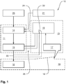
- the Fig. 1 11 shows a circuit diagram of an embodiment of a monitoring arrangement 10.
- the monitoring arrangement 10 comprises a control device 11 for controlling and supplying power to a heating device 12 and a safety device 13 for interrupting the power supply of the heating device 12.
- the control device 11 is formed by a heating control device 14 and a heating power section 15.
- the safety device 13 comprises an identification unit 17 arranged on a cabin 16 with the heater 12, which is arranged here in particular on a car door 18 of the car 16, as well as a safety device 19.
- a remote control device 20 is provided which can transmit signals to the control device 11 ,
- the control device 11 may be connected to a building control system 21.
- the safety device 19 may optionally have a safety relay 22, by means of which a connecting line 23 of the heater 12 to the control device 11 can be interrupted directly. Furthermore, the safety device 19 can be connected directly to the heating control unit 14 via a data bus 24 and send signals or commands via the data bus 24 to the heating control unit 14. In addition, the safety device is connected directly to the heating power section 15 via a safety temperature limiter circuit (STB) 25, so that a power relay (not shown here) of the heating power section 15 can be opened by the safety device 19.
- STB safety temperature limiter circuit
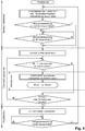
- FIG. 1 From a synopsis of Fig. 1 with the in Fig. 2
- the flowchart shown is an embodiment of the method for a Commissioning of the heater 12 forth.
- the power relay of the heating power part 15 is opened.
- a visual inspection of the heater 12 by a person in the cabin 16 done. If the person has determined that no objects or objects have been stored on the heater 12, the person triggers an enable signal on the identification unit 17 and closes the cabin door 18 within a defined period of time.
- the safety device 19 thus receives the release signal and the closing signal of the car door 18 and transmits a release command to the control device 11, wherein the safety device itself changes into a monitoring operation.
- the control device 11 can receive a switch-on signal from the remote control device 20, close the power relay and supply the heater 12 with power and thus heat it up.
- the safety device 19 changes to a control mode. If the car door 18 is opened before the changeover to regular operation, an opening signal is transmitted to the safety device 19, which then changes to an alarm mode and interrupts a power supply of the heater 12 by opening the power relay in the heating power section 15. Also, the safety temperature limiter circuit 25 is opened.
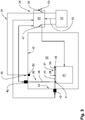
- monitoring assembly 30 has, in contrast to the in the Fig. 1 and Fig. 2 described monitoring arrangement further, additional functionalities.
- the monitoring arrangement 30 likewise serves to start up a heating device 31 within a cabin 32 and comprises a control device 33 and a safety device 34.
- the safety device 34 is formed from a safety device 35 and light barriers 36 and 37. With the light barriers 36 and 37, a tray of objects or objects on a surface 39 of the top 38 is monitored on an upper side 38 of the heater 31.
- the photocell 36 is vertically aligned and arranged on a ceiling 40 of the cabin 32.
- a reflector 41 of the light barrier 36 is arranged on the surface 39, such that a light beam 48 of the light barrier 36 is projected by a transmitter-receiver 42 of the light barrier 36 onto the reflector 41 and thrown back from this to the transmitter-receiver 42.
- the light barrier 37 or its transmitter-receiver 43 is attached to a wall 44 of the cabin 32, such that a light beam 45 extends horizontally to a reflector 46 on the heater 31. Placing an object, not shown here, on the surface 39 inevitably leads to an interruption of the light beam 45.
- the light barriers 36 and 37 are connected to the safety device 35.
- the heater 31 is connected via the safety device 35 to the control device 33, which supplies the heater 31 with power.
- a safety relay 47 is provided, with which a direct interruption of the power supply of the heater 31 occurs when one of the light barriers 36 and 37 detects an interruption of a light beam 45 and 48, respectively.
- the safety device 34 comprises a temperature limiting device 49 with a temperature sensor 50 inside the cabin 32, which is connected via a connection relay 51 in the safety device 35 to the control device 33.
- An opening of the connection relay 51 also leads to an interruption of the power supply of the heater 31 in the control device 33. The interruption or opening of the connection relay 51 always occurs even with an interruption of one of the light beams 45 and 48.
- control device 33 via a signal line 52nd connected to the safety device 35, so that when switching on the control device 33, the safety device 35 can also be turned on.
- the safety device 35 has a switching device 53 with which the safety device 34 can be reset to a standby or control mode.
Landscapes
- Health & Medical Sciences (AREA)
- Public Health (AREA)
- Epidemiology (AREA)
- Pain & Pain Management (AREA)
- Physical Education & Sports Medicine (AREA)
- Rehabilitation Therapy (AREA)
- Life Sciences & Earth Sciences (AREA)
- Animal Behavior & Ethology (AREA)
- General Health & Medical Sciences (AREA)
- Veterinary Medicine (AREA)
- Air-Conditioning For Vehicles (AREA)
Applications Claiming Priority (1)
| Application Number | Priority Date | Filing Date | Title |
|---|---|---|---|
| DE102018102030.9A DE102018102030A1 (de) | 2018-01-30 | 2018-01-30 | Verfahren und Überwachungsanordnung für eine Inbetriebsetzung von Heizgeräten |
Publications (1)
| Publication Number | Publication Date |
|---|---|
| EP3517092A1 true EP3517092A1 (fr) | 2019-07-31 |
Family
ID=65241118
Family Applications (1)
| Application Number | Title | Priority Date | Filing Date |
|---|---|---|---|
| EP19152708.4A Withdrawn EP3517092A1 (fr) | 2018-01-30 | 2019-01-21 | Procédé et dispositif de surveillance pour une mise en service des appareils de chauffage |
Country Status (3)
| Country | Link |
|---|---|
| EP (1) | EP3517092A1 (fr) |
| DE (1) | DE102018102030A1 (fr) |
| RU (1) | RU2019102151A (fr) |
Citations (7)
| Publication number | Priority date | Publication date | Assignee | Title |
|---|---|---|---|---|
| DE20104810U1 (de) * | 2000-03-21 | 2001-08-16 | Gitronica S.R.L., Montelupone | Erkennungssystem zum Aktivieren einer Vorrichtung |
| DE20115590U1 (de) * | 2001-09-21 | 2002-01-17 | Fasel GmbH, 79232 March | Saunaanlage |
| DE20315907U1 (de) * | 2003-10-13 | 2003-12-18 | Alre-It Regeltechnik Gmbh | Kontrollschaltung eines beheizbaren Raumes |
| DE202012003274U1 (de) * | 2012-03-29 | 2012-05-09 | Frank Finsterbusch | Sicherheitsschaltung einer Sauna mit Zeitvorwahl und Dreifach-Kontrolle zur Vermeidung von Saunabränden |
| WO2014001916A2 (fr) * | 2012-05-24 | 2014-01-03 | Si Barghelame | Sauna et séchoir multifonctions pliables |
| DE202014105977U1 (de) * | 2014-12-11 | 2015-02-26 | Schumacher & Partner Gesellschaft Mit Beschränkter Haftung | Behandlungskabine |
| US20170131693A1 (en) * | 2012-06-30 | 2017-05-11 | David Floyd Shurtleff | Exercise Sauna Having Far Infrared Heating Elements and Configurable Seating |
-
2018
- 2018-01-30 DE DE102018102030.9A patent/DE102018102030A1/de not_active Ceased
-
2019
- 2019-01-21 EP EP19152708.4A patent/EP3517092A1/fr not_active Withdrawn
- 2019-01-25 RU RU2019102151A patent/RU2019102151A/ru unknown
Patent Citations (7)
| Publication number | Priority date | Publication date | Assignee | Title |
|---|---|---|---|---|
| DE20104810U1 (de) * | 2000-03-21 | 2001-08-16 | Gitronica S.R.L., Montelupone | Erkennungssystem zum Aktivieren einer Vorrichtung |
| DE20115590U1 (de) * | 2001-09-21 | 2002-01-17 | Fasel GmbH, 79232 March | Saunaanlage |
| DE20315907U1 (de) * | 2003-10-13 | 2003-12-18 | Alre-It Regeltechnik Gmbh | Kontrollschaltung eines beheizbaren Raumes |
| DE202012003274U1 (de) * | 2012-03-29 | 2012-05-09 | Frank Finsterbusch | Sicherheitsschaltung einer Sauna mit Zeitvorwahl und Dreifach-Kontrolle zur Vermeidung von Saunabränden |
| WO2014001916A2 (fr) * | 2012-05-24 | 2014-01-03 | Si Barghelame | Sauna et séchoir multifonctions pliables |
| US20170131693A1 (en) * | 2012-06-30 | 2017-05-11 | David Floyd Shurtleff | Exercise Sauna Having Far Infrared Heating Elements and Configurable Seating |
| DE202014105977U1 (de) * | 2014-12-11 | 2015-02-26 | Schumacher & Partner Gesellschaft Mit Beschränkter Haftung | Behandlungskabine |
Also Published As
| Publication number | Publication date |
|---|---|
| DE102018102030A1 (de) | 2019-08-01 |
| RU2019102151A (ru) | 2020-07-27 |
Similar Documents
| Publication | Publication Date | Title |
|---|---|---|
| EP2819136B1 (fr) | Bouton d'urgence doté d'un affichage déplaçable | |
| DE69007583T2 (de) | Apparat und Verfahren zur Kontrolle eines Stromregelventils in Abhängigkeit von der Annäherung eines menschlichen Körperteils. | |
| DE69406019T2 (de) | Sicherheitsleistungsunterbrechung | |
| DE69833121T2 (de) | Zugangskontrolle für computersystem | |
| US6965294B1 (en) | Workspace security system | |
| US7847675B1 (en) | Security system | |
| DE102016206912B4 (de) | Verfahren zur Steuerung eines Kochgerätes und Kochgerät | |
| DE10256464B4 (de) | Verfahren zur Steuerung eines elektrischen Geräts sowie Gerätesteuerung für elektrische Geräte | |
| DE112016004525T5 (de) | Elektronische Tastatursperre und elektronische Verriegelungssystem für Möbel, Schränke oder Schliessfächer | |
| AT10547U1 (de) | Aufbewahrungsautomat für gegenstände | |
| HK1212478A1 (en) | Method, device and system for controlling indoor power supply | |
| DE4138078A1 (de) | Tuersicherheitssystem | |
| CN104050743A (zh) | 一种门禁系统的设防监控系统及方法 | |
| EP2568100B2 (fr) | Système pour une porte | |
| DE102014207737A1 (de) | Verfahren zum Betreiben eines Haushaltsgeräts mit spezifischer Nutzeridentifikation sowie Haushaltsgerät und System mit einem Haushaltsgerät | |
| DE102019209073A1 (de) | Haushaltsgerät mit Näherungsdetektor | |
| EP3699347A1 (fr) | Appareil électroménager | |
| EP3839353A1 (fr) | Procédé de fonctionnement d'un appareil de cuisson et appareil de cuisson | |
| EP4138104B1 (fr) | Système de sécurité | |
| DE102013110385A1 (de) | Distributionsautomat für die Verteilung, Übergabe, temporäre Aufbewahrung oder den automatisierten Verkauf von Gegenständen | |
| EP3517092A1 (fr) | Procédé et dispositif de surveillance pour une mise en service des appareils de chauffage | |
| DE19802558A1 (de) | Steuerung für ein Elektrowärmegerät | |
| DE19629155C2 (de) | Verfahren und Vorrichtung zur Sicherheitsabschaltung elektrischer Kochgeräte | |
| DE202018006673U1 (de) | Überwachungsanordnung für eine Inbetriebsetzung von Heizgeräten | |
| EP3517093A1 (fr) | Procédé et dispositif de surveillance pour une mise en service des appareils de chauffage |
Legal Events
| Date | Code | Title | Description |
|---|---|---|---|
| PUAI | Public reference made under article 153(3) epc to a published international application that has entered the european phase |
Free format text: ORIGINAL CODE: 0009012 |
|
| STAA | Information on the status of an ep patent application or granted ep patent |
Free format text: STATUS: THE APPLICATION HAS BEEN PUBLISHED |
|
| AK | Designated contracting states |
Kind code of ref document: A1 Designated state(s): AL AT BE BG CH CY CZ DE DK EE ES FI FR GB GR HR HU IE IS IT LI LT LU LV MC MK MT NL NO PL PT RO RS SE SI SK SM TR |
|
| AX | Request for extension of the european patent |
Extension state: BA ME |
|
| STAA | Information on the status of an ep patent application or granted ep patent |
Free format text: STATUS: REQUEST FOR EXAMINATION WAS MADE |
|
| 17P | Request for examination filed |
Effective date: 20190912 |
|
| RBV | Designated contracting states (corrected) |
Designated state(s): AL AT BE BG CH CY CZ DE DK EE ES FI FR GB GR HR HU IE IS IT LI LT LU LV MC MK MT NL NO PL PT RO RS SE SI SK SM TR |
|
| STAA | Information on the status of an ep patent application or granted ep patent |
Free format text: STATUS: EXAMINATION IS IN PROGRESS |
|
| 17Q | First examination report despatched |
Effective date: 20200414 |
|
| STAA | Information on the status of an ep patent application or granted ep patent |
Free format text: STATUS: THE APPLICATION HAS BEEN WITHDRAWN |
|
| 18W | Application withdrawn |
Effective date: 20201015 |