EP3524145B1 - Système de mesure - Google Patents
Système de mesure Download PDFInfo
- Publication number
- EP3524145B1 EP3524145B1 EP19163712.3A EP19163712A EP3524145B1 EP 3524145 B1 EP3524145 B1 EP 3524145B1 EP 19163712 A EP19163712 A EP 19163712A EP 3524145 B1 EP3524145 B1 EP 3524145B1
- Authority
- EP
- European Patent Office
- Prior art keywords
- sensor
- signal
- measurement system
- parameter
- measure
- Prior art date
- Legal status (The legal status is an assumption and is not a legal conclusion. Google has not performed a legal analysis and makes no representation as to the accuracy of the status listed.)
- Active
Links
Images



Classifications
-
- A—HUMAN NECESSITIES
- A61—MEDICAL OR VETERINARY SCIENCE; HYGIENE
- A61B—DIAGNOSIS; SURGERY; IDENTIFICATION
- A61B5/00—Measuring for diagnostic purposes; Identification of persons
- A61B5/68—Arrangements of detecting, measuring or recording means, e.g. sensors, in relation to patient
- A61B5/6846—Arrangements of detecting, measuring or recording means, e.g. sensors, in relation to patient specially adapted to be brought in contact with an internal body part, i.e. invasive
- A61B5/6847—Arrangements of detecting, measuring or recording means, e.g. sensors, in relation to patient specially adapted to be brought in contact with an internal body part, i.e. invasive mounted on an invasive device
- A61B5/6851—Guide wires
-
- A—HUMAN NECESSITIES
- A61—MEDICAL OR VETERINARY SCIENCE; HYGIENE
- A61B—DIAGNOSIS; SURGERY; IDENTIFICATION
- A61B5/00—Measuring for diagnostic purposes; Identification of persons
- A61B5/02—Detecting, measuring or recording for evaluating the cardiovascular system, e.g. pulse, heart rate, blood pressure or blood flow
- A61B5/026—Measuring blood flow
-
- A—HUMAN NECESSITIES
- A61—MEDICAL OR VETERINARY SCIENCE; HYGIENE
- A61B—DIAGNOSIS; SURGERY; IDENTIFICATION
- A61B5/00—Measuring for diagnostic purposes; Identification of persons
- A61B5/68—Arrangements of detecting, measuring or recording means, e.g. sensors, in relation to patient
- A61B5/6846—Arrangements of detecting, measuring or recording means, e.g. sensors, in relation to patient specially adapted to be brought in contact with an internal body part, i.e. invasive
- A61B5/6847—Arrangements of detecting, measuring or recording means, e.g. sensors, in relation to patient specially adapted to be brought in contact with an internal body part, i.e. invasive mounted on an invasive device
- A61B5/6852—Catheters
-
- A—HUMAN NECESSITIES
- A61—MEDICAL OR VETERINARY SCIENCE; HYGIENE
- A61B—DIAGNOSIS; SURGERY; IDENTIFICATION
- A61B5/00—Measuring for diagnostic purposes; Identification of persons
-
- A—HUMAN NECESSITIES
- A61—MEDICAL OR VETERINARY SCIENCE; HYGIENE
- A61B—DIAGNOSIS; SURGERY; IDENTIFICATION
- A61B5/00—Measuring for diagnostic purposes; Identification of persons
- A61B5/0002—Remote monitoring of patients using telemetry, e.g. transmission of vital signals via a communication network
- A61B5/0031—Implanted circuitry
-
- A—HUMAN NECESSITIES
- A61—MEDICAL OR VETERINARY SCIENCE; HYGIENE
- A61B—DIAGNOSIS; SURGERY; IDENTIFICATION
- A61B5/00—Measuring for diagnostic purposes; Identification of persons
- A61B5/0059—Measuring for diagnostic purposes; Identification of persons using light, e.g. diagnosis by transillumination, diascopy, fluorescence
- A61B5/0082—Measuring for diagnostic purposes; Identification of persons using light, e.g. diagnosis by transillumination, diascopy, fluorescence adapted for particular medical purposes
- A61B5/0084—Measuring for diagnostic purposes; Identification of persons using light, e.g. diagnosis by transillumination, diascopy, fluorescence adapted for particular medical purposes for introduction into the body, e.g. by catheters
-
- A—HUMAN NECESSITIES
- A61—MEDICAL OR VETERINARY SCIENCE; HYGIENE
- A61B—DIAGNOSIS; SURGERY; IDENTIFICATION
- A61B5/00—Measuring for diagnostic purposes; Identification of persons
- A61B5/02—Detecting, measuring or recording for evaluating the cardiovascular system, e.g. pulse, heart rate, blood pressure or blood flow
-
- A—HUMAN NECESSITIES
- A61—MEDICAL OR VETERINARY SCIENCE; HYGIENE
- A61B—DIAGNOSIS; SURGERY; IDENTIFICATION
- A61B5/00—Measuring for diagnostic purposes; Identification of persons
- A61B5/02—Detecting, measuring or recording for evaluating the cardiovascular system, e.g. pulse, heart rate, blood pressure or blood flow
- A61B5/0205—Simultaneously evaluating both cardiovascular conditions and different types of body conditions, e.g. heart and respiratory condition
- A61B5/02055—Simultaneously evaluating both cardiovascular condition and temperature
-
- A—HUMAN NECESSITIES
- A61—MEDICAL OR VETERINARY SCIENCE; HYGIENE
- A61B—DIAGNOSIS; SURGERY; IDENTIFICATION
- A61B5/00—Measuring for diagnostic purposes; Identification of persons
- A61B5/02—Detecting, measuring or recording for evaluating the cardiovascular system, e.g. pulse, heart rate, blood pressure or blood flow
- A61B5/021—Measuring pressure in heart or blood vessels
- A61B5/0215—Measuring pressure in heart or blood vessels by means inserted into the body
-
- A—HUMAN NECESSITIES
- A61—MEDICAL OR VETERINARY SCIENCE; HYGIENE
- A61B—DIAGNOSIS; SURGERY; IDENTIFICATION
- A61B5/00—Measuring for diagnostic purposes; Identification of persons
- A61B5/02—Detecting, measuring or recording for evaluating the cardiovascular system, e.g. pulse, heart rate, blood pressure or blood flow
- A61B5/021—Measuring pressure in heart or blood vessels
- A61B5/0215—Measuring pressure in heart or blood vessels by means inserted into the body
- A61B5/02156—Calibration means
-
- A—HUMAN NECESSITIES
- A61—MEDICAL OR VETERINARY SCIENCE; HYGIENE
- A61B—DIAGNOSIS; SURGERY; IDENTIFICATION
- A61B5/00—Measuring for diagnostic purposes; Identification of persons
- A61B5/06—Devices, other than using radiation, for detecting or locating foreign bodies ; Determining position of diagnostic devices within or on the body of the patient
-
- A—HUMAN NECESSITIES
- A61—MEDICAL OR VETERINARY SCIENCE; HYGIENE
- A61B—DIAGNOSIS; SURGERY; IDENTIFICATION
- A61B5/00—Measuring for diagnostic purposes; Identification of persons
- A61B5/06—Devices, other than using radiation, for detecting or locating foreign bodies ; Determining position of diagnostic devices within or on the body of the patient
- A61B5/061—Determining position of a probe within the body employing means separate from the probe, e.g. sensing internal probe position employing impedance electrodes on the surface of the body
- A61B5/062—Determining position of a probe within the body employing means separate from the probe, e.g. sensing internal probe position employing impedance electrodes on the surface of the body using magnetic field
-
- A—HUMAN NECESSITIES
- A61—MEDICAL OR VETERINARY SCIENCE; HYGIENE
- A61B—DIAGNOSIS; SURGERY; IDENTIFICATION
- A61B5/00—Measuring for diagnostic purposes; Identification of persons
- A61B5/06—Devices, other than using radiation, for detecting or locating foreign bodies ; Determining position of diagnostic devices within or on the body of the patient
- A61B5/065—Determining position of the probe employing exclusively positioning means located on or in the probe, e.g. using position sensors arranged on the probe
-
- A—HUMAN NECESSITIES
- A61—MEDICAL OR VETERINARY SCIENCE; HYGIENE
- A61B—DIAGNOSIS; SURGERY; IDENTIFICATION
- A61B5/00—Measuring for diagnostic purposes; Identification of persons
- A61B5/145—Measuring characteristics of blood in vivo, e.g. gas concentration or pH-value ; Measuring characteristics of body fluids or tissues, e.g. interstitial fluid or cerebral tissue
- A61B5/14503—Measuring characteristics of blood in vivo, e.g. gas concentration or pH-value ; Measuring characteristics of body fluids or tissues, e.g. interstitial fluid or cerebral tissue invasive, e.g. introduced into the body by a catheter or needle or using implanted sensors
-
- A—HUMAN NECESSITIES
- A61—MEDICAL OR VETERINARY SCIENCE; HYGIENE
- A61B—DIAGNOSIS; SURGERY; IDENTIFICATION
- A61B5/00—Measuring for diagnostic purposes; Identification of persons
- A61B5/145—Measuring characteristics of blood in vivo, e.g. gas concentration or pH-value ; Measuring characteristics of body fluids or tissues, e.g. interstitial fluid or cerebral tissue
- A61B5/1495—Calibrating or testing of in-vivo probes
-
- A—HUMAN NECESSITIES
- A61—MEDICAL OR VETERINARY SCIENCE; HYGIENE
- A61B—DIAGNOSIS; SURGERY; IDENTIFICATION
- A61B6/00—Apparatus or devices for radiation diagnosis; Apparatus or devices for radiation diagnosis combined with radiation therapy equipment
-
- A—HUMAN NECESSITIES
- A61—MEDICAL OR VETERINARY SCIENCE; HYGIENE
- A61B—DIAGNOSIS; SURGERY; IDENTIFICATION
- A61B6/00—Apparatus or devices for radiation diagnosis; Apparatus or devices for radiation diagnosis combined with radiation therapy equipment
- A61B6/12—Arrangements for detecting or locating foreign bodies
-
- G—PHYSICS
- G08—SIGNALLING
- G08C—TRANSMISSION SYSTEMS FOR MEASURED VALUES, CONTROL OR SIMILAR SIGNALS
- G08C17/00—Arrangements for transmitting signals characterised by the use of a wireless electrical link
- G08C17/02—Arrangements for transmitting signals characterised by the use of a wireless electrical link using a radio link
-
- G—PHYSICS
- G08—SIGNALLING
- G08C—TRANSMISSION SYSTEMS FOR MEASURED VALUES, CONTROL OR SIMILAR SIGNALS
- G08C19/00—Electric signal transmission systems
- G08C19/16—Electric signal transmission systems in which transmission is by pulses
-
- H—ELECTRICITY
- H04—ELECTRIC COMMUNICATION TECHNIQUE
- H04B—TRANSMISSION
- H04B1/00—Details of transmission systems, not covered by a single one of groups H04B3/00 - H04B13/00; Details of transmission systems not characterised by the medium used for transmission
- H04B1/69—Spread spectrum techniques
- H04B1/713—Spread spectrum techniques using frequency hopping
-
- A—HUMAN NECESSITIES
- A61—MEDICAL OR VETERINARY SCIENCE; HYGIENE
- A61B—DIAGNOSIS; SURGERY; IDENTIFICATION
- A61B2562/00—Details of sensors; Constructional details of sensor housings or probes; Accessories for sensors
- A61B2562/08—Sensors provided with means for identification, e.g. barcodes or memory chips
- A61B2562/085—Sensors provided with means for identification, e.g. barcodes or memory chips combined with means for recording calibration data
Definitions
- the present invention relates to a transceiver unit and a communication unit for a pressure measurement system for measuring a physiological variable in a body.
- Blood pressure transducers could be used interchangeably with patient monitors from different manufacturers. As such, medical personnel were not required to select a specific transducer for use with a specific monitor. Further, hospital investments in pre-existing patient monitors were preserved, thereby reducing costs. As a consequence, vital signs monitors adhering to these proportionality standards have achieved almost universal acceptance in medical environments.
- the blood pressure transducers and monitors that have been previously used, and the resulting standards that have evolved, are not without drawbacks.
- the sensors used in these systems were typically positioned external to the patient's body and placed in fluid communication with the body cavity via a fluid-filled catheter line. Pressure variations within the body cavity are then indirectly communicated to the diaphragm by way of fluid contained with the catheter line. As such, the accuracy of such systems has suffered due to variations in hydrostatic pressure and other inconsistencies associated with the fluid column.
- a solution to the insulation problem is to use wireless communication to transmit the measure values from the sensor to the monitoring device.
- control unit may be attached to the core wire of the guide wire via a connection wire using a suitable connector means, such as a crocodile clip-type connector, or if the connection wire is omitted, directly connecting the core wire to the control unit by a suitable connector.
- a suitable connector means such as a crocodile clip-type connector
- the connector is not further discussed in the above application.
- Other types of sensors mounted on elongated members for insertion into the body are also known.
- catheter-mounted sensors for detecting a magnetic field which are used to determine the location and orientation of an invasive medical instrument.
- one or more cables or leads for transmitting the signals are connected to the sensor, and are routed along the guide wire to be passed out from the vessel to the external physiology monitor, conventionally via physical cables.
- the guide wire is typically provided with a central metal wire (core wire) serving as a support for the sensor and (optionally) also as an electrical connection to the sensor, and a surrounding tubing.
- a guide wire typically comprises a core wire, leads and a protective tubing.
- Figure 2 is a schematic overview illustrating the application of the present disclosure.
- the pressure measurement system comprises a pressure sensor wire with a pressure sensor to measure pressure inside a patient, and to provide measured pressure data to an external device.
- the pressure sensor wire is adapted to be connected, at its proximal end, to a transceiver unit adapted to wirelessly communicate via a radio frequency signal with a communication unit arranged in connection with an external device (also referred to as external physiology monitor), in order to transfer measured pressure data to the external device.
- FIG. 3 shows a block diagram schematically illustrating the transceiver unit.
- the transceiver unit is adapted to be connected to the proximal end of a pressure sensor wire provided, at its distal end, with a pressure sensor to measure pressure inside a patient.
- the transceiver unit comprises a sensor signal adapting circuitry 2, which will be described in greater detail below, a communication module 4, connected to the adapting circuitry 2, that will handled the wireless communication with the communication unit.
- the radio frequency signal transmits the data as data packets, i.e. in a digital form.
- the radio frequency transmission may, as an alternative, be an analogue data transmission.
- the communication signal may be an electromagnetic wave signal, e.g. a radio frequency signal, an infrared signal, or a light signal.
- the communication signal is a radio frequency signal
- the transceiver unit and the communication unit are described in connection with the preferred embodiment it should be appreciated that relevant features would be equally applicable in case any of the alternative communication signals is used.
- the communication module is connected to an antenna 6.
- the antenna is illustrated as protruding outside the transceiver unit but may, as in an alternative, be integrated into the housing of the transceiver unit.
- the pressure sensor wire is adapted to be inserted into an elongated aperture 8 of the transceiver unit.
- the aperture is at its inner surface provided with a number of electrical connecting surfaces (not shown) to be connected to electrode surfaces at the proximal end of the pressure sensor wire when inserted into the aperture 8.
- the transceiver unit is further provided with wire fastening means (not shown) to firmly fixate the wire when correctly inserted into the aperture.
- the transceiver unit is preferably activated and initiated via an activation button 12 arranged at the housing of the unit.
- the activation button is preferably mechanically activated.
- the transceiver unit is activated and initiated when the proximal end to the sensor wire is correctly inserted into the unit. This may e.g. be achieved by arranging a push button at the bottom of the cavity into which the pressure wire is inserted.
- the transceiver unit comprises energy means to energize the transceiver unit and the circuitry of the connected pressure sensor wire.
- the energy means is preferably a battery or a capacitor that e.g. may be included in the sensor signal adapting circuitry.
- the pressure sensor wire as well as the transceiver unit are preferably disposable units that must be able to sterilise prior use.
- an attachment means is provided at the housing of the unit.
- the attachment means may be in the form of a strap, a clip or a hook, i.e. any mechanical attachment means enabling the transceiver unit to be stationary during use.
- the programmable sensor conditioning means is preferably a PGA309 programmable analog sensor conditioner (available from Texas Instruments Inc.) specifically designed for bridge sensors.
- the communication between the transceiver unit and the communication unit is preferably performed in a so-called license-free radio frequency interval.
- license-free radio refers to the permission granted by government agencies to allow multiple radios to operate in a specified frequency band at one time. These license-free bands are known as the ISM (Industrial, Scientific and Medical) bands.
- the two most commonly used ISM bands are referred to as the 900 MHz and the 2.4 GHz bands. Both permit the use of license-free Spread Spectrum radios within them.
- the 900 MHz band is used in the Americas.
- the 2.4 GHz band is used (with differing power constraints) throughout most of the world. While there are some differences between the characteristics of the two bands, the 900 MHz band typically allows for higher power and longer distance transmissions while the 2.4 GHz band, with its wider bandwidth, allows for higher data rates.
- the 869 MHz and 433 MHz bands are also classified as ISM bands and China has opened the 220 MHz band to license-free radios.
- a frequency band of 2.4 GHz (2.2 - 2.6 GHz) is used.
- a typical communication distance would be less than 10 meters.
- the transceiver unit comprises a first communication module to handle the radio frequency communication with the communication unit that is provided with a second communication module.
- the transceiver unit By pressing the activation button on the transceiver unit it is activated and will then try to establish a radio link connection with the communication unit. This is preferably performed by a conventional handshake procedure in order to identify the transceiver unit. The system is now ready to receive measured sensor data.
- Pressure sensor values measured at specific times are respectively designated P1, P2, P3, P4, P5, etc, are applied to the communication module of the transceiver unit. These values are preferably transmitted in packets of three values per packet, e.g. P1, P2 and P3, forming packet P1P2P3; the next packet comprises values P2, P3 and P4 forming packet P2P3P4, and the next packet comprises values P3, P4 and P5 forming packet P3P4P5, etc. Consecutive packets are transmitted at different frequencies, i.e.
- the conditioner means generates an analog output voltage signal related to the sensor signal such that the measured physiological variable, i.e. the pressure, may be retrieved by the external device.
- the output voltage (V IN1 - V IN2 ) of the bridge is a voltage proportional to the pressure applied to the sensor.
- the sensor output voltage (V IN1 - V IN2 ) (sensor signal in Fig. 4 ) of the bridge is proportional to the pressure applied to the sensor, which for a given pressure will vary with the applied excitation voltage.
- This sensor output voltage is preferably compensated for temperature variation at the site of the sensor and is applied to the PGA309 circuit.
- the PGA309 circuit also includes gain blocks for adjusting the output signal from that circuit and used in addition to the output amplifying means mentioned above.
- a processing means preferably a microprocessor (e.g. a PIC16C770 or a nRF24E1, shown with dashed lines in Fig. 4 ) may further be employed to process and adapt the analog output voltage V OUT of the conditioned sensor, which output voltage is supplied via the PGA309 programmable analog sensor conditioner.
- the analog output signal from the PGA309 circuit is A/D-converted prior it is applied to the processing means.
- DAC multiplying digital-analog converter
- the resulting product is wirelessly sent (after having been filtered) to the external device and is proportional to the measured sensor signal and the reference voltage.
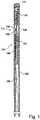
- a pressure sensor wire comprising a pressure sensor element for measuring pressure inside the patient and generating a pressure sensor signal in pressure.
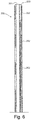
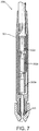
- the sensor wire of Fig. 1 may include a sensor element configured to measure any physiological parameter, such as pressure inside the patient, temperature inside the patient, and blood flow inside the patient.
- one suitable sensor may be a temperature sensor for measuring temperature by observing the resistance of a conductor having temperature sensitive resistance as described in U.S. Patent No. 6,615,067 , which is incorporate herein by reference in its entirety.
- Another suitable sensor may be a sensor for measuring blood flow as described in U.S. Patent No.
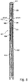
- the two sensor elements of Fig. 8 may measure two different physiological parameters or measure two different non-physiological parameters.
- any number of sensor elements may be used such as one, two, three, four, five, or more sensor elements in which the sensor elements may measure blood pressure; blood temperature; blood flow; one or more blood analyte concentrations; a magnetic field; a magnetic flux; an X-ray field; an electromagnetic field; an optical signal; the presence of a metallic instrument, implantable device, or a foreign object (such as, for example, a stent, needle, implantable drug delivery device, pacemaker, etc.), and/or any combination thereof.
- the sensor signal adapting circuitry 2 is configured to filter, process, and format signal(s) received from the sensor wire.
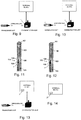
- the sensor signal adapting circuitry 2 may be fully located within the housing of the transceiver unit (see Fig. 3 ) or fully located within the communication unit (see Fig. 9 ).
- the sensor signal adapting circuitry 2 may be partially located within the housing (a part of the circuitry is identified as 2' in Fig. 10 ) and be partially located within the communication unit (another part of the circuitry is identified as 2" in Fig. 10 ).
- the sensor signal adapting circuitry 2 may be fully located near the sensor(s) at the distal end of the sensor wire (see Fig. 11 ).
- the sensor signal adapting circuitry is partially located near the sensor(s) at the distal end of the sensor wire (a part of the circuitry is identified as 2'" in Fig. 12 ) with the other portions of the sensor signal adapting circuitry being partially located within the housing and/or located within the communication unit.
- the sensor signal adapting circuitry 2 may be fully located at the external device (see Fig. 13 ).
- the sensor signal adapting circuitry may be partially located at the external device (a part of the circuitry is identified as 2"" in Fig.
Landscapes
- Health & Medical Sciences (AREA)
- Life Sciences & Earth Sciences (AREA)
- Engineering & Computer Science (AREA)
- Physics & Mathematics (AREA)
- Medical Informatics (AREA)
- Surgery (AREA)
- General Health & Medical Sciences (AREA)
- Heart & Thoracic Surgery (AREA)
- Biomedical Technology (AREA)
- Molecular Biology (AREA)
- Animal Behavior & Ethology (AREA)
- Public Health (AREA)
- Veterinary Medicine (AREA)
- Pathology (AREA)
- Biophysics (AREA)
- Cardiology (AREA)
- Physiology (AREA)
- Computer Networks & Wireless Communication (AREA)
- Optics & Photonics (AREA)
- General Physics & Mathematics (AREA)
- Human Computer Interaction (AREA)
- Vascular Medicine (AREA)
- Nuclear Medicine, Radiotherapy & Molecular Imaging (AREA)
- Radiology & Medical Imaging (AREA)
- High Energy & Nuclear Physics (AREA)
- Signal Processing (AREA)
- Hematology (AREA)
- Pulmonology (AREA)
- Measuring Pulse, Heart Rate, Blood Pressure Or Blood Flow (AREA)
- Measuring And Recording Apparatus For Diagnosis (AREA)
- Robotics (AREA)
- Measurement Of The Respiration, Hearing Ability, Form, And Blood Characteristics Of Living Organisms (AREA)
Claims (10)
- Système de mesure comprenant :un fil de guidage de capteur (401) comprenant :une partie insérable au niveau de extrémité distale du fil de guidage de capteur, la partie insérable étant configurée pour être insérée dans un vaisseau sanguin du corps d'un patient, etun premier capteur (408A) disposé dans la partie insérable du fil de guidage de capteur (401), le premier capteur (408A) étant configuré pour mesurer un premier paramètre lorsqu'il est inséré dans le vaisseau sanguin du corps du patient ;un premier circuit d'adaptation de signal de capteur (2) configuré pour filtrer, traiter et formater des signaux reçus du premier capteur (408A) concernant ledit premier paramètre, afin de produire un premier signal filtré, traité et formaté contenant des données concernant ledit premier paramètre ; etune unité émetteur-récepteur comprenant un boîtier adapté pour être raccordé à une extrémité proximale du fil de guidage de capteur (401), le boîtier étant configuré pour rester à l'extérieur du corps du patient,le système de mesure comprend en outre au moins l'un parmi (i) un dispositif extérieur dédié à la surveillance d'un patient comprenant un moniteur, un logiciel et des connexions pour recevoir et traiter des données associées aux premier et deuxième paramètres ou (ii) un moniteur de laboratoire de cathétérisme standard,caractérisé en ce que :le fil de guidage de capteur (401) comprend un deuxième capteur (408B) disposé dans la partie insérable du fil de guidage de capteur (401), le deuxième capteur (408B) étant configuré pour mesurer un deuxième paramètre lorsqu'il est inséré dans le vaisseau sanguin du corps du patient, et le deuxième paramètre étant différent du premier paramètre,le système de mesure comprend en outre un deuxième circuit d'adaptation de signal de capteur (2) configuré pour filtrer, traiter et formater des signaux reçus du deuxième capteur concernant ledit deuxième paramètre, afin de produire un deuxième signal filtré, traité et formaté contenant des données concernant ledit deuxième paramètre,l'unité émetteur-récepteur comprend en outre au moins un premier module de communication (4) configuré pour transmettre, via un signal de communication sans fil, des données concernant lesdits premier et deuxième paramètres à au moins un deuxième module de communication logé dans (i) ledit dispositif extérieur dédié à la surveillance d'un patient comprenant le moniteur, le logiciel et les connexions pour recevoir et traiter des données associées aux premier et deuxième paramètres ou (ii) ledit moniteur de laboratoire de cathétérisme standard, etau moins l'un desdits circuits d'adaptation de signal de capteur (2) est partiellement situé dans le boîtier de l'unité d'émetteur-récepteur et est partiellement situé dans (i) ledit dispositif extérieur dédié à la surveillance d'un patient comprenant le moniteur, le logiciel et les connexions pour recevoir et traiter des données associées aux premier et deuxième paramètres ou (ii) ledit moniteur de laboratoire de cathétérisme standard.
- Système de mesure selon la revendication 1, dans lequel :le premier capteur (408A) est configuré pour mesurer un premier paramètre physiologique,le deuxième capteur (408B) est configuré pour mesurer un deuxième paramètre physiologique, etles données transférées à partir du premier module de communication (4) constituent des données relatives aux premier et deuxième paramètres physiologiques.
- Système de mesure selon la revendication 2, dans lequel chacun du premier capteur (408A) et du deuxième capteur (408B) est configuré pour mesurer la pression sanguine, la température sanguine, le flux sanguin ou une ou plusieurs concentrations d'analyte sanguin.
- Système de mesure selon la revendication 1, dans lequel :le premier capteur (408A) est configuré pour mesurer un paramètre physiologique,le deuxième capteur (408B) est configuré pour mesurer un paramètre non physiologique, etles données transférées à partir du premier module de communication (4) constituent des données relatives aux paramètres physiologiques et non physiologiques.
- Système de mesure selon la revendication 4, dans lequel :le premier capteur (408A) est configuré pour mesurer la pression sanguine, la température sanguine, le flux sanguin ou une ou plusieurs concentrations d'analyte sanguin, etle deuxième capteur (408B) est configuré pour mesurer un champ magnétique, un flux magnétique, un champ de rayons X, un champ électromagnétique, un signal optique, ou la présence d'un instrument métallique, d'un dispositif implantable ou d'un objet étranger.
- Système de mesure selon l'une quelconque des revendications 1 à 5, dans lequel au moins l'un des circuits d'adaptation de signal de capteur comprend un conditionneur de capteur programmable, un étalonneur, un dispositif d'énergie et un amplificateur de sortie.
- Système de mesure selon l'une quelconque des revendications 1 à 6, dans lequel le premier capteur (408A) et le deuxième capteur (408B) sont montés dans une gaine ou un manchon de la partie insérable à l'extrémité distale du fil de guidage de capteur (401).
- Système de mesure selon l'une quelconque des revendications 1 à 7, dans lequel l'au moins un premier module de communication (4) comprend un premier module de communication unique (4) dans le boîtier, le premier module de communication unique (4) étant configuré pour transférer, via ledit signal de communication sans fil, lesdites données concernant lesdits premier et deuxième paramètres physiologiques à l'au moins un deuxième module de communication.
- Système de mesure selon l'une quelconque des revendications 1 à 8, dans lequel le deuxième capteur (408B) est configuré pour mesurer un signal optique.
- Système de mesure selon l'une quelconque des revendications 1 à 9, dans lequel le boîtier est adapté pour être raccordé directement à l'extrémité proximale du fil de guidage de capteur (401).
Priority Applications (1)
| Application Number | Priority Date | Filing Date | Title |
|---|---|---|---|
| EP20182598.1A EP3738639A1 (fr) | 2010-04-30 | 2011-04-28 | Système de mesure |
Applications Claiming Priority (4)
| Application Number | Priority Date | Filing Date | Title |
|---|---|---|---|
| US12/771,167 US8174395B2 (en) | 2006-11-20 | 2010-04-30 | Transceiver unit in a measurement system |
| EP16166321.6A EP3075309B1 (fr) | 2010-04-30 | 2011-04-28 | Système de mesure |
| PCT/EP2011/056704 WO2011135014A2 (fr) | 2010-04-30 | 2011-04-28 | Système de mesure |
| EP11718334A EP2563209A2 (fr) | 2010-04-30 | 2011-04-28 | Système de mesure |
Related Parent Applications (3)
| Application Number | Title | Priority Date | Filing Date |
|---|---|---|---|
| EP16166321.6A Division EP3075309B1 (fr) | 2010-04-30 | 2011-04-28 | Système de mesure |
| EP16166321.6A Division-Into EP3075309B1 (fr) | 2010-04-30 | 2011-04-28 | Système de mesure |
| EP11718334A Division EP2563209A2 (fr) | 2010-04-30 | 2011-04-28 | Système de mesure |
Related Child Applications (2)
| Application Number | Title | Priority Date | Filing Date |
|---|---|---|---|
| EP20182598.1A Division-Into EP3738639A1 (fr) | 2010-04-30 | 2011-04-28 | Système de mesure |
| EP20182598.1A Division EP3738639A1 (fr) | 2010-04-30 | 2011-04-28 | Système de mesure |
Publications (2)
| Publication Number | Publication Date |
|---|---|
| EP3524145A1 EP3524145A1 (fr) | 2019-08-14 |
| EP3524145B1 true EP3524145B1 (fr) | 2020-08-05 |
Family
ID=44316640
Family Applications (4)
| Application Number | Title | Priority Date | Filing Date |
|---|---|---|---|
| EP20182598.1A Withdrawn EP3738639A1 (fr) | 2010-04-30 | 2011-04-28 | Système de mesure |
| EP19163712.3A Active EP3524145B1 (fr) | 2010-04-30 | 2011-04-28 | Système de mesure |
| EP11718334A Ceased EP2563209A2 (fr) | 2010-04-30 | 2011-04-28 | Système de mesure |
| EP16166321.6A Active EP3075309B1 (fr) | 2010-04-30 | 2011-04-28 | Système de mesure |
Family Applications Before (1)
| Application Number | Title | Priority Date | Filing Date |
|---|---|---|---|
| EP20182598.1A Withdrawn EP3738639A1 (fr) | 2010-04-30 | 2011-04-28 | Système de mesure |
Family Applications After (2)
| Application Number | Title | Priority Date | Filing Date |
|---|---|---|---|
| EP11718334A Ceased EP2563209A2 (fr) | 2010-04-30 | 2011-04-28 | Système de mesure |
| EP16166321.6A Active EP3075309B1 (fr) | 2010-04-30 | 2011-04-28 | Système de mesure |
Country Status (8)
| Country | Link |
|---|---|
| US (8) | US8174395B2 (fr) |
| EP (4) | EP3738639A1 (fr) |
| JP (3) | JP2013526918A (fr) |
| CN (2) | CN106994008B (fr) |
| AU (1) | AU2011247600B2 (fr) |
| CA (2) | CA2966597C (fr) |
| CR (1) | CR20120567A (fr) |
| WO (1) | WO2011135014A2 (fr) |
Families Citing this family (94)
| Publication number | Priority date | Publication date | Assignee | Title |
|---|---|---|---|---|
| US8174395B2 (en) | 2006-11-20 | 2012-05-08 | St. Jude Medical Systems Ab | Transceiver unit in a measurement system |
| US11234650B2 (en) | 2006-11-20 | 2022-02-01 | St. Jude Medical Coordination Center Bvba | Measurement system |
| IL196660A (en) | 2008-01-23 | 2014-09-30 | Mediguide Ltd | Flexible conductive catheter with sensor |
| US9095685B2 (en) * | 2008-01-23 | 2015-08-04 | Mediguide Ltd. | Sensor mounted flexible guidewire |
| US9554774B2 (en) | 2008-12-08 | 2017-01-31 | Acist Medical Systems, Inc. | System and catheter for image guidance and methods thereof |
| US8478384B2 (en) * | 2010-01-19 | 2013-07-02 | Lightlab Imaging, Inc. | Intravascular optical coherence tomography system with pressure monitoring interface and accessories |
| US10852069B2 (en) | 2010-05-04 | 2020-12-01 | Fractal Heatsink Technologies, LLC | System and method for maintaining efficiency of a fractal heat sink |
| SE535022C2 (sv) | 2010-06-30 | 2012-03-20 | St Jude Medical Systems Ab | Sensorguidewire innefattande en sensorkapsel med multipla hål |
| ES2556781T3 (es) | 2010-09-29 | 2016-01-20 | St. Jude Medical Coordination Center Bvba | Alambre de guía de sensor |
| CA2808202C (fr) | 2010-11-09 | 2013-11-05 | Opsens Inc. | Fil-guide avec capteur de pression interne |
| US8983615B2 (en) | 2011-02-21 | 2015-03-17 | Boston Scientific Neuromodulation Corporation | System for communication with implantable medical devices using a bridge device |
| SE537177C2 (sv) * | 2011-10-28 | 2015-02-24 | St Jude Medical Systems Ab | Medicinskt system för bestämning av Fractional Flow Reserve(FFR) värdet |
| US10226185B2 (en) | 2012-05-03 | 2019-03-12 | St. Jude Medical Coordination Center Bvba | Tube and sensor guide wire comprising tube |
| WO2014035995A1 (fr) | 2012-08-27 | 2014-03-06 | Boston Scientific Scimed, Inc. | Dispositifs médicaux de détection de pression et systèmes de dispositifs médicaux |
| US9968306B2 (en) * | 2012-09-17 | 2018-05-15 | Abbott Diabetes Care Inc. | Methods and apparatuses for providing adverse condition notification with enhanced wireless communication range in analyte monitoring systems |
| EP2919646B8 (fr) | 2012-11-14 | 2019-06-12 | Vectorious Medical Technologies Ltd. | Compensation de dérive pour transducteur de pression à base de capacité implanté |
| JP6290250B2 (ja) * | 2012-12-21 | 2018-03-07 | ボルケーノ コーポレイション | 圧力検出血管内装置、システム、および方法 |
| US9636017B2 (en) | 2013-03-13 | 2017-05-02 | DePuy Synthes Products, Inc. | Telemetric docking station |
| JP6615086B2 (ja) * | 2013-03-15 | 2019-12-04 | ボルケーノ コーポレイション | 医療測定システムと共に使用するためのプレッシャワイヤ検出及び通信プロトコル |
| EP2968854B1 (fr) | 2013-03-15 | 2019-04-24 | Boston Scientific Scimed, Inc. | Fil-guide à détection de pression |
| EP2986252B1 (fr) | 2013-04-18 | 2018-07-25 | Vectorious Medical Technologies Ltd. | Implant sensoriel alimenté à distance |
| US10205488B2 (en) | 2013-04-18 | 2019-02-12 | Vectorious Medical Technologies Ltd. | Low-power high-accuracy clock harvesting in inductive coupling systems |
| US10499820B2 (en) | 2013-05-22 | 2019-12-10 | Boston Scientific Scimed, Inc. | Pressure sensing guidewire systems including an optical connector cable |
| US10835183B2 (en) | 2013-07-01 | 2020-11-17 | Zurich Medical Corporation | Apparatus and method for intravascular measurements |
| AU2014284381B2 (en) | 2013-07-01 | 2019-04-18 | Zurich Medical Corporation | Apparatus and method for intravascular measurements |
| JP6189540B2 (ja) | 2013-07-26 | 2017-08-30 | ボストン サイエンティフィック サイムド,インコーポレイテッドBoston Scientific Scimed,Inc. | 応力誘起圧力オフセットを最小限にするffrセンサ・ヘッド設計 |
| CN105636508B (zh) | 2013-08-14 | 2019-09-27 | 波士顿科学国际有限公司 | 包括渐缩芯光纤的医疗器械系统 |
| US9186518B2 (en) | 2013-09-06 | 2015-11-17 | Boston Scientific Neuromodulation Corporation | Medical device application for configuring a mobile device into an external controller for an implantable medical device |
| US9717919B2 (en) | 2013-09-06 | 2017-08-01 | Boston Scientific Neuromodulation Corporation | Filtering algorithm for assessing communications wirelessly received by an implantable medical device |
| WO2015057518A1 (fr) | 2013-10-14 | 2015-04-23 | Boston Scientific Scimed, Inc. | Fil-guide détectant la pression et procédés pour calculer la réserve coronaire |
| EP2865326A1 (fr) * | 2013-10-25 | 2015-04-29 | Sinvent AS | Système de surveillance de la pression in vivo |
| JP6395826B2 (ja) | 2013-10-25 | 2018-09-26 | セント ジュード メディカル コーディネイション センター ベーファウベーアー | センサ・ガイド・ワイヤ装置及びセンサ・ガイド・ワイヤ装置を備えたシステム |
| US10130269B2 (en) | 2013-11-14 | 2018-11-20 | Medtronic Vascular, Inc | Dual lumen catheter for providing a vascular pressure measurement |
| US9877660B2 (en) | 2013-11-14 | 2018-01-30 | Medtronic Vascular Galway | Systems and methods for determining fractional flow reserve without adenosine or other pharmalogical agent |
| US9913585B2 (en) | 2014-01-15 | 2018-03-13 | Medtronic Vascular, Inc. | Catheter for providing vascular pressure measurements |
| WO2015142623A1 (fr) | 2014-03-18 | 2015-09-24 | Boston Scientific Scimed, Inc. | Fils-guides de détection de pression |
| CN111938616B (zh) * | 2014-04-04 | 2024-12-31 | 圣犹达医疗系统公司 | 血管内压力和流量数据诊断系统、设备和方法 |
| WO2015160799A2 (fr) | 2014-04-17 | 2015-10-22 | Boston Scientific Scimed, Inc. | Connecteur optique autonettoyant |
| EP3151739B1 (fr) | 2014-06-04 | 2020-01-22 | Boston Scientific Scimed, Inc. | Systèmes de guide-fil de détection de pression avec décalages de pression réduits |
| US11330989B2 (en) | 2014-06-16 | 2022-05-17 | Medtronic Vascular, Inc. | Microcatheter sensor design for mounting sensor to minimize induced strain |
| US10201284B2 (en) | 2014-06-16 | 2019-02-12 | Medtronic Vascular Inc. | Pressure measuring catheter having reduced error from bending stresses |
| US10973418B2 (en) | 2014-06-16 | 2021-04-13 | Medtronic Vascular, Inc. | Microcatheter sensor design for minimizing profile and impact of wire strain on sensor |
| CN106535752B (zh) * | 2014-07-22 | 2021-03-26 | 皇家飞利浦有限公司 | 包括具有多个扁平部分的芯线的血管内设备、系统和方法 |
| WO2016019207A1 (fr) | 2014-08-01 | 2016-02-04 | Boston Scientific Scimed, Inc. | Fils-guides de détection de pression |
| US9766972B2 (en) | 2014-08-07 | 2017-09-19 | Pure Storage, Inc. | Masking defective bits in a storage array |
| US9558069B2 (en) | 2014-08-07 | 2017-01-31 | Pure Storage, Inc. | Failure mapping in a storage array |
| US9533162B2 (en) | 2014-08-21 | 2017-01-03 | Boston Scientific Neuromodulation Corporation | Use of a dedicated remote control as an intermediary device to communicate with an implantable medical device |
| WO2016030794A1 (fr) * | 2014-08-28 | 2016-03-03 | Koninklijke Philips N.V. | Dispositifs intravasculaires, systèmes et procédés faisant appel à un élément de pointe distale rempli d'adhésif |
| EP3226748B1 (fr) | 2014-12-05 | 2020-11-04 | Boston Scientific Scimed, Inc. | Fils-guides de détection de pression |
| US10194812B2 (en) | 2014-12-12 | 2019-02-05 | Medtronic Vascular, Inc. | System and method of integrating a fractional flow reserve device with a conventional hemodynamic monitoring system |
| JP6641381B2 (ja) | 2015-02-26 | 2020-02-05 | セント ジュード メディカル コーディネイション センター ベーファウベーアー | 自己濡れ性管を有する圧力センサおよびガイドワイヤ |
| US10898104B2 (en) | 2015-03-16 | 2021-01-26 | St. Jude Medical, Cardiology Division, Inc. | Field concentrating antennas for magnetic position sensors |
| US11367947B2 (en) | 2015-03-16 | 2022-06-21 | St. Jude Medical International Holding S.á r.l. | Field concentrating antennas for magnetic position sensors |
| WO2016178197A1 (fr) | 2015-05-07 | 2016-11-10 | Vectorious Medical Technologies Ltd | Déploiement et fixation d'un implant à travers une paroi d'organe |
| US12295646B2 (en) | 2015-10-05 | 2025-05-13 | Autonomix Medical, Inc. | Smart torquer and methods of using the same |
| WO2017062178A1 (fr) * | 2015-10-05 | 2017-04-13 | Autonomix Medical, Inc. | Générateur de couple intelligent et ses procédés d'utilisation |
| US11206988B2 (en) | 2015-12-30 | 2021-12-28 | Vectorious Medical Technologies Ltd. | Power-efficient pressure-sensor implant |
| CN109069034B (zh) | 2016-02-23 | 2021-08-20 | 波士顿科学国际有限公司 | 包括光学连接器线缆的压力感测导丝系统 |
| US10792473B2 (en) | 2016-03-16 | 2020-10-06 | St. Jude Medical Coordination Center Bvba | Core wire having a flattened portion to provide preferential bending |
| WO2017201287A1 (fr) | 2016-05-19 | 2017-11-23 | Acist Medical Systems, Inc. | Détection de position dans des processus intravasculaires |
| CN109561879B (zh) * | 2016-05-19 | 2022-03-29 | 阿西斯特医疗系统有限公司 | 血管内过程中的位置感测 |
| CN114532976A (zh) | 2016-05-31 | 2022-05-27 | 酷拉公司 | 可植入眼压传感器和使用方法 |
| US11272850B2 (en) | 2016-08-09 | 2022-03-15 | Medtronic Vascular, Inc. | Catheter and method for calculating fractional flow reserve |
| US9747158B1 (en) * | 2017-01-13 | 2017-08-29 | Pure Storage, Inc. | Intelligent refresh of 3D NAND |
| US11330994B2 (en) | 2017-03-08 | 2022-05-17 | Medtronic Vascular, Inc. | Reduced profile FFR catheter |
| US10646122B2 (en) | 2017-04-28 | 2020-05-12 | Medtronic Vascular, Inc. | FFR catheter with covered distal pressure sensor and method of manufacture |
| US11045128B2 (en) | 2017-06-03 | 2021-06-29 | Sentinel Medical Technologies, LLC | Catheter for monitoring intra-abdominal pressure |
| US11045143B2 (en) | 2017-06-03 | 2021-06-29 | Sentinel Medical Technologies, LLC | Catheter with connectable hub for monitoring pressure |
| US11185245B2 (en) | 2017-06-03 | 2021-11-30 | Sentinel Medical Technologies, Llc. | Catheter for monitoring pressure for muscle compartment syndrome |
| EP4151147B1 (fr) | 2017-08-03 | 2025-01-29 | Boston Scientific Scimed, Inc. | Systèmes d'évaluation de réserve de débit fractionnaire |
| US11219741B2 (en) | 2017-08-09 | 2022-01-11 | Medtronic Vascular, Inc. | Collapsible catheter and method for calculating fractional flow reserve |
| US11235124B2 (en) | 2017-08-09 | 2022-02-01 | Medtronic Vascular, Inc. | Collapsible catheter and method for calculating fractional flow reserve |
| US10359464B2 (en) * | 2017-09-18 | 2019-07-23 | Biosense Webster (Israel) Ltd. | Cable and associated continuity monitoring system and method |
| JP7758468B2 (ja) | 2018-01-23 | 2025-10-22 | デックスコム・インコーポレーテッド | センサに対する温度効果を補償するためのシステム、デバイスおよび方法 |
| US12514471B2 (en) | 2018-01-23 | 2026-01-06 | Dexcom, Inc. | Systems, devices, and methods to compensate for temperature effects on sensors |
| US20210046277A1 (en) * | 2018-02-02 | 2021-02-18 | Microbot Medical Ltd. | Self-cleaning catheter systems |
| EP3755215B1 (fr) | 2018-02-23 | 2022-07-20 | Boston Scientific Scimed Inc. | Système d'évaluation d'un vaisseau avec des mesures physiologiques séquentielles |
| EP3768156B1 (fr) | 2018-03-23 | 2023-09-20 | Boston Scientific Scimed, Inc. | Dispositif médical à capteur de pression |
| CN112292074B (zh) | 2018-04-06 | 2024-05-10 | 波士顿科学国际有限公司 | 具有压力传感器的医疗设备 |
| US11666232B2 (en) | 2018-04-18 | 2023-06-06 | Boston Scientific Scimed, Inc. | Methods for assessing a vessel with sequential physiological measurements |
| US11185244B2 (en) | 2018-08-13 | 2021-11-30 | Medtronic Vascular, Inc. | FFR catheter with suspended pressure sensor |
| US11672457B2 (en) | 2018-11-24 | 2023-06-13 | Sentinel Medical Technologies, Llc. | Catheter for monitoring pressure |
| US11779263B2 (en) | 2019-02-08 | 2023-10-10 | Sentinel Medical Technologies, Llc. | Catheter for monitoring intra-abdominal pressure for assessing preeclampsia |
| EP4574027A3 (fr) * | 2019-05-17 | 2025-10-01 | Opsens Inc. | Fils-guides de détection de pression, systèmes et procédés pour procédures cardiaques structurales |
| US11730385B2 (en) | 2019-08-08 | 2023-08-22 | Sentinel Medical Technologies, LLC | Cable for use with pressure monitoring catheters |
| WO2021034784A1 (fr) | 2019-08-16 | 2021-02-25 | Poltorak Technologies, LLC | Dispositif et procédé de diagnostic médical |
| US11617543B2 (en) | 2019-12-30 | 2023-04-04 | Sentinel Medical Technologies, Llc. | Catheter for monitoring pressure |
| JP7420229B2 (ja) * | 2020-04-21 | 2024-01-23 | 株式会社村田製作所 | 変換アダプタ |
| CN111603152A (zh) * | 2020-04-26 | 2020-09-01 | 杨铭轲 | 一种有创血压测量装置 |
| US12383246B2 (en) | 2020-10-12 | 2025-08-12 | Abbott Cardiovascular Systems, Inc. | Vessel closure device with improved safety and tract hemostasis |
| EP4225134B8 (fr) * | 2020-10-12 | 2026-02-18 | Asahi Intecc Co., Ltd. | Fil-guide à élément conducteur |
| JP7556152B2 (ja) * | 2020-12-07 | 2024-09-25 | 朝日インテック株式会社 | 導電性エレメントを持つガイドワイヤ |
| US12087000B2 (en) | 2021-03-05 | 2024-09-10 | Boston Scientific Scimed, Inc. | Systems and methods for vascular image co-registration |
| WO2025240649A1 (fr) * | 2024-05-17 | 2025-11-20 | Becton, Dickinson And Company | Dispositif de mesure destiné à être utilisé avec un cathéter à demeure |
Family Cites Families (60)
| Publication number | Priority date | Publication date | Assignee | Title |
|---|---|---|---|---|
| JPH0655204B2 (ja) * | 1985-10-07 | 1994-07-27 | 住友電気工業株式会社 | 多機能モニタカテ−テル |
| US4785822A (en) * | 1987-04-01 | 1988-11-22 | Utah Medical Products, Inc. | Disposable intracompartmental pressure transducer |
| US5387194A (en) | 1991-11-12 | 1995-02-07 | Surgical Technologies, Inc. | Remote display of patient monitored data |
| US5312446A (en) | 1992-08-26 | 1994-05-17 | Medtronic, Inc. | Compressed storage of data in cardiac pacemakers |
| WO1996005768A1 (fr) * | 1994-08-19 | 1996-02-29 | Biosense, Inc. | Systemes medicaux de diagnostic, de traitement et d'imagerie |
| US5484404A (en) * | 1994-05-06 | 1996-01-16 | Alfred E. Mann Foundation For Scientific Research | Replaceable catheter system for physiological sensors, tissue stimulating electrodes and/or implantable fluid delivery systems |
| WO1996007351A1 (fr) * | 1994-09-02 | 1996-03-14 | Cardiometrics, Inc. | Capteur de pression ultra-miniaturise et fil de guidage equipe de ce dernier et procede associe |
| US5568815A (en) | 1994-11-21 | 1996-10-29 | Becton Dickinson And Company | Self-powered interface circuit for use with a transducer sensor |
| US6690963B2 (en) | 1995-01-24 | 2004-02-10 | Biosense, Inc. | System for determining the location and orientation of an invasive medical instrument |
| SE9600333D0 (sv) | 1995-06-22 | 1996-01-30 | Radi Medical Systems | Sensor arrangement |
| SE9600334D0 (sv) * | 1996-01-30 | 1996-01-30 | Radi Medical Systems | Combined flow, pressure and temperature sensor |
| US5769843A (en) * | 1996-02-20 | 1998-06-23 | Cormedica | Percutaneous endomyocardial revascularization |
| SE9603314D0 (sv) * | 1996-09-12 | 1996-09-12 | Siemens Elema Ab | Förfarande och anordning för att bestämma läget hos en kateter inuti kroppen hos en patient |
| ES2246530T3 (es) | 1997-03-25 | 2006-02-16 | Radi Medical Systems Ab | Conector hembra. |
| US5919221A (en) * | 1997-04-22 | 1999-07-06 | Medtronic, Inc | Method and apparatus for calibrating pacemaker pressure sensor lead prior to chronic implant |
| US6248080B1 (en) | 1997-09-03 | 2001-06-19 | Medtronic, Inc. | Intracranial monitoring and therapy delivery control device, system and method |
| US5938624A (en) | 1997-09-10 | 1999-08-17 | Radi Medical Systems Ab | Male connector with a continous surface for a guide wire and method therefor |
| US5807253A (en) * | 1997-10-06 | 1998-09-15 | General Electrical Company | Patient electrical isolation system |
| CA2284533C (fr) | 1998-01-22 | 2008-03-18 | Biosense, Inc. | Mesure intracorporelle |
| US6391005B1 (en) * | 1998-03-30 | 2002-05-21 | Agilent Technologies, Inc. | Apparatus and method for penetration with shaft having a sensor for sensing penetration depth |
| AU2032400A (en) * | 1998-11-25 | 2000-06-19 | Ball Semiconductor Inc. | Monitor for interventional procedures |
| US6312380B1 (en) * | 1998-12-23 | 2001-11-06 | Radi Medical Systems Ab | Method and sensor for wireless measurement of physiological variables |
| US6233476B1 (en) * | 1999-05-18 | 2001-05-15 | Mediguide Ltd. | Medical positioning system |
| DE19936904A1 (de) * | 1999-07-30 | 2001-02-01 | Biotronik Mess & Therapieg | Katheter |
| US6970742B2 (en) | 2000-01-11 | 2005-11-29 | Savacor, Inc. | Method for detecting, diagnosing, and treating cardiovascular disease |
| US6292697B1 (en) | 2000-02-15 | 2001-09-18 | Medtronic, Inc. | Testing sterile packaged components of an implantable medical device prior to chronic implantation |
| US6615067B2 (en) | 2000-03-21 | 2003-09-02 | Radi Medical Systems Ab | Method and device for measuring physical characteristics in a body |
| US6565514B2 (en) | 2000-08-25 | 2003-05-20 | Radi Medical Systems Ab | Method and system for determining physiological variables |
| DE60238369D1 (de) * | 2001-05-23 | 2011-01-05 | Radi Medical Systems | Interaktives Messsystem |
| US7317409B2 (en) * | 2002-01-30 | 2008-01-08 | Tensys Medical, Inc. | Apparatus and method for interfacing time-variant signals |
| US7043305B2 (en) | 2002-03-06 | 2006-05-09 | Cardiac Pacemakers, Inc. | Method and apparatus for establishing context among events and optimizing implanted medical device performance |
| US20030225318A1 (en) | 2002-05-31 | 2003-12-04 | Valentino Montegrande | Intraocular pressure sensor |
| US7881769B2 (en) | 2002-11-18 | 2011-02-01 | Mediguide Ltd. | Method and system for mounting an MPS sensor on a catheter |
| WO2004058061A1 (fr) * | 2002-12-18 | 2004-07-15 | Scimed Life Systems, Inc. | Detection par catheter dans des interventions endoluminales |
| US8948836B2 (en) * | 2003-12-26 | 2015-02-03 | Medtronic Minimed, Inc. | Implantable apparatus for sensing multiple parameters |
| US8046049B2 (en) * | 2004-02-23 | 2011-10-25 | Biosense Webster, Inc. | Robotically guided catheter |
| US20050197585A1 (en) | 2004-03-06 | 2005-09-08 | Transoma Medical, Inc. | Vascular blood pressure monitoring system with transdermal catheter and telemetry capability |
| US20070208252A1 (en) * | 2004-04-21 | 2007-09-06 | Acclarent, Inc. | Systems and methods for performing image guided procedures within the ear, nose, throat and paranasal sinuses |
| US7263894B2 (en) * | 2004-06-07 | 2007-09-04 | Radi Medical Systems Ab | Sensor and guide wire assembly |
| JP2006026406A (ja) * | 2004-07-12 | 2006-02-02 | Radi Medical Systems Ab | 生理学的変数の無線による通信 |
| US20060009817A1 (en) | 2004-07-12 | 2006-01-12 | Radi Medical Systems Ab | Wireless communication of physiological variables |
| US8277386B2 (en) * | 2004-09-27 | 2012-10-02 | Volcano Corporation | Combination sensor guidewire and methods of use |
| US7326088B2 (en) | 2004-11-09 | 2008-02-05 | Radi Medical Systems Ab | Reducing leakage current in guide wire assembly |
| DE102004058008B4 (de) | 2004-12-01 | 2007-08-23 | Siemens Ag | Führungsdraht für Gefäßkatheter mit verbesserter Ortungs- und Navigiermöglichkeit |
| CA2599148A1 (fr) * | 2005-02-22 | 2006-08-31 | Health-Smart Limited | Methodes et systemes de controle psychophysiologique et physiologique ainsi que leurs utilisations |
| US7610093B2 (en) * | 2005-04-28 | 2009-10-27 | Medtronic, Inc. | Implantable optical pressure sensor for sensing urinary sphincter pressure |
| US7328070B2 (en) * | 2005-04-28 | 2008-02-05 | Medtronic, Inc. | Multi-tube sensor for sensing urinary sphincter and urethral pressure |
| US7623923B2 (en) * | 2005-04-28 | 2009-11-24 | Medtronic, Inc. | Tube sensor for penile tumescence |
| US8095123B2 (en) * | 2005-06-13 | 2012-01-10 | Roche Diagnostics International Ag | Wireless communication system |
| EP1774905B1 (fr) * | 2005-10-12 | 2014-12-03 | Radi Medical Systems Ab | Fil détecteur. |
| US20070255145A1 (en) * | 2006-04-28 | 2007-11-01 | Radi Medical Systems Ab | Sensor and guide wire assembly |
| US8174395B2 (en) * | 2006-11-20 | 2012-05-08 | St. Jude Medical Systems Ab | Transceiver unit in a measurement system |
| EP1922988B1 (fr) * | 2006-11-20 | 2015-04-08 | St. Jude Medical Systems AB | Unité émetteur-récepteur dans un système de mesure de la pression sanguine |
| US8461997B2 (en) | 2006-11-20 | 2013-06-11 | St. Jude Medical Systems Ab | Transceiver unit in a measurement system |
| US7724148B2 (en) * | 2006-11-20 | 2010-05-25 | Radi Medical Systems Ab | Transceiver unit in a pressure measurement system |
| US7946997B2 (en) * | 2007-02-16 | 2011-05-24 | Radi Medical Systems Ab | Measurement system to measure a physiological condition in a body |
| US8216151B2 (en) * | 2007-09-25 | 2012-07-10 | Radi Medical Systems Ab | Pressure wire assembly |
| EP2042091B1 (fr) * | 2007-09-25 | 2014-05-14 | Radi Medical Systems Ab | Fil de guidage à détection de pression |
| US7998089B2 (en) * | 2007-11-08 | 2011-08-16 | Radi Medical Systems Ab | Method of making a guide wire based assembly and reusing an energy source |
| US9089254B2 (en) * | 2008-08-28 | 2015-07-28 | Biosense Webster, Inc. | Synchronization of medical devices via digital interface |
-
2010
- 2010-04-30 US US12/771,167 patent/US8174395B2/en active Active
-
2011
- 2011-04-28 WO PCT/EP2011/056704 patent/WO2011135014A2/fr not_active Ceased
- 2011-04-28 CN CN201710196000.7A patent/CN106994008B/zh active Active
- 2011-04-28 AU AU2011247600A patent/AU2011247600B2/en active Active
- 2011-04-28 EP EP20182598.1A patent/EP3738639A1/fr not_active Withdrawn
- 2011-04-28 JP JP2013506655A patent/JP2013526918A/ja active Pending
- 2011-04-28 CA CA2966597A patent/CA2966597C/fr active Active
- 2011-04-28 EP EP19163712.3A patent/EP3524145B1/fr active Active
- 2011-04-28 CN CN2011800325154A patent/CN103037759A/zh active Pending
- 2011-04-28 EP EP11718334A patent/EP2563209A2/fr not_active Ceased
- 2011-04-28 EP EP16166321.6A patent/EP3075309B1/fr active Active
- 2011-04-28 CA CA2795305A patent/CA2795305C/fr active Active
-
2012
- 2012-04-11 US US13/444,487 patent/US8410940B2/en active Active
- 2012-11-06 CR CR20120567A patent/CR20120567A/es unknown
-
2013
- 2013-03-19 US US13/847,226 patent/US8698638B2/en active Active
-
2014
- 2014-03-18 US US14/218,017 patent/US9220461B2/en active Active
-
2015
- 2015-11-24 US US14/950,847 patent/US9585566B2/en active Active
-
2016
- 2016-05-13 JP JP2016097179A patent/JP6397849B2/ja active Active
-
2017
- 2017-01-25 US US15/415,271 patent/US9888848B2/en active Active
-
2018
- 2018-01-09 US US15/865,519 patent/US10314488B2/en active Active
- 2018-05-29 JP JP2018102423A patent/JP2018158123A/ja not_active Withdrawn
-
2019
- 2019-05-02 US US16/401,156 patent/US10736573B2/en active Active
Non-Patent Citations (1)
| Title |
|---|
| None * |
Also Published As
Similar Documents
| Publication | Publication Date | Title |
|---|---|---|
| US10736573B2 (en) | Measurement system | |
| US7724148B2 (en) | Transceiver unit in a pressure measurement system | |
| US8461997B2 (en) | Transceiver unit in a measurement system | |
| WO2008100208A1 (fr) | Système de mesure destiné à mesurer un état physiologique dans un corps | |
| AU2007234567B2 (en) | Transceiver unit in a pressure measurement system | |
| US11813086B2 (en) | Measurement system |
Legal Events
| Date | Code | Title | Description |
|---|---|---|---|
| PUAI | Public reference made under article 153(3) epc to a published international application that has entered the european phase |
Free format text: ORIGINAL CODE: 0009012 |
|
| STAA | Information on the status of an ep patent application or granted ep patent |
Free format text: STATUS: THE APPLICATION HAS BEEN PUBLISHED |
|
| AC | Divisional application: reference to earlier application |
Ref document number: 3075309 Country of ref document: EP Kind code of ref document: P Ref document number: 2563209 Country of ref document: EP Kind code of ref document: P |
|
| AK | Designated contracting states |
Kind code of ref document: A1 Designated state(s): AL AT BE BG CH CY CZ DE DK EE ES FI FR GB GR HR HU IE IS IT LI LT LU LV MC MK MT NL NO PL PT RO RS SE SI SK SM TR |
|
| STAA | Information on the status of an ep patent application or granted ep patent |
Free format text: STATUS: REQUEST FOR EXAMINATION WAS MADE |
|
| 17P | Request for examination filed |
Effective date: 20200130 |
|
| RBV | Designated contracting states (corrected) |
Designated state(s): AL AT BE BG CH CY CZ DE DK EE ES FI FR GB GR HR HU IE IS IT LI LT LU LV MC MK MT NL NO PL PT RO RS SE SI SK SM TR |
|
| GRAP | Despatch of communication of intention to grant a patent |
Free format text: ORIGINAL CODE: EPIDOSNIGR1 |
|
| STAA | Information on the status of an ep patent application or granted ep patent |
Free format text: STATUS: GRANT OF PATENT IS INTENDED |
|
| RIC1 | Information provided on ipc code assigned before grant |
Ipc: A61B 5/0215 20060101AFI20200214BHEP Ipc: A61M 25/00 20060101ALI20200214BHEP |
|
| INTG | Intention to grant announced |
Effective date: 20200313 |
|
| GRAS | Grant fee paid |
Free format text: ORIGINAL CODE: EPIDOSNIGR3 |
|
| GRAA | (expected) grant |
Free format text: ORIGINAL CODE: 0009210 |
|
| STAA | Information on the status of an ep patent application or granted ep patent |
Free format text: STATUS: THE PATENT HAS BEEN GRANTED |
|
| AC | Divisional application: reference to earlier application |
Ref document number: 3075309 Country of ref document: EP Kind code of ref document: P Ref document number: 2563209 Country of ref document: EP Kind code of ref document: P |
|
| AK | Designated contracting states |
Kind code of ref document: B1 Designated state(s): AL AT BE BG CH CY CZ DE DK EE ES FI FR GB GR HR HU IE IS IT LI LT LU LV MC MK MT NL NO PL PT RO RS SE SI SK SM TR |
|
| REG | Reference to a national code |
Ref country code: GB Ref legal event code: FG4D |
|
| REG | Reference to a national code |
Ref country code: CH Ref legal event code: EP |
|
| REG | Reference to a national code |
Ref country code: AT Ref legal event code: REF Ref document number: 1297568 Country of ref document: AT Kind code of ref document: T Effective date: 20200815 |
|
| REG | Reference to a national code |
Ref country code: DE Ref legal event code: R096 Ref document number: 602011068158 Country of ref document: DE |
|
| REG | Reference to a national code |
Ref country code: IE Ref legal event code: FG4D |
|
| REG | Reference to a national code |
Ref country code: LT Ref legal event code: MG4D |
|
| REG | Reference to a national code |
Ref country code: NL Ref legal event code: MP Effective date: 20200805 |
|
| REG | Reference to a national code |
Ref country code: AT Ref legal event code: MK05 Ref document number: 1297568 Country of ref document: AT Kind code of ref document: T Effective date: 20200805 |
|
| PG25 | Lapsed in a contracting state [announced via postgrant information from national office to epo] |
Ref country code: PT Free format text: LAPSE BECAUSE OF FAILURE TO SUBMIT A TRANSLATION OF THE DESCRIPTION OR TO PAY THE FEE WITHIN THE PRESCRIBED TIME-LIMIT Effective date: 20201207 Ref country code: GR Free format text: LAPSE BECAUSE OF FAILURE TO SUBMIT A TRANSLATION OF THE DESCRIPTION OR TO PAY THE FEE WITHIN THE PRESCRIBED TIME-LIMIT Effective date: 20201106 Ref country code: NO Free format text: LAPSE BECAUSE OF FAILURE TO SUBMIT A TRANSLATION OF THE DESCRIPTION OR TO PAY THE FEE WITHIN THE PRESCRIBED TIME-LIMIT Effective date: 20201105 Ref country code: ES Free format text: LAPSE BECAUSE OF FAILURE TO SUBMIT A TRANSLATION OF THE DESCRIPTION OR TO PAY THE FEE WITHIN THE PRESCRIBED TIME-LIMIT Effective date: 20200805 Ref country code: HR Free format text: LAPSE BECAUSE OF FAILURE TO SUBMIT A TRANSLATION OF THE DESCRIPTION OR TO PAY THE FEE WITHIN THE PRESCRIBED TIME-LIMIT Effective date: 20200805 Ref country code: SE Free format text: LAPSE BECAUSE OF FAILURE TO SUBMIT A TRANSLATION OF THE DESCRIPTION OR TO PAY THE FEE WITHIN THE PRESCRIBED TIME-LIMIT Effective date: 20200805 Ref country code: FI Free format text: LAPSE BECAUSE OF FAILURE TO SUBMIT A TRANSLATION OF THE DESCRIPTION OR TO PAY THE FEE WITHIN THE PRESCRIBED TIME-LIMIT Effective date: 20200805 Ref country code: LT Free format text: LAPSE BECAUSE OF FAILURE TO SUBMIT A TRANSLATION OF THE DESCRIPTION OR TO PAY THE FEE WITHIN THE PRESCRIBED TIME-LIMIT Effective date: 20200805 Ref country code: BG Free format text: LAPSE BECAUSE OF FAILURE TO SUBMIT A TRANSLATION OF THE DESCRIPTION OR TO PAY THE FEE WITHIN THE PRESCRIBED TIME-LIMIT Effective date: 20201105 Ref country code: AT Free format text: LAPSE BECAUSE OF FAILURE TO SUBMIT A TRANSLATION OF THE DESCRIPTION OR TO PAY THE FEE WITHIN THE PRESCRIBED TIME-LIMIT Effective date: 20200805 |
|
| PG25 | Lapsed in a contracting state [announced via postgrant information from national office to epo] |
Ref country code: NL Free format text: LAPSE BECAUSE OF FAILURE TO SUBMIT A TRANSLATION OF THE DESCRIPTION OR TO PAY THE FEE WITHIN THE PRESCRIBED TIME-LIMIT Effective date: 20200805 Ref country code: RS Free format text: LAPSE BECAUSE OF FAILURE TO SUBMIT A TRANSLATION OF THE DESCRIPTION OR TO PAY THE FEE WITHIN THE PRESCRIBED TIME-LIMIT Effective date: 20200805 Ref country code: PL Free format text: LAPSE BECAUSE OF FAILURE TO SUBMIT A TRANSLATION OF THE DESCRIPTION OR TO PAY THE FEE WITHIN THE PRESCRIBED TIME-LIMIT Effective date: 20200805 Ref country code: LV Free format text: LAPSE BECAUSE OF FAILURE TO SUBMIT A TRANSLATION OF THE DESCRIPTION OR TO PAY THE FEE WITHIN THE PRESCRIBED TIME-LIMIT Effective date: 20200805 Ref country code: IS Free format text: LAPSE BECAUSE OF FAILURE TO SUBMIT A TRANSLATION OF THE DESCRIPTION OR TO PAY THE FEE WITHIN THE PRESCRIBED TIME-LIMIT Effective date: 20201205 |
|
| PG25 | Lapsed in a contracting state [announced via postgrant information from national office to epo] |
Ref country code: SM Free format text: LAPSE BECAUSE OF FAILURE TO SUBMIT A TRANSLATION OF THE DESCRIPTION OR TO PAY THE FEE WITHIN THE PRESCRIBED TIME-LIMIT Effective date: 20200805 Ref country code: EE Free format text: LAPSE BECAUSE OF FAILURE TO SUBMIT A TRANSLATION OF THE DESCRIPTION OR TO PAY THE FEE WITHIN THE PRESCRIBED TIME-LIMIT Effective date: 20200805 Ref country code: RO Free format text: LAPSE BECAUSE OF FAILURE TO SUBMIT A TRANSLATION OF THE DESCRIPTION OR TO PAY THE FEE WITHIN THE PRESCRIBED TIME-LIMIT Effective date: 20200805 Ref country code: DK Free format text: LAPSE BECAUSE OF FAILURE TO SUBMIT A TRANSLATION OF THE DESCRIPTION OR TO PAY THE FEE WITHIN THE PRESCRIBED TIME-LIMIT Effective date: 20200805 Ref country code: CZ Free format text: LAPSE BECAUSE OF FAILURE TO SUBMIT A TRANSLATION OF THE DESCRIPTION OR TO PAY THE FEE WITHIN THE PRESCRIBED TIME-LIMIT Effective date: 20200805 |
|
| REG | Reference to a national code |
Ref country code: DE Ref legal event code: R097 Ref document number: 602011068158 Country of ref document: DE |
|
| PG25 | Lapsed in a contracting state [announced via postgrant information from national office to epo] |
Ref country code: AL Free format text: LAPSE BECAUSE OF FAILURE TO SUBMIT A TRANSLATION OF THE DESCRIPTION OR TO PAY THE FEE WITHIN THE PRESCRIBED TIME-LIMIT Effective date: 20200805 |
|
| PLBE | No opposition filed within time limit |
Free format text: ORIGINAL CODE: 0009261 |
|
| STAA | Information on the status of an ep patent application or granted ep patent |
Free format text: STATUS: NO OPPOSITION FILED WITHIN TIME LIMIT |
|
| PG25 | Lapsed in a contracting state [announced via postgrant information from national office to epo] |
Ref country code: SK Free format text: LAPSE BECAUSE OF FAILURE TO SUBMIT A TRANSLATION OF THE DESCRIPTION OR TO PAY THE FEE WITHIN THE PRESCRIBED TIME-LIMIT Effective date: 20200805 |
|
| 26N | No opposition filed |
Effective date: 20210507 |
|
| PG25 | Lapsed in a contracting state [announced via postgrant information from national office to epo] |
Ref country code: SI Free format text: LAPSE BECAUSE OF FAILURE TO SUBMIT A TRANSLATION OF THE DESCRIPTION OR TO PAY THE FEE WITHIN THE PRESCRIBED TIME-LIMIT Effective date: 20200805 |
|
| PG25 | Lapsed in a contracting state [announced via postgrant information from national office to epo] |
Ref country code: MC Free format text: LAPSE BECAUSE OF FAILURE TO SUBMIT A TRANSLATION OF THE DESCRIPTION OR TO PAY THE FEE WITHIN THE PRESCRIBED TIME-LIMIT Effective date: 20200805 |
|
| PG25 | Lapsed in a contracting state [announced via postgrant information from national office to epo] |
Ref country code: LU Free format text: LAPSE BECAUSE OF NON-PAYMENT OF DUE FEES Effective date: 20210428 |
|
| REG | Reference to a national code |
Ref country code: BE Ref legal event code: MM Effective date: 20210430 |
|
| PG25 | Lapsed in a contracting state [announced via postgrant information from national office to epo] |
Ref country code: CH Free format text: LAPSE BECAUSE OF NON-PAYMENT OF DUE FEES Effective date: 20210430 Ref country code: LI Free format text: LAPSE BECAUSE OF NON-PAYMENT OF DUE FEES Effective date: 20210430 |
|
| PG25 | Lapsed in a contracting state [announced via postgrant information from national office to epo] |
Ref country code: IE Free format text: LAPSE BECAUSE OF NON-PAYMENT OF DUE FEES Effective date: 20210428 |
|
| PG25 | Lapsed in a contracting state [announced via postgrant information from national office to epo] |
Ref country code: IS Free format text: LAPSE BECAUSE OF FAILURE TO SUBMIT A TRANSLATION OF THE DESCRIPTION OR TO PAY THE FEE WITHIN THE PRESCRIBED TIME-LIMIT Effective date: 20201205 |
|
| PG25 | Lapsed in a contracting state [announced via postgrant information from national office to epo] |
Ref country code: BE Free format text: LAPSE BECAUSE OF NON-PAYMENT OF DUE FEES Effective date: 20210430 |
|
| PG25 | Lapsed in a contracting state [announced via postgrant information from national office to epo] |
Ref country code: CY Free format text: LAPSE BECAUSE OF FAILURE TO SUBMIT A TRANSLATION OF THE DESCRIPTION OR TO PAY THE FEE WITHIN THE PRESCRIBED TIME-LIMIT Effective date: 20200805 |
|
| PG25 | Lapsed in a contracting state [announced via postgrant information from national office to epo] |
Ref country code: HU Free format text: LAPSE BECAUSE OF FAILURE TO SUBMIT A TRANSLATION OF THE DESCRIPTION OR TO PAY THE FEE WITHIN THE PRESCRIBED TIME-LIMIT; INVALID AB INITIO Effective date: 20110428 |
|
| P01 | Opt-out of the competence of the unified patent court (upc) registered |
Effective date: 20230623 |
|
| PG25 | Lapsed in a contracting state [announced via postgrant information from national office to epo] |
Ref country code: MK Free format text: LAPSE BECAUSE OF FAILURE TO SUBMIT A TRANSLATION OF THE DESCRIPTION OR TO PAY THE FEE WITHIN THE PRESCRIBED TIME-LIMIT Effective date: 20200805 |
|
| REG | Reference to a national code |
Ref country code: DE Ref legal event code: R082 Ref document number: 602011068158 Country of ref document: DE Representative=s name: STRAUS, ALEXANDER, DIPL.-CHEM.UNIV. DR.PHIL., DE |
|
| PG25 | Lapsed in a contracting state [announced via postgrant information from national office to epo] |
Ref country code: MT Free format text: LAPSE BECAUSE OF FAILURE TO SUBMIT A TRANSLATION OF THE DESCRIPTION OR TO PAY THE FEE WITHIN THE PRESCRIBED TIME-LIMIT Effective date: 20200805 |
|
| PGFP | Annual fee paid to national office [announced via postgrant information from national office to epo] |
Ref country code: DE Payment date: 20250317 Year of fee payment: 15 |
|
| PGFP | Annual fee paid to national office [announced via postgrant information from national office to epo] |
Ref country code: IT Payment date: 20250410 Year of fee payment: 15 |
|
| PG25 | Lapsed in a contracting state [announced via postgrant information from national office to epo] |
Ref country code: TR Free format text: LAPSE BECAUSE OF FAILURE TO SUBMIT A TRANSLATION OF THE DESCRIPTION OR TO PAY THE FEE WITHIN THE PRESCRIBED TIME-LIMIT Effective date: 20200805 |
|
| PGFP | Annual fee paid to national office [announced via postgrant information from national office to epo] |
Ref country code: GB Payment date: 20260320 Year of fee payment: 16 |
|
| PGFP | Annual fee paid to national office [announced via postgrant information from national office to epo] |
Ref country code: FR Payment date: 20260317 Year of fee payment: 16 |