EP3526585B1 - Hochfaltender pendelartiger optischer resonator - Google Patents
Hochfaltender pendelartiger optischer resonator Download PDFInfo
- Publication number
- EP3526585B1 EP3526585B1 EP17787512.7A EP17787512A EP3526585B1 EP 3526585 B1 EP3526585 B1 EP 3526585B1 EP 17787512 A EP17787512 A EP 17787512A EP 3526585 B1 EP3526585 B1 EP 3526585B1
- Authority
- EP
- European Patent Office
- Prior art keywords
- elliptical mirror
- optical cavity
- reflector
- elliptical
- mirror
- Prior art date
- Legal status (The legal status is an assumption and is not a legal conclusion. Google has not performed a legal analysis and makes no representation as to the accuracy of the status listed.)
- Active
Links
Images

Classifications
-
- G—PHYSICS
- G02—OPTICS
- G02B—OPTICAL ELEMENTS, SYSTEMS OR APPARATUS
- G02B19/00—Condensers, e.g. light collectors or similar non-imaging optics
- G02B19/0033—Condensers, e.g. light collectors or similar non-imaging optics characterised by the use
- G02B19/0085—Condensers, e.g. light collectors or similar non-imaging optics characterised by the use for use with both a detector and a source
-
- G—PHYSICS
- G01—MEASURING; TESTING
- G01N—INVESTIGATING OR ANALYSING MATERIALS BY DETERMINING THEIR CHEMICAL OR PHYSICAL PROPERTIES
- G01N21/00—Investigating or analysing materials by the use of optical means, i.e. using sub-millimetre waves, infrared, visible or ultraviolet light
- G01N21/01—Arrangements or apparatus for facilitating the optical investigation
- G01N21/03—Cuvette constructions
- G01N21/031—Multipass arrangements
-
- G—PHYSICS
- G01—MEASURING; TESTING
- G01N—INVESTIGATING OR ANALYSING MATERIALS BY DETERMINING THEIR CHEMICAL OR PHYSICAL PROPERTIES
- G01N21/00—Investigating or analysing materials by the use of optical means, i.e. using sub-millimetre waves, infrared, visible or ultraviolet light
- G01N21/17—Systems in which incident light is modified in accordance with the properties of the material investigated
- G01N21/25—Colour; Spectral properties, i.e. comparison of effect of material on the light at two or more different wavelengths or wavelength bands
- G01N21/31—Investigating relative effect of material at wavelengths characteristic of specific elements or molecules, e.g. atomic absorption spectrometry
- G01N21/35—Investigating relative effect of material at wavelengths characteristic of specific elements or molecules, e.g. atomic absorption spectrometry using infrared light
- G01N21/3504—Investigating relative effect of material at wavelengths characteristic of specific elements or molecules, e.g. atomic absorption spectrometry using infrared light for analysing gases, e.g. multi-gas analysis
-
- G—PHYSICS
- G02—OPTICS
- G02B—OPTICAL ELEMENTS, SYSTEMS OR APPARATUS
- G02B17/00—Systems with reflecting surfaces, with or without refracting elements
- G02B17/004—Systems comprising a plurality of reflections between two or more surfaces, e.g. cells, resonators
-
- G—PHYSICS
- G02—OPTICS
- G02B—OPTICAL ELEMENTS, SYSTEMS OR APPARATUS
- G02B19/00—Condensers, e.g. light collectors or similar non-imaging optics
- G02B19/0004—Condensers, e.g. light collectors or similar non-imaging optics characterised by the optical means employed
- G02B19/0019—Condensers, e.g. light collectors or similar non-imaging optics characterised by the optical means employed having reflective surfaces only (e.g. louvre systems, systems with multiple planar reflectors)
- G02B19/0023—Condensers, e.g. light collectors or similar non-imaging optics characterised by the optical means employed having reflective surfaces only (e.g. louvre systems, systems with multiple planar reflectors) at least one surface having optical power
Definitions
- Another possible application is the analysis of a gas, involving precise, selective and stable quantitative measurements so as to obtain a composition analysis, or even an individual detection of the CO 2 load of the air breathed.
- a gas involving precise, selective and stable quantitative measurements so as to obtain a composition analysis, or even an individual detection of the CO 2 load of the air breathed.
- Such an NDIR sensor can be integrated into a portable system such as a cell phone, computer, camera etc.
- the invention can also find its application in fixed systems for home automation, analysis of indoor and outdoor air quality, industrial detectors etc.
- the operating principle of an NDIR sensor consists in measuring, by the infrared detector, the drop in light intensity when the gas to be detected is inside the optical cavity. This is because the gas inside the optical cavity absorbs infrared light at a specific wavelength (or on a specific spectral band) to the gas to be detected.
- the infrared detector is conventionally provided with a filter adapted to filter said predetermined wavelength (or the spectral band).
- the interaction length l is preferably between a few mm and a few tens of cm.
- a compact NDIR sensor, low cost and low power consumption is sought.
- great compactness is required, due to the high interaction length (which can reach a few tens of cm), it is not possible to use an optical cavity with a direct path between the light source and the infrared detector, including included in the presence of lenses.
- direct path cavity is meant a cavity operating without mirror (s) capable of folding the light beam.
- a first optical cavity known from the state of the art comprises an elliptical mirror intended to reflect light radiation emitted by a light source.
- the light source is arranged at one focal point of the elliptical mirror, and a detector is arranged at the other focal point of the elliptical mirror.
- optical cavities of the state of the art are not entirely satisfactory insofar as the light beam (ie all of the light rays) emitted by the light source travels a limited number of paths inside the cavity. optics between the light source and the detector.
- this limited number of paths implies increasing the dimensions of the optical cavity, to the detriment of the desired compactness.
- a compact optical cavity with strong folding, that is to say allowing a large number of paths of the light beam inside the cavity between the light source and the detector, is therefore sought.
- an optical cavity allowing a high ratio between the optical path of the light beam and the surface of the optical cavity is sought.
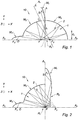
- such a geometric configuration of the three elliptical mirrors allows a high number (relative to the state of the art) of paths of the light beam inside the optical cavity according to the invention, between the light source and the detector, while maintaining a compact optical cavity.
- the properties of an ellipse lead to a flattening of the light rays propagating by the focal points.
- the light rays can thus travel the greatest possible distance inside the optical cavity.
- the light source is intended to be positioned at the focus of the first elliptical mirror distinct from F and the detector is intended to be positioned at the focus of the third elliptical mirror distinct from F.
- the optical cavity according to the invention is a pendular cavity in the sense that the light rays reflected successively by the second Elliptical mirror move between one end and the opposite end of the second elliptical mirror, while flattening.
- the cavity according to the invention can include one or more of the following characteristics.
- a 2 and A 3 are combined.
- an advantage obtained is the possibility for the third elliptical mirror to reflect the grazing light rays leaving the second elliptical mirror towards the detector.
- the half-line FA 3 intended to be oriented towards the detector, and the half-line FA 1 , intended to be oriented towards the light source, form an angle, denoted ⁇ , between 45 ° and 120 °.
- the angle ⁇ is between 45 ° and 90 °, preferably equal to 90 °.
- an advantage provided by the range [45 ° -90 °] over the range [45 ° -120 °] is to obtain a more compact optical cavity.
- an advantage provided by the angle ⁇ equal to 90 ° is to maximize the distance traveled by the light rays inside the optical cavity.
- the cavity according to the invention comprises a second reflector arranged to reflect the light radiation leaving the second elliptical mirror towards the first reflector; the first reflector being arranged to reflect the light radiation leaving the second reflector towards the third elliptical mirror.
- an advantage provided by the second reflector is to replace part of the second elliptical mirror.
- the second reflector is a plane mirror.
- an advantage provided by such a dimension d 2 is to ensure the reception of a maximum of light rays leaving the second elliptical mirror, in order to return them to the first reflector.
- the value d 2 b 2 2 at allows the first elliptical mirror to collect a maximum of light rays coming from the light source, when the light source is not directive.
- the first reflector is a plane mirror.
- the first reflector extends along A 2 , and has a dimension, denoted d 1 , along A 2 verifying: d 1 ⁇ 2 vs where c is the distance between the center of the second elliptical mirror and the common focus F.
- an advantage provided by such a dimension d 1 is to ensure the reception of a maximum of light rays exiting from the first elliptical mirror, from the second elliptical mirror, and where appropriate from the second reflector.
- the second elliptical mirror has an ellipticity ⁇ verifying 0 ⁇ ⁇ 0.25.
- an advantage provided by such an elliptical mirror is the possibility of improving the folding of the optical cavity, in other words the number of paths of the light rays inside the optical cavity after successive reflections.
- Such an elliptical mirror tends towards a behavior of a spherical mirror when ⁇ tends towards 0.
- the foci of the elliptical mirror are not merged in order to maintain a pendular cavity in the sense that the light rays reflected successively by the second elliptical mirror move between one end and the opposite end of the second elliptical mirror, while flattening.
- the optical cavity comprises two opposite reflecting ends, adapted to reflect the light radiation, and arranged on either side of the first, second and third elliptical mirrors as well as of the first reflector so as to form a waveguide.
- transverse is meant a direction perpendicular to the direction (denoted Z) along the thickness of the optical cavity.
- the section plane is denoted (X, Y) in the figures and corresponds to the plane of the optical cavity.
- a 2 and A 3 are advantageously combined.
- the planes in which the focal points of the second and third elliptical mirrors M 2 , M 3 extend are advantageously coincident.
- the foci of the second and third elliptical mirrors M 2 , M 3 are advantageously coplanar.
- the focal points F, F 2 of the second elliptical mirror M 2 and the focal points F, F 3 of the third elliptical mirror M 3 advantageously extend in the plane (X, Z).
- the half-line FA 3 intended to be oriented towards the detector D, and the half-line FA 1 , intended to be oriented towards the light source S, advantageously form an angle, denoted by ⁇ , between 45 ° and 120 °.
- the planes in which extend the foci of the third and first elliptical mirrors M 3 , M 1 form a dihedral angle ⁇ , comprised between 45 ° and 120 °.
- the angle ⁇ is advantageously between 45 ° and 90 °, preferably equal to 90 °.
- the plane (X, Z) in which extend the foci F, F 3 of the third elliptical mirror M 3 preferably forms a dihedral angle equal to 90 ° with the plane (Y, Z) in which are the foci F, F 1 of the first elliptical mirror M 1 .
- the first elliptical mirror M 1 can collect a maximum of light rays coming from the light source S (when the light source S is not directive), and this without reflecting the light radiation 2 exiting the first part of the second mirror elliptical M 2 .
- the first elliptical mirror M 1 can be arranged relative to the second elliptical mirror M 2 so that d 2 > b 2 2 at , with the drawback of a loss of the number of light rays received by the first elliptical mirror M 1 when the light source S is not directive (eg isotropic) such as a source thermal.
- This drawback can be overcome by using a directional light source S such as a quantum cascade laser.
- the dimensions (a, b) of the ellipses of the first, second and third elliptical mirrors M 1 , M 2 , M 3 are collated in the table below: where "a” is the semi-major axis, “b” is the semi-minor axis.
- the dimensions (a, b, c) of the ellipses of the first, second and third elliptical mirrors M 1 , M 2 , M 3 are chosen in particular as a function of the desired interaction length l between the fluid and the light radiation 2 when l
- the envisaged application is a fluid sensor.
- Each elliptical mirror M 1 , M 2 , M 3 advantageously has a coefficient of reflection of light radiation 2 greater than or equal to 75% for any angle of incidence.
- Said reflection coefficient is advantageously greater than or equal to 80%, preferably greater than or equal to 85%, more preferably greater than or equal to 90%, for any angle of incidence.
- the reflection coefficient of the light radiation 2 is greater than or equal to 95%, preferably greater than or equal to 98% for any angle of incidence less than 45 °.
- reflection coefficient means the intensity reflection coefficient, for an angle of incidence between 0 ° (normal incidence) and 90 ° (grazing incidence), for a given wavelength, and taking into account the polarizations "s" and "p" averaged arithmetically when the light source S is a thermal source.
- the angle of incidence is the angle between the direction of propagation of the light radiation 2 and the normal to the reflecting surface of the corresponding elliptical mirror.
- the second elliptical mirror M 2 advantageously has an ellipticity ⁇ verifying 0 ⁇ ⁇ 0.25.
- the optical cavity 1 is advantageously devoid of lenses.
- the first reflector R 1 is advantageously a plane mirror.
- the first reflector R 1 preferably extends along A 2 , and has a dimension, denoted d 1 , along A 2 verifying: d 1 ⁇ 2 vs where c is the distance between the center of the second elliptical mirror and the common focus F.
- the first reflector R 1 is arranged to reflect the light radiation 2 coming directly from the second elliptical mirror M 2 towards the third elliptical mirror M 3 .
- the first reflector R 1 is arranged to return the light radiation 2 leaving directly from the second elliptical mirror M 2 towards the second elliptical mirror M 2 until the light radiation 2 reaches the third elliptical mirror M 3 .
- the successive reflections of the light radiation 2 within the second elliptical mirror M 2 via the first reflector R 1 may be qualified as pendular reflections.
- the light rays reflected successively by the second elliptical mirror M 2 and by the first reflector R 1 move between one end and the opposite end of the second elliptical mirror M 2 , while flattening.
- the optical cavity 1 advantageously comprises a second reflector R 2 arranged to reflect the light radiation 2 leaving the second elliptical mirror M 2 towards the first reflector R 1 .
- the first reflector R 1 is then arranged to reflect the light radiation 2 leaving the second reflector R 2 towards the third elliptical mirror M 3 .
- the first reflector R 1 is arranged to reflect the light radiation 2 leaving indirectly (ie after reflection with the second reflector R 2 ) from the second elliptical mirror M 2 towards the third elliptical mirror M 3 .
- the dimension d 2 corresponds to the distance d 2 between I 1 and the second focal axis A 2 in the first embodiment illustrated in figure 1 .
- the second reflector R 2 can be arranged so that d 2 > b 2 2 at , with the drawback of a loss in the number of light rays received by the first elliptical mirror M 1 when the light source S is not directive (eg isotropic) such as a thermal source.
- This drawback can be overcome by using a directional light source S such as a quantum cascade laser.
- Each reflecting end has a reflecting surface having a reflection coefficient of light radiation 2 greater than or equal to 80%, preferably greater than or equal to 85%, more preferably greater than or equal to 90%, for any angle of incidence.
- the reflection coefficient of the light radiation 2 is greater than or equal to 95%, preferably greater than or equal to 98% for any angle of incidence less than 45 °.
- the term “reflection coefficient” means the intensity reflection coefficient, for an angle of incidence between 0 ° (normal incidence) and 90 ° (grazing incidence), for a given wavelength, and taking into account the polarizations "s" and "p" averaged arithmetically when the light source S is a thermal source.
- the angle of incidence is the angle between the direction of propagation of the light radiation 2 and the normal to the reflecting surface of the corresponding reflecting end.
- the reflecting surface of each reflecting end is preferably flat. The reflective, flat surfaces of the reflecting ends are advantageously parallel.
- each reflecting end is preferably made of a metallic material.
- the metallic material is preferably selected from the group comprising gold, silver, aluminum and copper.
- the reflecting surface of each reflecting end is advantageously coated with a protective layer against corrosion of the metallic material.
- the protective layer is advantageously made of a material selected from the group comprising SiO 2 , SiN, Si 3 N 4 , an amorphous DLC carbon (for the acronym Diamond-like carbon in English), polytetrafluoroethylene (PTFE), Pt , TiN.
- the two reflecting ends are preferably each made in the form of a plate.
- the plates are advantageously provided with openings shaped to receive the light source S and the detector D when the plates are brought into contact and fixed together.
- the two reflecting ends advantageously form plane mirrors.
- Step b) is advantageously carried out by deep reactive ionic etching.
- Step b) preferably comprises a preliminary step consisting in depositing a photosensitive resin on the surface of the first and second substrates. Then the recesses can be obtained by steps of photolithography and etching. Step b) is advantageously carried out so that the recesses obtained make it possible to form flat bottoms.
- the fact of hollowing out two substrates, instead of just one, during step b) makes it possible to increase the thickness of the optical cavity 1 formed during step c) in order to reduce optical losses by reflection .
- the reflecting surface of the reflecting ends is advantageously formed by depositing a metallic material on the bottoms of the first and second substrates, the deposit preferably being carried out by sputtering.
- the deposition of the metallic material can also be carried out by vacuum evaporation or by electrolysis.
- the deposition of the metallic material is carried out before step c).
- the reflecting surfaces of the elliptical mirrors M 1 , M 2 , M 3 and of the reflectors R 1 , R 2 are advantageously formed by depositing a metallic material on a lateral edge of a surface part, the deposit preferably being carried out by sputtering.
- the deposition of the metallic material can also be carried out by vacuum evaporation or by electrolysis. The deposition of the metallic material is carried out before step c).
- the recesses of the first and second substrates obtained during step b) make it possible to obtain two half-cavities.
- the optical cavity 1 is formed during step c) by assembling the first and second substrates in order to join the two half-cavities.
- the fact of forming a recess, for example by reactive ionic etching, in a substrate of a semiconductor material is an inexpensive and viable solution because the inclination obtained from the surface parts relative to the normal to the first and second substrates is typically of the order of 1 ° to 2 °.
- Step a) is preferably carried out so that the first and second molds each comprise a fixed part and a movable part.
- Step b) is preferably carried out with an injection molding machine.
- the reflecting surface of the reflecting ends is advantageously formed by depositing a metallic material on the bases of the first and second substrates, the deposit preferably being carried out by cathodic sputtering.
- the deposition of the metallic material can also be carried out by vacuum evaporation or by electrolysis. The deposition of the metallic material is carried out before step c).
- the reflecting surfaces of the elliptical mirrors M 1 , M 2 , M 3 and of the reflectors R 1 , R 2 are advantageously formed by depositing a metallic material on a lateral edge of a surface part, the deposit preferably being carried out by sputtering.
- the deposition of the metallic material can also be carried out by vacuum evaporation or by electrolysis. The deposition of the metallic material is carried out before step c).
- the optical cavity 1 is formed during step c) by assembling the first and second parts in order to join two half-cavities each delimited by the base and the corresponding surface part.
- Plastic injection is an inexpensive and viable solution insofar as the shape defects are not detrimental to correctly image the light source S on the detector D.
- the spectroscopic sensor 10 can also be a particle sensor, or a biological sensor.
- the light source S preferentially emits in the visible.
- the light source S can be of the LED type.
- the principle of operation is as follows.
- the particles generate waves scattered in the optical cavity 1 at random angles, which will not be refocused as far as the detector D due to successive absorptions in particular by the elliptical mirrors M 1 , M 2 , M 3 .
- This loss of transmission measured by the detector D is indicative of the type (index, size) and of the concentration of the particles insofar as the particles are generally not intrinsically absorbent.
- the light source S can be a thermal source or a quantum cascade laser.
- the light source S can be an infrared source.
- the light source S advantageously comprises an element, for example of the filament type, in which an electric current is circulated so that the element heats up and emits infrared radiation.
- the element has a dimension, noted e, according to the thickness of the optical cavity 1 preferably satisfying: 100 ⁇ m ⁇ e ⁇ E ⁇ 1.5 mm , more preferably 250 ⁇ m ⁇ e ⁇ E ⁇ 1200 ⁇ m where E is the thickness of optical cavity 1.
- the element preferably has the shape of a disc having a circular surface, with a diameter of 250 ⁇ m (corresponding to the dimension e).
- the axis of the light source S is defined as the normal to the circular surface.
- the disc may have a thickness of 400 nm along the axis of the light source S.
- the image of the light source S (ie the disc-shaped element) is a rectangle having a width of 250 ⁇ m and a height of 600 ⁇ m (the height corresponding to the direction Z according to the thickness of the optical cavity 1).
- Detector D can be an infrared detector.
- the infrared detector can be, for example, a bolometer or a pyrometer.
- the infrared detector may have an infrared sensitive surface.
- the sensitive surface may have the shape of a square with a side of 600 ⁇ m.
- the detector D is preferably equipped with an optical filter of the band-pass type, centered on the spectral absorption band of the gas to be detected, if applicable, when the light source S is a thermal source.
- the detector D advantageously extends along Z, over the entire thickness of the optical cavity 1, in order to receive a maximum of light radiation, the conjugation of the foci of the elliptical mirrors M 1 , M 2 , M 3 being imperfect along Z.
Landscapes
- Physics & Mathematics (AREA)
- General Physics & Mathematics (AREA)
- Optics & Photonics (AREA)
- Spectroscopy & Molecular Physics (AREA)
- Health & Medical Sciences (AREA)
- Life Sciences & Earth Sciences (AREA)
- Chemical & Material Sciences (AREA)
- Analytical Chemistry (AREA)
- Biochemistry (AREA)
- General Health & Medical Sciences (AREA)
- Immunology (AREA)
- Pathology (AREA)
- Investigating Or Analysing Materials By Optical Means (AREA)
- Lenses (AREA)
Claims (12)
- Optischer Hohlraum (1), umfassend:- einen ersten elliptischen Spiegel (M1), der eine erste Brennachse aufweist, die mit A1 bezeichnet ist, und die dazu bestimmt ist, eine Lichtstrahlung (2) zu reflektieren, welche von einer Lichtquelle (S) emittiert wird;- einen zweiten elliptischen Spiegel (M2), der eine zweite Brennachse aufweist, die mit A2 bezeichnet ist;- einen dritten elliptischen Spiegel (M3), der eine dritte Brennachse aufweist, die mit A3 bezeichnet ist, wobei die Lichtstrahlung (2), die aus dem dritten elliptischen Spiegel (M3) austritt, dazu bestimmt ist, von einem Detektor (D) empfangen zu werden;- einen ersten Reflektor (R1), der eingerichtet ist, um die Lichtstrahlung (2), die aus dem ersten elliptischen Spiegel (M1) austritt, zu dem zweiten elliptischen Spiegel (M2) zu reflektieren, und der eingerichtet ist, um die Lichtstrahlung (2), die aus dem zweiten elliptischen Spiegel (M2) austritt, zu dem dritten elliptischen Spiegel (M3) zu reflektieren;wobei der erste, zweite und dritte elliptische Spiegel (M1, M2, M3) derart eingerichtet sind, dass A1, A2 und A3 einen Schnittpunkt aufweisen, der mit F bezeichnet ist, und der einem Brennpunkt entspricht, den der erste, zweite und dritte elliptische Spiegel (M1, M2, M3) gemeinsam haben.
- Optischer Hohlraum (1) nach Anspruch 1, wobei A2 und A3 zusammenfallen.
- Optischer Hohlraum (1) nach Anspruch 1 oder 2, wobei die Halbgerade FA3, die dazu bestimmt ist, zu dem Detektor (D) orientiert zu sein, und die Halbgerade FA1, die dazu bestimmt ist, zu der Lichtquelle (S) orientiert zu sein, einen Winkel, der mit α bezeichnet ist, zwischen 45° und 120° bilden.
- Optischer Hohlraum (1) nach Anspruch 3, wobei der Winkel α zwischen 45° und 90°, vorzugsweise gleich 90° ist.
- Optischer Hohlraum (1) nach einem der Ansprüche 1 bis 4, umfassend einen zweiten Reflektor (R2), der eingerichtet ist, um die Lichtstrahlung (2), die aus dem zweiten elliptischen Spiegel (M2) austritt, zu dem ersten Reflektor (R1) zu reflektieren; wobei der erste Reflektor (R1) eingerichtet ist, um die Lichtstrahlung (2), die aus dem zweiten Reflektor (R2) austritt, zu dem dritten elliptischen Spiegel (M3) zu reflektieren.
- Optischer Hohlraum (1) nach Anspruch 5, wobei der zweite Reflektor (R2) ein planarer Spiegel ist.
- Optischer Hohlraum (1) nach Anspruch 5 oder 6, wobei sich der zweite Reflektor (R2) in der Verlängerung des ersten elliptischen Spiegels (M1) in einer Längsrichtung parallel zu A1 erstreckt und eine Abmessung, die mit d2 bezeichnet ist, in der Längsrichtung und von der zweiten Brennachse (A2) aufweist, und die entspricht:
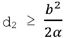 - a die große Halbachse des zweiten elliptischen Spiegels (M2) ist,- b die kleine Halbachse des zweiten elliptischen Spiegels (M2) ist.
 - Optischer Hohlraum (1) nach einem der Ansprüche 1 bis 7, wobei der erste Reflektor (R1) ein planarer Spiegel ist.
- Optischer Hohlraum (1) nach einem der Ansprüche 1 bis 8, wobei sich der erste Reflektor (R1) gemäß A2 erstreckt und eine Abmessung, die als d1 bezeichnet ist, gemäß A2 aufweist, und die entspricht:

- Optischer Hohlraum (1) nach einem der Ansprüche 1 bis 9, wobei der zweite elliptische Spiegel (M2) eine Elliptizität ε aufweist, die entspricht: 0<ε<0,25.
- Optischer Hohlraum (1) nach einem der Ansprüche 1 bis 10, umfassend zwei gegenüberliegende reflektierende Enden, die dafür geeignet sind, um die Lichtstrahlung (2) zu reflektieren, und die auf beiden Seiten des ersten, zweiten und dritten elliptischen Spiegels (M1, M2, M3) sowie des ersten Reflektors (R1) eingerichtet sind, um einen Wellenleiter zu bilden.
- Spektroskopischer Sensor (10), umfassend:- einen optischen Hohlraum (1) nach einem der Ansprüche 1 bis 11; wobei der erste elliptische Spiegel (M1) einen Brennpunkt aufweist, der mit F1 bezeichnet ist, und der von dem gemeinsamen Brennpunkt F verschieden ist; wobei der dritte elliptische Spiegel (M3) einen Brennpunkt aufweist, der mit F3 bezeichnet ist, und der von dem gemeinsamen Brennpunkt F verschieden ist;- eine Lichtquelle (S), die dafür geeignet ist, um eine Lichtstrahlung (2) zu emittieren, und die im Brennpunkt F1 eingerichtet ist;- einen Detektor (D), der im Brennpunkt F3 eingerichtet ist, um die Lichtstrahlung (2) zu empfangen, die aus dem dritten elliptischen Spiegel (M3) austritt.
Applications Claiming Priority (2)
| Application Number | Priority Date | Filing Date | Title |
|---|---|---|---|
| FR1659812A FR3057363B1 (fr) | 2016-10-11 | 2016-10-11 | Cavite optique pendulaire a fort repliement. |
| PCT/FR2017/052768 WO2018069624A1 (fr) | 2016-10-11 | 2017-10-10 | Cavite optique pendulaire a fort repliement |
Publications (2)
| Publication Number | Publication Date |
|---|---|
| EP3526585A1 EP3526585A1 (de) | 2019-08-21 |
| EP3526585B1 true EP3526585B1 (de) | 2020-11-25 |
Family
ID=58347463
Family Applications (1)
| Application Number | Title | Priority Date | Filing Date |
|---|---|---|---|
| EP17787512.7A Active EP3526585B1 (de) | 2016-10-11 | 2017-10-10 | Hochfaltender pendelartiger optischer resonator |
Country Status (4)
| Country | Link |
|---|---|
| US (1) | US10884225B2 (de) |
| EP (1) | EP3526585B1 (de) |
| FR (1) | FR3057363B1 (de) |
| WO (1) | WO2018069624A1 (de) |
Families Citing this family (2)
| Publication number | Priority date | Publication date | Assignee | Title |
|---|---|---|---|---|
| DE102018215587A1 (de) | 2018-09-13 | 2020-03-19 | Osram Opto Semiconductors Gmbh | Strahlleitende kavitätsstrukur, gassensor und verfahren zum herstellen der derselben |
| FR3095517B1 (fr) * | 2019-04-25 | 2021-05-14 | Elichens | Capteur de gaz compact |
Family Cites Families (28)
| Publication number | Priority date | Publication date | Assignee | Title |
|---|---|---|---|---|
| US3748014A (en) * | 1971-12-22 | 1973-07-24 | Columbia Broadcasting Sys Inc | Near-confocal device for optical scan enhancement |
| US4058699A (en) * | 1975-08-01 | 1977-11-15 | Arthur D. Little, Inc. | Radiant zone heating apparatus and method |
| US5546222A (en) * | 1992-11-18 | 1996-08-13 | Lightwave Electronics Corporation | Multi-pass light amplifier |
| US5615043A (en) * | 1993-05-07 | 1997-03-25 | Lightwave Electronics Co. | Multi-pass light amplifier |
| US5440143A (en) * | 1994-02-25 | 1995-08-08 | On-Line Technologies, Inc. | Folded-path optical analysis gas cell |
| GB9616809D0 (en) * | 1996-08-10 | 1996-09-25 | Eev Ltd | Gas monitors |
| US5880834A (en) * | 1996-10-16 | 1999-03-09 | The United States Of America As Represented By The Administrator Of The National Aeronautics And Space Administration | Convex diffraction grating imaging spectrometer |
| SE522941C2 (sv) * | 2000-04-26 | 2004-03-16 | Senseair Ab | Gascell |
| US7215428B2 (en) * | 2005-04-08 | 2007-05-08 | Ion Optics, Inc. | Absorption spectroscopy apparatus and method |
| KR100576541B1 (ko) * | 2005-06-16 | 2006-05-03 | (주) 인바이런먼트 리딩 테크놀러지 | 비분산 적외선 가스 센서를 위한 광 공동 |
| US8462347B2 (en) * | 2005-09-30 | 2013-06-11 | Mks Instruments, Inc. | Method and apparatus for siloxane measurements in a biogas |
| US7535573B2 (en) * | 2006-02-23 | 2009-05-19 | Picarro, Inc. | Cavity enhanced optical spectroscopy with a cavity having a predetermined deviation from a mode degeneracy condition |
| US7648248B2 (en) * | 2007-01-16 | 2010-01-19 | Eiji Yafuso | Optical energy director using conic of rotation (CoR) optical surfaces and systems of matched CoRs in the claims |
| WO2008127648A1 (en) * | 2007-04-13 | 2008-10-23 | Ion Optics, Llc | Absorption spectroscopy apparatus and method |
| US7817274B2 (en) * | 2007-10-05 | 2010-10-19 | Jingyun Zhang | Compact spectrometer |
| US7936455B2 (en) * | 2007-10-05 | 2011-05-03 | Burt Jay Beardsley | Three mirror anastigmat spectrograph |
| EP2053708A1 (de) * | 2007-10-25 | 2009-04-29 | Rofin-Sinar UK Ltd | Gaslaservorrichtung |
| WO2009070459A1 (en) * | 2007-11-30 | 2009-06-04 | Jingyun Zhang | Miniature spectrometers working with cellular phones and other portable electronic devices |
| DE102008019600B4 (de) * | 2008-04-18 | 2021-03-04 | Fraunhofer-Gesellschaft zur Förderung der angewandten Forschung e.V. | Optische Vorrichtung in gestapelter Bauweise und Verfahren zur Herstellung derselben |
| WO2010056668A1 (en) * | 2008-11-11 | 2010-05-20 | Bae Systems Information And Electronic Systems Integration Inc. | Optical multiplexer/demultiplexer |
| US8390806B1 (en) * | 2009-05-21 | 2013-03-05 | Lockheed Martin Corporation | MEMS spectrometer and sensing systems therefrom |
| US8411268B2 (en) * | 2010-10-01 | 2013-04-02 | Raytheon Company | Two material achromatic prism |
| US9246300B2 (en) * | 2012-06-01 | 2016-01-26 | Ronald LaComb | Mode tailored spherical laser |
| DE102012210954B4 (de) * | 2012-06-27 | 2022-10-20 | Nico Correns | Spektrometeranordnung |
| US9546904B2 (en) * | 2013-03-15 | 2017-01-17 | P & P Optica Inc. | Apparatus and method for optimizing data capture and data correction for spectroscopic analysis |
| US9132448B2 (en) * | 2013-10-23 | 2015-09-15 | Miltec Corporation | Apparatus for radiant energy curing of a coating |
| FR3016214B1 (fr) | 2014-01-07 | 2019-09-06 | Commissariat A L'energie Atomique Et Aux Energies Alternatives | Detecteur optique d'un gaz |
| CN106568762B (zh) * | 2016-11-07 | 2019-08-06 | 中国科学院光电研究院 | 扫描式激光诱导光谱面范围分析检测系统 |
-
2016
- 2016-10-11 FR FR1659812A patent/FR3057363B1/fr not_active Expired - Fee Related
-
2017
- 2017-10-10 EP EP17787512.7A patent/EP3526585B1/de active Active
- 2017-10-10 WO PCT/FR2017/052768 patent/WO2018069624A1/fr not_active Ceased
- 2017-10-10 US US16/341,220 patent/US10884225B2/en active Active
Non-Patent Citations (1)
| Title |
|---|
| None * |
Also Published As
| Publication number | Publication date |
|---|---|
| WO2018069624A1 (fr) | 2018-04-19 |
| FR3057363B1 (fr) | 2019-05-24 |
| US20190258038A1 (en) | 2019-08-22 |
| EP3526585A1 (de) | 2019-08-21 |
| FR3057363A1 (fr) | 2018-04-13 |
| US10884225B2 (en) | 2021-01-05 |
Similar Documents
| Publication | Publication Date | Title |
|---|---|---|
| EP3208601B1 (de) | Nicht-dispersiver infrarotsensor zur detektion eines gases | |
| US20130081447A1 (en) | Substrate-Integrated Hollow Waveguide Sensors | |
| WO2018162848A1 (fr) | Capteur optique de gaz | |
| WO1999040399A1 (fr) | Polarimetre et procede de mesure correspondant | |
| EP2891877A1 (de) | Mini-Gassensor | |
| EP3494381B1 (de) | Absorptionskavität mit eingangs- und ausgangswellenleitern für einen biologischen oder chemischen sensor | |
| EP3526585B1 (de) | Hochfaltender pendelartiger optischer resonator | |
| CN117233091A (zh) | 具备正七边形光路的气体吸收池及相应的激光传感器 | |
| EP3959506B1 (de) | Kompakter gassensor | |
| EP3431964B1 (de) | Optischer hohlraum mit starker dynamik | |
| EP3701247B1 (de) | Kompakter gassensor | |
| EP2711686B1 (de) | Optischer Detektor eines Gases | |
| EP1920234B1 (de) | Optisches system mit mehrfachreflexion | |
| EP3971550B1 (de) | Optischer teilchendetektor und herstellungsverfahren | |
| CN105181605B (zh) | 一种基于布拉格反射效应的光谱仪 | |
| EP4226143B1 (de) | Für gassensoren optimierte infrarot-lichtquelle und verfahren zu ihrer herstellung | |
| EP4345446B1 (de) | Multispektrale reflexionsbildgebungsvorrichtung | |
| US20130055818A1 (en) | Pressure control in continuous plasma deposition processes | |
| EP2410238B1 (de) | Optischer Reflektor auf transparenter Scheibe mit Hinterschnitt | |
| EP2410237A1 (de) | Korrigierter Reflektor vom elliptischen Typ | |
| FR2741449A1 (fr) | Detecteur d'un rayonnement diffuse |
Legal Events
| Date | Code | Title | Description |
|---|---|---|---|
| STAA | Information on the status of an ep patent application or granted ep patent |
Free format text: STATUS: UNKNOWN |
|
| STAA | Information on the status of an ep patent application or granted ep patent |
Free format text: STATUS: THE INTERNATIONAL PUBLICATION HAS BEEN MADE |
|
| PUAI | Public reference made under article 153(3) epc to a published international application that has entered the european phase |
Free format text: ORIGINAL CODE: 0009012 |
|
| STAA | Information on the status of an ep patent application or granted ep patent |
Free format text: STATUS: REQUEST FOR EXAMINATION WAS MADE |
|
| 17P | Request for examination filed |
Effective date: 20190313 |
|
| AK | Designated contracting states |
Kind code of ref document: A1 Designated state(s): AL AT BE BG CH CY CZ DE DK EE ES FI FR GB GR HR HU IE IS IT LI LT LU LV MC MK MT NL NO PL PT RO RS SE SI SK SM TR |
|
| AX | Request for extension of the european patent |
Extension state: BA ME |
|
| DAV | Request for validation of the european patent (deleted) | ||
| DAX | Request for extension of the european patent (deleted) | ||
| GRAP | Despatch of communication of intention to grant a patent |
Free format text: ORIGINAL CODE: EPIDOSNIGR1 |
|
| STAA | Information on the status of an ep patent application or granted ep patent |
Free format text: STATUS: GRANT OF PATENT IS INTENDED |
|
| INTG | Intention to grant announced |
Effective date: 20200617 |
|
| GRAS | Grant fee paid |
Free format text: ORIGINAL CODE: EPIDOSNIGR3 |
|
| GRAA | (expected) grant |
Free format text: ORIGINAL CODE: 0009210 |
|
| STAA | Information on the status of an ep patent application or granted ep patent |
Free format text: STATUS: THE PATENT HAS BEEN GRANTED |
|
| AK | Designated contracting states |
Kind code of ref document: B1 Designated state(s): AL AT BE BG CH CY CZ DE DK EE ES FI FR GB GR HR HU IE IS IT LI LT LU LV MC MK MT NL NO PL PT RO RS SE SI SK SM TR |
|
| REG | Reference to a national code |
Ref country code: GB Ref legal event code: FG4D Free format text: NOT ENGLISH |
|
| REG | Reference to a national code |
Ref country code: CH Ref legal event code: EP |
|
| REG | Reference to a national code |
Ref country code: DE Ref legal event code: R096 Ref document number: 602017028415 Country of ref document: DE |
|
| REG | Reference to a national code |
Ref country code: AT Ref legal event code: REF Ref document number: 1338889 Country of ref document: AT Kind code of ref document: T Effective date: 20201215 |
|
| REG | Reference to a national code |
Ref country code: IE Ref legal event code: FG4D Free format text: LANGUAGE OF EP DOCUMENT: FRENCH |
|
| REG | Reference to a national code |
Ref country code: AT Ref legal event code: MK05 Ref document number: 1338889 Country of ref document: AT Kind code of ref document: T Effective date: 20201125 |
|
| REG | Reference to a national code |
Ref country code: NL Ref legal event code: MP Effective date: 20201125 |
|
| PG25 | Lapsed in a contracting state [announced via postgrant information from national office to epo] |
Ref country code: FI Free format text: LAPSE BECAUSE OF FAILURE TO SUBMIT A TRANSLATION OF THE DESCRIPTION OR TO PAY THE FEE WITHIN THE PRESCRIBED TIME-LIMIT Effective date: 20201125 Ref country code: RS Free format text: LAPSE BECAUSE OF FAILURE TO SUBMIT A TRANSLATION OF THE DESCRIPTION OR TO PAY THE FEE WITHIN THE PRESCRIBED TIME-LIMIT Effective date: 20201125 Ref country code: PT Free format text: LAPSE BECAUSE OF FAILURE TO SUBMIT A TRANSLATION OF THE DESCRIPTION OR TO PAY THE FEE WITHIN THE PRESCRIBED TIME-LIMIT Effective date: 20210325 Ref country code: NO Free format text: LAPSE BECAUSE OF FAILURE TO SUBMIT A TRANSLATION OF THE DESCRIPTION OR TO PAY THE FEE WITHIN THE PRESCRIBED TIME-LIMIT Effective date: 20210225 Ref country code: GR Free format text: LAPSE BECAUSE OF FAILURE TO SUBMIT A TRANSLATION OF THE DESCRIPTION OR TO PAY THE FEE WITHIN THE PRESCRIBED TIME-LIMIT Effective date: 20210226 |
|
| PG25 | Lapsed in a contracting state [announced via postgrant information from national office to epo] |
Ref country code: AT Free format text: LAPSE BECAUSE OF FAILURE TO SUBMIT A TRANSLATION OF THE DESCRIPTION OR TO PAY THE FEE WITHIN THE PRESCRIBED TIME-LIMIT Effective date: 20201125 Ref country code: IS Free format text: LAPSE BECAUSE OF FAILURE TO SUBMIT A TRANSLATION OF THE DESCRIPTION OR TO PAY THE FEE WITHIN THE PRESCRIBED TIME-LIMIT Effective date: 20210325 Ref country code: LV Free format text: LAPSE BECAUSE OF FAILURE TO SUBMIT A TRANSLATION OF THE DESCRIPTION OR TO PAY THE FEE WITHIN THE PRESCRIBED TIME-LIMIT Effective date: 20201125 Ref country code: PL Free format text: LAPSE BECAUSE OF FAILURE TO SUBMIT A TRANSLATION OF THE DESCRIPTION OR TO PAY THE FEE WITHIN THE PRESCRIBED TIME-LIMIT Effective date: 20201125 Ref country code: SE Free format text: LAPSE BECAUSE OF FAILURE TO SUBMIT A TRANSLATION OF THE DESCRIPTION OR TO PAY THE FEE WITHIN THE PRESCRIBED TIME-LIMIT Effective date: 20201125 Ref country code: BG Free format text: LAPSE BECAUSE OF FAILURE TO SUBMIT A TRANSLATION OF THE DESCRIPTION OR TO PAY THE FEE WITHIN THE PRESCRIBED TIME-LIMIT Effective date: 20210225 |
|
| REG | Reference to a national code |
Ref country code: LT Ref legal event code: MG9D |
|
| PG25 | Lapsed in a contracting state [announced via postgrant information from national office to epo] |
Ref country code: HR Free format text: LAPSE BECAUSE OF FAILURE TO SUBMIT A TRANSLATION OF THE DESCRIPTION OR TO PAY THE FEE WITHIN THE PRESCRIBED TIME-LIMIT Effective date: 20201125 |
|
| PG25 | Lapsed in a contracting state [announced via postgrant information from national office to epo] |
Ref country code: LT Free format text: LAPSE BECAUSE OF FAILURE TO SUBMIT A TRANSLATION OF THE DESCRIPTION OR TO PAY THE FEE WITHIN THE PRESCRIBED TIME-LIMIT Effective date: 20201125 Ref country code: CZ Free format text: LAPSE BECAUSE OF FAILURE TO SUBMIT A TRANSLATION OF THE DESCRIPTION OR TO PAY THE FEE WITHIN THE PRESCRIBED TIME-LIMIT Effective date: 20201125 Ref country code: EE Free format text: LAPSE BECAUSE OF FAILURE TO SUBMIT A TRANSLATION OF THE DESCRIPTION OR TO PAY THE FEE WITHIN THE PRESCRIBED TIME-LIMIT Effective date: 20201125 Ref country code: SM Free format text: LAPSE BECAUSE OF FAILURE TO SUBMIT A TRANSLATION OF THE DESCRIPTION OR TO PAY THE FEE WITHIN THE PRESCRIBED TIME-LIMIT Effective date: 20201125 Ref country code: RO Free format text: LAPSE BECAUSE OF FAILURE TO SUBMIT A TRANSLATION OF THE DESCRIPTION OR TO PAY THE FEE WITHIN THE PRESCRIBED TIME-LIMIT Effective date: 20201125 Ref country code: SK Free format text: LAPSE BECAUSE OF FAILURE TO SUBMIT A TRANSLATION OF THE DESCRIPTION OR TO PAY THE FEE WITHIN THE PRESCRIBED TIME-LIMIT Effective date: 20201125 |
|
| REG | Reference to a national code |
Ref country code: DE Ref legal event code: R097 Ref document number: 602017028415 Country of ref document: DE |
|
| PG25 | Lapsed in a contracting state [announced via postgrant information from national office to epo] |
Ref country code: DK Free format text: LAPSE BECAUSE OF FAILURE TO SUBMIT A TRANSLATION OF THE DESCRIPTION OR TO PAY THE FEE WITHIN THE PRESCRIBED TIME-LIMIT Effective date: 20201125 |
|
| PLBE | No opposition filed within time limit |
Free format text: ORIGINAL CODE: 0009261 |
|
| STAA | Information on the status of an ep patent application or granted ep patent |
Free format text: STATUS: NO OPPOSITION FILED WITHIN TIME LIMIT |
|
| PG25 | Lapsed in a contracting state [announced via postgrant information from national office to epo] |
Ref country code: AL Free format text: LAPSE BECAUSE OF FAILURE TO SUBMIT A TRANSLATION OF THE DESCRIPTION OR TO PAY THE FEE WITHIN THE PRESCRIBED TIME-LIMIT Effective date: 20201125 Ref country code: NL Free format text: LAPSE BECAUSE OF FAILURE TO SUBMIT A TRANSLATION OF THE DESCRIPTION OR TO PAY THE FEE WITHIN THE PRESCRIBED TIME-LIMIT Effective date: 20201125 Ref country code: IT Free format text: LAPSE BECAUSE OF FAILURE TO SUBMIT A TRANSLATION OF THE DESCRIPTION OR TO PAY THE FEE WITHIN THE PRESCRIBED TIME-LIMIT Effective date: 20201125 |
|
| 26N | No opposition filed |
Effective date: 20210826 |
|
| PG25 | Lapsed in a contracting state [announced via postgrant information from national office to epo] |
Ref country code: SI Free format text: LAPSE BECAUSE OF FAILURE TO SUBMIT A TRANSLATION OF THE DESCRIPTION OR TO PAY THE FEE WITHIN THE PRESCRIBED TIME-LIMIT Effective date: 20201125 |
|
| PG25 | Lapsed in a contracting state [announced via postgrant information from national office to epo] |
Ref country code: ES Free format text: LAPSE BECAUSE OF FAILURE TO SUBMIT A TRANSLATION OF THE DESCRIPTION OR TO PAY THE FEE WITHIN THE PRESCRIBED TIME-LIMIT Effective date: 20201125 |
|
| REG | Reference to a national code |
Ref country code: CH Ref legal event code: PL |
|
| PG25 | Lapsed in a contracting state [announced via postgrant information from national office to epo] |
Ref country code: IS Free format text: LAPSE BECAUSE OF FAILURE TO SUBMIT A TRANSLATION OF THE DESCRIPTION OR TO PAY THE FEE WITHIN THE PRESCRIBED TIME-LIMIT Effective date: 20210325 |
|
| REG | Reference to a national code |
Ref country code: BE Ref legal event code: MM Effective date: 20211031 |
|
| PG25 | Lapsed in a contracting state [announced via postgrant information from national office to epo] |
Ref country code: MC Free format text: LAPSE BECAUSE OF FAILURE TO SUBMIT A TRANSLATION OF THE DESCRIPTION OR TO PAY THE FEE WITHIN THE PRESCRIBED TIME-LIMIT Effective date: 20201125 |
|
| PG25 | Lapsed in a contracting state [announced via postgrant information from national office to epo] |
Ref country code: LU Free format text: LAPSE BECAUSE OF NON-PAYMENT OF DUE FEES Effective date: 20211010 Ref country code: BE Free format text: LAPSE BECAUSE OF NON-PAYMENT OF DUE FEES Effective date: 20211031 |
|
| PG25 | Lapsed in a contracting state [announced via postgrant information from national office to epo] |
Ref country code: LI Free format text: LAPSE BECAUSE OF NON-PAYMENT OF DUE FEES Effective date: 20211031 Ref country code: CH Free format text: LAPSE BECAUSE OF NON-PAYMENT OF DUE FEES Effective date: 20211031 |
|
| PG25 | Lapsed in a contracting state [announced via postgrant information from national office to epo] |
Ref country code: IE Free format text: LAPSE BECAUSE OF NON-PAYMENT OF DUE FEES Effective date: 20211010 |
|
| PG25 | Lapsed in a contracting state [announced via postgrant information from national office to epo] |
Ref country code: CY Free format text: LAPSE BECAUSE OF FAILURE TO SUBMIT A TRANSLATION OF THE DESCRIPTION OR TO PAY THE FEE WITHIN THE PRESCRIBED TIME-LIMIT Effective date: 20201125 |
|
| PG25 | Lapsed in a contracting state [announced via postgrant information from national office to epo] |
Ref country code: HU Free format text: LAPSE BECAUSE OF FAILURE TO SUBMIT A TRANSLATION OF THE DESCRIPTION OR TO PAY THE FEE WITHIN THE PRESCRIBED TIME-LIMIT; INVALID AB INITIO Effective date: 20171010 |
|
| PG25 | Lapsed in a contracting state [announced via postgrant information from national office to epo] |
Ref country code: MK Free format text: LAPSE BECAUSE OF FAILURE TO SUBMIT A TRANSLATION OF THE DESCRIPTION OR TO PAY THE FEE WITHIN THE PRESCRIBED TIME-LIMIT Effective date: 20201125 |
|
| PG25 | Lapsed in a contracting state [announced via postgrant information from national office to epo] |
Ref country code: TR Free format text: LAPSE BECAUSE OF FAILURE TO SUBMIT A TRANSLATION OF THE DESCRIPTION OR TO PAY THE FEE WITHIN THE PRESCRIBED TIME-LIMIT Effective date: 20201125 |
|
| PG25 | Lapsed in a contracting state [announced via postgrant information from national office to epo] |
Ref country code: MT Free format text: LAPSE BECAUSE OF FAILURE TO SUBMIT A TRANSLATION OF THE DESCRIPTION OR TO PAY THE FEE WITHIN THE PRESCRIBED TIME-LIMIT Effective date: 20201125 |
|
| PGFP | Annual fee paid to national office [announced via postgrant information from national office to epo] |
Ref country code: DE Payment date: 20251020 Year of fee payment: 9 |
|
| PGFP | Annual fee paid to national office [announced via postgrant information from national office to epo] |
Ref country code: GB Payment date: 20251029 Year of fee payment: 9 |
|
| PGFP | Annual fee paid to national office [announced via postgrant information from national office to epo] |
Ref country code: FR Payment date: 20251024 Year of fee payment: 9 |