EP3529565B1 - Système modulaire pour la construction d'un dispositif de mesure - Google Patents
Système modulaire pour la construction d'un dispositif de mesure Download PDFInfo
- Publication number
- EP3529565B1 EP3529565B1 EP17780307.9A EP17780307A EP3529565B1 EP 3529565 B1 EP3529565 B1 EP 3529565B1 EP 17780307 A EP17780307 A EP 17780307A EP 3529565 B1 EP3529565 B1 EP 3529565B1
- Authority
- EP
- European Patent Office
- Prior art keywords
- unit
- sensor
- assembly kit
- communication
- units
- Prior art date
- Legal status (The legal status is an assumption and is not a legal conclusion. Google has not performed a legal analysis and makes no representation as to the accuracy of the status listed.)
- Active
Links
Images


Classifications
-
- G—PHYSICS
- G01—MEASURING; TESTING
- G01D—MEASURING NOT SPECIALLY ADAPTED FOR A SPECIFIC VARIABLE; ARRANGEMENTS FOR MEASURING TWO OR MORE VARIABLES NOT COVERED IN A SINGLE OTHER SUBCLASS; TARIFF METERING APPARATUS; MEASURING OR TESTING NOT OTHERWISE PROVIDED FOR
- G01D21/00—Measuring or testing not otherwise provided for
- G01D21/02—Measuring two or more variables by means not covered by a single other subclass
-
- G—PHYSICS
- G01—MEASURING; TESTING
- G01D—MEASURING NOT SPECIALLY ADAPTED FOR A SPECIFIC VARIABLE; ARRANGEMENTS FOR MEASURING TWO OR MORE VARIABLES NOT COVERED IN A SINGLE OTHER SUBCLASS; TARIFF METERING APPARATUS; MEASURING OR TESTING NOT OTHERWISE PROVIDED FOR
- G01D11/00—Component parts of measuring arrangements not specially adapted for a specific variable
- G01D11/24—Housings ; Casings for instruments
- G01D11/245—Housings for sensors
Definitions
- the invention is concerned with measuring devices, in particular mobile hand-held devices, for measuring a measured variable.
- Such measuring devices usually have a sensor for detecting a physical or chemical measured variable and an interface for transmitting the measured value to an evaluation unit.
- This evaluation unit can be integrated into the measuring device.
- a display unit for displaying the measured value can also be integrated.
- Such a measuring device can be designed as a compact hand-held device so that it can be used flexibly at different measuring locations.
- a construction kit which comprises at least one evaluation unit, a communication unit and several sensor units which can be combined to form a measuring device in which individual units are inserted into a housing.
- a sensor which can be fastened to a mounting body, a telescopically extendable receiving device being arranged between the sensor and the mounting body.
- the object of the invention is to create a measuring device that can be used more flexibly and has fewer downtimes.
- the modular system according to the invention for building a measuring device comprises at least two sensor units, each designed to measure different physical or chemical variables, and at least two communication units, each having different interfaces for data transmission, each of the sensor units with each of the communication units of the modular system via a mechanical Coupling can be releasably connected and at least one extension unit with a housing that has mechanical couplings on both sides to which a sensor unit, a communication unit and / or another extension unit can optionally be coupled, the housing having a telescopic arrangement with which the extension unit can be changed in its longitudinal extent is.
- the idea of the invention is a separation of the various functional units of a measuring device into separate, modularly assemblable units.
- a measuring device can therefore be assembled from different modules of the construction kit.
- At least two sensor units are available in the construction kit, each of which is designed to detect a different physical or chemical measured variable.
- Such measured variables can be, for example, temperature, flow rate or a gas concentration.
- At least two communication units are available in the modular system, each of which has different interfaces via which the measurement results can be transmitted.
- Possible interfaces here are, for example, wireless interfaces such as WLAN, Bluetooth, Zigbee, NFC or the like.
- the interface can, however, also be wired and designed, for example, for connection to a field bus, for example Ethernet, Modbus, Profibus, or the like.
- the advantage of the invention is that the sensor units and the communication units of the construction kit can be combined with one another as desired, so that a measuring device adapted to the required environment in each case is pluggable.
- the individual modules are connected via a mechanical coupling.
- the further advantage is that in an application scenario for measuring different measured variables, for example, only one communication unit is required, which can be equipped with different sensor units for measuring different measured variables.
- the modular structure has the further advantage that if a sensor unit is defective, only this sensor unit has to be replaced. Likewise, only this sensor unit has to be given away for a calibration of the sensor unit. In any case, you can continue to measure with a different sensor unit.
- the modular design of the measuring device also has the advantage that the number of parts, the development effort and the testing effort are reduced.
- the modular system comprises at least one sensor unit which is designed to measure at least two different physical quantities and / or at least one communication unit which has at least two different interfaces for data transmission.
- the interfaces of the communication units are designed to establish a wireless and / or wired connection.
- one or the wireless interfaces is / are set up to select one or more wireless connections in each case of the group of WLAN, Bluetooth and / or Zigbee and / or wherein one or the wired interfaces is / are designed as a connection for a data transmission cable or as a data transmission cable.
- sensor electronics are arranged in a housing of the sensor unit and / or in a housing of the communication unit and / or that communication electronics are arranged in a housing of the sensor unit and / or in a housing of the communication unit. It is particularly expedient if sensor electronics are arranged in the sensor unit and communication electronics are arranged in the communication unit. In this way, a particularly cost-effective design of the modules according to the invention is possible.
- the mechanical coupling between a sensor unit and a communication unit is preferably designed in such a way that it establishes a secure and firm mechanical connection and can be quickly and easily established and released again. In this way, a simple and convenient exchange of the modules is possible. It is particularly useful if the mechanical coupling is designed as a plug-in coupling, screw coupling, latching connection, clamping connection and / or friction connection.
- each measuring device that can be assembled using the modular system has a handle.
- the handle allows easy and safe handling of the measuring device.
- the handle can be designed as a separate module, which can also be connected to a sensor unit or a communication unit via a mechanical coupling. It is particularly advantageous if the Handle designed by one or the housing of the sensor unit and / or by one or the housing of the communication unit and / or arranged thereon. In this way, a separate handle unit is not necessary.
- the handle can for example be formed by a rubber coating.
- the measured values recorded by the sensor unit are transmitted to a processing or display unit via the communication unit. It can be advantageous here for at least one communication unit and / or at least one sensor unit of the construction kit to have a display unit for displaying a measured value. In this way, the measured value can be viewed and checked immediately on the measuring device.
- At least one communication unit and / or at least one sensor unit of the construction kit has a processing unit for processing the measured values.
- the processing of measured values can include, for example, the calculation of dependent values, storage and / or linking with other measured values.
- the mechanical coupling between a sensor unit and a communication unit also requires an electrical connection to transmit the measured values from the sensor unit to the communication unit. It is particularly advantageous if the sensor units and the communication units can be detachably connected to one another via a plug-in coupling.
- the plug-in coupling can provide both the electrical and the mechanical connection, so that the coupling is particularly easy to handle.
- Either the sensor units can have a plug and the Communication units have a socket corresponding to the plug or the communication units have a plug and the sensor units have a socket corresponding to the plug.
- a uniform data protocol is used for electrical communication between the sensor units and the communication units. Strict adherence to this protocol ensures any combination option.
- a measured variable can also be transmitted in addition to the measured value. This enables measured value evaluation without knowing the currently used sensor beforehand.
- a measuring device assembled from the modular system can be used immediately.
- the individual modules in particular the sensor unit and / or the communication unit, can have configuration data that are exchanged during assembly.
- a communication unit can recognize which sensor unit it is currently connected to.
- the modular system can include a computer program product, in particular an app, which can be installed on a data processing device, by means of which computer program product a data transmission to the data processing device and / or a configuration of a measuring device assembled from the modular system, in particular the sensor unit and / or the communication unit, is feasible.
- a measuring device can be set up and put into operation in a convenient manner.
- there is also a Transfer of the measured values to this computer program product is possible.
- the computer program product thus provides a possibility of processing, storing and / or linking measured values.
- the existing sensor units can be managed with it, so that any necessary calibrations can be terminated and displayed.
- a sensor is arranged in a housing, the housing having a mechanical coupling for coupling a further unit to form a measuring device.
- the further unit is in particular part of a modular system according to the invention.
- the measuring device formed can be part of a series.
- a communication unit has at least one communication interface for data exchange with an external device and a housing, the housing having a mechanical coupling for coupling a further unit to form a measuring device.
- the further unit is in particular part of a modular system according to the invention.
- the measuring device formed can be part of a series.
- the construction kit has at least one extension unit with two mechanical couplings, wherein the extension unit can be coupled between a sensor unit and / or a communication unit and / or one or two further extension units and / or wherein at least one two-pole connection line between the couplings with rotationally symmetrical electrical connection means, in particular a jack plug and / or a jack socket.
- the extension unit is preferably coupled between a sensor unit and a communication unit in order, for example, to increase the total length of the measuring device and / or the range of the sensor.
- the extension unit has mechanical couplings that match the couplings of the sensor unit and the communication unit.
- the couplings can each have a bayonet lock, for example, with which the individual parts can be connected to one another in a mechanically fixed and detachable manner.
- the extension unit can each have a socket and a plug that match the plug of the sensor units or the socket of the communication units or the plug of the communication units or the socket of the sensor units.
- the extension unit In addition to the mechanical coupling, the extension unit also has an electrical coupling, so that there is an electrical connection between the sensor unit and the communication unit even if the extension unit is coupled between them. Inside the extension unit, the signal line takes place via a cable.
- the electrical interface can be designed, for example, in the form of clinker plugs, which enable rotation and which establish the electrical connection between the sensor unit and the communication unit.
- the electrical interface can also form the mechanical coupling.
- the jack plugs are preferably arranged centrally in order to to allow rotation to actuate a bayonet lock.
- the extension unit provides a telescopic system which can be transferred between a retracted and an extended position.
- the length can be adjusted continuously or, for example, in discrete locking steps.
- the extension unit can have a fixing device with which, for example, the extended position can be determined.
- the fixing device can be activated, for example, by rotating it about the longitudinal axis.
- the cable inside is designed as a helical line, which runs in a spiral and enables the excess line section to be twisted in the collapsed state inside.
- extension unit can be combined with itself in almost any way.
- mechanical couplings are provided on both sides, which are designed to correspond to one another in mirror-inverted fashion. In this way, several extension units can be coupled to one another in order to achieve a desired or required length.
- a series can be formed from several measuring devices, each measuring device having at least one sensor unit and at least one communication unit, and the individual measuring devices of the series being manufactured or assembled with the modular system according to the invention, in particular where at least two measuring devices have matching sensor units and communication units that differ from one another.
- the Fig. 1 shows an example of several sensor units 1 of the modular system according to the invention.
- the sensor units 1 each have a sensor 2 and matching sensor electronics 3.
- the sensor units 1 are set up to record different physical and / or chemical measured variables.
- the Fig. 1 (a) shows, for example, a sensor unit 1, for example for temperature measurement, with an angled shaft 4.
- Fig. 1 (b) shows a sensor unit 1 with a straight shaft 4.
- Fig. 1 (c) shows an example of a sensor unit 1 with a flow sensor with an impeller 5.
- the sensor units (a) to (c) have an integrated mechanical coupling 7 with which the sensor unit 1 is connected to a communication unit 6 (see FIG Fig. 2 ) is connectable.
- Fig. 1 (d) shows a to Fig. 1 (b) similar sensor unit 1.
- the Fig. 1 (e) shows a two-part sensor unit in which the sensor and the sensor electronics are each in a separate, housed connected by a connecting cable are arranged.
- Fig. 1 (e) shows a two-part sensor unit in which the sensor and the sensor electronics are each in a separate, housed connected by a connecting cable are arranged.
- Fig. 1 (e) shows a two-part sensor
- FIG. 1 (f) shows a further sensor unit 1, which, however, has two sensors 2 for detecting different physical and / or chemical variables.
- Fig. 1 (g) a sensor unit 1 for detecting moisture, for example in a masonry.
- the sensor units (d) to (g) each have a cable 8 with which the sensor unit 1 can be mechanically and electrically coupled to a communication unit 6.
- the Fig. 2 shows an example of several communication units 6 of the modular system according to the invention.
- the communication units 6 each have communication electronics 15, which can be designed differently depending on the interface.
- each communication unit 6 has a coupling 7 for coupling a sensor unit 1.
- This coupling 7 is designed both for direct coupling of a sensor unit 1 and for coupling a cable 8 of a sensor unit 1.
- the communication units 6 each have a socket with plug contacts (not shown) into which a suitable plug with plug contacts (not shown) can be inserted, which is either fixedly arranged on the sensor unit 1 or on a cable 8 of the sensor unit 1.
- a plug that fits into a socket of the sensor unit 1 or of the cable 8 can also be arranged on the communication units 6.
- the communication unit 6 of the Fig. 2 (a) is designed for wireless communication with a Bluetooth module, for example. While the communication unit 6 of the Fig. 2 (b) can communicate wirelessly via a Zigbee module 17.
- the communication unit 6 of the Fig. 2 (c) however, has a bus module 19 for wired communication via a cable 9 with a bus.
- the communication unit 6 has a display unit 10 for displaying measured values.
- the communication unit 6 of the Fig. 2 (d) however, has two independent communication interfaces, a WLAN module 18 and a Bluetooth module 16 for wireless communication.
- the communication unit of the Fig. 2 (d) has no interface for external communication. It has a display unit 10 for displaying measured values and a processing unit 20 for processing measured values. Such processing can be, for example, the formation of a mean value from several measured values, or the linking of two different measured variables from two sensors of a sensor unit as in FIG Fig. 1 (f) or involve other mathematical or statistical calculations. The processed value can then be displayed in the display unit 10.
- the modular system according to the invention is now formed from at least two different sensor units 1 and at least two different communication units 6 and at least one extension unit 12.
- a measuring device can now be manufactured by assembling a sensor unit 1 and a communication unit 6.
- a sensor unit 1 and / or a communication unit 6 can have a handle 11.
- the handle 11 can be formed, for example, by a housing 21 of a sensor unit 1 and / or a communication unit 6.
- the housing 21 can, for example, have a rubber coating or other handle parts that are connected to the housing 21.
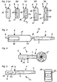
- the Figures 3 to 5 now show examples of different measuring devices that can be assembled with the kit.
- the measuring device 13 in Fig. 3 shows a sensor unit 1, for example Fig. 1 (b) and a communication unit 6 according to Fig. 2 (c) on.
- a sensor unit 1 for the measuring device 13 in Fig. 4 is a sensor unit 1 according to Fig. 1 (c) with a communication unit 6 according to Fig. 2 (a) assembled.
- the measuring device 13 in Fig. 5 consists of a sensor unit 1 according to Fig. 1 (d) and a communication unit 6 according to Fig. 2 (b) .
- the Fig. 6 a smartphone 14 or a tablet on which a computer program is loaded that is connected to the communication unit 6.
- the computer program 22 is set up, for example, to Configure measuring device 13 and / or display measured values and / or otherwise process measured values.
- the computer program 22 shows a temperature of the sensor 2 of the sensor unit 1.
- the modular system according to the invention contains one or more extension units 12.
- the Fig. 6 shows a schematic representation of various extension units 12 of a modular system according to the invention.
- the extension unit 12 of the Fig. 6 (a) has a telescopic arrangement 23, which allows a stepless change in length.
- the extension unit 12 has mechanical couplings 7 on both sides, which enable coupling to sensor and communication units.
- the telescopic arrangement 23 can also have means for fixing the telescopic position so that the length does not change during operation. This fixation can be done, for example, by an internal clamp that can be actuated by rotating the foremost telescope segment.
- the extension unit 12 of the Fig. 6 (b) however, has a fixed length.
- the mechanical couplings 7 at their ends are designed so that they are not only suitable for coupling with sensor and communication units. But also for coupling with further identical or different extension units 12. Two or more of these extension units 12 can thus be connected to one another in order to achieve a desired or required length.
- the kit can also have several extension units 12 with different fixed lengths.
- the Fig. 7 shows a measuring device 13 with a sensor unit 1 according to FIG Fig. 1 (d) and a communication unit 6 according to Fig. 2 (b) between which a telescopic extension unit 12 according to Fig. 6 (a) is coupled.
- the Fig. 8 shows the measuring device 13 with a sensor unit 1 Fig. 1 (d) and a communication unit 6 according to Fig. 2 (b) between which several telescopic extension units 12 according to Fig. 6 (b) are coupled.
Landscapes
- Physics & Mathematics (AREA)
- General Physics & Mathematics (AREA)
- Arrangements For Transmission Of Measured Signals (AREA)
Claims (10)
- Système modulaire pour la construction d'un dispositif de mesure (13), comprenant au moins deux unités de détection (1) qui sont conçues chacune pour la mesure de grandeurs différentes, au moins deux unités de communication (6) qui présentent chacune des interfaces différentes pour la transmission de données, chacune des unités de détection (1) pouvant être reliée à chacune des unités de communication (6) du système modulaire par un accouplement mécanique (7) et au moins une unité de rallonge (12) avec un boîtier (21) qui présente des deux côtés des accouplements mécaniques (7) pouvant être accouplée au choix à une unité de détection (1), à une unité de communication (6) et/ou à une autre unité de rallonge (12), caractérisé en ce que le boîtier (21) présente un dispositif télescopique (23) avec lequel l'unité de rallonge (12) peut être modifiée dans son extension longitudinale.
- Système modulaire selon la revendication 1, caractérisé en ce que ce système modulaire comprend au moins une unité de détection (1) qui est conçue pour la mesure d'au moins deux grandeurs différentes et/ou que ce système modulaire comprend au moins une unité de communication (6) qui présente au moins deux interfaces différentes pour la transmission de données.
- Système modulaire selon la revendication 1 ou 2, caractérisé en ce que les interfaces des unités de communication (6) sont conçues pour l'établissement d'une liaison sans fil et/ou filaire, de préférence une ou les interface(s) sans fil étant équipée(s) pour établir chacune une ou plusieurs liaisons sans fil sélectionnées parmi le groupe comprenant le WLAN (18), Bluetooth (16) et/ou Zigbee (17), et/ou une ou les interface(s) sans fil (19) étant configurée(s) comme un branchement pour un câble de transmission de données (9) ou comme un câble de transmission de données (9).
- Système modulaire selon une des revendications 1 à 3, caractérisé en ce qu'un système électronique de détection (3) est disposé dans un boîtier (21) de l'unité de détection (1) et/ou dans un boîtier (21) de l'unité de communication (6) et/ou qu'un système électronique de communication (15) est disposé dans un boîtier (21) de l'unité de détection (1) et/ou dans un boîtier (21) de l'unité de communication (6).
- Système modulaire selon une des revendications 1 à 4, caractérisé en ce que l'accouplement mécanique (7) est configuré comme un accouplement à enfichage, un accouplement à vis, une liaison à encliquetage, une liaison à serrage et/ou une liaison à friction.
- Système modulaire selon une des revendications 1 à 5, caractérisé en ce que chaque dispositif de mesure (13) pouvant être assemblé par le biais du système modulaire présente une poignée (11), en particulier dans lequel la poignée (11) est constituée par un ou le boîtier (21) de l'unité de détection (1) et/ou par un ou le boîtier (21) de l'unité de communication (6) et/ou est disposée dessus.
- Système modulaire selon une des revendications 1 à 6, caractérisé en ce qu'au moins une unité de communication (6) et/ou au moins une unité de détection (1) du système modulaire présentent une unité d'affichage (10) pour l'affichage d'une valeur de mesure et/ou qu'au moins une unité de communication (6) et/ou au moins une unité de détection (1) du système modulaire présentent une unité de traitement (20) pour le traitement de valeurs de mesure.
- Système modulaire selon une des revendications 1 à 7, caractérisé en ce que les unités de détection (1) et les unités de communication (6) peuvent être reliées entre elles de façon amovible par un accouplement à enfichage (7), dans lequel les unités de détection (1) présentent une fiche et les unités de communication (6) une prise correspondant à la fiche et/ou dans lequel les unités de communication (6) présentent une fiche et les unités de détection (1) une prise correspondant à la fiche.
- Système modulaire selon une des revendications 1 à 8, caractérisé en ce que ce système modulaire comprend un programme informatique (22) pouvant être installé sur un appareil de traitement de données (14), en particulier une application, au moyen duquel programme informatique une transmission de données à l'appareil de transmission de données et/ou une configuration d'un dispositif de mesure (13) assemblé à partir du système modulaire, en particulier de l'unité de détection (1) et/ou de l'unité de communication (6), peuvent être réalisées.
- Système modulaire selon une des revendications 1 à 9, caractérisé en ce que l'au moins une ou une autre unité de rallonge (12), au moins un câble de liaison bipolaire, est reliée entre les accouplements (7) avec des moyens de liaison électrique symétriques en rotation, en particulier une fiche jack et/ou une prise jack.
Applications Claiming Priority (2)
| Application Number | Priority Date | Filing Date | Title |
|---|---|---|---|
| DE102016012567.5A DE102016012567A1 (de) | 2016-10-21 | 2016-10-21 | Baukasten zum Bau einer Messvorrichtung |
| PCT/EP2017/001168 WO2018072864A1 (fr) | 2016-10-21 | 2017-10-04 | Système modulaire pour la construction d'un dispositif de mesure |
Publications (2)
| Publication Number | Publication Date |
|---|---|
| EP3529565A1 EP3529565A1 (fr) | 2019-08-28 |
| EP3529565B1 true EP3529565B1 (fr) | 2021-12-08 |
Family
ID=60022043
Family Applications (1)
| Application Number | Title | Priority Date | Filing Date |
|---|---|---|---|
| EP17780307.9A Active EP3529565B1 (fr) | 2016-10-21 | 2017-10-04 | Système modulaire pour la construction d'un dispositif de mesure |
Country Status (4)
| Country | Link |
|---|---|
| US (1) | US11105663B2 (fr) |
| EP (1) | EP3529565B1 (fr) |
| DE (1) | DE102016012567A1 (fr) |
| WO (1) | WO2018072864A1 (fr) |
Families Citing this family (3)
| Publication number | Priority date | Publication date | Assignee | Title |
|---|---|---|---|---|
| DE102018118933A1 (de) * | 2018-08-03 | 2020-02-06 | Testo SE & Co. KGaA | Messgerät, Baureihe und Verwendung eines Kommunikationsgeräts |
| DE102020105213A1 (de) | 2020-02-27 | 2021-09-02 | Endress + Hauser Wetzer Gmbh + Co. Kg | Feldgerät-Elektronik |
| DE102022108725B4 (de) * | 2022-04-11 | 2023-11-09 | SmartRay GmbH | Optische Prüfvorrichtung sowie Baukasten zu seiner Erstellung |
Family Cites Families (13)
| Publication number | Priority date | Publication date | Assignee | Title |
|---|---|---|---|---|
| EP1529198B1 (fr) * | 2002-08-13 | 2020-02-26 | VEGA Grieshaber KG | Systeme pour realiser un dispositif de structure modulaire qui sert a determiner une grandeur de processus physique, et composants normalises |
| DE102007053833A1 (de) * | 2007-11-12 | 2009-05-14 | Siemens Ag | Modulare Station eines Automatisierungssystems |
| DE102010038734A1 (de) * | 2010-07-30 | 2012-02-02 | Testo Ag | Messsonde zum Eintauchen in eine Messkammer bzw. einen Messkanal |
| DE102011001214B4 (de) * | 2011-03-11 | 2017-01-26 | JUMTEC GmbH & Co. KG | Universales Messgerät |
| DE102012110167B4 (de) * | 2012-10-24 | 2014-06-18 | Sick Ag | Sensor |
| TWI651621B (zh) * | 2013-12-18 | 2019-02-21 | 財團法人國家實驗研究院 | 具有可重組模組化感測裝置的感測系統及該感測系統的初始方法 |
| ES2732556T3 (es) * | 2014-02-12 | 2019-11-25 | Alcatel Lucent | Sistema de sensor modular, método, módulo sensor y producto de programa informático |
| DE102014106935B4 (de) * | 2014-05-16 | 2022-01-13 | Sick Ag | Modulares Sensorsystem |
| US11274940B2 (en) * | 2018-06-08 | 2022-03-15 | Koepke InnoTek Ltd. T/A Motoklik | Suspension position monitoring system |
| CN110836681A (zh) * | 2018-08-16 | 2020-02-25 | 国网冀北电力有限公司张家口供电公司 | 一种变电站交流电源监测装置 |
| CN210665096U (zh) * | 2019-09-12 | 2020-06-02 | 广东穗安科技检测中心有限公司 | 一种新型建筑消防设备电子维保检测装置 |
| CN211178587U (zh) * | 2019-12-26 | 2020-08-04 | 北京华电云通电力技术有限公司 | 智慧工地噪声监管装置 |
| CN211317375U (zh) * | 2020-01-10 | 2020-08-21 | 江苏北电兴发科技有限公司 | 一种环境监控检测装置 |
-
2016
- 2016-10-21 DE DE102016012567.5A patent/DE102016012567A1/de not_active Ceased
-
2017
- 2017-10-04 EP EP17780307.9A patent/EP3529565B1/fr active Active
- 2017-10-04 WO PCT/EP2017/001168 patent/WO2018072864A1/fr not_active Ceased
- 2017-10-04 US US16/339,563 patent/US11105663B2/en active Active
Non-Patent Citations (1)
| Title |
|---|
| None * |
Also Published As
| Publication number | Publication date |
|---|---|
| US20200041317A1 (en) | 2020-02-06 |
| DE102016012567A1 (de) | 2018-04-26 |
| EP3529565A1 (fr) | 2019-08-28 |
| US11105663B2 (en) | 2021-08-31 |
| WO2018072864A1 (fr) | 2018-04-26 |
Similar Documents
| Publication | Publication Date | Title |
|---|---|---|
| EP3529565B1 (fr) | Système modulaire pour la construction d'un dispositif de mesure | |
| EP3319061A1 (fr) | Dispositif de dosage | |
| EP1812832A1 (fr) | Unite radio conçue pour des appareils de champ utilises en technique d'automation | |
| WO2014056683A1 (fr) | Lecture parallèle d'un capteur analogique par deux unités de commande | |
| EP2901224B1 (fr) | Ensemble, comprenant au moins un appareil de terrain, au moins une unité à capteur ou une unité de détection de signal affectée à ce dernier, et au moins un bloc fonctionnel | |
| WO2017202675A1 (fr) | Adaptateur radio pour un appareil de terrain pourvu d'une antenne pour deux normes de communication | |
| WO2019096629A1 (fr) | Système de communication de la technique de l'automatisation et industrielle ainsi qu'unité d'aiguillage en y pour un tel système de communication | |
| DE10240563B4 (de) | Kupplung für Koaxialkabel | |
| EP1845501A2 (fr) | Système de mesure doté d'au moins un conducteur de détection | |
| DE102011080874B4 (de) | elektrisches Messgerät, elektrische Messvorrichtung zum Messen elektrischer Ströme und Kalibrierverfahren | |
| EP3178301B1 (fr) | Appareil de terrain de la technique d'automatisation | |
| EP3531096B1 (fr) | Dispositif de mesure d'une pression gazeuse | |
| EP0301651B1 (fr) | Dispositif pour positionner un capteur | |
| EP2393014A1 (fr) | Dispositif de lecture et système de lecture de données | |
| EP2392902B1 (fr) | Agencement de capteur, dispositif de stockage comprenant un agencement de capteur et procédé de calibrage destiné au calibrage de celui-ci | |
| DE19806112B4 (de) | Regelung eines Heizgeräts mit Sollwertvorgabe im Steuergerät einschließlich Anordnung des Heizgeräts mit Regelschaltung | |
| WO2009016021A1 (fr) | Dispositif de détermination et/ou surveillance de la température | |
| DE102014000679A1 (de) | Verbindungsadaptersystem der Steuerungstechnik | |
| WO2007039204A1 (fr) | Tete de detection a mecanisme de permutation | |
| DE102013218194A1 (de) | Sensoranordnung | |
| DE112016001598T5 (de) | Busnetzabschluss | |
| DE19808343A1 (de) | Vorrichtung zur Peripherieansteuerung | |
| EP3081304B1 (fr) | Broyeur a boulets | |
| EP2804108B1 (fr) | Mécanisme de commande avec interface USB | |
| DE102013204399A1 (de) | Drehgebereinheit und Verfahren zum Betrieb einer Drehgebereinheit |
Legal Events
| Date | Code | Title | Description |
|---|---|---|---|
| STAA | Information on the status of an ep patent application or granted ep patent |
Free format text: STATUS: UNKNOWN |
|
| STAA | Information on the status of an ep patent application or granted ep patent |
Free format text: STATUS: THE INTERNATIONAL PUBLICATION HAS BEEN MADE |
|
| PUAI | Public reference made under article 153(3) epc to a published international application that has entered the european phase |
Free format text: ORIGINAL CODE: 0009012 |
|
| STAA | Information on the status of an ep patent application or granted ep patent |
Free format text: STATUS: REQUEST FOR EXAMINATION WAS MADE |
|
| 17P | Request for examination filed |
Effective date: 20190521 |
|
| AK | Designated contracting states |
Kind code of ref document: A1 Designated state(s): AL AT BE BG CH CY CZ DE DK EE ES FI FR GB GR HR HU IE IS IT LI LT LU LV MC MK MT NL NO PL PT RO RS SE SI SK SM TR |
|
| AX | Request for extension of the european patent |
Extension state: BA ME |
|
| DAV | Request for validation of the european patent (deleted) | ||
| DAX | Request for extension of the european patent (deleted) | ||
| STAA | Information on the status of an ep patent application or granted ep patent |
Free format text: STATUS: EXAMINATION IS IN PROGRESS |
|
| 17Q | First examination report despatched |
Effective date: 20201027 |
|
| GRAP | Despatch of communication of intention to grant a patent |
Free format text: ORIGINAL CODE: EPIDOSNIGR1 |
|
| STAA | Information on the status of an ep patent application or granted ep patent |
Free format text: STATUS: GRANT OF PATENT IS INTENDED |
|
| INTG | Intention to grant announced |
Effective date: 20210621 |
|
| GRAS | Grant fee paid |
Free format text: ORIGINAL CODE: EPIDOSNIGR3 |
|
| GRAA | (expected) grant |
Free format text: ORIGINAL CODE: 0009210 |
|
| STAA | Information on the status of an ep patent application or granted ep patent |
Free format text: STATUS: THE PATENT HAS BEEN GRANTED |
|
| RAP3 | Party data changed (applicant data changed or rights of an application transferred) |
Owner name: TESTO SE & CO. KGAA |
|
| AK | Designated contracting states |
Kind code of ref document: B1 Designated state(s): AL AT BE BG CH CY CZ DE DK EE ES FI FR GB GR HR HU IE IS IT LI LT LU LV MC MK MT NL NO PL PT RO RS SE SI SK SM TR |
|
| REG | Reference to a national code |
Ref country code: GB Ref legal event code: FG4D Free format text: NOT ENGLISH |
|
| REG | Reference to a national code |
Ref country code: AT Ref legal event code: REF Ref document number: 1454104 Country of ref document: AT Kind code of ref document: T Effective date: 20211215 Ref country code: CH Ref legal event code: EP |
|
| REG | Reference to a national code |
Ref country code: DE Ref legal event code: R096 Ref document number: 502017012218 Country of ref document: DE |
|
| REG | Reference to a national code |
Ref country code: IE Ref legal event code: FG4D Free format text: LANGUAGE OF EP DOCUMENT: GERMAN |
|
| REG | Reference to a national code |
Ref country code: LT Ref legal event code: MG9D |
|
| REG | Reference to a national code |
Ref country code: NL Ref legal event code: MP Effective date: 20211208 |
|
| PG25 | Lapsed in a contracting state [announced via postgrant information from national office to epo] |
Ref country code: RS Free format text: LAPSE BECAUSE OF FAILURE TO SUBMIT A TRANSLATION OF THE DESCRIPTION OR TO PAY THE FEE WITHIN THE PRESCRIBED TIME-LIMIT Effective date: 20211208 Ref country code: LT Free format text: LAPSE BECAUSE OF FAILURE TO SUBMIT A TRANSLATION OF THE DESCRIPTION OR TO PAY THE FEE WITHIN THE PRESCRIBED TIME-LIMIT Effective date: 20211208 Ref country code: FI Free format text: LAPSE BECAUSE OF FAILURE TO SUBMIT A TRANSLATION OF THE DESCRIPTION OR TO PAY THE FEE WITHIN THE PRESCRIBED TIME-LIMIT Effective date: 20211208 Ref country code: BG Free format text: LAPSE BECAUSE OF FAILURE TO SUBMIT A TRANSLATION OF THE DESCRIPTION OR TO PAY THE FEE WITHIN THE PRESCRIBED TIME-LIMIT Effective date: 20220308 |
|
| PG25 | Lapsed in a contracting state [announced via postgrant information from national office to epo] |
Ref country code: SE Free format text: LAPSE BECAUSE OF FAILURE TO SUBMIT A TRANSLATION OF THE DESCRIPTION OR TO PAY THE FEE WITHIN THE PRESCRIBED TIME-LIMIT Effective date: 20211208 Ref country code: NO Free format text: LAPSE BECAUSE OF FAILURE TO SUBMIT A TRANSLATION OF THE DESCRIPTION OR TO PAY THE FEE WITHIN THE PRESCRIBED TIME-LIMIT Effective date: 20220308 Ref country code: LV Free format text: LAPSE BECAUSE OF FAILURE TO SUBMIT A TRANSLATION OF THE DESCRIPTION OR TO PAY THE FEE WITHIN THE PRESCRIBED TIME-LIMIT Effective date: 20211208 Ref country code: HR Free format text: LAPSE BECAUSE OF FAILURE TO SUBMIT A TRANSLATION OF THE DESCRIPTION OR TO PAY THE FEE WITHIN THE PRESCRIBED TIME-LIMIT Effective date: 20211208 Ref country code: GR Free format text: LAPSE BECAUSE OF FAILURE TO SUBMIT A TRANSLATION OF THE DESCRIPTION OR TO PAY THE FEE WITHIN THE PRESCRIBED TIME-LIMIT Effective date: 20220309 Ref country code: ES Free format text: LAPSE BECAUSE OF FAILURE TO SUBMIT A TRANSLATION OF THE DESCRIPTION OR TO PAY THE FEE WITHIN THE PRESCRIBED TIME-LIMIT Effective date: 20211208 |
|
| PG25 | Lapsed in a contracting state [announced via postgrant information from national office to epo] |
Ref country code: NL Free format text: LAPSE BECAUSE OF FAILURE TO SUBMIT A TRANSLATION OF THE DESCRIPTION OR TO PAY THE FEE WITHIN THE PRESCRIBED TIME-LIMIT Effective date: 20211208 |
|
| PG25 | Lapsed in a contracting state [announced via postgrant information from national office to epo] |
Ref country code: SM Free format text: LAPSE BECAUSE OF FAILURE TO SUBMIT A TRANSLATION OF THE DESCRIPTION OR TO PAY THE FEE WITHIN THE PRESCRIBED TIME-LIMIT Effective date: 20211208 Ref country code: SK Free format text: LAPSE BECAUSE OF FAILURE TO SUBMIT A TRANSLATION OF THE DESCRIPTION OR TO PAY THE FEE WITHIN THE PRESCRIBED TIME-LIMIT Effective date: 20211208 Ref country code: RO Free format text: LAPSE BECAUSE OF FAILURE TO SUBMIT A TRANSLATION OF THE DESCRIPTION OR TO PAY THE FEE WITHIN THE PRESCRIBED TIME-LIMIT Effective date: 20211208 Ref country code: PT Free format text: LAPSE BECAUSE OF FAILURE TO SUBMIT A TRANSLATION OF THE DESCRIPTION OR TO PAY THE FEE WITHIN THE PRESCRIBED TIME-LIMIT Effective date: 20220408 Ref country code: EE Free format text: LAPSE BECAUSE OF FAILURE TO SUBMIT A TRANSLATION OF THE DESCRIPTION OR TO PAY THE FEE WITHIN THE PRESCRIBED TIME-LIMIT Effective date: 20211208 Ref country code: CZ Free format text: LAPSE BECAUSE OF FAILURE TO SUBMIT A TRANSLATION OF THE DESCRIPTION OR TO PAY THE FEE WITHIN THE PRESCRIBED TIME-LIMIT Effective date: 20211208 |
|
| PG25 | Lapsed in a contracting state [announced via postgrant information from national office to epo] |
Ref country code: PL Free format text: LAPSE BECAUSE OF FAILURE TO SUBMIT A TRANSLATION OF THE DESCRIPTION OR TO PAY THE FEE WITHIN THE PRESCRIBED TIME-LIMIT Effective date: 20211208 |
|
| REG | Reference to a national code |
Ref country code: DE Ref legal event code: R097 Ref document number: 502017012218 Country of ref document: DE |
|
| PG25 | Lapsed in a contracting state [announced via postgrant information from national office to epo] |
Ref country code: IS Free format text: LAPSE BECAUSE OF FAILURE TO SUBMIT A TRANSLATION OF THE DESCRIPTION OR TO PAY THE FEE WITHIN THE PRESCRIBED TIME-LIMIT Effective date: 20220408 |
|
| PLBE | No opposition filed within time limit |
Free format text: ORIGINAL CODE: 0009261 |
|
| STAA | Information on the status of an ep patent application or granted ep patent |
Free format text: STATUS: NO OPPOSITION FILED WITHIN TIME LIMIT |
|
| PG25 | Lapsed in a contracting state [announced via postgrant information from national office to epo] |
Ref country code: DK Free format text: LAPSE BECAUSE OF FAILURE TO SUBMIT A TRANSLATION OF THE DESCRIPTION OR TO PAY THE FEE WITHIN THE PRESCRIBED TIME-LIMIT Effective date: 20211208 Ref country code: AL Free format text: LAPSE BECAUSE OF FAILURE TO SUBMIT A TRANSLATION OF THE DESCRIPTION OR TO PAY THE FEE WITHIN THE PRESCRIBED TIME-LIMIT Effective date: 20211208 |
|
| 26N | No opposition filed |
Effective date: 20220909 |
|
| PG25 | Lapsed in a contracting state [announced via postgrant information from national office to epo] |
Ref country code: SI Free format text: LAPSE BECAUSE OF FAILURE TO SUBMIT A TRANSLATION OF THE DESCRIPTION OR TO PAY THE FEE WITHIN THE PRESCRIBED TIME-LIMIT Effective date: 20211208 |
|
| PG25 | Lapsed in a contracting state [announced via postgrant information from national office to epo] |
Ref country code: MC Free format text: LAPSE BECAUSE OF FAILURE TO SUBMIT A TRANSLATION OF THE DESCRIPTION OR TO PAY THE FEE WITHIN THE PRESCRIBED TIME-LIMIT Effective date: 20211208 Ref country code: IT Free format text: LAPSE BECAUSE OF FAILURE TO SUBMIT A TRANSLATION OF THE DESCRIPTION OR TO PAY THE FEE WITHIN THE PRESCRIBED TIME-LIMIT Effective date: 20211208 |
|
| REG | Reference to a national code |
Ref country code: CH Ref legal event code: PL |
|
| P01 | Opt-out of the competence of the unified patent court (upc) registered |
Effective date: 20230323 |
|
| REG | Reference to a national code |
Ref country code: BE Ref legal event code: MM Effective date: 20221031 |
|
| PG25 | Lapsed in a contracting state [announced via postgrant information from national office to epo] |
Ref country code: LU Free format text: LAPSE BECAUSE OF NON-PAYMENT OF DUE FEES Effective date: 20221004 |
|
| PG25 | Lapsed in a contracting state [announced via postgrant information from national office to epo] |
Ref country code: LI Free format text: LAPSE BECAUSE OF NON-PAYMENT OF DUE FEES Effective date: 20221031 Ref country code: CH Free format text: LAPSE BECAUSE OF NON-PAYMENT OF DUE FEES Effective date: 20221031 |
|
| PG25 | Lapsed in a contracting state [announced via postgrant information from national office to epo] |
Ref country code: BE Free format text: LAPSE BECAUSE OF NON-PAYMENT OF DUE FEES Effective date: 20221031 |
|
| PG25 | Lapsed in a contracting state [announced via postgrant information from national office to epo] |
Ref country code: IE Free format text: LAPSE BECAUSE OF NON-PAYMENT OF DUE FEES Effective date: 20221004 |
|
| REG | Reference to a national code |
Ref country code: AT Ref legal event code: MM01 Ref document number: 1454104 Country of ref document: AT Kind code of ref document: T Effective date: 20221004 |
|
| PG25 | Lapsed in a contracting state [announced via postgrant information from national office to epo] |
Ref country code: AT Free format text: LAPSE BECAUSE OF NON-PAYMENT OF DUE FEES Effective date: 20221004 |
|
| PG25 | Lapsed in a contracting state [announced via postgrant information from national office to epo] |
Ref country code: HU Free format text: LAPSE BECAUSE OF FAILURE TO SUBMIT A TRANSLATION OF THE DESCRIPTION OR TO PAY THE FEE WITHIN THE PRESCRIBED TIME-LIMIT; INVALID AB INITIO Effective date: 20171004 |
|
| PG25 | Lapsed in a contracting state [announced via postgrant information from national office to epo] |
Ref country code: CY Free format text: LAPSE BECAUSE OF FAILURE TO SUBMIT A TRANSLATION OF THE DESCRIPTION OR TO PAY THE FEE WITHIN THE PRESCRIBED TIME-LIMIT Effective date: 20211208 |
|
| PG25 | Lapsed in a contracting state [announced via postgrant information from national office to epo] |
Ref country code: MK Free format text: LAPSE BECAUSE OF FAILURE TO SUBMIT A TRANSLATION OF THE DESCRIPTION OR TO PAY THE FEE WITHIN THE PRESCRIBED TIME-LIMIT Effective date: 20211208 |
|
| PG25 | Lapsed in a contracting state [announced via postgrant information from national office to epo] |
Ref country code: TR Free format text: LAPSE BECAUSE OF FAILURE TO SUBMIT A TRANSLATION OF THE DESCRIPTION OR TO PAY THE FEE WITHIN THE PRESCRIBED TIME-LIMIT Effective date: 20211208 |
|
| PG25 | Lapsed in a contracting state [announced via postgrant information from national office to epo] |
Ref country code: MT Free format text: LAPSE BECAUSE OF FAILURE TO SUBMIT A TRANSLATION OF THE DESCRIPTION OR TO PAY THE FEE WITHIN THE PRESCRIBED TIME-LIMIT Effective date: 20211208 |
|
| PGFP | Annual fee paid to national office [announced via postgrant information from national office to epo] |
Ref country code: GB Payment date: 20250923 Year of fee payment: 9 |
|
| PGFP | Annual fee paid to national office [announced via postgrant information from national office to epo] |
Ref country code: FR Payment date: 20250925 Year of fee payment: 9 |
|
| PGFP | Annual fee paid to national office [announced via postgrant information from national office to epo] |
Ref country code: DE Payment date: 20250926 Year of fee payment: 9 |