EP3530508A1 - Signalisierungseinheit für flügel, entsprechende tür und entsprechendes transportfahrzeug - Google Patents
Signalisierungseinheit für flügel, entsprechende tür und entsprechendes transportfahrzeug Download PDFInfo
- Publication number
- EP3530508A1 EP3530508A1 EP19156580.3A EP19156580A EP3530508A1 EP 3530508 A1 EP3530508 A1 EP 3530508A1 EP 19156580 A EP19156580 A EP 19156580A EP 3530508 A1 EP3530508 A1 EP 3530508A1
- Authority
- EP
- European Patent Office
- Prior art keywords
- seal
- lighting
- leaf
- door
- region
- Prior art date
- Legal status (The legal status is an assumption and is not a legal conclusion. Google has not performed a legal analysis and makes no representation as to the accuracy of the status listed.)
- Granted
Links
Images


Classifications
-
- B—PERFORMING OPERATIONS; TRANSPORTING
- B60—VEHICLES IN GENERAL
- B60J—WINDOWS, WINDSCREENS, NON-FIXED ROOFS, DOORS, OR SIMILAR DEVICES FOR VEHICLES; REMOVABLE EXTERNAL PROTECTIVE COVERINGS SPECIALLY ADAPTED FOR VEHICLES
- B60J10/00—Sealing arrangements
-
- B—PERFORMING OPERATIONS; TRANSPORTING
- B60—VEHICLES IN GENERAL
- B60J—WINDOWS, WINDSCREENS, NON-FIXED ROOFS, DOORS, OR SIMILAR DEVICES FOR VEHICLES; REMOVABLE EXTERNAL PROTECTIVE COVERINGS SPECIALLY ADAPTED FOR VEHICLES
- B60J10/00—Sealing arrangements
- B60J10/80—Sealing arrangements specially adapted for opening panels, e.g. doors
-
- B—PERFORMING OPERATIONS; TRANSPORTING
- B60—VEHICLES IN GENERAL
- B60J—WINDOWS, WINDSCREENS, NON-FIXED ROOFS, DOORS, OR SIMILAR DEVICES FOR VEHICLES; REMOVABLE EXTERNAL PROTECTIVE COVERINGS SPECIALLY ADAPTED FOR VEHICLES
- B60J10/00—Sealing arrangements
- B60J10/30—Sealing arrangements characterised by the fastening means
- B60J10/36—Sealing arrangements characterised by the fastening means using separately inserted fastening means, e.g. using clips, beads or strips
-
- B—PERFORMING OPERATIONS; TRANSPORTING
- B60—VEHICLES IN GENERAL
- B60J—WINDOWS, WINDSCREENS, NON-FIXED ROOFS, DOORS, OR SIMILAR DEVICES FOR VEHICLES; REMOVABLE EXTERNAL PROTECTIVE COVERINGS SPECIALLY ADAPTED FOR VEHICLES
- B60J10/00—Sealing arrangements
- B60J10/40—Sealing arrangements characterised by contact between two or more cooperating sealing arrangements
-
- B—PERFORMING OPERATIONS; TRANSPORTING
- B60—VEHICLES IN GENERAL
- B60J—WINDOWS, WINDSCREENS, NON-FIXED ROOFS, DOORS, OR SIMILAR DEVICES FOR VEHICLES; REMOVABLE EXTERNAL PROTECTIVE COVERINGS SPECIALLY ADAPTED FOR VEHICLES
- B60J10/00—Sealing arrangements
- B60J10/80—Sealing arrangements specially adapted for opening panels, e.g. doors
- B60J10/84—Sealing arrangements specially adapted for opening panels, e.g. doors arranged on the vehicle body
-
- B—PERFORMING OPERATIONS; TRANSPORTING
- B60—VEHICLES IN GENERAL
- B60J—WINDOWS, WINDSCREENS, NON-FIXED ROOFS, DOORS, OR SIMILAR DEVICES FOR VEHICLES; REMOVABLE EXTERNAL PROTECTIVE COVERINGS SPECIALLY ADAPTED FOR VEHICLES
- B60J10/00—Sealing arrangements
- B60J10/80—Sealing arrangements specially adapted for opening panels, e.g. doors
- B60J10/86—Sealing arrangements specially adapted for opening panels, e.g. doors arranged on the opening panel
-
- B—PERFORMING OPERATIONS; TRANSPORTING
- B60—VEHICLES IN GENERAL
- B60Q—ARRANGEMENT OF SIGNALLING OR LIGHTING DEVICES, THE MOUNTING OR SUPPORTING THEREOF OR CIRCUITS THEREFOR, FOR VEHICLES IN GENERAL
- B60Q1/00—Arrangement of optical signalling or lighting devices, the mounting or supporting thereof or circuits therefor
- B60Q1/26—Arrangement of optical signalling or lighting devices, the mounting or supporting thereof or circuits therefor the devices being primarily intended to indicate the vehicle, or parts thereof, or to give signals, to other traffic
- B60Q1/2661—Arrangement of optical signalling or lighting devices, the mounting or supporting thereof or circuits therefor the devices being primarily intended to indicate the vehicle, or parts thereof, or to give signals, to other traffic mounted on parts having other functions
- B60Q1/2669—Arrangement of optical signalling or lighting devices, the mounting or supporting thereof or circuits therefor the devices being primarily intended to indicate the vehicle, or parts thereof, or to give signals, to other traffic mounted on parts having other functions on door or boot handles
-
- B—PERFORMING OPERATIONS; TRANSPORTING
- B60—VEHICLES IN GENERAL
- B60Q—ARRANGEMENT OF SIGNALLING OR LIGHTING DEVICES, THE MOUNTING OR SUPPORTING THEREOF OR CIRCUITS THEREFOR, FOR VEHICLES IN GENERAL
- B60Q1/00—Arrangement of optical signalling or lighting devices, the mounting or supporting thereof or circuits therefor
- B60Q1/26—Arrangement of optical signalling or lighting devices, the mounting or supporting thereof or circuits therefor the devices being primarily intended to indicate the vehicle, or parts thereof, or to give signals, to other traffic
- B60Q1/32—Arrangement of optical signalling or lighting devices, the mounting or supporting thereof or circuits therefor the devices being primarily intended to indicate the vehicle, or parts thereof, or to give signals, to other traffic for indicating vehicle sides, e.g. clearance lights
- B60Q1/323—Arrangement of optical signalling or lighting devices, the mounting or supporting thereof or circuits therefor the devices being primarily intended to indicate the vehicle, or parts thereof, or to give signals, to other traffic for indicating vehicle sides, e.g. clearance lights on or for doors
- B60Q1/324—Arrangement of optical signalling or lighting devices, the mounting or supporting thereof or circuits therefor the devices being primarily intended to indicate the vehicle, or parts thereof, or to give signals, to other traffic for indicating vehicle sides, e.g. clearance lights on or for doors for signalling that a door is open or intended to be opened
-
- B—PERFORMING OPERATIONS; TRANSPORTING
- B61—RAILWAYS
- B61D—BODY DETAILS OR KINDS OF RAILWAY VEHICLES
- B61D19/00—Door arrangements specially adapted for rail vehicles
-
- B—PERFORMING OPERATIONS; TRANSPORTING
- B61—RAILWAYS
- B61D—BODY DETAILS OR KINDS OF RAILWAY VEHICLES
- B61D19/00—Door arrangements specially adapted for rail vehicles
- B61D19/02—Door arrangements specially adapted for rail vehicles for carriages
-
- B—PERFORMING OPERATIONS; TRANSPORTING
- B61—RAILWAYS
- B61D—BODY DETAILS OR KINDS OF RAILWAY VEHICLES
- B61D19/00—Door arrangements specially adapted for rail vehicles
- B61D19/02—Door arrangements specially adapted for rail vehicles for carriages
- B61D19/026—Safety devices for preventing passengers from being injured by movements of doors or variations in air pressure
-
- B—PERFORMING OPERATIONS; TRANSPORTING
- B61—RAILWAYS
- B61D—BODY DETAILS OR KINDS OF RAILWAY VEHICLES
- B61D29/00—Lighting
-
- E—FIXED CONSTRUCTIONS
- E05—LOCKS; KEYS; WINDOW OR DOOR FITTINGS; SAFES
- E05F—DEVICES FOR MOVING WINGS INTO OPEN OR CLOSED POSITION; CHECKS FOR WINGS; WING FITTINGS NOT OTHERWISE PROVIDED FOR, CONCERNED WITH THE FUNCTIONING OF THE WING
- E05F15/00—Power-operated mechanisms for wings
- E05F15/40—Safety devices, e.g. detection of obstructions or end positions
- E05F15/42—Detection using safety edges
-
- E—FIXED CONSTRUCTIONS
- E05—LOCKS; KEYS; WINDOW OR DOOR FITTINGS; SAFES
- E05Y—INDEXING SCHEME ASSOCIATED WITH SUBCLASSES E05D AND E05F, RELATING TO CONSTRUCTION ELEMENTS, ELECTRIC CONTROL, POWER SUPPLY, POWER SIGNAL OR TRANSMISSION, USER INTERFACES, MOUNTING OR COUPLING, DETAILS, ACCESSORIES, AUXILIARY OPERATIONS NOT OTHERWISE PROVIDED FOR, APPLICATION THEREOF
- E05Y2400/00—Electronic control; Electrical power; Power supply; Power or signal transmission; User interfaces
- E05Y2400/80—User interfaces
- E05Y2400/81—Feedback to user, e.g. tactile
- E05Y2400/818—Visual
- E05Y2400/822—Light emitters, e.g. light emitting diodes [LED]
-
- E—FIXED CONSTRUCTIONS
- E05—LOCKS; KEYS; WINDOW OR DOOR FITTINGS; SAFES
- E05Y—INDEXING SCHEME ASSOCIATED WITH SUBCLASSES E05D AND E05F, RELATING TO CONSTRUCTION ELEMENTS, ELECTRIC CONTROL, POWER SUPPLY, POWER SIGNAL OR TRANSMISSION, USER INTERFACES, MOUNTING OR COUPLING, DETAILS, ACCESSORIES, AUXILIARY OPERATIONS NOT OTHERWISE PROVIDED FOR, APPLICATION THEREOF
- E05Y2900/00—Application of doors, windows, wings or fittings thereof
- E05Y2900/50—Application of doors, windows, wings or fittings thereof for vehicles
- E05Y2900/506—Application of doors, windows, wings or fittings thereof for vehicles for buses
-
- E—FIXED CONSTRUCTIONS
- E05—LOCKS; KEYS; WINDOW OR DOOR FITTINGS; SAFES
- E05Y—INDEXING SCHEME ASSOCIATED WITH SUBCLASSES E05D AND E05F, RELATING TO CONSTRUCTION ELEMENTS, ELECTRIC CONTROL, POWER SUPPLY, POWER SIGNAL OR TRANSMISSION, USER INTERFACES, MOUNTING OR COUPLING, DETAILS, ACCESSORIES, AUXILIARY OPERATIONS NOT OTHERWISE PROVIDED FOR, APPLICATION THEREOF
- E05Y2900/00—Application of doors, windows, wings or fittings thereof
- E05Y2900/50—Application of doors, windows, wings or fittings thereof for vehicles
- E05Y2900/51—Application of doors, windows, wings or fittings thereof for vehicles for railway cars or mass transit vehicles
Definitions
- the present invention relates to the field of access doors to a transport vehicle.
- These access doors can firstly designate doors belonging to transport vehicles, particularly of the train, tram, subway, trolleybus or bus type. In the sense of the invention, these access doors also designate so-called landing doors, also called dock facades.
- the invention more specifically relates to a leaf belonging to such an access door, which comprises means for signaling, for the attention of travelers, information relating to the state of opening and / or closing of this door .
- the invention relates in particular to a sliding door leaf, but also finds application to other types of leaves, including those equipping sliding doors sliding type.
- the invention relates to doors that can be equipped with either a single leaf or two leaves.
- an object of the present invention is to overcome, at least partially, the disadvantages of the prior art mentioned above.
- Another objective of the invention is to provide a luminous signaling of satisfactory intensity, first of all so that it is easily visible by the users, whether the latter are inside or outside the vehicle.
- Another object of the invention is to provide a light signal that can be satisfactorily perceived by users in all conditions of exposure, especially when the door is outdoors, especially in direct sunlight.
- Another object of the invention is to provide a set of light signaling which can be mounted on the leaf conveniently, particularly with relatively little physical effort.
- Another object of the invention is to provide such a signaling assembly that can be reliably maintained on a door leaf, even in cases of vandalism.
- Another objective of the invention is to propose such a signaling assembly, the maintenance of which is facilitated with respect to the prior art.
- Another object of the invention is to provide such a signaling assembly, whose mechanical structure is relatively simple.
- This sealing assembly may comprise all or part of the additional features a) to n) mentioned above, individually or in any combination, technically compatible.
- the subject of the invention is also a method for mounting a signaling assembly as defined above and / or a sealing assembly as defined above, characterized in that it comprises a step d transverse insertion of the attachment region of the seal in the housing of the profile, then a step of longitudinal introduction of the locking key in the interior volume of said seal.
- the subject of the invention is also a method of dismantling a signaling assembly as defined above and / or a sealing assembly as defined above, characterized in that it comprises a step of longitudinal withdrawal of the locking key out of the inner volume of the seal, then a step of extracting the seal out of the rigid section, preferably in a transverse direction.
- the invention also relates to a gate leaf (60, 70) for access to a transport vehicle, in particular a rail vehicle, comprising a body (62, 72) and a frame (66, 76) extending over at least a part of the periphery of said body, said frame comprising at least one profile (1, 1 ') defining a housing (14) open opposite said body, said leaf further comprising at least one signaling assembly as defined herein above, the attachment region (21) of the seal being received at least in part in said housing.
- the invention also relates to a gate leaf (60, 70) for access to a transport vehicle, in particular a rail vehicle, comprising a body (62, 72) and a frame (66, 76) extending over at least a part of the periphery of said body, said frame comprising at least one profile (1, 1 ') defining a housing (14) open opposite said body, said leaf further comprising at least one sealing assembly as defined above, the attachment region (21) of the seal being received at least in part in said housing.
- the subject of the invention is also an access door to a transport vehicle, in particular of the train, tramway, metro or trolleybus or bus type, in particular a door of the said transport vehicle, or a landing door for a stopping platform of the said transport vehicle, said door comprising a frame secured to the frame of said vehicle, or integral with said dock, and at least one wing (60, 70) as defined above, mounted movable relative to said frame.
- the subject of the invention is also a transport vehicle, in particular of the train, tram, metro, bus or trolleybus type, comprising at least one door as defined above.
- the invention also relates to a stopping point of a transport vehicle, including the train type, tram, subway, bus or trolleybus, comprising at least one door as defined above.
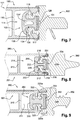
- the figure 1 annexed illustrates a door, designated as a whole by the reference 50, which equips a transport vehicle.
- This door comprises, in the usual manner, an opening formed by two leaves 60 and 70, and a frame 80 shown schematically, which is disposed at the periphery of a bay 90 formed in the box of this vehicle.
- This door can be provided with two leaves as in the illustrated example, but also with a single leaf.
- the door equips a train of the subway type.
- the invention finds application to doors intended to equip other transport vehicles such as including trams, trolleybuses, or trains different from that mentioned above.
- the leaves are vertical, in particular with reference to the figure 1 .
- the terms "inside” and “outside” are used with reference to the body of this transport vehicle.
- Each leaf 60, 70 comprises, in known manner, a central body 62, 72 equipped in particular with a window 63, 73 and an operating member 64, 74, for example of the push button type.
- This body is typically formed of two opposite facing respectively inner and outer, and a core interposed between these facings.
- a frame 66, 76 extends to the outer periphery of this body.
- This frame includes a profile, which is of known type, provided on the vertical edges of the body.
- this profile 1 comprises a core 10, and two wings 11 and 12 extending parallel to the main plane P60 of the leaf.
- This core 10 and these two wings 11 and 12 define a housing 14 substantially U-shaped, open opposite of this body.
- two ridges 16 and 17 protrude towards each other from a respective wing.
- these edges provide a hooking function of a seal.
- each wing is covered, at least in part, by a respective sheet 18 and 19, forming the inner and outer walls of the leaf.
- a so-called longitudinal direction X1-X1 is defined, with reference to the main direction of the joint, and a transverse direction Y1-Y1, with reference to this main direction.
- the directions X1-X1 and Y1-Y1 are respectively generally vertical and generally horizontal.
- the seal 2 is made of any suitable material, allowing it to perform its main functions, namely its attachment to the section 1, the return of the light emitted by the diodes, the watertightness and the detection of obstacles. In a constructive manner, a translucent seal, made in particular of silicone, will typically be used. Alternatively, other materials may be selected, such as soft PVC, Thermoplastic Elastomer (TPE), polyurethane, or any other suitable material.
- This seal 2 firstly comprises a solid base 20 intended to project outside the housing 14, so as to constitute a lighting region of the joint.
- This base is extended by an attachment region 21, intended to be housed in the interior volume of the aforementioned housing.
- this attachment region is an elastic snap region.
- This region 21 comprises two L-shaped lugs 22 and 23 which comprise mutually parallel intermediate branches 22 'and 23', and end branches 22 "and 23" projecting towards each other. These are extended by ribs 24 and 25 protruding opposite to each other.
- the base 20 and the attachment region 21 delimits an intermediate volume 28, bordered by walls 20 'and 21' respectively belonging to this base 20 and this attachment region 21.
- This intermediate volume which is intended for receiving of the key 3, is open opposite the base 20 so as to form a deformation space 29.
- the seal 2 extends over at least a substantial part of the height of the leaf and, preferably, on substantially all this height.
- the intermediate volume 28 opens at least at one longitudinal end of the seal, in particular at its upper end. Preferably, this volume 28 occupies the entire seal, so that it opens at both longitudinal ends of the latter.
- the key 3 comprises first a foot 30, intended to be received in the volume 28.
- This foot is provided with two lugs 31 and 32, cooperating with the opposite faces of the two legs 22 and 23.
- This foot is extended by a rod 34, extending inside the deformation space 29 along the main plane P60.
- This stem is terminated by a head curved 35, whose concavity is turned towards the foot 30.
- the head 35 has a peripheral periphery 36, able to bear against the edges of the profile.
- This key 3 is made of a material that gives it sufficient mechanical strength to block the seal 2, against efforts to extract the latter out of the housing 14 of the profile 1.
- the material of the key is also adapted , to enable the latter to provide a support function for the lighting member which will be described below.
- a key made of a plastic material which can be adapted to all types of leaves, in particular curved leaves.
- This key can also be made of a material providing an additional function of heat dissipation of the heat, generated in use by the lighting member.
- a wrench made of aluminum or a similar material. Note however that this type of material is less suitable than a plastic material, for curved leaves.
- the key 3 extends over at least a substantial part of the height of the seal 2 and, preferably, over substantially this entire height. Nevertheless, it is necessary to prevent this key 3 protrudes longitudinally with respect to the seal 2, once the signaling assembly according to the invention mounted on the leaf 60. Indeed such a longitudinal extension of the key would be likely to interfere with the functioning of the leaf.
- one or more immobilization means may be used, alone or in combination.
- these immobilizing means are removable or reversible means, namely that they can be disassembled without risk of damaging the key or seal.
- this axis can in particular be a pin or a screw.
- a screw, not shown, connecting the seal to the key this screw can for example be self-tapping in the material of the key.
- the lighting member 4 firstly comprises an elongated body 40 forming a support.
- This body is made of a material which gives it sufficient mechanical strength, so that it can be fixed against the key.
- this body is formed by a PCB (Printed Circuit Board, or Circuit Printed), of a type known per se.
- This body 40 is equipped with a plurality of lighting elements, which are light-emitting diodes 42 in the illustrated example.
- the number of these diodes, which are of known type per se, is for example between 20 and 600.
- These diodes are controlled in a conventional manner, by means of control means not shown, of a type known per se.
- the diodes 42 are arranged in the vicinity of the lighting region 20, being turned towards the facing wall 20 'belonging to the latter.
- the lighting member 4 extends over at least a substantial part of the height of the key 3 and, preferably, over substantially this entire height.
- This member 4 is mounted on the key 3 by means of fixing means, which can be used alone or in combination.
- two orifices 44 are provided at the opposite ends of the body 40, so as to allow this body to be screwed onto the foot 30 of the key 3.
- the body 40 it is also possible for the body 40 to be glued against the face opposite this foot 30.
- the figure 6 illustrates a further variant, wherein the foot 30 is extended by two flanges 38, which define a slide 39.
- the latter allows longitudinal insertion of the lighting member 4, while ensuring its retention in a transverse direction
- the seal 2 can be introduced into the profile 1 in a longitudinal direction, ie parallel to that X1-X1 of the figure 1 . Nevertheless, this solution is not preferred because it does not offer a satisfactory mounting convenience.
- the joint 2 is first displaced in the direction of the profile, according to the arrow F2 corresponding to a transverse direction parallel to the direction Y1-Y1 of the figure 1 .
- the seal 2 is secured to the section 1 in the substantially definitive position that it must adopt, is introduced into the inner volume 28 of the seal, the locking key 3 and the lighting member 4 which is mounted on it.
- This introduction is typically carried out longitudinally, namely in the direction X1-X1 of the figure 1 .
- the key 3 is in the desired position, it is immobilized advantageously relative to the seal, thanks to the immobilization means described above.
- the functional configuration of the signaling assembly is illustrated on the figure 4 .
- the latter shows that the different diodes 42 are placed closer to the light region of the seal, which gives great visibility to the information issued to travelers.
- this light region 20 and the profile 1 are represented on the figure 1 , just as the light region 20a and the profile 1 'associated with the other leaf 70.
- the presence of the key 3 further confers on the seal 2 a high resistance, with respect to tearing in the transverse direction Y1-Y1.
- the periphery 36 of the head of the key 3 bears directly against the edges 16 and 17, so as to oppose such tearing.
- the walls facing the foot 30 and the inner volume 28 of the seal delimit areas of mutual contact of large area, which provide additional resistance against such tearing.
- the figure 7 illustrates a first variant of the signaling assembly, according to the invention.
- mechanical elements similar to those of Figures 2 to 4 are assigned the same reference numbers, increased by 100.
- the signaling set of this figure 7 differs essentially from that of Figures 2 to 4 , in that the rod 134 of the key 103 is hollowed with a central recess 134 '. This makes it possible to maintain a thickness that is approximately constant, to avoid sink problems.
- this key is of massive shape, which is an advantage for heat dissipation, if this key is made of a material such as aluminum.
- the figure 8 illustrates a second variant of the signaling assembly, according to the invention.
- the signaling set of this figure 8 differs essentially from that of Figures 2 to 4 , in that the tabs 222 and 223 are devoid of ribs, such as those 24 and 25 of the first embodiment. Under these conditions, the attachment portion is not snapped on the edges 216 and 217, but simply adjusted by wedging between them.
- the attachment of the seal is provided by the key 203, in particular its lugs 231 and 232 and its head 235 which covers the aforementioned lugs 222 and 223, while abutting against the edges 216 and 217. This embodiment is particularly well adapted to reduced congestion.
- the figure 9 illustrates a third variant of the signaling assembly, according to the invention.
- mechanical elements similar to those of Figures 2 to 4 are assigned the same reference numbers, increased by 300.
- the signaling set of this figure 9 differs essentially from that of Figures 2 to 4 , in that the leaf 360 has a lower thickness, typically close to 25 millimeters.
- the light region 320 is extended by two tabs 320a and 320b, which cover the free edges of the profile 301 opposite tabs 322 and 323.
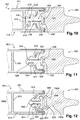
- the figure 10 illustrates a fourth variant of the signaling assembly, according to the invention.
- the signaling set of this figure 10 differs essentially from that of Figures 2 to 4 , in that the web 410 of the profile 401 is provided with a cover 410 ', delimiting a space 414' or secondary housing.
- the latter communicates with the main housing 414 through a hole 410 "of the cover, through which the rod 434 of the key 403 enters, so that the head 435 of the key can be received in the secondary space 414 '.
- the tensile stress experienced by the seal the head 435 of the key 403 abuts against the inner faces facing the cover 410 ', so that the key is opposed to the tearing of this seal.
- the figure 11 illustrates a fifth variant of the signaling assembly, according to the invention.
- mechanical elements similar to those of Figures 2 to 4 are assigned the same reference numbers, increased by 500.
- the signaling set of this figure 11 differs essentially from that of the previous figures, in that the intermediate volume 528 of the seal 502 is closed in transverse view. Under these conditions, the key 503 is entirely housed in this volume 528, without protruding outside the latter. Moreover, this key is devoid of head. In contrast the free end 534 'of its rod 534 is flared so as to avoid any collapse of the seal 502, at its region in contact with the edges 516 and 517.
- the figure 12 illustrates a sixth variant of the signaling assembly, according to the invention.
- mechanical elements similar to those of Figures 2 to 4 are assigned the same reference numbers, increased by 600.
- key 503 of the embodiment of the figure 11 key 603 of this embodiment is headless.
- the free end 634 'of the rod 634 is flared so as to avoid any collapse of the seal 602, at its region in contact with the edges 616 and 617.
- the intermediate volume 628 of the seal 602 is open in transverse view, so that this free end protrudes slightly outside this volume 628.
- this wall 620 'of the base 620, bordering the intermediate volume 628, is curved.
- the distance between this wall and the lighting elements 642 decreases, from the median region of this wall towards its lateral zones.
- this wall 620 ' may have any shape equivalent to a curved shape, in particular an arched shape as in the figure 9 or a peak form.
- the signaling assembly according to the invention, has many advantages over the prior art.
- the invention makes it possible to generate a luminous intensity, in the region of the joint to be illuminated, which is much higher than in the known solutions.
- this light intensity guarantees a satisfactory perception for the users, even when the aforementioned joint is exposed to natural light, especially to the sun.
- the lighting means are housed in an interior space in the seal, closer to the light region of the latter. Consequently, the distance separating these lighting means and this light region is reduced.
- no mechanical element capable of interfering with the light emitted by the lighting means is interposed between these lighting means and this light region.
- the invention makes it easier to mount the lighting means, with regard to known solutions. Indeed, these lighting means can be fixed directly to the locking key, before the insertion of the latter in the interior volume of the seal.
- the invention thus makes it possible to overcome possible accessibility problems related to lighting means which would be mounted at the bottom of the housing of the profile. Note that, according to the invention, this accessibility is not impacted in the case where the aforementioned housing receives equipment necessary for the proper functioning of the leaf, such as cables or a linkage.
- the prior fixing of these lighting means on the key also reduces the risk of damage during assembly.
- the invention guarantees maintenance of the lighting means which is particularly convenient. Indeed, according to the invention, the lighting means can be changed by a simple extraction of the locking key, in a longitudinal direction. Therefore, the invention does not require to separate the entire seal, out of the housing profile.
- the invention allows easy assembly of the seal in its housing, while ensuring a reliable in place.
- the attachment of the seal on the profile can be achieved without significant physical effort on the part of the operator.
- the presence of the locking key allows safe mounting, in particular against a transverse extraction of this seal.
- the presence of the head 36, forming a so-called abutment region of the key, is particularly advantageous. Indeed, it offers a particularly reliable resistance against the pulling efforts of the seal.
- the invention is also applicable to a sealing assembly, which is devoid of lighting means, which assembly comprises a seal and a locking key incorporating such a stop region.
- the lighting member is integrated in the overall volume, formed by the leaf and the seal associated therewith.
- this volume is bordered by the wings 11 and 12 of the profile 1, as well as by the inner and outer faces respectively of the base 20.
- this lighting member does not protrude laterally, with respect to edges of this leaf and this joint. This protects the lighting member against shocks, exerted along an axis perpendicular to the main plane of the leaf.
- WO 2011/138292 is not satisfactory on this aspect, since it provides to place this luminaire body applied to the leaf.
Landscapes
- Engineering & Computer Science (AREA)
- Mechanical Engineering (AREA)
- Lighting Device Outwards From Vehicle And Optical Signal (AREA)
- Lock And Its Accessories (AREA)
- Arrangements Of Lighting Devices For Vehicle Interiors, Mounting And Supporting Thereof, Circuits Therefore (AREA)
- Seal Device For Vehicle (AREA)
- Arrangement Of Elements, Cooling, Sealing, Or The Like Of Lighting Devices (AREA)
Applications Claiming Priority (1)
| Application Number | Priority Date | Filing Date | Title |
|---|---|---|---|
| FR1851501A FR3078034B1 (fr) | 2018-02-22 | 2018-02-22 | Ensemble de signalisation pour vantail, porte et vehicule de transport correspondants |
Publications (2)
| Publication Number | Publication Date |
|---|---|
| EP3530508A1 true EP3530508A1 (de) | 2019-08-28 |
| EP3530508B1 EP3530508B1 (de) | 2020-10-14 |
Family
ID=62143363
Family Applications (1)
| Application Number | Title | Priority Date | Filing Date |
|---|---|---|---|
| EP19156580.3A Active EP3530508B1 (de) | 2018-02-22 | 2019-02-12 | Signalisierungseinheit für flügel, entsprechende tür und entsprechendes transportfahrzeug |
Country Status (5)
| Country | Link |
|---|---|
| US (1) | US10814708B2 (de) |
| EP (1) | EP3530508B1 (de) |
| CN (1) | CN110182235B (de) |
| ES (1) | ES2834928T3 (de) |
| FR (1) | FR3078034B1 (de) |
Families Citing this family (13)
| Publication number | Priority date | Publication date | Assignee | Title |
|---|---|---|---|---|
| DE102017112133A1 (de) * | 2017-06-01 | 2018-12-06 | Gummi-Welz Gmbh U. Co. Kg Gummi-Kunststofftechnik-Schaumstoffe | Sicherheitsprofilleiste und Tür mit Sicherheitsprofilleiste |
| CN111094686B (zh) * | 2017-09-19 | 2022-01-25 | 克诺尔有限公司 | 用于车辆门的防夹的装置、用于车辆的门系统和用于制造用于车辆门的防夹的装置的方法 |
| US10919631B2 (en) * | 2018-10-29 | 2021-02-16 | Safran Cabin Inc. | Aircraft with multiple doors and multiple zones |
| US11034452B2 (en) * | 2018-10-29 | 2021-06-15 | Safran Cabin Inc. | Aircraft with staggered seating arrangement |
| US10661879B2 (en) * | 2018-10-29 | 2020-05-26 | Safran Cabin Inc. | Aircraft with selective cargo area access |
| JP6858740B2 (ja) * | 2018-11-29 | 2021-04-14 | 西川ゴム工業株式会社 | ウェザーストリップ、ウェザーストリップの取付構造、およびウェザーストリップの取付方法 |
| US11383739B2 (en) * | 2018-12-27 | 2022-07-12 | Westinghouse Air Brake Technologies Corporation | Seal retention device |
| DE202019106056U1 (de) * | 2019-10-31 | 2021-02-03 | Gebr. Bode Gmbh & Co. Kg | Türflügel mit Leuchtprofil |
| DE102020004412A1 (de) * | 2020-07-22 | 2022-01-27 | Knorr-Bremse Gesellschaft Mit Beschränkter Haftung | Lichtleisteneinrichtung für einen Türflügel eines Einstiegssystems eines Schienenfahrzeugs |
| KR20220136793A (ko) * | 2021-04-01 | 2022-10-11 | 현대자동차주식회사 | 차량용 밀봉구조 |
| EP4219204B1 (de) * | 2022-01-28 | 2025-08-20 | Gummi-Welz GmbH u. Co. KG Gummi-Kunststofftechnik-Schaumstoffe | Innenschwenktür mit abdichtprofil und fahrzeug mit der innenschwenktür |
| DE202022103749U1 (de) * | 2022-07-05 | 2022-07-19 | Knaus Tabbert Ag | Abdeckprofil |
| FR3147752B1 (fr) * | 2023-04-13 | 2025-12-12 | Faiveley Transp Tours | Ensemble de signalisation d’informations dirigees vers les cotes interieur et exterieur d’un vantail, porte et vehicule de transport correspondants |
Citations (6)
| Publication number | Priority date | Publication date | Assignee | Title |
|---|---|---|---|---|
| DE1982028U (de) * | 1967-12-20 | 1968-03-28 | Kiekert Soehne Arn | Fingerschutzleiste fuer tueren. |
| US4051336A (en) * | 1976-04-29 | 1977-09-27 | Miller Brothers | Pressure sensitive door edge switch and actuator construction |
| DE102015112041A1 (de) * | 2015-07-23 | 2017-01-26 | Novoferm Gmbh | Tor, insbesondere Garagentor |
| EP3186126A1 (de) * | 2014-08-28 | 2017-07-05 | Faiveley Transport Tours | Dichtungssystem für öffnungsfähiges paneel mit einem profilelement zur aufnahme einer dichtung, die durch eine gleitfeder fixiert ist |
| EP3409557A1 (de) * | 2017-06-01 | 2018-12-05 | JC Disseny Ingenieria i Aplicacions S.L. | Dichtungsstreifen für fahrzeugtüren |
| WO2018219694A1 (de) * | 2017-06-01 | 2018-12-06 | Gummi-Welz Gmbh & Co. Kg Gummi-Kunststofftechnik-Schaumstoffe | Sicherheitsprofilleiste und tür mit sicherheitsprofilleiste |
Family Cites Families (6)
| Publication number | Priority date | Publication date | Assignee | Title |
|---|---|---|---|---|
| DE2658660C2 (de) * | 1976-12-23 | 1984-07-12 | Erwin Sick Gmbh Optik-Elektronik, 7808 Waldkirch | Sicherheitsvorrichtung an einer automatisch schließenden Schiebetür |
| US5433031A (en) * | 1994-04-06 | 1995-07-18 | Mark Iv Transportation Products Corporation | Resilient edges for power operated doors |
| US20020152686A1 (en) * | 2001-04-18 | 2002-10-24 | William Whitehead | Illuminating weatherseal |
| US7226112B2 (en) * | 2003-10-02 | 2007-06-05 | Nicholas Plastics Incorporated | Pinch warning and illumination system |
| DE102010019764B4 (de) * | 2010-05-07 | 2013-09-19 | Knorr-Bremse Gmbh | Leuchtfähige Fingerschutzvorrichtung für eine Tür eines Fahrzeugs |
| FR3035182B1 (fr) * | 2015-04-16 | 2018-06-15 | Valeo Vision | Dispositif lumineux pour l'eclairage et/ou la signalisation d'un vehicule automobile |
-
2018
- 2018-02-22 FR FR1851501A patent/FR3078034B1/fr not_active Expired - Fee Related
-
2019
- 2019-02-11 US US16/272,218 patent/US10814708B2/en active Active
- 2019-02-12 EP EP19156580.3A patent/EP3530508B1/de active Active
- 2019-02-12 ES ES19156580T patent/ES2834928T3/es active Active
- 2019-02-21 CN CN201910128837.7A patent/CN110182235B/zh active Active
Patent Citations (6)
| Publication number | Priority date | Publication date | Assignee | Title |
|---|---|---|---|---|
| DE1982028U (de) * | 1967-12-20 | 1968-03-28 | Kiekert Soehne Arn | Fingerschutzleiste fuer tueren. |
| US4051336A (en) * | 1976-04-29 | 1977-09-27 | Miller Brothers | Pressure sensitive door edge switch and actuator construction |
| EP3186126A1 (de) * | 2014-08-28 | 2017-07-05 | Faiveley Transport Tours | Dichtungssystem für öffnungsfähiges paneel mit einem profilelement zur aufnahme einer dichtung, die durch eine gleitfeder fixiert ist |
| DE102015112041A1 (de) * | 2015-07-23 | 2017-01-26 | Novoferm Gmbh | Tor, insbesondere Garagentor |
| EP3409557A1 (de) * | 2017-06-01 | 2018-12-05 | JC Disseny Ingenieria i Aplicacions S.L. | Dichtungsstreifen für fahrzeugtüren |
| WO2018219694A1 (de) * | 2017-06-01 | 2018-12-06 | Gummi-Welz Gmbh & Co. Kg Gummi-Kunststofftechnik-Schaumstoffe | Sicherheitsprofilleiste und tür mit sicherheitsprofilleiste |
Also Published As
| Publication number | Publication date |
|---|---|
| CN110182235B (zh) | 2023-03-28 |
| FR3078034B1 (fr) | 2020-02-14 |
| ES2834928T3 (es) | 2021-06-21 |
| US20190255923A1 (en) | 2019-08-22 |
| EP3530508B1 (de) | 2020-10-14 |
| US10814708B2 (en) | 2020-10-27 |
| FR3078034A1 (fr) | 2019-08-23 |
| CN110182235A (zh) | 2019-08-30 |
Similar Documents
| Publication | Publication Date | Title |
|---|---|---|
| EP3530508B1 (de) | Signalisierungseinheit für flügel, entsprechende tür und entsprechendes transportfahrzeug | |
| FR2780927A1 (fr) | Dispositif de fixation des crosses d'un pare-chocs sur une aile de carrosserie de vehicule | |
| EP2882056B1 (de) | Rahmen für Einbaumontage einer Elektrodose in einer Wand und Montage eines solchen Rahmens mit einer Elektrodose . | |
| EP3335957B1 (de) | Schwenktür mit integrierter erhöhter schwelle | |
| EP3802181B1 (de) | Signalanordnung für ein türblatt und entsprechende tür und transportfahrzeug | |
| EP3186126B1 (de) | Dichtungssystem für öffnungsfähiges paneel mit einem profilelement zur aufnahme einer dichtung, die durch eine gleitfeder fixiert ist | |
| EP0479697A1 (de) | Im Boden liegende Anzeige-, Dekorations-, Werbe- oder Sicherheitsvorrichtung | |
| EP1051573B1 (de) | Verfahren zum befestigen irgendeines gegenstandes an irgendeinem träger und zubehör zur durchführung von diesem verfahren | |
| CA3119141A1 (fr) | Dispositif de largage d'un panneau d'aeronef et aeronef associe | |
| EP3564075A1 (de) | Stossfänger mit integrierter markierungszelle | |
| FR2830555A1 (fr) | Nez de marche lumineux | |
| EP4446191A1 (de) | Informationssignalisierungsanordnung für die innen- und aussenseite eines flügels, entsprechende tür und transportfahrzeug | |
| EP3069936B1 (de) | Vorrichtung, die eine trittstufe eines kraftfahrzeugs bildet | |
| WO2017006014A1 (fr) | Élément de dispositif d'éclairage limitant la rétention d'eau a proximité d'un joint d'étanchéité | |
| FR2928317A1 (fr) | Dispositif de galerie interieure pour vehicule automobile, et vehicule automobile correspondant. | |
| BE1018427A3 (fr) | Marches rectangulaires pleines et escalier realise avec de telles marches. | |
| EP3919325B1 (de) | Platte für die montage einer lichtquelle an einer fahrzeugwand, und fahrzeug, insbesondere schienenfahrzeug, das eine solche montageplatte umfasst | |
| FR2713170A1 (fr) | Porte-plaque minéralogique pour véhicule automobile. | |
| EP3210821B1 (de) | Endstück für profil, das einen querschnittsabschnitt in u-form umfasst | |
| FR2990621A1 (fr) | Plot podotactile comportant un piece de base et un opercule | |
| FR3018588A1 (fr) | Module lumineux comportant plusieurs sources lumineuses surfaciques | |
| FR2715681A1 (fr) | Dispositif de protection d'une structure du type marche, à l'aide d'un joint souple tubulaire. | |
| FR2794698A1 (fr) | Piece de garnissage pour marche d'acces a l'habitacle d'un vehicule automobile | |
| FR2951671A1 (fr) | Dispositif d'etancheite pour un montant de cadre de porte de vehicule | |
| FR2548110A1 (fr) | Transport des skis sur le toit d'une automobile |
Legal Events
| Date | Code | Title | Description |
|---|---|---|---|
| PUAI | Public reference made under article 153(3) epc to a published international application that has entered the european phase |
Free format text: ORIGINAL CODE: 0009012 |
|
| STAA | Information on the status of an ep patent application or granted ep patent |
Free format text: STATUS: THE APPLICATION HAS BEEN PUBLISHED |
|
| AK | Designated contracting states |
Kind code of ref document: A1 Designated state(s): AL AT BE BG CH CY CZ DE DK EE ES FI FR GB GR HR HU IE IS IT LI LT LU LV MC MK MT NL NO PL PT RO RS SE SI SK SM TR |
|
| AX | Request for extension of the european patent |
Extension state: BA ME |
|
| STAA | Information on the status of an ep patent application or granted ep patent |
Free format text: STATUS: REQUEST FOR EXAMINATION WAS MADE |
|
| 17P | Request for examination filed |
Effective date: 20200228 |
|
| RBV | Designated contracting states (corrected) |
Designated state(s): AL AT BE BG CH CY CZ DE DK EE ES FI FR GB GR HR HU IE IS IT LI LT LU LV MC MK MT NL NO PL PT RO RS SE SI SK SM TR |
|
| GRAP | Despatch of communication of intention to grant a patent |
Free format text: ORIGINAL CODE: EPIDOSNIGR1 |
|
| STAA | Information on the status of an ep patent application or granted ep patent |
Free format text: STATUS: GRANT OF PATENT IS INTENDED |
|
| RIC1 | Information provided on ipc code assigned before grant |
Ipc: B60J 10/86 20160101ALI20200615BHEP Ipc: B60J 10/36 20160101ALI20200615BHEP Ipc: B60J 10/00 20160101AFI20200615BHEP Ipc: B61D 19/02 20060101ALI20200615BHEP Ipc: B61D 29/00 20060101ALI20200615BHEP Ipc: B60Q 1/32 20060101ALI20200615BHEP |
|
| INTG | Intention to grant announced |
Effective date: 20200715 |
|
| GRAS | Grant fee paid |
Free format text: ORIGINAL CODE: EPIDOSNIGR3 |
|
| GRAA | (expected) grant |
Free format text: ORIGINAL CODE: 0009210 |
|
| STAA | Information on the status of an ep patent application or granted ep patent |
Free format text: STATUS: THE PATENT HAS BEEN GRANTED |
|
| AK | Designated contracting states |
Kind code of ref document: B1 Designated state(s): AL AT BE BG CH CY CZ DE DK EE ES FI FR GB GR HR HU IE IS IT LI LT LU LV MC MK MT NL NO PL PT RO RS SE SI SK SM TR |
|
| REG | Reference to a national code |
Ref country code: GB Ref legal event code: FG4D Free format text: NOT ENGLISH |
|
| REG | Reference to a national code |
Ref country code: AT Ref legal event code: REF Ref document number: 1323228 Country of ref document: AT Kind code of ref document: T Effective date: 20201015 Ref country code: CH Ref legal event code: EP |
|
| REG | Reference to a national code |
Ref country code: DE Ref legal event code: R096 Ref document number: 602019000911 Country of ref document: DE |
|
| REG | Reference to a national code |
Ref country code: IE Ref legal event code: FG4D Free format text: LANGUAGE OF EP DOCUMENT: FRENCH |
|
| REG | Reference to a national code |
Ref country code: AT Ref legal event code: MK05 Ref document number: 1323228 Country of ref document: AT Kind code of ref document: T Effective date: 20201014 |
|
| REG | Reference to a national code |
Ref country code: NL Ref legal event code: MP Effective date: 20201014 |
|
| PG25 | Lapsed in a contracting state [announced via postgrant information from national office to epo] |
Ref country code: PT Free format text: LAPSE BECAUSE OF FAILURE TO SUBMIT A TRANSLATION OF THE DESCRIPTION OR TO PAY THE FEE WITHIN THE PRESCRIBED TIME-LIMIT Effective date: 20210215 Ref country code: RS Free format text: LAPSE BECAUSE OF FAILURE TO SUBMIT A TRANSLATION OF THE DESCRIPTION OR TO PAY THE FEE WITHIN THE PRESCRIBED TIME-LIMIT Effective date: 20201014 Ref country code: FI Free format text: LAPSE BECAUSE OF FAILURE TO SUBMIT A TRANSLATION OF THE DESCRIPTION OR TO PAY THE FEE WITHIN THE PRESCRIBED TIME-LIMIT Effective date: 20201014 Ref country code: NO Free format text: LAPSE BECAUSE OF FAILURE TO SUBMIT A TRANSLATION OF THE DESCRIPTION OR TO PAY THE FEE WITHIN THE PRESCRIBED TIME-LIMIT Effective date: 20210114 Ref country code: GR Free format text: LAPSE BECAUSE OF FAILURE TO SUBMIT A TRANSLATION OF THE DESCRIPTION OR TO PAY THE FEE WITHIN THE PRESCRIBED TIME-LIMIT Effective date: 20210115 |
|
| REG | Reference to a national code |
Ref country code: LT Ref legal event code: MG4D |
|
| PG25 | Lapsed in a contracting state [announced via postgrant information from national office to epo] |
Ref country code: BG Free format text: LAPSE BECAUSE OF FAILURE TO SUBMIT A TRANSLATION OF THE DESCRIPTION OR TO PAY THE FEE WITHIN THE PRESCRIBED TIME-LIMIT Effective date: 20210114 Ref country code: SE Free format text: LAPSE BECAUSE OF FAILURE TO SUBMIT A TRANSLATION OF THE DESCRIPTION OR TO PAY THE FEE WITHIN THE PRESCRIBED TIME-LIMIT Effective date: 20201014 Ref country code: LV Free format text: LAPSE BECAUSE OF FAILURE TO SUBMIT A TRANSLATION OF THE DESCRIPTION OR TO PAY THE FEE WITHIN THE PRESCRIBED TIME-LIMIT Effective date: 20201014 Ref country code: IS Free format text: LAPSE BECAUSE OF FAILURE TO SUBMIT A TRANSLATION OF THE DESCRIPTION OR TO PAY THE FEE WITHIN THE PRESCRIBED TIME-LIMIT Effective date: 20210214 Ref country code: PL Free format text: LAPSE BECAUSE OF FAILURE TO SUBMIT A TRANSLATION OF THE DESCRIPTION OR TO PAY THE FEE WITHIN THE PRESCRIBED TIME-LIMIT Effective date: 20201014 Ref country code: AT Free format text: LAPSE BECAUSE OF FAILURE TO SUBMIT A TRANSLATION OF THE DESCRIPTION OR TO PAY THE FEE WITHIN THE PRESCRIBED TIME-LIMIT Effective date: 20201014 |
|
| REG | Reference to a national code |
Ref country code: ES Ref legal event code: FG2A Ref document number: 2834928 Country of ref document: ES Kind code of ref document: T3 Effective date: 20210621 |
|
| PG25 | Lapsed in a contracting state [announced via postgrant information from national office to epo] |
Ref country code: NL Free format text: LAPSE BECAUSE OF FAILURE TO SUBMIT A TRANSLATION OF THE DESCRIPTION OR TO PAY THE FEE WITHIN THE PRESCRIBED TIME-LIMIT Effective date: 20201014 Ref country code: HR Free format text: LAPSE BECAUSE OF FAILURE TO SUBMIT A TRANSLATION OF THE DESCRIPTION OR TO PAY THE FEE WITHIN THE PRESCRIBED TIME-LIMIT Effective date: 20201014 |
|
| REG | Reference to a national code |
Ref country code: DE Ref legal event code: R097 Ref document number: 602019000911 Country of ref document: DE |
|
| PG25 | Lapsed in a contracting state [announced via postgrant information from national office to epo] |
Ref country code: SK Free format text: LAPSE BECAUSE OF FAILURE TO SUBMIT A TRANSLATION OF THE DESCRIPTION OR TO PAY THE FEE WITHIN THE PRESCRIBED TIME-LIMIT Effective date: 20201014 Ref country code: SM Free format text: LAPSE BECAUSE OF FAILURE TO SUBMIT A TRANSLATION OF THE DESCRIPTION OR TO PAY THE FEE WITHIN THE PRESCRIBED TIME-LIMIT Effective date: 20201014 Ref country code: EE Free format text: LAPSE BECAUSE OF FAILURE TO SUBMIT A TRANSLATION OF THE DESCRIPTION OR TO PAY THE FEE WITHIN THE PRESCRIBED TIME-LIMIT Effective date: 20201014 Ref country code: RO Free format text: LAPSE BECAUSE OF FAILURE TO SUBMIT A TRANSLATION OF THE DESCRIPTION OR TO PAY THE FEE WITHIN THE PRESCRIBED TIME-LIMIT Effective date: 20201014 Ref country code: LT Free format text: LAPSE BECAUSE OF FAILURE TO SUBMIT A TRANSLATION OF THE DESCRIPTION OR TO PAY THE FEE WITHIN THE PRESCRIBED TIME-LIMIT Effective date: 20201014 |
|
| PLBE | No opposition filed within time limit |
Free format text: ORIGINAL CODE: 0009261 |
|
| STAA | Information on the status of an ep patent application or granted ep patent |
Free format text: STATUS: NO OPPOSITION FILED WITHIN TIME LIMIT |
|
| PG25 | Lapsed in a contracting state [announced via postgrant information from national office to epo] |
Ref country code: DK Free format text: LAPSE BECAUSE OF FAILURE TO SUBMIT A TRANSLATION OF THE DESCRIPTION OR TO PAY THE FEE WITHIN THE PRESCRIBED TIME-LIMIT Effective date: 20201014 |
|
| 26N | No opposition filed |
Effective date: 20210715 |
|
| PG25 | Lapsed in a contracting state [announced via postgrant information from national office to epo] |
Ref country code: MC Free format text: LAPSE BECAUSE OF FAILURE TO SUBMIT A TRANSLATION OF THE DESCRIPTION OR TO PAY THE FEE WITHIN THE PRESCRIBED TIME-LIMIT Effective date: 20201014 |
|
| REG | Reference to a national code |
Ref country code: BE Ref legal event code: MM Effective date: 20210228 |
|
| PG25 | Lapsed in a contracting state [announced via postgrant information from national office to epo] |
Ref country code: AL Free format text: LAPSE BECAUSE OF FAILURE TO SUBMIT A TRANSLATION OF THE DESCRIPTION OR TO PAY THE FEE WITHIN THE PRESCRIBED TIME-LIMIT Effective date: 20201014 Ref country code: IT Free format text: LAPSE BECAUSE OF FAILURE TO SUBMIT A TRANSLATION OF THE DESCRIPTION OR TO PAY THE FEE WITHIN THE PRESCRIBED TIME-LIMIT Effective date: 20201014 Ref country code: LU Free format text: LAPSE BECAUSE OF NON-PAYMENT OF DUE FEES Effective date: 20210212 |
|
| PG25 | Lapsed in a contracting state [announced via postgrant information from national office to epo] |
Ref country code: SI Free format text: LAPSE BECAUSE OF FAILURE TO SUBMIT A TRANSLATION OF THE DESCRIPTION OR TO PAY THE FEE WITHIN THE PRESCRIBED TIME-LIMIT Effective date: 20201014 |
|
| PG25 | Lapsed in a contracting state [announced via postgrant information from national office to epo] |
Ref country code: IE Free format text: LAPSE BECAUSE OF NON-PAYMENT OF DUE FEES Effective date: 20210212 |
|
| PG25 | Lapsed in a contracting state [announced via postgrant information from national office to epo] |
Ref country code: IS Free format text: LAPSE BECAUSE OF FAILURE TO SUBMIT A TRANSLATION OF THE DESCRIPTION OR TO PAY THE FEE WITHIN THE PRESCRIBED TIME-LIMIT Effective date: 20210214 |
|
| PG25 | Lapsed in a contracting state [announced via postgrant information from national office to epo] |
Ref country code: BE Free format text: LAPSE BECAUSE OF NON-PAYMENT OF DUE FEES Effective date: 20210228 |
|
| REG | Reference to a national code |
Ref country code: CH Ref legal event code: PL |
|
| PG25 | Lapsed in a contracting state [announced via postgrant information from national office to epo] |
Ref country code: LI Free format text: LAPSE BECAUSE OF NON-PAYMENT OF DUE FEES Effective date: 20220228 Ref country code: CH Free format text: LAPSE BECAUSE OF NON-PAYMENT OF DUE FEES Effective date: 20220228 |
|
| P01 | Opt-out of the competence of the unified patent court (upc) registered |
Effective date: 20230403 |
|
| P02 | Opt-out of the competence of the unified patent court (upc) changed |
Effective date: 20230524 |
|
| PG25 | Lapsed in a contracting state [announced via postgrant information from national office to epo] |
Ref country code: CY Free format text: LAPSE BECAUSE OF FAILURE TO SUBMIT A TRANSLATION OF THE DESCRIPTION OR TO PAY THE FEE WITHIN THE PRESCRIBED TIME-LIMIT Effective date: 20201014 |
|
| PG25 | Lapsed in a contracting state [announced via postgrant information from national office to epo] |
Ref country code: HU Free format text: LAPSE BECAUSE OF FAILURE TO SUBMIT A TRANSLATION OF THE DESCRIPTION OR TO PAY THE FEE WITHIN THE PRESCRIBED TIME-LIMIT; INVALID AB INITIO Effective date: 20190212 |
|
| PG25 | Lapsed in a contracting state [announced via postgrant information from national office to epo] |
Ref country code: MK Free format text: LAPSE BECAUSE OF FAILURE TO SUBMIT A TRANSLATION OF THE DESCRIPTION OR TO PAY THE FEE WITHIN THE PRESCRIBED TIME-LIMIT Effective date: 20201014 |
|
| PGFP | Annual fee paid to national office [announced via postgrant information from national office to epo] |
Ref country code: DE Payment date: 20240227 Year of fee payment: 6 Ref country code: GB Payment date: 20240222 Year of fee payment: 6 |
|
| PGFP | Annual fee paid to national office [announced via postgrant information from national office to epo] |
Ref country code: FR Payment date: 20240227 Year of fee payment: 6 |
|
| PG25 | Lapsed in a contracting state [announced via postgrant information from national office to epo] |
Ref country code: TR Free format text: LAPSE BECAUSE OF FAILURE TO SUBMIT A TRANSLATION OF THE DESCRIPTION OR TO PAY THE FEE WITHIN THE PRESCRIBED TIME-LIMIT Effective date: 20201014 |
|
| PG25 | Lapsed in a contracting state [announced via postgrant information from national office to epo] |
Ref country code: MT Free format text: LAPSE BECAUSE OF FAILURE TO SUBMIT A TRANSLATION OF THE DESCRIPTION OR TO PAY THE FEE WITHIN THE PRESCRIBED TIME-LIMIT Effective date: 20201014 |
|
| PGFP | Annual fee paid to national office [announced via postgrant information from national office to epo] |
Ref country code: ES Payment date: 20250311 Year of fee payment: 7 |
|
| PGFP | Annual fee paid to national office [announced via postgrant information from national office to epo] |
Ref country code: CZ Payment date: 20250205 Year of fee payment: 7 |
|
| REG | Reference to a national code |
Ref country code: DE Ref legal event code: R119 Ref document number: 602019000911 Country of ref document: DE |
|
| GBPC | Gb: european patent ceased through non-payment of renewal fee |
Effective date: 20250212 |
|
| PG25 | Lapsed in a contracting state [announced via postgrant information from national office to epo] |
Ref country code: DE Free format text: LAPSE BECAUSE OF NON-PAYMENT OF DUE FEES Effective date: 20250902 |
|
| PG25 | Lapsed in a contracting state [announced via postgrant information from national office to epo] |
Ref country code: GB Free format text: LAPSE BECAUSE OF NON-PAYMENT OF DUE FEES Effective date: 20250212 |
|
| PG25 | Lapsed in a contracting state [announced via postgrant information from national office to epo] |
Ref country code: FR Free format text: LAPSE BECAUSE OF NON-PAYMENT OF DUE FEES Effective date: 20250228 |