EP3531099A1 - Appareil de diagnostic - Google Patents
Appareil de diagnostic Download PDFInfo
- Publication number
- EP3531099A1 EP3531099A1 EP18204357.0A EP18204357A EP3531099A1 EP 3531099 A1 EP3531099 A1 EP 3531099A1 EP 18204357 A EP18204357 A EP 18204357A EP 3531099 A1 EP3531099 A1 EP 3531099A1
- Authority
- EP
- European Patent Office
- Prior art keywords
- diagnosis
- fiber optic
- optic sensor
- processor
- self
- Prior art date
- Legal status (The legal status is an assumption and is not a legal conclusion. Google has not performed a legal analysis and makes no representation as to the accuracy of the status listed.)
- Granted
Links
Images


Classifications
-
- G—PHYSICS
- G01—MEASURING; TESTING
- G01M—TESTING STATIC OR DYNAMIC BALANCE OF MACHINES OR STRUCTURES; TESTING OF STRUCTURES OR APPARATUS, NOT OTHERWISE PROVIDED FOR
- G01M11/00—Testing of optical apparatus; Testing structures by optical methods not otherwise provided for
- G01M11/08—Testing mechanical properties
- G01M11/083—Testing mechanical properties by using an optical fiber in contact with the device under test [DUT]
-
- G—PHYSICS
- G01—MEASURING; TESTING
- G01B—MEASURING LENGTH, THICKNESS OR SIMILAR LINEAR DIMENSIONS; MEASURING ANGLES; MEASURING AREAS; MEASURING IRREGULARITIES OF SURFACES OR CONTOURS
- G01B11/00—Measuring arrangements characterised by the use of optical techniques
-
- G—PHYSICS
- G01—MEASURING; TESTING
- G01D—MEASURING NOT SPECIALLY ADAPTED FOR A SPECIFIC VARIABLE; ARRANGEMENTS FOR MEASURING TWO OR MORE VARIABLES NOT COVERED IN A SINGLE OTHER SUBCLASS; TARIFF METERING APPARATUS; MEASURING OR TESTING NOT OTHERWISE PROVIDED FOR
- G01D18/00—Testing or calibrating apparatus or arrangements provided for in groups G01D1/00 - G01D15/00
-
- G—PHYSICS
- G01—MEASURING; TESTING
- G01D—MEASURING NOT SPECIALLY ADAPTED FOR A SPECIFIC VARIABLE; ARRANGEMENTS FOR MEASURING TWO OR MORE VARIABLES NOT COVERED IN A SINGLE OTHER SUBCLASS; TARIFF METERING APPARATUS; MEASURING OR TESTING NOT OTHERWISE PROVIDED FOR
- G01D5/00—Mechanical means for transferring the output of a sensing member; Means for converting the output of a sensing member to another variable where the form or nature of the sensing member does not constrain the means for converting; Transducers not specially adapted for a specific variable
- G01D5/26—Mechanical means for transferring the output of a sensing member; Means for converting the output of a sensing member to another variable where the form or nature of the sensing member does not constrain the means for converting; Transducers not specially adapted for a specific variable characterised by optical transfer means, i.e. using infrared, visible, or ultraviolet light
- G01D5/32—Mechanical means for transferring the output of a sensing member; Means for converting the output of a sensing member to another variable where the form or nature of the sensing member does not constrain the means for converting; Transducers not specially adapted for a specific variable characterised by optical transfer means, i.e. using infrared, visible, or ultraviolet light with attenuation or whole or partial obturation of beams of light
- G01D5/34—Mechanical means for transferring the output of a sensing member; Means for converting the output of a sensing member to another variable where the form or nature of the sensing member does not constrain the means for converting; Transducers not specially adapted for a specific variable characterised by optical transfer means, i.e. using infrared, visible, or ultraviolet light with attenuation or whole or partial obturation of beams of light the beams of light being detected by photocells
- G01D5/353—Mechanical means for transferring the output of a sensing member; Means for converting the output of a sensing member to another variable where the form or nature of the sensing member does not constrain the means for converting; Transducers not specially adapted for a specific variable characterised by optical transfer means, i.e. using infrared, visible, or ultraviolet light with attenuation or whole or partial obturation of beams of light the beams of light being detected by photocells influencing the transmission properties of an optical fibre
- G01D5/35306—Mechanical means for transferring the output of a sensing member; Means for converting the output of a sensing member to another variable where the form or nature of the sensing member does not constrain the means for converting; Transducers not specially adapted for a specific variable characterised by optical transfer means, i.e. using infrared, visible, or ultraviolet light with attenuation or whole or partial obturation of beams of light the beams of light being detected by photocells influencing the transmission properties of an optical fibre using an interferometer arrangement
- G01D5/35309—Mechanical means for transferring the output of a sensing member; Means for converting the output of a sensing member to another variable where the form or nature of the sensing member does not constrain the means for converting; Transducers not specially adapted for a specific variable characterised by optical transfer means, i.e. using infrared, visible, or ultraviolet light with attenuation or whole or partial obturation of beams of light the beams of light being detected by photocells influencing the transmission properties of an optical fibre using an interferometer arrangement using multiple waves interferometer
- G01D5/35316—Mechanical means for transferring the output of a sensing member; Means for converting the output of a sensing member to another variable where the form or nature of the sensing member does not constrain the means for converting; Transducers not specially adapted for a specific variable characterised by optical transfer means, i.e. using infrared, visible, or ultraviolet light with attenuation or whole or partial obturation of beams of light the beams of light being detected by photocells influencing the transmission properties of an optical fibre using an interferometer arrangement using multiple waves interferometer using a Bragg gratings
-
- G—PHYSICS
- G01—MEASURING; TESTING
- G01J—MEASUREMENT OF INTENSITY, VELOCITY, SPECTRAL CONTENT, POLARISATION, PHASE OR PULSE CHARACTERISTICS OF INFRARED, VISIBLE OR ULTRAVIOLET LIGHT; COLORIMETRY; RADIATION PYROMETRY
- G01J1/00—Photometry, e.g. photographic exposure meter
-
- G—PHYSICS
- G01—MEASURING; TESTING
- G01J—MEASUREMENT OF INTENSITY, VELOCITY, SPECTRAL CONTENT, POLARISATION, PHASE OR PULSE CHARACTERISTICS OF INFRARED, VISIBLE OR ULTRAVIOLET LIGHT; COLORIMETRY; RADIATION PYROMETRY
- G01J3/00—Spectrometry; Spectrophotometry; Monochromators; Measuring colours
- G01J3/12—Generating the spectrum; Monochromators
- G01J3/18—Generating the spectrum; Monochromators using diffraction elements, e.g. grating
- G01J3/1895—Generating the spectrum; Monochromators using diffraction elements, e.g. grating using fiber Bragg gratings or gratings integrated in a waveguide
-
- G—PHYSICS
- G01—MEASURING; TESTING
- G01M—TESTING STATIC OR DYNAMIC BALANCE OF MACHINES OR STRUCTURES; TESTING OF STRUCTURES OR APPARATUS, NOT OTHERWISE PROVIDED FOR
- G01M11/00—Testing of optical apparatus; Testing structures by optical methods not otherwise provided for
-
- G—PHYSICS
- G01—MEASURING; TESTING
- G01N—INVESTIGATING OR ANALYSING MATERIALS BY DETERMINING THEIR CHEMICAL OR PHYSICAL PROPERTIES
- G01N21/00—Investigating or analysing materials by the use of optical means, i.e. using sub-millimetre waves, infrared, visible or ultraviolet light
- G01N21/01—Arrangements or apparatus for facilitating the optical investigation
-
- G—PHYSICS
- G07—CHECKING-DEVICES
- G07C—TIME OR ATTENDANCE REGISTERS; REGISTERING OR INDICATING THE WORKING OF MACHINES; GENERATING RANDOM NUMBERS; VOTING OR LOTTERY APPARATUS; ARRANGEMENTS, SYSTEMS OR APPARATUS FOR CHECKING NOT PROVIDED FOR ELSEWHERE
- G07C3/00—Registering or indicating the condition or the working of machines or other apparatus, other than vehicles
Definitions
- the invention relates to a diagnosis apparatus.
- a fiber optic sensor allows for measurement of a physical quantity, a chemical quantity, or any other quantity of a target. For example, light is emitted from a light source and travels through an optical fiber to reach a measurement point at which the target is disposed.
- a characteristic of the light such as an intensity, a phase, a frequency, a wavelength, or a polarization, can change due to a disturbance attributable to the target.
- the fiber optic sensor measures the quantity of the target through measuring such a characteristic of the light by means of a light receiver.
- a characteristic of the light For example, reference is made to Japanese Unexamined Patent Application Publication JP 2005-98 921 A and Japanese Patent JP 6 159 095 B2 .
- An aspect of the invention provides a diagnosis apparatus that includes: a fiber optic sensor configured to be disposed over a target; a collection processor configured to perform a collection process that collects measurement data related to the target obtained by the fiber optic sensor; and a self-diagnosis processor configured to perform a self-diagnosis process before the collection processor starts the collection process.
- the self-diagnosis process obtains an output value related to calibration of the fiber optic sensor, causes the collection processor to start the collection process when the output value falls within a proper range, and outputs an error when the output value falls outside the proper range.
- a fiber optic sensor is higher in durability than an electrical sensor and allows for automatic measurement for a long period of time.
- full automation of the measurement that utilizes the fiber optic sensor is difficult if human resources are required to check whether the fiber optic sensor itself functions normally.
- FIG. 1 is a block diagram illustrating an example of a configuration of a diagnosis apparatus 100 according to an example implementation of the invention.
- the diagnosis apparatus 100 may include a storage 110, an interface 112, a display 114, a vibrator 116, a fiber optic sensor 118, a spectrum analyzer 120, and a controller 122.
- the storage 110 may include a random-access memory (RAM), a flash memory, a hard disk drive (HDD), or any other data storage medium.
- RAM random-access memory
- HDD hard disk drive
- the storage 110 may contain table information related to a later-described proper range for calibration.
- the interface 112 may include one or more of devices such as a keyboard or a touch panel that is overlaid on the display 114.
- the interface 112 may accept an input operation performed by a user.
- the display 114 may include a liquid crystal display, an organic electroluminescence (EL) display, or a display of any other type.
- the vibrator 116 may have a plurality of piezoelectric elements. For example, the piezoelectric elements may be attached to a sheet.
- FIG. 2A and FIG. 2B are diagrams that describe the vibrator 116 and the fiber optic sensor 118.
- FIG. 2A illustrates an example in which the vibrator 116 and the fiber optic sensor 118 are provided over a target TG.
- FIG. 2B illustrates an example of an internal structure of the fiber optic sensor 118.
- the target TG may be a part of a structure.
- Non-limiting examples of the structure may include an aircraft and a building.
- the target TG may include a plurality of targets TG.
- the vibrator 116 and the fiber optic sensor 118 may be provided for each of the targets TG.
- the target TG is a plate-shaped member, although the target TG can have any shape.
- the vibrator 116 and the fiber optic sensor 118 may be attached to or placed over the target TG in a suitable way, in accordance with with the shape of the target TG.
- the piezoelectric element of the vibrator 116 may be coupled to a not-illustrated electric conductor, allowing a thickness of the piezoelectric element to vary by a piezoelectric effect upon application of a voltage to the piezoelectric element from the electric conductor. Applying a pulsed voltage to any of the piezoelectric elements may cause a vibration at a part of the target TG which is near the piezoelectric element applied with the voltage. In this example way, the vibrator 116 may vibrate the target TG.
- the fiber optic sensor 118 may be an intrinsic fiber optic sensor. In such an example implementation, an optical fiber of the fiber optic sensor 118 itself may function as a sensor device. In an alternative example implementation, the fiber optic sensor 118 may be an extrinsic fiber optic sensor in which the optical fiber serves only as a transmission line that transmits light to/from any other sensor device. For example, the fiber optic sensor 118 may be adhered to the target TG by an adhesive. Referring to FIG. 2B , the fiber optic sensor 118 may have a core 118a positioned inside a coating or a cladding and through which the light passes. The light that travels from the core 118a toward the outer side may be reflected by the cladding and may be thus returned to the core 118a.
- the core 118a may include a grating 118b.
- the grating 118b may have a refractive index different from a refractive index of any other part of the core 118a.
- the grating 118b may include a plurality of gratings 118b that are so provided as to be separated away from each other in a direction of axis of the optical fiber. Such gratings 118b may cause a refractive index of the optical fiber to change periodically, i.e., may form a Fiber Bragg Grating (FBG).
- FBG Fiber Bragg Grating
- the gratings 118b may cause components in light that has a broadband spectrum to interfere with each other at a specific wavelength referred to as a Bragg wavelength, such that those components are intensified with respect to each other.
- the gratings 118b may thus allow a component of the specific wavelength, out of the light having the broadband spectrum, to be reflected from the gratings 118b and allow light of any other wavelength to transmit through the gratings 118b.
- a wavelength of the light reflected from the gratings 118b may be varied when any disturbance is applied to the gratings 118b.
- the disturbance applied to the gratings 118b may be measured by measuring the change in the wavelength of the light reflected from the gratings 118b.
- the spectrum analyzer 120 may be coupled to the fiber optic sensor 118.
- the spectrum analyzer 120 may have a light source and a light receiver.
- the light source may emit the light having the broadband spectrum.
- the light having the broadband spectrum after being emitted from the light source, may reach the fiber optic sensor 118 at which a part of the light may be reflected as described above.
- the light receiver of the spectrum analyzer 120 may receive such reflection light.
- the spectrum analyzer 120 may detect a light intensity distribution in a predetermined wavelength band.
- the spectrum analyzer 120 may detect the wavelength of the reflection light received by the light receiver.
- a signal of the wavelength of the reflection light detected by the spectrum analyzer 120 may be subjected to an analog-to-digital (A/D) conversion by an A/D converter (not illustrated).
- A/D analog-to-digital
- the thus-converted signal of the wavelength of the reflection light may be output to the controller 122.
- the controller 122 may manage and control the diagnosis apparatus 100 as a whole.
- the controller 122 may include a semiconductor integrated circuit that have devices including a central processing unit (CPU), a read-only memory (ROM) in which pieces of information including a program are stored, and a random-access memory (RAM) that serves as a work area.
- CPU central processing unit
- ROM read-only memory
- RAM random-access memory
- the controller 122 may serve as a vibration controller 130, a collection processor 132, a health diagnosis processor 134, and a self-diagnosis processor 136. In one implementation, the controller 122 may serve as one or more of a "vibration controller”, a "collection processor”, a "health diagnosis processor”, and a "self-diagnosis processor”.
- the vibration controller 130 may apply the voltage to the vibrator 116 to thereby cause the vibrator 116 to apply a vibration to or vibrate the target TG.
- the collection processor 132 may perform, on each of the targets TG, measurement that utilizes the fiber optic sensors 118.
- the collection processor 132 may cause the spectrum analyzer 120 to emit the light having the broadband spectrum and to detect the wavelength of the reflection light as described above.
- the collection processor 132 may measure, with the wavelength of the reflection light, a change in the target TG which has triggered the disturbance applied to the gratings 118b.
- a quantity to be measured may be set in advance for the fiber optic sensor 118.
- the quantity may include a distortion (e.g., a stress) and a temperature of the target TG.
- the diagnosis apparatus 100 may include the fiber optic sensor 118 directed to measurement of the distortion, the fiber optic sensor 118 directed to measurement of the temperature, and/or the fiber optic sensor 118 directed to measurement of any other quantity.
- the collection processor 132 may measure the distortion of the target TG, on the basis of the reflection light obtained by the fiber optic sensor 118 directed to the distortion measurement.
- the collection processor 132 may measure the temperature of the target TG, on the basis of the reflection light obtained by the fiber optic sensor 118 directed to the temperature measurement.
- the collection processor 132 may measure the distortion of the target TG on the basis of the reflection light obtained by the fiber optic sensor 118 directed to the distortion measurement, when the target TG is vibrated by the vibrator 116 controlled by the vibration controller 130.
- distortion i.e., vibration
- the collection processor 132 thus performs a collection process that collects data on the measurement of the target TG obtained by the fiber optic sensor 118.
- the health diagnosis processor 134 may perform a health diagnosis process that diagnoses a health of the structure provided with the fiber optic sensor 118, on the basis of the measurement data collected by the collection processor 132.
- the fiber optic sensor 118 may be attached to the target TG as a part of the aircraft in an example implementation where the diagnosis apparatus 100 is applied to the aircraft as one example of the structure.
- the collection process, the health diagnosis process, or both may be performed at any timing on or before, or even after, the operation of the aircraft.
- the health diagnosis process may diagnose the health of the structure, on the basis of the measurement data on the target TG collected by the collection processor 132. For example, the health diagnosis process may determine that the health is low and output an evaluation value indicating the low health when the damage of the target TG is detected as described above, or when a value of the distortion or the temperature indicates abnormality.
- the health diagnosis processor 134 may cause the display 114 to display a result of the health diagnosis process. This allows an operator to perform maintenance, such as checking component parts or replacing the component parts, depending on the result of the health diagnosis process.
- the fiber optic sensor 118 is higher in durability than an electrical sensor and allows for automatic measurement for a long period of time. However, the fiber optic sensor 118 may possibly experience breakage or damage. Further, in an example implementation where the fiber optic sensor 118 is attached to the target TG by the adhesive, the adhesive may possibly come off due to aging degradation.
- the self-diagnosis processor 136 performs a self-diagnosis process before the collection processor 132 starts the collection process.
- a description is given in detail of the self-diagnosis process by referring to an example flowchart.
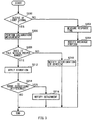
- FIG. 3 is a flowchart illustrating an example of a flow of the self-diagnosis process according to an example implementation of the invention. The process illustrated by way of example in FIG. 3 is executed before the collection process is performed.
- the self-diagnosis processor 136 may determine whether there is an output of a light signal. For example, the self-diagnosis processor 136 may cause the spectrum analyzer 120 to emit the light having the broadband spectrum, and may determine whether there is an output of the light signal from the spectrum analyzer 120 on the basis of the reception, by the light receiver of the spectrum analyzer 120, of the reflection light reflected by the gratings 118b.
- the process may proceed to step S202 if there is no output of the light signal (step S200: NO), in consideration of disconnection (or the breakage) in the fiber optic sensor 118.
- the process may proceed to step S206 if there is an output of the light signal (step S200: YES), in consideration of no disconnection in the fiber optic sensor 118.
- the self-diagnosis processor 136 may measure a response time.
- the self-diagnosis processor 136 may cause a spectrum analyzer (not illustrated), different from the spectrum analyzer 120 used for the collection process, to emit light, and may measure a time (i.e., the response time) until which the reflection light is received.
- the self-diagnosis processor 136 may use another spectrum analyzer in one example illustrated in FIG. 3 ; however, the spectrum analyzer 120 itself or any other measuring instrument may be used to measure the response time, as long as a time taken from the emission of light to the reception of the reflection light is measurable.
- a light signal based on reflection light reflected from a breakage portion is still measurable, even if the disconnection occurs in the fiber optic sensor 118 and the output of the light signal based on the reflection light reflected from the gratings 118b is absent at step S200 accordingly.
- the self-diagnosis processor 136 may identify a location at which the breakage occurs, on the basis of the principle of Optical Time Domain Reflectometer (OTDR) and on the basis of the time taken from the emission of light to reception of the light reflected from the breakage portion.
- OTDR Optical Time Domain Reflectometer
- the self-diagnosis processor 136 is able to identify whether the disconnection occurs in the sensor device, e.g., the gratings 118b, or whether the disconnection occurs in a cable part, e.g., the optical fiber.
- the self-diagnosis processor 136 may provide a notification on the breakage portion at step S204. In other words, the self-diagnosis processor 136 outputs an error. For example, the self-diagnosis processor 136 may cause the display 114 to display the identified breakage portion. The self-diagnosis process may end after performing step S204.
- the self-diagnosis processor 136 may perform a process related to calibration measurement. For example, the self-diagnosis processor 136 may cause the spectrum analyzer 120 to emit light having an intensity that is previously set for calibration purpose, and may cause the spectrum analyzer 120 to output a light signal based on the reflection light.
- the self-diagnosis processor 136 may determine whether an output value of the calibration falls within a proper range. For example, the self-diagnosis processor 136 may obtain a temperature near the structure measured by a thermometer (not illustrated). The self-diagnosis processor 136 may also calculate a stress that acts on the target TG of the structure, on the basis of a weight of the structure or a total weight of a loaded article mounted on the structure, both measured by a weight sensor (not illustrated), for example.
- the self-diagnosis processor 136 may read table information related to the proper range stored in the storage 110.
- the proper range of the calibration may be so set as to be associated with the stress and the temperature.
- the self-diagnosis processor 136 may identify, from the table information, the proper range that corresponds to the obtained temperature and to the calculated stress.
- the self-diagnosis processor 136 may determine whether the output value of the calibration falls within the proper range. The process may proceed to step S212 if the output value of the calibration falls within the proper range (step S208: YES), in consideration of no deterioration in the adhesive of the fiber optic sensor 118. The process may proceed to step S210 if the output value of the calibration falls outside the proper range (step S208: NO), in consideration of the deterioration in the adhesive of the fiber optic sensor 118.
- the self-diagnosis processor 136 may provide a notification on the deterioration in the adhesive. In other words, the self-diagnosis processor 136 outputs an error. For example, the self-diagnosis processor 136 may cause the display 114 to display a notification notifying that the adhesive of the fiber optic sensor 118 is deteriorated.
- the self-diagnosis process may end after performing step S210.
- the vibration controller 130 may apply the vibration.
- the vibration controller 130 may control the vibrator 116 to thereby vibrate or apply the vibration to the target TG.
- the self-diagnosis processor 136 may determine whether there is a significant difference. For example, the self-diagnosis processor 136 may cause, during the application of the vibration, the spectrum analyzer 120 to emit the light having the broadband spectrum, and may cause the spectrum analyzer 120 to detect the wavelength of the reflection light. Thereafter, the self-diagnosis processor 136 may determine whether the wavelength of the reflection light shows a significant difference with respect to a previous measurement value.
- step S214 YES
- step S214: NO the self-diagnosis process may end if there is no significant difference (step S214: NO), in consideration of no detachment of the adhesive of the fiber optic sensor 118.
- step S216 the self-diagnosis processor 136 may provide a notification on the detachment of the adhesive. In other words, the self-diagnosis processor 136 outputs an error. For example, the self-diagnosis processor 136 may cause the display 114 to display a notification notifying that the adhesive of the fiber optic sensor 118 is detached. The self-diagnosis process may end after performing step S216.
- the health diagnosis processor 134 may perform the health diagnosis process, if none of the errors are output upon the execution of the foregoing example self-diagnosis process.
- the diagnosis apparatus 100 makes a diagnosis related to whether the fiber optic sensor 118 itself functions normally, on the basis of the above-described example self-diagnosis process. This eliminates the necessity of providing human resources for making the diagnosis, making it possible to achieve full automation from the self-diagnosis process to the collection process and to the health diagnosis process.
- the diagnosis apparatus 100 makes it possible to perform the self-diagnosis process easily even in a situation where the fiber optic sensor 118 is positioned at a high altitude, or where examination is not performable unless any component of the structure is removed, making it possible to reduce a work burden.
- the fiber optic sensor 118 in the foregoing example implementation may utilize the fiber Bragg grating.
- the fiber optic sensor 118 may utilize any other scheme.
- the fiber optic sensor 118 may measure a physical quantity, a chemical quantity, or any other quantity of the target TG on the basis of a change in any other characteristic other than or in addition to the wavelength of the light.
- a characteristic may include an intensity, a phase, a frequency, and a polarization.
- the diagnosis apparatus 100 may include the health diagnosis processor 134. Providing the health diagnosis processor 134 helps to achieve the full automation from the self-diagnosis process to the collection process and to the health diagnosis process.
- the health diagnosis processor 134 is not necessarily an essential feature. In an alternative example implementation, the diagnosis apparatus 100 may not include the health diagnosis processor 134.
- the diagnosis apparatus 100 may include the vibrator 116. Providing the vibrator 116 helps to detect the damage in the health diagnosis process, and helps to detect the detachment of the adhesive in the self-diagnosis process.
- the vibrator 116 is not necessarily an essential feature. In an alternative example implementation, the diagnosis apparatus 100 may not include the vibrator 116.
- the proper range in the foregoing example implementation may be associated with one or both of the stress and the temperature.
- the stress and the temperature are greatly influential to the output value of the calibration.
- setting the proper range such that the proper range is associated with one or both of the stress and the temperature helps to evaluate the fiber optic sensor 118 appropriately.
- the proper range may, however, be associated with any other physical quantity other than or in addition to the stress and/or the temperature.
- the controller 122 illustrated in FIG. 1 is implementable by circuitry including at least one semiconductor integrated circuit such as at least one processor (e.g., a central processing unit (CPU)), at least one application specific integrated circuit (ASIC), and/or at least one field programmable gate array (FPGA).
- processor e.g., a central processing unit (CPU)
- ASIC application specific integrated circuit
- FPGA field programmable gate array
- At least one processor is configurable, by reading instructions from at least one machine readable non-transitory tangible medium, to perform all or a part of functions of the controller 122.
- a medium may take many forms, including, but not limited to, any type of magnetic medium such as a hard disk, any type of optical medium such as a CD and a DVD, any type of semiconductor memory (i.e., semiconductor circuit) such as a volatile memory and a non-volatile memory.
- the volatile memory may include a DRAM and a SRAM
- the nonvolatile memory may include a ROM and a NVRAM.
- the ASIC is an integrated circuit (IC) customized to perform
- the FPGA is an integrated circuit designed to be configured after manufacturing in order to perform, all or a part of the functions of the controller 122 illustrated in FIG. 1 .
Landscapes
- Physics & Mathematics (AREA)
- General Physics & Mathematics (AREA)
- Spectroscopy & Molecular Physics (AREA)
- Chemical & Material Sciences (AREA)
- Analytical Chemistry (AREA)
- Life Sciences & Earth Sciences (AREA)
- Health & Medical Sciences (AREA)
- Biochemistry (AREA)
- General Health & Medical Sciences (AREA)
- Immunology (AREA)
- Pathology (AREA)
- Investigating Or Analysing Materials By Optical Means (AREA)
- Optical Transform (AREA)
- Measurement Of Mechanical Vibrations Or Ultrasonic Waves (AREA)
- Measuring Temperature Or Quantity Of Heat (AREA)
Applications Claiming Priority (1)
| Application Number | Priority Date | Filing Date | Title |
|---|---|---|---|
| JP2018032200A JP6709241B2 (ja) | 2018-02-26 | 2018-02-26 | 診断装置 |
Publications (3)
| Publication Number | Publication Date |
|---|---|
| EP3531099A1 true EP3531099A1 (fr) | 2019-08-28 |
| EP3531099C0 EP3531099C0 (fr) | 2025-12-31 |
| EP3531099B1 EP3531099B1 (fr) | 2025-12-31 |
Family
ID=64172375
Family Applications (1)
| Application Number | Title | Priority Date | Filing Date |
|---|---|---|---|
| EP18204357.0A Active EP3531099B1 (fr) | 2018-02-26 | 2018-11-05 | Appareil de diagnostic |
Country Status (4)
| Country | Link |
|---|---|
| US (1) | US10585017B2 (fr) |
| EP (1) | EP3531099B1 (fr) |
| JP (1) | JP6709241B2 (fr) |
| CN (1) | CN110196072B (fr) |
Families Citing this family (3)
| Publication number | Priority date | Publication date | Assignee | Title |
|---|---|---|---|---|
| JP7365857B2 (ja) * | 2019-11-01 | 2023-10-20 | 株式会社Subaru | 機体搬送装置 |
| CN114441060B (zh) * | 2020-07-22 | 2026-01-23 | 深圳阿珂法先进科技有限公司 | 一种用于光纤传感器测温系统的自诊断合格检测方法 |
| US20240092406A1 (en) * | 2022-09-16 | 2024-03-21 | Matthew Younkins | Method to Manage Autonomous Vehicle Energy |
Citations (5)
| Publication number | Priority date | Publication date | Assignee | Title |
|---|---|---|---|---|
| JPS6159095B2 (fr) | 1984-03-19 | 1986-12-15 | Nippon Suisan Kaisha Ltd | |
| JP2005098921A (ja) | 2003-09-26 | 2005-04-14 | Fuji Heavy Ind Ltd | 構造用複合材料の損傷探知システム及び構造用複合材料の損傷探知方法 |
| JP2015075446A (ja) * | 2013-10-11 | 2015-04-20 | 株式会社デンソー | ライトセンサ |
| US20170082766A1 (en) * | 2014-05-16 | 2017-03-23 | Silixa Ltd. | Method and system for downhole object location and orientation determination |
| US20170370786A1 (en) * | 2014-12-22 | 2017-12-28 | Sikorsky Aircraft Corporation | Fiber optic weight sensor optimization for landing gear |
Family Cites Families (22)
| Publication number | Priority date | Publication date | Assignee | Title |
|---|---|---|---|---|
| JPS5930030A (ja) * | 1982-08-12 | 1984-02-17 | Omron Tateisi Electronics Co | 電子温度計 |
| US4592003A (en) | 1982-08-12 | 1986-05-27 | Omron Tateisi Electronics Co. | Measuring circuit device |
| JPH0810168B2 (ja) * | 1989-12-21 | 1996-01-31 | オムロン株式会社 | 電子体温計の表示方法 |
| JP2864825B2 (ja) * | 1991-12-20 | 1999-03-08 | 日立電線株式会社 | 物理量分布検出装置 |
| US5355208A (en) * | 1992-06-24 | 1994-10-11 | Mason & Hanger National, Inc. | Distributed fiber optic sensor for locating and identifying remote disturbances |
| JP3546653B2 (ja) * | 1997-08-06 | 2004-07-28 | 日立電線株式会社 | 光ファイバ式多点型物理量検出装置 |
| JP2000065887A (ja) * | 1998-08-20 | 2000-03-03 | Takaoka Electric Mfg Co Ltd | 電力機器の故障点標定装置 |
| US6606490B1 (en) * | 1999-08-10 | 2003-08-12 | Intel Corporation | Battery operated radio receivers having power save by reducing active reception time |
| JP2003344147A (ja) * | 2002-05-28 | 2003-12-03 | Fujikura Ltd | 光ファイバリング干渉型センサ |
| JPWO2007004466A1 (ja) * | 2005-07-01 | 2009-01-29 | シスメックス株式会社 | 分析装置 |
| JP4613741B2 (ja) * | 2005-08-05 | 2011-01-19 | トヨタ自動車株式会社 | 車両用データ記録装置 |
| JP2007178258A (ja) * | 2005-12-28 | 2007-07-12 | Yokogawa Electric Corp | 光スペクトラムアナライザおよびこれを用いた光ファイバセンサシステム |
| JP2011036462A (ja) * | 2009-08-12 | 2011-02-24 | Hoya Corp | 医療用観察システム |
| US9789313B2 (en) * | 2011-02-23 | 2017-10-17 | John D. LIPANI | System and methods for diagnosis and treatment of discogenic lower back pain |
| CN103778312B (zh) * | 2012-10-24 | 2017-05-10 | 中兴通讯股份有限公司 | 远程家庭保健系统 |
| JP6159095B2 (ja) | 2013-02-05 | 2017-07-05 | 株式会社Subaru | 変位計測装置及び変位計測方法 |
| EP3060965B1 (fr) * | 2013-10-22 | 2019-12-04 | Nidec Motor Corporation | Codeur de diagnostic de machine |
| US10973462B2 (en) * | 2014-05-04 | 2021-04-13 | Scott J. Rapp | Fiber optic based devices and methods for monitoring soft tissue |
| JP6137705B2 (ja) * | 2015-02-02 | 2017-05-31 | 株式会社Subaru | 失火判定装置 |
| GB201502025D0 (en) * | 2015-02-06 | 2015-03-25 | Optasence Holdings Ltd | Optical fibre sensing |
| CN106092159B (zh) * | 2016-05-27 | 2018-12-28 | 重庆大学 | 具解调结果可信度自诊断功能的光纤光栅传感方法 |
| CN106130644B (zh) | 2016-07-20 | 2018-04-03 | 上海交通大学 | 基于色散过补偿的频域均衡方法 |
-
2018
- 2018-02-26 JP JP2018032200A patent/JP6709241B2/ja active Active
- 2018-11-05 EP EP18204357.0A patent/EP3531099B1/fr active Active
- 2018-12-20 US US16/227,356 patent/US10585017B2/en active Active
-
2019
- 2019-01-22 CN CN201910057353.8A patent/CN110196072B/zh active Active
Patent Citations (5)
| Publication number | Priority date | Publication date | Assignee | Title |
|---|---|---|---|---|
| JPS6159095B2 (fr) | 1984-03-19 | 1986-12-15 | Nippon Suisan Kaisha Ltd | |
| JP2005098921A (ja) | 2003-09-26 | 2005-04-14 | Fuji Heavy Ind Ltd | 構造用複合材料の損傷探知システム及び構造用複合材料の損傷探知方法 |
| JP2015075446A (ja) * | 2013-10-11 | 2015-04-20 | 株式会社デンソー | ライトセンサ |
| US20170082766A1 (en) * | 2014-05-16 | 2017-03-23 | Silixa Ltd. | Method and system for downhole object location and orientation determination |
| US20170370786A1 (en) * | 2014-12-22 | 2017-12-28 | Sikorsky Aircraft Corporation | Fiber optic weight sensor optimization for landing gear |
Also Published As
| Publication number | Publication date |
|---|---|
| US10585017B2 (en) | 2020-03-10 |
| JP2019148462A (ja) | 2019-09-05 |
| JP6709241B2 (ja) | 2020-06-10 |
| EP3531099C0 (fr) | 2025-12-31 |
| US20190265126A1 (en) | 2019-08-29 |
| CN110196072B (zh) | 2023-07-21 |
| EP3531099B1 (fr) | 2025-12-31 |
| CN110196072A (zh) | 2019-09-03 |
Similar Documents
| Publication | Publication Date | Title |
|---|---|---|
| EP3531099B1 (fr) | Appareil de diagnostic | |
| JP6159095B2 (ja) | 変位計測装置及び変位計測方法 | |
| WO2015199590A1 (fr) | Système de capteur à fibre optique pour détecter des changements de température dans un aéronef | |
| US6659640B2 (en) | Fiber optic temperature measurement system and method | |
| JP7418225B2 (ja) | ピペットの検証手順 | |
| EP3575767B1 (fr) | Système d'inspection optique, procédé d'inspection optique et structure d'aéronef | |
| CN117367620A (zh) | 温度测定装置以及温度测定方法 | |
| JP7360415B2 (ja) | 診断装置 | |
| US11155365B2 (en) | Aircraft management system | |
| CN104990649A (zh) | 一种简易钢绞线预应力测量装置及方法 | |
| JP3837124B2 (ja) | 情報取得装置および評価設備 | |
| CN110654566A (zh) | 航空器管理系统 | |
| JP4768405B2 (ja) | 光ファイバセンサー及び歪・温度観測システム | |
| JP2016176858A (ja) | 光ファイバ温度測定装置、光ファイバの温度測定方法及び光ファイバの温度測定プログラム | |
| JP5197054B2 (ja) | ひずみ計測装置及びその計測方法 | |
| JP6957277B2 (ja) | 光測定装置、検査装置および光測定方法 | |
| EP3978892B1 (fr) | Méthode de mesure des forces qui agissent sur une structure et/ou de la température dans la structure | |
| CN117029713A (zh) | 机床主轴形变监测系统、方法、设备及介质 | |
| CN119245776A (zh) | 一种渐变色转盘取信计量表及其自动校准方法、系统 | |
| KR20120040944A (ko) | 타이어 공정에서 열전대의 정도 및 감도 자동 검수 장치 |
Legal Events
| Date | Code | Title | Description |
|---|---|---|---|
| PUAI | Public reference made under article 153(3) epc to a published international application that has entered the european phase |
Free format text: ORIGINAL CODE: 0009012 |
|
| STAA | Information on the status of an ep patent application or granted ep patent |
Free format text: STATUS: THE APPLICATION HAS BEEN PUBLISHED |
|
| AK | Designated contracting states |
Kind code of ref document: A1 Designated state(s): AL AT BE BG CH CY CZ DE DK EE ES FI FR GB GR HR HU IE IS IT LI LT LU LV MC MK MT NL NO PL PT RO RS SE SI SK SM TR |
|
| AX | Request for extension of the european patent |
Extension state: BA ME |
|
| STAA | Information on the status of an ep patent application or granted ep patent |
Free format text: STATUS: REQUEST FOR EXAMINATION WAS MADE |
|
| 17P | Request for examination filed |
Effective date: 20200226 |
|
| RBV | Designated contracting states (corrected) |
Designated state(s): AL AT BE BG CH CY CZ DE DK EE ES FI FR GB GR HR HU IE IS IT LI LT LU LV MC MK MT NL NO PL PT RO RS SE SI SK SM TR |
|
| STAA | Information on the status of an ep patent application or granted ep patent |
Free format text: STATUS: EXAMINATION IS IN PROGRESS |
|
| 17Q | First examination report despatched |
Effective date: 20220523 |
|
| GRAP | Despatch of communication of intention to grant a patent |
Free format text: ORIGINAL CODE: EPIDOSNIGR1 |
|
| STAA | Information on the status of an ep patent application or granted ep patent |
Free format text: STATUS: GRANT OF PATENT IS INTENDED |
|
| INTG | Intention to grant announced |
Effective date: 20250701 |
|
| GRAS | Grant fee paid |
Free format text: ORIGINAL CODE: EPIDOSNIGR3 |
|
| GRAA | (expected) grant |
Free format text: ORIGINAL CODE: 0009210 |
|
| STAA | Information on the status of an ep patent application or granted ep patent |
Free format text: STATUS: THE PATENT HAS BEEN GRANTED |
|
| AK | Designated contracting states |
Kind code of ref document: B1 Designated state(s): AL AT BE BG CH CY CZ DE DK EE ES FI FR GB GR HR HU IE IS IT LI LT LU LV MC MK MT NL NO PL PT RO RS SE SI SK SM TR |
|
| REG | Reference to a national code |
Ref country code: CH Ref legal event code: F10 Free format text: ST27 STATUS EVENT CODE: U-0-0-F10-F00 (AS PROVIDED BY THE NATIONAL OFFICE) Effective date: 20251231 Ref country code: GB Ref legal event code: FG4D |
|
| REG | Reference to a national code |
Ref country code: DE Ref legal event code: R096 Ref document number: 602018088237 Country of ref document: DE |
|
| REG | Reference to a national code |
Ref country code: IE Ref legal event code: FG4D |
|
| U01 | Request for unitary effect filed |
Effective date: 20260130 |
|
| U07 | Unitary effect registered |
Designated state(s): AT BE BG DE DK EE FI FR IT LT LU LV MT NL PT RO SE SI Effective date: 20260205 |
|
| PG25 | Lapsed in a contracting state [announced via postgrant information from national office to epo] |
Ref country code: NO Free format text: LAPSE BECAUSE OF FAILURE TO SUBMIT A TRANSLATION OF THE DESCRIPTION OR TO PAY THE FEE WITHIN THE PRESCRIBED TIME-LIMIT Effective date: 20260331 |
|
| PG25 | Lapsed in a contracting state [announced via postgrant information from national office to epo] |
Ref country code: HR Free format text: LAPSE BECAUSE OF FAILURE TO SUBMIT A TRANSLATION OF THE DESCRIPTION OR TO PAY THE FEE WITHIN THE PRESCRIBED TIME-LIMIT Effective date: 20251231 |
|
| PG25 | Lapsed in a contracting state [announced via postgrant information from national office to epo] |
Ref country code: RS Free format text: LAPSE BECAUSE OF FAILURE TO SUBMIT A TRANSLATION OF THE DESCRIPTION OR TO PAY THE FEE WITHIN THE PRESCRIBED TIME-LIMIT Effective date: 20260331 |