EP3534206B1 - Génération sonore de type à vibrations de panneau afficheur - Google Patents
Génération sonore de type à vibrations de panneau afficheur Download PDFInfo
- Publication number
- EP3534206B1 EP3534206B1 EP19168786.2A EP19168786A EP3534206B1 EP 3534206 B1 EP3534206 B1 EP 3534206B1 EP 19168786 A EP19168786 A EP 19168786A EP 3534206 B1 EP3534206 B1 EP 3534206B1
- Authority
- EP
- European Patent Office
- Prior art keywords
- display panel
- sound generating
- cover bottom
- display device
- sound
- Prior art date
- Legal status (The legal status is an assumption and is not a legal conclusion. Google has not performed a legal analysis and makes no representation as to the accuracy of the status listed.)
- Active
Links
Images












Classifications
-
- H—ELECTRICITY
- H04—ELECTRIC COMMUNICATION TECHNIQUE
- H04R—LOUDSPEAKERS, MICROPHONES, GRAMOPHONE PICK-UPS OR LIKE ACOUSTIC ELECTROMECHANICAL TRANSDUCERS; ELECTRIC HEARING AIDS; PUBLIC ADDRESS SYSTEMS
- H04R1/00—Details of transducers, loudspeakers or microphones
- H04R1/20—Arrangements for obtaining desired frequency or directional characteristics
- H04R1/32—Arrangements for obtaining desired frequency or directional characteristics for obtaining desired directional characteristic only
- H04R1/323—Arrangements for obtaining desired frequency or directional characteristics for obtaining desired directional characteristic only for loudspeakers
-
- H—ELECTRICITY
- H04—ELECTRIC COMMUNICATION TECHNIQUE
- H04R—LOUDSPEAKERS, MICROPHONES, GRAMOPHONE PICK-UPS OR LIKE ACOUSTIC ELECTROMECHANICAL TRANSDUCERS; ELECTRIC HEARING AIDS; PUBLIC ADDRESS SYSTEMS
- H04R9/00—Transducers of moving-coil, moving-strip, or moving-wire type
- H04R9/06—Loudspeakers
-
- G—PHYSICS
- G02—OPTICS
- G02F—OPTICAL DEVICES OR ARRANGEMENTS FOR THE CONTROL OF LIGHT BY MODIFICATION OF THE OPTICAL PROPERTIES OF THE MEDIA OF THE ELEMENTS INVOLVED THEREIN; NON-LINEAR OPTICS; FREQUENCY-CHANGING OF LIGHT; OPTICAL LOGIC ELEMENTS; OPTICAL ANALOGUE/DIGITAL CONVERTERS
- G02F1/00—Devices or arrangements for the control of the intensity, colour, phase, polarisation or direction of light arriving from an independent light source, e.g. switching, gating or modulating; Non-linear optics
- G02F1/01—Devices or arrangements for the control of the intensity, colour, phase, polarisation or direction of light arriving from an independent light source, e.g. switching, gating or modulating; Non-linear optics for the control of the intensity, phase, polarisation or colour
- G02F1/13—Devices or arrangements for the control of the intensity, colour, phase, polarisation or direction of light arriving from an independent light source, e.g. switching, gating or modulating; Non-linear optics for the control of the intensity, phase, polarisation or colour based on liquid crystals, e.g. single liquid crystal display cells
- G02F1/133—Constructional arrangements; Operation of liquid crystal cells; Circuit arrangements
- G02F1/1333—Constructional arrangements; Manufacturing methods
-
- G—PHYSICS
- G06—COMPUTING OR CALCULATING; COUNTING
- G06F—ELECTRIC DIGITAL DATA PROCESSING
- G06F1/00—Details not covered by groups G06F3/00 - G06F13/00 and G06F21/00
- G06F1/16—Constructional details or arrangements
- G06F1/1601—Constructional details related to the housing of computer displays, e.g. of CRT monitors, of flat displays
- G06F1/1605—Multimedia displays, e.g. with integrated or attached speakers, cameras, microphones
-
- G—PHYSICS
- G09—EDUCATION; CRYPTOGRAPHY; DISPLAY; ADVERTISING; SEALS
- G09F—DISPLAYING; ADVERTISING; SIGNS; LABELS OR NAME-PLATES; SEALS
- G09F9/00—Indicating arrangements for variable information in which the information is built-up on a support by selection or combination of individual elements
- G09F9/30—Indicating arrangements for variable information in which the information is built-up on a support by selection or combination of individual elements in which the desired character or characters are formed by combining individual elements
-
- G—PHYSICS
- G09—EDUCATION; CRYPTOGRAPHY; DISPLAY; ADVERTISING; SEALS
- G09F—DISPLAYING; ADVERTISING; SIGNS; LABELS OR NAME-PLATES; SEALS
- G09F9/00—Indicating arrangements for variable information in which the information is built-up on a support by selection or combination of individual elements
- G09F9/30—Indicating arrangements for variable information in which the information is built-up on a support by selection or combination of individual elements in which the desired character or characters are formed by combining individual elements
- G09F9/313—Indicating arrangements for variable information in which the information is built-up on a support by selection or combination of individual elements in which the desired character or characters are formed by combining individual elements being gas discharge devices
-
- G—PHYSICS
- G09—EDUCATION; CRYPTOGRAPHY; DISPLAY; ADVERTISING; SEALS
- G09F—DISPLAYING; ADVERTISING; SIGNS; LABELS OR NAME-PLATES; SEALS
- G09F9/00—Indicating arrangements for variable information in which the information is built-up on a support by selection or combination of individual elements
- G09F9/30—Indicating arrangements for variable information in which the information is built-up on a support by selection or combination of individual elements in which the desired character or characters are formed by combining individual elements
- G09F9/35—Indicating arrangements for variable information in which the information is built-up on a support by selection or combination of individual elements in which the desired character or characters are formed by combining individual elements being liquid crystals
-
- H—ELECTRICITY
- H04—ELECTRIC COMMUNICATION TECHNIQUE
- H04R—LOUDSPEAKERS, MICROPHONES, GRAMOPHONE PICK-UPS OR LIKE ACOUSTIC ELECTROMECHANICAL TRANSDUCERS; ELECTRIC HEARING AIDS; PUBLIC ADDRESS SYSTEMS
- H04R1/00—Details of transducers, loudspeakers or microphones
- H04R1/02—Casings; Cabinets ; Supports therefor; Mountings therein
- H04R1/025—Arrangements for fixing loudspeaker transducers, e.g. in a box, furniture
-
- H—ELECTRICITY
- H04—ELECTRIC COMMUNICATION TECHNIQUE
- H04R—LOUDSPEAKERS, MICROPHONES, GRAMOPHONE PICK-UPS OR LIKE ACOUSTIC ELECTROMECHANICAL TRANSDUCERS; ELECTRIC HEARING AIDS; PUBLIC ADDRESS SYSTEMS
- H04R1/00—Details of transducers, loudspeakers or microphones
- H04R1/02—Casings; Cabinets ; Supports therefor; Mountings therein
- H04R1/028—Casings; Cabinets ; Supports therefor; Mountings therein associated with devices performing functions other than acoustics, e.g. electric candles
-
- H—ELECTRICITY
- H04—ELECTRIC COMMUNICATION TECHNIQUE
- H04R—LOUDSPEAKERS, MICROPHONES, GRAMOPHONE PICK-UPS OR LIKE ACOUSTIC ELECTROMECHANICAL TRANSDUCERS; ELECTRIC HEARING AIDS; PUBLIC ADDRESS SYSTEMS
- H04R7/00—Diaphragms for electromechanical transducers; Cones
- H04R7/02—Diaphragms for electromechanical transducers; Cones characterised by the construction
- H04R7/04—Plane diaphragms
- H04R7/045—Plane diaphragms using the distributed mode principle, i.e. whereby the acoustic radiation is emanated from uniformly distributed free bending wave vibration induced in a stiff panel and not from pistonic motion
-
- H—ELECTRICITY
- H04—ELECTRIC COMMUNICATION TECHNIQUE
- H04R—LOUDSPEAKERS, MICROPHONES, GRAMOPHONE PICK-UPS OR LIKE ACOUSTIC ELECTROMECHANICAL TRANSDUCERS; ELECTRIC HEARING AIDS; PUBLIC ADDRESS SYSTEMS
- H04R9/00—Transducers of moving-coil, moving-strip, or moving-wire type
- H04R9/02—Details
-
- H—ELECTRICITY
- H04—ELECTRIC COMMUNICATION TECHNIQUE
- H04R—LOUDSPEAKERS, MICROPHONES, GRAMOPHONE PICK-UPS OR LIKE ACOUSTIC ELECTROMECHANICAL TRANSDUCERS; ELECTRIC HEARING AIDS; PUBLIC ADDRESS SYSTEMS
- H04R9/00—Transducers of moving-coil, moving-strip, or moving-wire type
- H04R9/02—Details
- H04R9/025—Magnetic circuit
-
- H—ELECTRICITY
- H04—ELECTRIC COMMUNICATION TECHNIQUE
- H04R—LOUDSPEAKERS, MICROPHONES, GRAMOPHONE PICK-UPS OR LIKE ACOUSTIC ELECTROMECHANICAL TRANSDUCERS; ELECTRIC HEARING AIDS; PUBLIC ADDRESS SYSTEMS
- H04R9/00—Transducers of moving-coil, moving-strip, or moving-wire type
- H04R9/02—Details
- H04R9/04—Construction, mounting, or centering of coil
-
- H—ELECTRICITY
- H10—SEMICONDUCTOR DEVICES; ELECTRIC SOLID-STATE DEVICES NOT OTHERWISE PROVIDED FOR
- H10K—ORGANIC ELECTRIC SOLID-STATE DEVICES
- H10K59/00—Integrated devices, or assemblies of multiple devices, comprising at least one organic light-emitting element covered by group H10K50/00
- H10K59/10—OLED displays
-
- G—PHYSICS
- G02—OPTICS
- G02F—OPTICAL DEVICES OR ARRANGEMENTS FOR THE CONTROL OF LIGHT BY MODIFICATION OF THE OPTICAL PROPERTIES OF THE MEDIA OF THE ELEMENTS INVOLVED THEREIN; NON-LINEAR OPTICS; FREQUENCY-CHANGING OF LIGHT; OPTICAL LOGIC ELEMENTS; OPTICAL ANALOGUE/DIGITAL CONVERTERS
- G02F1/00—Devices or arrangements for the control of the intensity, colour, phase, polarisation or direction of light arriving from an independent light source, e.g. switching, gating or modulating; Non-linear optics
- G02F1/01—Devices or arrangements for the control of the intensity, colour, phase, polarisation or direction of light arriving from an independent light source, e.g. switching, gating or modulating; Non-linear optics for the control of the intensity, phase, polarisation or colour
- G02F1/13—Devices or arrangements for the control of the intensity, colour, phase, polarisation or direction of light arriving from an independent light source, e.g. switching, gating or modulating; Non-linear optics for the control of the intensity, phase, polarisation or colour based on liquid crystals, e.g. single liquid crystal display cells
- G02F1/133—Constructional arrangements; Operation of liquid crystal cells; Circuit arrangements
- G02F1/1333—Constructional arrangements; Manufacturing methods
- G02F1/133308—Support structures for LCD panels, e.g. frames or bezels
-
- G—PHYSICS
- G09—EDUCATION; CRYPTOGRAPHY; DISPLAY; ADVERTISING; SEALS
- G09G—ARRANGEMENTS OR CIRCUITS FOR CONTROL OF INDICATING DEVICES USING STATIC MEANS TO PRESENT VARIABLE INFORMATION
- G09G2310/00—Command of the display device
- G09G2310/08—Details of timing specific for flat panels, other than clock recovery
-
- G—PHYSICS
- G09—EDUCATION; CRYPTOGRAPHY; DISPLAY; ADVERTISING; SEALS
- G09G—ARRANGEMENTS OR CIRCUITS FOR CONTROL OF INDICATING DEVICES USING STATIC MEANS TO PRESENT VARIABLE INFORMATION
- G09G3/00—Control arrangements or circuits, of interest only in connection with visual indicators other than cathode-ray tubes
- G09G3/20—Control arrangements or circuits, of interest only in connection with visual indicators other than cathode-ray tubes for presentation of an assembly of a number of characters, e.g. a page, by composing the assembly by combination of individual elements arranged in a matrix no fixed position being assigned to or needed to be assigned to the individual characters or partial characters
- G09G3/22—Control arrangements or circuits, of interest only in connection with visual indicators other than cathode-ray tubes for presentation of an assembly of a number of characters, e.g. a page, by composing the assembly by combination of individual elements arranged in a matrix no fixed position being assigned to or needed to be assigned to the individual characters or partial characters using controlled light sources
- G09G3/30—Control arrangements or circuits, of interest only in connection with visual indicators other than cathode-ray tubes for presentation of an assembly of a number of characters, e.g. a page, by composing the assembly by combination of individual elements arranged in a matrix no fixed position being assigned to or needed to be assigned to the individual characters or partial characters using controlled light sources using electroluminescent panels
- G09G3/32—Control arrangements or circuits, of interest only in connection with visual indicators other than cathode-ray tubes for presentation of an assembly of a number of characters, e.g. a page, by composing the assembly by combination of individual elements arranged in a matrix no fixed position being assigned to or needed to be assigned to the individual characters or partial characters using controlled light sources using electroluminescent panels semiconductive, e.g. using light-emitting diodes [LED]
- G09G3/3208—Control arrangements or circuits, of interest only in connection with visual indicators other than cathode-ray tubes for presentation of an assembly of a number of characters, e.g. a page, by composing the assembly by combination of individual elements arranged in a matrix no fixed position being assigned to or needed to be assigned to the individual characters or partial characters using controlled light sources using electroluminescent panels semiconductive, e.g. using light-emitting diodes [LED] organic, e.g. using organic light-emitting diodes [OLED]
- G09G3/3225—Control arrangements or circuits, of interest only in connection with visual indicators other than cathode-ray tubes for presentation of an assembly of a number of characters, e.g. a page, by composing the assembly by combination of individual elements arranged in a matrix no fixed position being assigned to or needed to be assigned to the individual characters or partial characters using controlled light sources using electroluminescent panels semiconductive, e.g. using light-emitting diodes [LED] organic, e.g. using organic light-emitting diodes [OLED] using an active matrix
-
- G—PHYSICS
- G09—EDUCATION; CRYPTOGRAPHY; DISPLAY; ADVERTISING; SEALS
- G09G—ARRANGEMENTS OR CIRCUITS FOR CONTROL OF INDICATING DEVICES USING STATIC MEANS TO PRESENT VARIABLE INFORMATION
- G09G3/00—Control arrangements or circuits, of interest only in connection with visual indicators other than cathode-ray tubes
- G09G3/20—Control arrangements or circuits, of interest only in connection with visual indicators other than cathode-ray tubes for presentation of an assembly of a number of characters, e.g. a page, by composing the assembly by combination of individual elements arranged in a matrix no fixed position being assigned to or needed to be assigned to the individual characters or partial characters
- G09G3/22—Control arrangements or circuits, of interest only in connection with visual indicators other than cathode-ray tubes for presentation of an assembly of a number of characters, e.g. a page, by composing the assembly by combination of individual elements arranged in a matrix no fixed position being assigned to or needed to be assigned to the individual characters or partial characters using controlled light sources
- G09G3/30—Control arrangements or circuits, of interest only in connection with visual indicators other than cathode-ray tubes for presentation of an assembly of a number of characters, e.g. a page, by composing the assembly by combination of individual elements arranged in a matrix no fixed position being assigned to or needed to be assigned to the individual characters or partial characters using controlled light sources using electroluminescent panels
- G09G3/32—Control arrangements or circuits, of interest only in connection with visual indicators other than cathode-ray tubes for presentation of an assembly of a number of characters, e.g. a page, by composing the assembly by combination of individual elements arranged in a matrix no fixed position being assigned to or needed to be assigned to the individual characters or partial characters using controlled light sources using electroluminescent panels semiconductive, e.g. using light-emitting diodes [LED]
- G09G3/3208—Control arrangements or circuits, of interest only in connection with visual indicators other than cathode-ray tubes for presentation of an assembly of a number of characters, e.g. a page, by composing the assembly by combination of individual elements arranged in a matrix no fixed position being assigned to or needed to be assigned to the individual characters or partial characters using controlled light sources using electroluminescent panels semiconductive, e.g. using light-emitting diodes [LED] organic, e.g. using organic light-emitting diodes [OLED]
- G09G3/3266—Details of drivers for scan electrodes
-
- G—PHYSICS
- G09—EDUCATION; CRYPTOGRAPHY; DISPLAY; ADVERTISING; SEALS
- G09G—ARRANGEMENTS OR CIRCUITS FOR CONTROL OF INDICATING DEVICES USING STATIC MEANS TO PRESENT VARIABLE INFORMATION
- G09G3/00—Control arrangements or circuits, of interest only in connection with visual indicators other than cathode-ray tubes
- G09G3/20—Control arrangements or circuits, of interest only in connection with visual indicators other than cathode-ray tubes for presentation of an assembly of a number of characters, e.g. a page, by composing the assembly by combination of individual elements arranged in a matrix no fixed position being assigned to or needed to be assigned to the individual characters or partial characters
- G09G3/22—Control arrangements or circuits, of interest only in connection with visual indicators other than cathode-ray tubes for presentation of an assembly of a number of characters, e.g. a page, by composing the assembly by combination of individual elements arranged in a matrix no fixed position being assigned to or needed to be assigned to the individual characters or partial characters using controlled light sources
- G09G3/30—Control arrangements or circuits, of interest only in connection with visual indicators other than cathode-ray tubes for presentation of an assembly of a number of characters, e.g. a page, by composing the assembly by combination of individual elements arranged in a matrix no fixed position being assigned to or needed to be assigned to the individual characters or partial characters using controlled light sources using electroluminescent panels
- G09G3/32—Control arrangements or circuits, of interest only in connection with visual indicators other than cathode-ray tubes for presentation of an assembly of a number of characters, e.g. a page, by composing the assembly by combination of individual elements arranged in a matrix no fixed position being assigned to or needed to be assigned to the individual characters or partial characters using controlled light sources using electroluminescent panels semiconductive, e.g. using light-emitting diodes [LED]
- G09G3/3208—Control arrangements or circuits, of interest only in connection with visual indicators other than cathode-ray tubes for presentation of an assembly of a number of characters, e.g. a page, by composing the assembly by combination of individual elements arranged in a matrix no fixed position being assigned to or needed to be assigned to the individual characters or partial characters using controlled light sources using electroluminescent panels semiconductive, e.g. using light-emitting diodes [LED] organic, e.g. using organic light-emitting diodes [OLED]
- G09G3/3275—Details of drivers for data electrodes
-
- H—ELECTRICITY
- H04—ELECTRIC COMMUNICATION TECHNIQUE
- H04R—LOUDSPEAKERS, MICROPHONES, GRAMOPHONE PICK-UPS OR LIKE ACOUSTIC ELECTROMECHANICAL TRANSDUCERS; ELECTRIC HEARING AIDS; PUBLIC ADDRESS SYSTEMS
- H04R2400/00—Loudspeakers
- H04R2400/03—Transducers capable of generating both sound as well as tactile vibration, e.g. as used in cellular phones
-
- H—ELECTRICITY
- H04—ELECTRIC COMMUNICATION TECHNIQUE
- H04R—LOUDSPEAKERS, MICROPHONES, GRAMOPHONE PICK-UPS OR LIKE ACOUSTIC ELECTROMECHANICAL TRANSDUCERS; ELECTRIC HEARING AIDS; PUBLIC ADDRESS SYSTEMS
- H04R2400/00—Loudspeakers
- H04R2400/11—Aspects regarding the frame of loudspeaker transducers
-
- H—ELECTRICITY
- H04—ELECTRIC COMMUNICATION TECHNIQUE
- H04R—LOUDSPEAKERS, MICROPHONES, GRAMOPHONE PICK-UPS OR LIKE ACOUSTIC ELECTROMECHANICAL TRANSDUCERS; ELECTRIC HEARING AIDS; PUBLIC ADDRESS SYSTEMS
- H04R2499/00—Aspects covered by H04R or H04S not otherwise provided for in their subgroups
- H04R2499/10—General applications
- H04R2499/11—Transducers incorporated or for use in hand-held devices, e.g. mobile phones, PDA's, camera's
-
- H—ELECTRICITY
- H04—ELECTRIC COMMUNICATION TECHNIQUE
- H04R—LOUDSPEAKERS, MICROPHONES, GRAMOPHONE PICK-UPS OR LIKE ACOUSTIC ELECTROMECHANICAL TRANSDUCERS; ELECTRIC HEARING AIDS; PUBLIC ADDRESS SYSTEMS
- H04R2499/00—Aspects covered by H04R or H04S not otherwise provided for in their subgroups
- H04R2499/10—General applications
- H04R2499/15—Transducers incorporated in visual displaying devices, e.g. televisions, computer displays, laptops
-
- H—ELECTRICITY
- H04—ELECTRIC COMMUNICATION TECHNIQUE
- H04R—LOUDSPEAKERS, MICROPHONES, GRAMOPHONE PICK-UPS OR LIKE ACOUSTIC ELECTROMECHANICAL TRANSDUCERS; ELECTRIC HEARING AIDS; PUBLIC ADDRESS SYSTEMS
- H04R5/00—Stereophonic arrangements
- H04R5/02—Spatial or constructional arrangements of loudspeakers
-
- H—ELECTRICITY
- H04—ELECTRIC COMMUNICATION TECHNIQUE
- H04R—LOUDSPEAKERS, MICROPHONES, GRAMOPHONE PICK-UPS OR LIKE ACOUSTIC ELECTROMECHANICAL TRANSDUCERS; ELECTRIC HEARING AIDS; PUBLIC ADDRESS SYSTEMS
- H04R7/00—Diaphragms for electromechanical transducers; Cones
- H04R7/02—Diaphragms for electromechanical transducers; Cones characterised by the construction
- H04R7/04—Plane diaphragms
-
- H—ELECTRICITY
- H04—ELECTRIC COMMUNICATION TECHNIQUE
- H04R—LOUDSPEAKERS, MICROPHONES, GRAMOPHONE PICK-UPS OR LIKE ACOUSTIC ELECTROMECHANICAL TRANSDUCERS; ELECTRIC HEARING AIDS; PUBLIC ADDRESS SYSTEMS
- H04R9/00—Transducers of moving-coil, moving-strip, or moving-wire type
- H04R9/02—Details
- H04R9/04—Construction, mounting, or centering of coil
- H04R9/041—Centering
- H04R9/043—Inner suspension or damper, e.g. spider
-
- H—ELECTRICITY
- H04—ELECTRIC COMMUNICATION TECHNIQUE
- H04R—LOUDSPEAKERS, MICROPHONES, GRAMOPHONE PICK-UPS OR LIKE ACOUSTIC ELECTROMECHANICAL TRANSDUCERS; ELECTRIC HEARING AIDS; PUBLIC ADDRESS SYSTEMS
- H04R9/00—Transducers of moving-coil, moving-strip, or moving-wire type
- H04R9/06—Loudspeakers
- H04R9/063—Loudspeakers using a plurality of acoustic drivers
Definitions
- the present disclosure relates to a display device and, more specifically, to a display device for generating sound by directly vibrating a display panel thereof.
- the flat panel display devices which are being researched, include a Liquid Crystal Display Device, a Plasma Display Panel, a Field Emission Display Device, a Light Emitting Diode Display Device, and an Organic Light Emitting Diode Display Device.
- the Liquid Crystal Display (LCD) device includes: an array substrate including a thin film transistor; an upper substrate including a color filter and/or a black matrix, etc.; and a liquid crystal material layer formed therebetween, wherein an alignment state of the liquid crystal layer is controlled according to an electric field applied between opposite electrodes of a pixel area, and thereby the transmittance of light is adjusted to display an image.
- LCD Liquid Crystal Display
- an Active Area (AA) configured to provide an image to a user and a Non-active Area (NA), which is a peripheral area of the Active Area (AA), are defined.
- the display panel is usually manufactured by attaching a first substrate, which is an array substrate having a thin film transistor formed therein to define a pixel area, and a second substrate, which is an upper substrate having a black matrix and/or color filter layer formed thereon, to each other.
- the array substrate or first substrate, on which a thin film transistor is formed includes a plurality of gate lines GS extending in a first direction and a plurality of data lines DL extending in a second direction perpendicular to the first direction, and one pixel area P is defined by each gate line and each data line.
- One or more thin film transistors are formed in one pixel area P, and gate and source electrodes of each thin film transistor may be connected to a gate line and a data line, respectively.
- the liquid crystal display device does not have its own light-emitting element and thus needs a separate light source. Therefore, the liquid crystal display device has a back-light unit having a light source, such as an LED, which is arranged at the rear surface thereof and irradiates a light toward a front surface of the liquid crystal panel thereof, thereby at last implementing a recognizable image.
- a light source such as an LED
- an Organic Light Emitting Diode (OLED) display device recently coming into the spotlight as a display device has advantages of a fast response rate, a high light emitting efficiency, a high luminance and a wide viewing angle because of using an OLED which emits light by itself.
- the organic light emitting diode display device sub-pixels including organic light emitting diodes are arranged in a matrix form, and the brightness of sub-pixels selected by a scan signal is controlled according to a gray scale of data. Further, the organic light emitting diode display device, which is an emissive element, consumes small power and has a high response speed, a high light emitting efficiency, a high luminance, and a wide viewing angle.
- a set apparatus or finished product including such a display device as described above may include, for example, a television (TV), a computer monitor, and an advertising panel.
- TV television
- computer monitor a television
- advertising panel an advertising panel
- Such a display device or set apparatus includes a sound output device, such as a speaker, for generating and outputting sound relating to an image.
- a sound output device such as a speaker
- a company which manufactures a display device such as a liquid crystal display device or an organic light emitting diode display device, manufactures only a display panel or display device, while another company which manufactures a speaker assembles the speaker with the manufactured display device, so as to finally complete a set apparatus capable of outputting an image and sound.
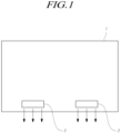
- FIG. 1 is a schematic plan view of a speaker included in a conventional display device.
- the conventional display device 1 includes a speaker 2 disposed at a rear or lower part of a display panel thereof.
- the sound generated by the speaker 2 does not progress toward a viewer, who is viewing an image from the front side of the display device 1, but progresses toward the rear side or the underside of the display panel rather than the display panel on which the image is being displayed. Therefore, the sound may disturb the viewer's immersion.
- the sound quality may be degraded due to an interference with sound reflected by a wall or floor.
- US 9 137 592 B2 discloses an apparatus including a frame; and a speaker connected to the frame.
- US 2012/243719 Al discloses electronic devices that contain flexible displays and one or more display-based speaker structures.
- EP 1 507 438 A2 discloses a sound reproduction device which includes a front panel, a case and an electromechanical acoustic transducer.
- JP 2009 100223 A discloses an oscillating actuator attached to a display panel.
- EP 2 947 857 A2 discloses a display apparatus including a display panel which displays an image and a vibration member attached to a surface of the display panel, where the vibration member receives a sound signal, generates a vibration in response to the sound signal, and transfers the vibration to the display panel to allow the display panel to output a sound.
- US2006140439 A1 discloses a method of mounting a flat panel speaker.
- the present disclosure has been made to overcome the above-mentioned problems of the prior art and, in one aspect, is to provide a panel vibration type sound generating display device, which can generate sound by directly vibrating a display panel configuring the display device.
- the present disclosure is to provide a display device including a panel vibration type sound generating apparatus, which has a predetermined air gap formed between a display panel and a sound generating actuator and an actuator support hole formed in a support structure of the display device, so that the display device has a reduced thickness while having an excellent sound generation performance.
- the support structure may also be termed a support member or support part.
- the present disclosure is to provide a display device having a sound generation baffle part formed therein, which includes an adhesive member (double-sided tape) attached between the upper surface of the support structure and the lower surface of the display panel and a sealing part disposed outside the adhesive member, so that the display device has an improved sound output characteristic.
- an adhesive member double-sided tape
- the present disclosure is to provide a display device in which a sound generating actuator is placed at a first position of a support structure of the display device and a set PCB of a set apparatus is placed at a second position different from the first position, so as to avoid interference between the sound generating actuator and the set PCB.
- the present disclosure is to provide a display device, which has a reinforcement member arranged inside the support structure of the display device when two or more sound generating actuators are used, so that the display device can prevent deformation of the support structure due to different vibration characteristics of the two or more sound generating actuators.
- a display device of the present embodiment includes: a display panel configured to display an image; and a sound generating actuator connected to a surface of the display panel configured to vibrate the display panel to generate sound.
- the surface may be an inner surface, for example.
- the display device further includes a support structure comprising a cover bottom, configured to cover and support at least a rear surface of the display panel, wherein the sound generating actuator is inserted in and fixed to a support hole formed at the cover bottom.
- the sound generating actuator may include: a plate inserted in the support hole; a magnet disposed on the plate; a center pole disposed at a center of the plate; a bobbin disposed to surround the center pole and be in contact with the display panel; and a coil wound around the bobbin.
- the plate may be a lower plate, for example.
- the lower plate configuring the sound generating actuator further includes an extension part extending outward, and the extension part may be fixed to the lower surface of the cover bottom through a bolt, a PEM TM nut, or an adhesive member.
- a recessed part may be formed on an upper surface of the cover bottom opposite to the source PCB placed on a rear surface of the display panel, and a first buffer member spaced a predetermined distance from the lower surface of the display panel may be disposed on the recessed part.
- the recessed part may be concave, for example.
- the cover bottom may have a second buffer member disposed thereon, which is in contact with the lower surface of the display panel and the upper surfaces of the cover bottom while separating a first area covering the source PCB and a second area covering the sound generating actuator.
- the sound generating actuator may include two or more actuators, which are symmetrically arranged and have different vibration characteristics, and the cover bottom may further have a reinforcement member disposed thereon, which passes through adjacent positions of the two or more actuators.
- An embodiment of the present disclosure as described above provides a display device including a panel vibration type sound generating display device, which generates sound by directly vibrating a display panel, thereby making it unnecessary to install a separate speaker to the display device or a set apparatus including the display device.
- the display device or the set apparatus can improve the sound localization or sound output characteristics, can achieve easy designing of the mechanism of the set apparatus, and has a reduced thickness thereof.
- the display device has a predetermined air gap formed between the display panel and the sound generating actuator, and the sound generating actuator inserted in and fixed to a support hole formed at a support structure of the display device. Therefore, the display device has an excellent sound generation performance while having a reduced thickness.
- the display device has a baffle part, which may include an adhesive member (double-sided tape) attached between the upper surface of the support structure and the lower surface of the display panel and a sealing part disposed outside the adhesive member, and thus can minimize the sound leakage and thus can improve the sound generating performance.
- a baffle part which may include an adhesive member (double-sided tape) attached between the upper surface of the support structure and the lower surface of the display panel and a sealing part disposed outside the adhesive member, and thus can minimize the sound leakage and thus can improve the sound generating performance.
- the arrangement of one or more buffer members between a source PCB of the display panel and the support structure disposed at the rear surface of the display panel to fix/support the sound generating actuator or between the inner surface of the support structure and the rear surface of the display panel adjacent to the source PCB can prevent generation of interference and noise between the support structure of the display device and a source PCB (S-PCB) for driving the display panel.
- S-PCB source PCB
- the arrangement of a reinforcement member inside the support structure of the display device using two or more sound generating actuators can prevent deformation of the support structure due to different vibrations of the two or more sound generating actuators or sound distortion by the vibration of the support structure.
- a panel vibration type sound generating display device comprising: a display panel to display an image; and a sound generating actuator connected to a surface of the display panel and configured to vibrate the display panel to generate sound.
- the panel vibration type sound generating display device further comprises a support structure configured to cover and support at least a rear surface of the display panel, wherein the sound generating actuator is inserted in a support hole disposed at the support structure to be fixed to the support structure.
- the sound generating actuator of the panel vibration type sound generating display device may further comprise: a lower plate inserted in the support hole; a magnet disposed on the lower plate; a center pole disposed at a center of the lower plate; a bobbin disposed to surround the center pole and be in contact with the display panel; and a coil wound around the bobbin.
- the support structure of the panel vibration type sound generating display device comprises a cover bottom, the lower plate further including an extension part extending outward, and the extension part being fixed to a lower surface of the cover bottom.
- the extension part and the cover bottom of the panel vibration type sound generating display device may be fixedly coupled to each other by one of a bolt fastened through a through-hole provided through the extension part to a screw hole disposed at the cover bottom and an adhesive member disposed between the extension part and the cover bottom.
- the panel vibration type sound generating display device further comprises a baffle part disposed between the support structure and the lower surface of the display panel to define an air gap, which is a space in which the display panel can be vibrated by the sound generating actuator.
- the baffle part of the panel vibration type sound generating display device may comprise an adhesive member disposed at an edge of the air gap and attached to the lower surface of the display panel and the upper surface of the support structure, and a sealing part disposed outside the adhesive member.
- the sealing part of the panel vibration type sound generating display device may have a thickness larger than the thickness of the adhesive member.
- the support structure of the panel vibration type sound generating display device comprises a cover bottom, which supports a rear side of the display panel, and a middle cabinet, which has a shape of a frame, coupled to the cover bottom to support a side surface of the display panel, and stably holds the edge of the display panel, the middle cabinet comprising an area division member configured to separate a first area including a source PCB for driving the display panel and a second area including the sound generating actuator.
- the panel vibration type sound generating display device may further comprise a set PCB, which is disposed at an outer rear surface of the cover bottom and includes a control circuit configured to control the entire display device, wherein a cable passing hole through which a connection cable for electrically connecting the source PCB and the set PCB is to pass is disposed at an area of the cover bottom corresponding to the first area.
- the support structure of the panel vibration type sound generating display device comprises a cover bottom supporting the rear side of the display panel, a source PCB for driving the display panel is disposed on a rear surface of one side of the display panel, and a first buffer member spaced from the source PCB by a predetermined distance is placed on an inner surface of the cover bottom corresponding to the source PCB.
- a display device includes a display panel 100 configured to display an image, and a sound generating actuator 200 which is attached to a surface of the display panel and vibrates the display panel to generate sound.
- an LCM or OLED module configured by a display panel and a driving unit thereof may be expressed as a "display device" of a narrow meaning
- an electronic apparatus, as a finished product, including such an LCM or OLED module may be expressed as a "set apparatus".
- the display device in a narrow meaning may include an LCD or OLED display panel and a source PCB, which is a control unit for driving the display panel
- the set apparatus may further include a set PCB, which is a set control unit electrically connected to the source PCB to control the entire set apparatus.
- the display panel 100 used in the present embodiment includes all types of display panels including a liquid crystal display panel, an Organic Light Emitting Diode (OLED) display panel, and a Plasma Display Panel (PDP) and is not limited to a specific display panel, as long as the display panel is directly vibrated by the sound generating actuator 200 to generate sound wave.
- OLED Organic Light Emitting Diode
- PDP Plasma Display Panel
- the display panel When the display panel is a liquid crystal display panel, the display panel may include: a plurality of gate lines; a plurality of data lines; pixels defined at intersecting areas between the gate lines and data lines; an array substrate including a thin-film transistor, which is a switching device configured to adjust a light transmission degree at each pixel; an upper substrate including a color filter and/or a black matrix, etc.; and a liquid crystal material layer formed therebetween.
- the display panel may include: a plurality of gate lines; a plurality of data lines; pixels defined at intersecting areas between the gate lines and data lines; an array substrate including a thin-film transistor, which is a switching device configured to selectively apply a voltage to each pixel; an OLED layer disposed on the array substrate; and a sealing substrate or an encapsulation substrate disposed on the array substrate to cover the OLED layer.
- the sealing substrate protects the thin film transistor and the OLED layer from an external impact and prevents moisture from permeating the OLED layer.
- the display panel is an OLED display panel by the reasons described below.
- a liquid crystal display panel has many laminated layers and requires an indirect light source type back-light having a separate light source disposed therein. Therefore, when the liquid crystal display panel is directly vibrated by the sound generating actuator 200, the directivity of the liquid crystal material may be shaken and thus cause distortion of an image.
- the OLED display panel since the OLED device of the OLED display panel is an emissive element, the OLED display panel does not require a separate light source and has one panel in which multiple layers including a polarization layer, a glass layer, and an encapsulation layer are integrated. Therefore, even when the OLED display panel is directly vibrated by the sound generating actuator 200, the vibration has nearly no influence on the light emitting property of the organic light emitting layer and thus causes no image distortion. Therefore, in the present embodiment, it is preferred to use an OLED display panel.
- the display panel used in a display device according to the present embodiment has a general structure, so a more specific description thereof will be omitted.
- the display device further includes a baffle part 400 configured to form an air gap, which is a space disposed between the display panel and the cover bottom 300 to transfer the generated sound wave.
- the air gap is defined as an area sealed in all directions, and such a sealed air gap may be expressed as a baffle structure.
- the adhesive part 412 may be configured by a double sided tape, it is preferred that the height of the sealing part 414 is higher than the height of the adhesive part 412 as described below in more detail with reference to FIGs. 7A to 7C .
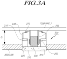
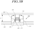
- FIGs. 3A and 3B are sectional views of two types of sound generating actuators used according to embodiments of the present disclosure.
- a sound generating actuator 200 used in the present embodiment may include a magnet 220, which is a permanent magnet, plates 210 and 210' configured to support the magnet, a center pole 230 protruding from a central area of the plate 210, a bobbin 250 disposed to surround the center pole 230, and a coil 260 wound around the bobbin, wherein an electric current for generating sound is applied to the coil 260.
- a magnet 220 which is a permanent magnet
- plates 210 and 210' configured to support the magnet
- a center pole 230 protruding from a central area of the plate 210
- a bobbin 250 disposed to surround the center pole 230
- a coil 260 wound around the bobbin wherein an electric current for generating sound is applied to the coil 260.
- the sound generating actuator used in the present embodiment may include both a first structure in which the magnet is disposed outside the coil and a second structure in which the magnet is disposed inside the coil.
- FIG. 3A illustrates the first structure having the magnet disposed outside the coil, which may be called a dynamic type or an external magnet type.
- the lower plate 210 is fixed to a support hole 310 formed at the cover bottom 300 and the magnet 220, which is a permanent magnet having an annular shape, is disposed outside the lower plate.
- the upper plate 210' is disposed on the magnet 220, and an external frame 240 protruding from the upper plate is disposed outside the upper plate.
- the center pole 230 protrudes from the central area of the lower plate 210 and the bobbin 250 surrounds the center pole 230.
- the magnet 220 disposed between the lower plate 210 and the upper plate 210' can be fixedly supported.
- the damper 270 is disposed between the external frame 240 and the bobbin.
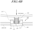
- the bobbin moves upward and the display panel coupled to the distal end of the bobbin moves upward, as shown in FIG. 4A .
- FIGs. 5A and 5B illustrate an example of a coupling state between a sound generating actuator according to an embodiment of the present disclosure and a cover bottom, which is a supporting structure of a display device.
- a support hole 310 is formed through the cover bottom 300, and at least one among the lower plate 210 of the sound generating actuator 200, the magnet 220, and the upper plate 210' is inserted and received in the support hole.
- An extension part 212 extending outward from the lower plate is additionally formed on the lower surface of the lower plate 210, and the extension part 212 is fixed to the lower surface of the cover bottom 310 to allow the sound generating actuator 200 to be mounted to the cover bottom.
- the distance between the display panel and the cover bottom can be reduced to thereby reduce the thickness of the display device.
- the sound generating actuator inserted in/fixed to the support hole of the cover bottom can minimize the air gap due to the reduced height of the sound generating actuator disposed between the rear surface of the display panel and the innner surface of the cover bottom.
- a screw hole is formed on the rear surface of the cover bottom, and a bolt 320 or a screw is fastened through the screw hole formed through the extension part 212 of the lower plate to the screw hole of the cover bottom to fix the sound generating actuator to the cover bottom.
- a PEM TM nut 330 or self-clinching nut is placed to secure a predetermined distance between the cover bottom 300 and the extension part 212 of the lower plate, and the actuator is then fixed by the bolt 320.
- PEM nut 330 or self-clinching nut as shown in FIG. 6B can secure a predetermined space between the sound generating actuator and the cover bottom and thus can minimize the transferring of the vibration of the actuator to the cover bottom.
- an adhesive member such as a double-sided tape, is disposed between the cover bottom and the extension part 212 of the lower plate of the actuator to attach and fix them to each other.
- the adhesive member as shown in FIG. 6B has a properly adjusted elasticity and thickness, the adhesive member can function as a kind of damper to minimize the transferring of the vibration of the actuator to the cover bottom.
- the structure as shown in FIGs. 5A to 6B in which the sound generating actuator 200 attached to the display panel to directly vibrate the display panel is inserted in and fixed to a support hole formed through the cover bottom can reduced the thickness of the display device in comparison with the structure in which the actuator is completely received in the display device.
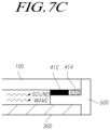
- FIGs. 7A to 7C illustrate an example of a baffle part formed between a display panel and a middle cabinet, which is one of structures for supporting the display panel, in order to form an air gap between the display panel, which serves as a vibrating plate, and a cover bottom.
- the panel vibration type sound generating apparatus should secure an air gap 600, which is a space allowing the panel to be vibrated by the sound generating apparatus 200, between the display panel 100 and a support structure (cover bottom 300).
- the support structure of the display device includes a middle cabinet 500, which is coupled to the cover bottom and is configured to allow a part of the display panel to be stably placed thereon, in addition to the cover bottom 300 covering the entire rear surface of the display panel.
- the middle cabinet 500 is a frame-shaped member formed along the outer periphery of the display panel, and includes a horizontal support part 502 on which a part of the display panel is stably placed, and a vertical support part 504 bent perpendicularly in opposite directions from the horizontal support part to cover the side surface of the cover bottom and the side surface of the display panel. Therefore, the middle cabinet may have a shape of a letter "T" in general.
- the adhesive member 412 configuring the baffle part 400 is a double-sided tape disposed between the upper surface of the horizontal support part of the middle cabinet 500 and the display panel and fixes the lower surfaces of the display panel to the middle cabinet.
- the sealing part 414 configuring the baffle part is placed outside of the adhesive member and preferably has a thickness or height larger than the thickness or height of the adhesive member.
- the sealing part 414 may be made from a material, such as rubber having a large elasticity, and has a thickness t2 larger than the thickness t1 of the adhesive member 412 as illustrated in FIG. 7B .
- one adhesive surface of the adhesive member 412 which is a double-sided tape having a thickness t1 is attached to the inner part of the upper surface of the horizontal support part 502 of the middle cabinet 500, and the sealing part 414 made of an elastic material having a thickness larger than t1 is disposed outside the adhesive member.
- the display panel 100 is attached to the other adhesive surface of the adhesive member 412. Then, the display panel is attached to the middle cabinet while pressing, to a certain degree, the sealing part 414 having the larger thickness. ( FIG. 7C )
- the structure illustrated in FIG. 7C in which the display panel 100 and the cover bottom 300 are coupled to each other while forming the air gap 600 to be as wide as the thickness of the adhesive member 412 and the horizontal support part 502 of the middle cabinet can secure a vibration space in which the display panel can generate sound, and can prevent the internally generated sound wave from leaking to the outside along the side surface of the display device.
- the baffle part 400 disposed at an edge of the air gap which has a double structure of the adhesive member 412 and the sealing part 414 while allowing the sealing part to have a larger thickness, can further enhance the sealing of the air gap and prevent leakage of the sound.
- the middle cabinet 500 used in the present specification may be replaced by another term, such as a guide panel, a plastic chassis, a p-chassis, a support main, a main support, or a mold frame, and includes all types of members, which are structures having a shape of a four-sided frame and having a sectional shape including multiple bent portions and are connected to the cover bottom to be used to support the display panel and the baffle part.
- the middle cabinet 500 may be made of synthetic resin, such as polycarbonate, by injection molding, without being limited thereto.
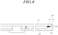
- FIG. 8 illustrates a structure of a baffle part which is not an embodiment of the claimed invention in which the adhesive member and the sealing part are placed directly on a cover bottom.
- the middle cabinet may not be always required.
- FIG. 8 shows a structure in which the cover bottom 300 supports one side of the display panel while forming an external appearance of the side surface of the display device without a middle cabinet.
- the structure illustrated in FIG. 8 includes a cover bottom 300 in which a step portion 360 protrudes upward from a base surface at one side of the cover bottom 300 and a side surface supporting part 362 vertically extends from the outside of the step portion 360.
- the adhesive member 412 in the form of a double-sided tape is disposed inside the step portion 360 of the cover bottom and the sealing part 414 having a thickness larger than that of the adhesive member is disposed outside the adhesive member.
- the display panel 100 is placed on the step portion 360 of the cover bottom and is attached to one adhesive surface of the adhesive member 412, so that the display panel is coupled to the cover bottom. Then, the sealing part 414 is compressed to secure and enhance the sealing of the air gap for transfer of sound.
- the thickness G of the air gap in consideration of the quantity of vibration of the display panel by the sound generating actuator, the range of sound to be output, and the quantity of output. It has been confirmed that an optimum thickness of the air gap G is about 2.0 mm.
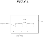
- FIGs. 9A and 9B illustrate a locational relation between a source PCB for driving a display panel and a set PCB for driving a set apparatus, which are arranged at the rear surface of a display device.
- the display device includes a source PCB, which is a circuit board including a Source Driver Integrated Circuit (S-DIC) for driving a display panel to drive data lines formed on the display panel and is referred to as simply "S-PCB".
- S-DIC Source Driver Integrated Circuit
- the controller supplies various control signals to the data driver and the gate driver to control the data driver and the gate driver, starts scanning according to a timing implemented in each frame, converts image data input from the outside into a data signal format used in the data driver and outputs a converted image data, and properly controls the driving of the data driver according the scanning.
- Each Source Driver Integrated Circuit may be connected to a bonding pad of an OLED display panel either by a Tape Automated Bonding (TAB) method or a Chip On Glass (COG) method or directly.
- S-DICs may be integrated and arranged in an OLED panel. Further, each S-DIC may be packaged on a film connected to an OLED display panel by a Chip On Film (COF) method.
- TAB Tape Automated Bonding
- COG Chip On Glass
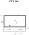
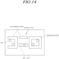
- FIGs. 10A and 10B has a structure, which further includes an area division member 510 configured to partition the middle cabinet into two or more areas and has a baffle part formed on the area division member, in order to solve the problems of the structure described above with reference to FIGs. 9A and 9B .
- an area division member 510 is lengthily disposed in the horizontal direction of the display device, and an adhesive member 412 and a sealing part 414 are arranged on the upper side of the area division member 510 and three sides of the middle cabinet corresponding to the second area B.
- FIG. 10B is a sectional view taken along line I-I' of FIG. 10A , in which the adhesive member 412 and the sealing part 414 are arranged on the upper side of the area division member 510 to seal the second area B as an air gap.
- a cable passing hole 370 through which a connection cable 810 connecting the source PCB 700 and the set PCB 800 is to pass, is formed in the first area A including the source PCB.
- FIGs. 10A and 10B The structure as shown in FIGs. 10A and 10B in which only the second area B including no source PCB is formed as a sound generating area can minimize the degradation of the sealing of the sound generating area by interference of the source PCB.
- the cable passing hole 370 disposed in the first area A including the source PCB can prevent the sound leakage through the cable passing hole.
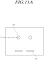
- a gap g is formed between the source PCB and the cover bottom in the area in which the source PCB is disposed, and is smaller than a gap between the source PCB and the cover bottom in the other area.
- the source PCB integrally vibrating the display panel may collide with the cover bottom in the area in which the source PCB is placed.
- the collision between the source PCB and the cover bottom may generate noise and may even damage the source PCB.
- the strong vibration of the display panel at the time of sound generation may have an influence on the performance of the source PCB when the vibration is continuously transferred to the source PCB.
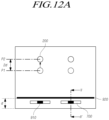
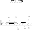
- FIGs. 12A and 12B illustrate an embodiment including a buffer member capable of preventing interference and noise between the source PCB and the cover bottom illustrated in FIGs. 11A and 11B .
- a source PCB 700 including a circuit element for driving the display panel is disposed at the rear surface of the display panel, a recessed part 380 is formed in an area of the cover bottom, which faces the source PCB, and a first buffer member 910 having a predetermined elasticity is placed on the upper surface of the concave part 380.
- the recessed part 380 may be concave, for example.
- a second buffer member 920 lengthily extending along one direction may be additionally disposed on the cover bottom.
- the display panel may be divided into a first area A covering the source PCB and a second area B covering the sound generating actuator, and the second buffer member 920 is preferably disposed to lengthily extend to separate the first area A and the second area B from each other.
- baffle part 400 including the adhesive member 412 and the sealing part 414 described above with reference to FIGs. 7A to 8 may be disposed on all of the four sides of the display panel in the embodiment of FIGs. 12A and 12B .
- the first buffer member 910 and the second buffer member 920 may be configured by a one-sided tape or double-sided tape.
- the buffer member may include all types of members formed of rubber, plastic, paper, or other materials, which have a predetermined elasticity.
- first buffer member 910 is disposed on the concave part 380 of the cover bottom while the upper surface of the first buffer member 910 is spaced a predetermined distance apart from the source PCB and the second buffer member 920 has one surface in contact with the cover bottom and the other surface in contact with the lower surface of the display panel.
- the first buffer member 910 may be placed on a part of the upper surface of the cover bottom, which faces the source PCB.
- the concave part 380 formed at the cover bottom area corresponding to the source PCB increases the gap between the source PCB and the cover bottom to reduce the possibility that the source PCB may collide with the cover bottom even when the display panel vibrates to generate sound.
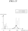
- the first buffer member 910 disposed on the concave part 380 of the cover bottom can buffer a large vibration of the display panel even when the source PCB moves toward the concave part of the cover bottom due to the large vibration, so as to reduce the generation of noise due to interference between the source PCB and the cover bottom and reduce the possibility of damage of the source PCB.
- the second buffer member 920 can prevent the vibration from being transferred to the source PCB 700 disposed on the rear surface of the display panel to some degree, and thus can minimize the degradation of performance of the source PCB due to continuous vibration of the display panel.
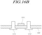
- FIGs. 16A and 16B which has a reinforcement member disposed inside a support structure of a display device while using two or more sound generating actuators is proposed.
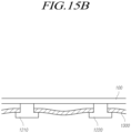
- At least one reinforcement member 1310 may be disposed inside or outside of the cover bottom in order to prevent deformation of the cover bottom or sound distortion by the unbalanced vibration of the cover bottom in the case of using multiple sound generating actuators having different vibration characteristics as described with reference to FIGs. 15A and 15B .
- the reinforcement member 1310 may be manufactured in the form of a separate metal bar and is then attached to the inner surface of the cover bottom as shown in FIG. 16B , to which the present disclosure is not limited.
- the cover bottom may be manufactured through injection molding, and may have a reinforcement member 1310 integrally formed by protruding a part of the inner surface of the cover bottom.
- the reinforcement member 1310 is not inevitably disposed on the inner surface of the cover bottom, but may be disposed on the outer surface of the cover bottom. However, in consideration of an external appearance and the thickness of the display device, it is preferred that the reinforcement member is disposed on the inner surface of the cover bottom 1300.
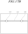
- FIGs. 17A and 17B illustrate specific arrangements of reinforcement members on a cover bottom.
- FIG. 17A illustrates a structure in which three sound generating actuators are arranged at each of the left side and right side thereof and two reinforcement members 1310 and 1310' are arranged, wherein a first reinforcement member 1310 is disposed to extend through middle points Q-Q' of segments, each of which connects to two upper actuators among the three left or right sound generating actuators, and a second reinforcement member 1310' is disposed to extend through middle points S-S' of segments, each of which connects to two lower actuators among the three left or right sound generating actuators.
- the symmetric arrangement of two or more sound generating actuators having different vibration characteristics as described above can prevent deformation (twisting) of the cover bottom due to the different vibration characteristics of the sound generating actuators or sound distortion by the vibration of the cover bottom.
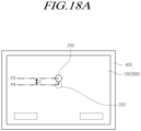
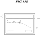
- FIG. 18A illustrates a state in which a sound generating actuator 200 is disposed at an initial position P3 having an optimal sound output characteristic.
- the sound generating actuator may have to be moved by a predetermined distance D from the initial position P3 in order to maintain the upper end portion to be slim or by reasons relating to design or arrangement of parts.
- the mechanism of the set apparatus can be easily designed and the thickness of the display device or set apparatus can be reduced.
- the display device has an excellent sound generation performance while having a reduced thickness.
Landscapes
- Physics & Mathematics (AREA)
- Engineering & Computer Science (AREA)
- Signal Processing (AREA)
- Acoustics & Sound (AREA)
- General Physics & Mathematics (AREA)
- Nonlinear Science (AREA)
- Theoretical Computer Science (AREA)
- Crystallography & Structural Chemistry (AREA)
- Chemical & Material Sciences (AREA)
- Mathematical Physics (AREA)
- Optics & Photonics (AREA)
- General Engineering & Computer Science (AREA)
- Multimedia (AREA)
- Computer Hardware Design (AREA)
- Otolaryngology (AREA)
- Health & Medical Sciences (AREA)
- Human Computer Interaction (AREA)
- Details Of Audible-Bandwidth Transducers (AREA)
- Diaphragms For Electromechanical Transducers (AREA)
- Piezo-Electric Transducers For Audible Bands (AREA)
- Devices For Indicating Variable Information By Combining Individual Elements (AREA)
- Audible-Bandwidth Dynamoelectric Transducers Other Than Pickups (AREA)
Claims (6)
- Dispositif d'affichage à génération de son du type à vibration de panneau comprenant :un panneau d'affichage (100) pour afficher une image ;un actionneur de génération de son (200) connecté à une surface du panneau d'affichage et configuré pour faire vibrer le panneau d'affichage (100) afin de générer un son ;une structure de support comprenant un couvercle inférieur et une armoire du milieu, dans lequel une couche d'air est prévue entre le couvercle inférieur et le panneau d'affichage (100) ; etune partie déflecteur (400) disposée entre l'armoire du milieu (500) et le panneau d'affichage (100) pour entourer la couche d'air, couplant ainsi de manière étanche le panneau d'affichage au couvercle inférieur ;l'armoire du milieu (500) supportant un bord du panneau d'affichage, l'armoire du milieu (500) comprenant un élément de division en zones (510) agencé pour séparer un espace entre le couvercle inférieur et le panneau d'affichage en une première zone et une deuxième zone, la première zone incluant une carte de circuit imprimé source (700) et la deuxième zone incluant l'actionneur de génération de son (200),le couvercle inférieur (300) étant configuré pour couvrir et supporter une surface arrière du panneau d'affichage (100),le couvercle inférieur (300) incluant en outre un trou de support (310), et l'actionneur de génération de son (200) étant logé dans le trou de support (310).
- Dispositif d'affichage selon la revendication 1, dans lequel l'actionneur de génération de son (200) comprend :une plaque (210) insérée dans le trou de support ;un aimant (220) disposé sur la plaque ;un pôle central (230) disposé sur la plaque ;une bobine (250) entourant le pôle central et connectée au panneau d'affichage ; etun serpentin (260) enroulé autour de la bobine.
- Dispositif d'affichage selon la revendication 2, dans lequel la plaque (210) inclut une partie d'extension (212) connectée à une surface extérieure du couvercle inférieur (300).
- Dispositif d'affichage selon l'une quelconque des revendications précédentes, comprenant en outre un autre actionneur de génération de son (200, 1210, 1210', 1220, 1220') connecté à la surface du panneau d'affichage (100) et configuré pour faire vibrer le panneau d'affichage (100) pour générer un son.
- Dispositif d'affichage selon la revendication 4, dans lequel les actionneurs de génération de son (200, 1210, 1210', 1220, 1220') sont agencés symétriquement au niveau de portions gauche et droite du panneau d'affichage et sont configurés pour être mis en vibration différemment de telle sorte qu'ils soient configurés pour générer un son stéréo.
- Dispositif d'affichage selon l'une quelconque des revendications 4 à 5, dans lequel les actionneurs de génération de son (200, 1210, 1210', 1220, 1220') sont configurés pour faire vibrer le panneau d'affichage (100) pour générer un son progressant dans une direction coïncidant avec une direction de sortie d'image du panneau d'affichage (100) pour localiser le son de sortie.
Priority Applications (1)
| Application Number | Priority Date | Filing Date | Title |
|---|---|---|---|
| EP25176643.2A EP4580211A3 (fr) | 2016-03-28 | 2016-07-26 | Dispositif d'affichage générant un son du type à vibration de panneau |
Applications Claiming Priority (2)
| Application Number | Priority Date | Filing Date | Title |
|---|---|---|---|
| KR1020160037118A KR101704517B1 (ko) | 2016-03-28 | 2016-03-28 | 패널 진동형 음향 발생 표시 장치 |
| EP16181185.6A EP3226069B1 (fr) | 2016-03-28 | 2016-07-26 | Génération sonore de type à vibrations de panneau afficheur |
Related Parent Applications (2)
| Application Number | Title | Priority Date | Filing Date |
|---|---|---|---|
| EP16181185.6A Division EP3226069B1 (fr) | 2016-03-28 | 2016-07-26 | Génération sonore de type à vibrations de panneau afficheur |
| EP16181185.6A Division-Into EP3226069B1 (fr) | 2016-03-28 | 2016-07-26 | Génération sonore de type à vibrations de panneau afficheur |
Related Child Applications (2)
| Application Number | Title | Priority Date | Filing Date |
|---|---|---|---|
| EP25176643.2A Division EP4580211A3 (fr) | 2016-03-28 | 2016-07-26 | Dispositif d'affichage générant un son du type à vibration de panneau |
| EP25176643.2A Division-Into EP4580211A3 (fr) | 2016-03-28 | 2016-07-26 | Dispositif d'affichage générant un son du type à vibration de panneau |
Publications (3)
| Publication Number | Publication Date |
|---|---|
| EP3534206A2 EP3534206A2 (fr) | 2019-09-04 |
| EP3534206A3 EP3534206A3 (fr) | 2019-12-11 |
| EP3534206B1 true EP3534206B1 (fr) | 2025-06-25 |
Family
ID=56618001
Family Applications (3)
| Application Number | Title | Priority Date | Filing Date |
|---|---|---|---|
| EP19168786.2A Active EP3534206B1 (fr) | 2016-03-28 | 2016-07-26 | Génération sonore de type à vibrations de panneau afficheur |
| EP16181185.6A Active EP3226069B1 (fr) | 2016-03-28 | 2016-07-26 | Génération sonore de type à vibrations de panneau afficheur |
| EP25176643.2A Pending EP4580211A3 (fr) | 2016-03-28 | 2016-07-26 | Dispositif d'affichage générant un son du type à vibration de panneau |
Family Applications After (2)
| Application Number | Title | Priority Date | Filing Date |
|---|---|---|---|
| EP16181185.6A Active EP3226069B1 (fr) | 2016-03-28 | 2016-07-26 | Génération sonore de type à vibrations de panneau afficheur |
| EP25176643.2A Pending EP4580211A3 (fr) | 2016-03-28 | 2016-07-26 | Dispositif d'affichage générant un son du type à vibration de panneau |
Country Status (5)
| Country | Link |
|---|---|
| US (5) | US10009683B2 (fr) |
| EP (3) | EP3534206B1 (fr) |
| JP (1) | JP6431889B2 (fr) |
| KR (1) | KR101704517B1 (fr) |
| CN (5) | CN111526463B (fr) |
Families Citing this family (133)
| Publication number | Priority date | Publication date | Assignee | Title |
|---|---|---|---|---|
| KR20170114471A (ko) * | 2016-04-05 | 2017-10-16 | 엘지디스플레이 주식회사 | 유기발광 표시 장치 |
| KR101704517B1 (ko) | 2016-03-28 | 2017-02-09 | 엘지디스플레이 주식회사 | 패널 진동형 음향 발생 표시 장치 |
| JP6873551B2 (ja) * | 2017-04-12 | 2021-05-19 | アルパイン株式会社 | 振動機構付き入力装置 |
| KR102373433B1 (ko) | 2017-04-29 | 2022-03-10 | 엘지디스플레이 주식회사 | 표시 장치 |
| KR102266209B1 (ko) | 2017-04-29 | 2021-06-16 | 엘지디스플레이 주식회사 | 디스플레이 장치 |
| KR102455490B1 (ko) * | 2017-04-29 | 2022-10-14 | 엘지디스플레이 주식회사 | 표시 장치 |
| KR102370839B1 (ko) | 2017-05-11 | 2022-03-04 | 엘지디스플레이 주식회사 | 표시장치 |
| KR102380627B1 (ko) * | 2017-05-29 | 2022-03-29 | 엘지디스플레이 주식회사 | 표시 장치 |
| KR102284718B1 (ko) * | 2017-05-31 | 2021-07-30 | 엘지디스플레이 주식회사 | 디스플레이 장치 |
| KR102266102B1 (ko) * | 2017-05-31 | 2021-06-16 | 엘지디스플레이 주식회사 | 표시 장치 |
| KR102308750B1 (ko) * | 2017-06-13 | 2021-10-01 | 엘지디스플레이 주식회사 | 표시 장치 |
| KR102312125B1 (ko) * | 2017-07-03 | 2021-10-12 | 엘지디스플레이 주식회사 | 표시장치 |
| KR102370183B1 (ko) * | 2017-07-12 | 2022-03-03 | 엘지디스플레이 주식회사 | 표시장치 |
| KR102308042B1 (ko) * | 2017-07-28 | 2021-09-30 | 엘지디스플레이 주식회사 | 표시장치 |
| KR101919454B1 (ko) | 2017-07-31 | 2018-11-16 | 엘지디스플레이 주식회사 | 디스플레이 장치 및 이를 이용한 컴퓨팅 장치 |
| KR102312266B1 (ko) | 2017-08-03 | 2021-10-12 | 엘지디스플레이 주식회사 | 표시장치 |
| KR102352563B1 (ko) | 2017-08-04 | 2022-01-17 | 엘지디스플레이 주식회사 | 표시장치 |
| KR102437513B1 (ko) * | 2017-08-10 | 2022-08-26 | 엘지디스플레이 주식회사 | 디스플레이 장치 |
| KR102446281B1 (ko) * | 2017-08-10 | 2022-09-21 | 엘지디스플레이 주식회사 | 디스플레이 장치 |
| KR102420554B1 (ko) * | 2017-08-10 | 2022-07-14 | 삼성디스플레이 주식회사 | 표시 패널, 브라켓 및 이를 포함하는 표시 장치 |
| KR102593965B1 (ko) * | 2017-09-11 | 2023-10-25 | 엘지디스플레이 주식회사 | 디스플레이 장치 |
| KR102366760B1 (ko) * | 2017-09-14 | 2022-02-22 | 엘지디스플레이 주식회사 | 표시장치 |
| CN109508086B (zh) * | 2017-09-15 | 2022-09-27 | 群创光电股份有限公司 | 显示设备 |
| KR102369719B1 (ko) * | 2017-09-21 | 2022-03-02 | 엘지디스플레이 주식회사 | 디스플레이 장치 |
| KR102356794B1 (ko) | 2017-09-27 | 2022-01-27 | 엘지디스플레이 주식회사 | 표시장치 |
| KR102366552B1 (ko) * | 2017-10-12 | 2022-02-23 | 삼성디스플레이 주식회사 | 패널 하부 부재 구조물 및 표시 장치 |
| KR102370166B1 (ko) * | 2017-10-24 | 2022-03-03 | 엘지디스플레이 주식회사 | 디스플레이 장치 |
| TWI688802B (zh) * | 2017-11-03 | 2020-03-21 | 曾世憲 | 畫素陣列及其製造方法 |
| KR102405215B1 (ko) * | 2017-11-06 | 2022-06-02 | 엘지디스플레이 주식회사 | 디스플레이 장치 |
| KR102489984B1 (ko) * | 2017-11-14 | 2023-01-17 | 엘지디스플레이 주식회사 | 디스플레이 장치 |
| KR102420817B1 (ko) * | 2017-11-20 | 2022-07-13 | 엘지디스플레이 주식회사 | 디스플레이 장치 |
| KR102402053B1 (ko) * | 2017-11-30 | 2022-05-24 | 엘지디스플레이 주식회사 | 디스플레이 장치 |
| CN108124029A (zh) * | 2017-12-06 | 2018-06-05 | 北京小米移动软件有限公司 | 终端设备 |
| KR102490349B1 (ko) * | 2017-12-11 | 2023-01-18 | 엘지디스플레이 주식회사 | 전자 기기 |
| KR102388246B1 (ko) * | 2017-12-19 | 2022-04-19 | 엘지디스플레이 주식회사 | 표시장치와 이를 이용한 모바일 기기 |
| KR102455501B1 (ko) | 2017-12-20 | 2022-10-14 | 엘지디스플레이 주식회사 | 디스플레이 장치 |
| KR102430953B1 (ko) * | 2017-12-21 | 2022-08-09 | 삼성디스플레이 주식회사 | 패널 하부 부재 및 이를 포함하는 표시 장치 |
| KR102455559B1 (ko) * | 2017-12-26 | 2022-10-14 | 엘지디스플레이 주식회사 | 표시장치 |
| KR102605160B1 (ko) * | 2017-12-26 | 2023-11-22 | 엘지디스플레이 주식회사 | 표시장치 |
| KR102452462B1 (ko) * | 2017-12-26 | 2022-10-06 | 엘지디스플레이 주식회사 | 표시장치 |
| US11516425B2 (en) | 2017-12-28 | 2022-11-29 | Sony Corporation | Display apparatus |
| KR102612609B1 (ko) | 2017-12-29 | 2023-12-08 | 엘지디스플레이 주식회사 | 표시장치 |
| KR102455892B1 (ko) * | 2017-12-29 | 2022-10-17 | 엘지디스플레이 주식회사 | 전자 기기 |
| KR102416381B1 (ko) | 2017-12-29 | 2022-07-01 | 엘지디스플레이 주식회사 | 디스플레이 장치 |
| CN107995575A (zh) * | 2018-01-15 | 2018-05-04 | 京东方科技集团股份有限公司 | 显示面板、显示装置及显示面板的控制方法 |
| CN108334165B (zh) * | 2018-01-19 | 2022-01-14 | 瑞声科技(新加坡)有限公司 | 电子设备 |
| US10848874B2 (en) * | 2018-02-20 | 2020-11-24 | Google Llc | Panel audio loudspeaker electromagnetic actuator |
| US10456107B2 (en) * | 2018-02-20 | 2019-10-29 | General Electric Company | Ultrasound imaging device and method for transmitting audible sounds |
| US10841704B2 (en) | 2018-04-06 | 2020-11-17 | Google Llc | Distributed mode loudspeaker electromagnetic actuator with axially and radially magnetized circuit |
| KR102501909B1 (ko) * | 2018-04-20 | 2023-02-20 | 엘지디스플레이 주식회사 | 디스플레이 장치 |
| KR102386452B1 (ko) * | 2018-05-02 | 2022-04-14 | 삼성디스플레이 주식회사 | 표시 장치 |
| KR102514485B1 (ko) * | 2018-05-10 | 2023-03-24 | 엘지디스플레이 주식회사 | 디스플레이 장치 |
| KR102553104B1 (ko) * | 2018-08-01 | 2023-07-07 | 삼성디스플레이 주식회사 | 표시 장치 |
| KR102526888B1 (ko) * | 2018-08-14 | 2023-04-28 | 삼성디스플레이 주식회사 | 표시 장치와 그의 구동 방법 |
| KR102594577B1 (ko) | 2018-08-22 | 2023-10-25 | 엘지디스플레이 주식회사 | 디스플레이 장치 |
| KR102601564B1 (ko) * | 2018-09-05 | 2023-11-13 | 삼성디스플레이 주식회사 | 표시 장치 |
| CN110913319B (zh) * | 2018-09-18 | 2021-10-01 | 乐金显示有限公司 | 显示设备 |
| KR102530589B1 (ko) | 2018-09-20 | 2023-05-08 | 엘지디스플레이 주식회사 | 디스플레이 장치 및 이를 이용한 컴퓨팅 장치 |
| KR102608137B1 (ko) * | 2018-09-20 | 2023-11-29 | 엘지디스플레이 주식회사 | 표시 장치 |
| KR20200037003A (ko) | 2018-09-28 | 2020-04-08 | 삼성디스플레이 주식회사 | 표시 장치와 그의 구동 방법 |
| KR102514184B1 (ko) * | 2018-09-28 | 2023-03-24 | 엘지디스플레이 주식회사 | 표시장치 |
| KR102618969B1 (ko) * | 2018-10-02 | 2023-12-28 | 삼성디스플레이 주식회사 | 표시장치 |
| KR102625724B1 (ko) * | 2018-10-05 | 2024-01-15 | 엘지디스플레이 주식회사 | 표시장치 |
| KR102622979B1 (ko) | 2018-10-15 | 2024-01-08 | 엘지디스플레이 주식회사 | 표시 장치 |
| CN112970239B (zh) * | 2018-11-13 | 2022-06-14 | 华为技术有限公司 | 一种屏幕组件及终端设备 |
| KR102628490B1 (ko) * | 2018-11-13 | 2024-01-22 | 엘지디스플레이 주식회사 | 표시장치 |
| KR102629516B1 (ko) | 2018-11-13 | 2024-01-24 | 엘지디스플레이 주식회사 | 표시장치 |
| CN111290521B (zh) * | 2018-12-06 | 2022-10-28 | 鸿富锦精密工业(武汉)有限公司 | 触控模块化显示装置 |
| TWI677820B (zh) * | 2018-12-11 | 2019-11-21 | 友達光電股份有限公司 | 顯示裝置 |
| KR102696990B1 (ko) * | 2018-12-12 | 2024-08-19 | 엘지디스플레이 주식회사 | 전자 기기 |
| GB201820557D0 (en) * | 2018-12-17 | 2019-01-30 | Pss Belgium Nv | Inertial exciter |
| KR102650501B1 (ko) | 2018-12-31 | 2024-03-21 | 엘지디스플레이 주식회사 | 음향발생장치, 이를 포함하는 표시장치 및 차량용 장치 |
| US10951992B2 (en) * | 2018-12-31 | 2021-03-16 | Lg Display Co., Ltd. | Vibration generating device and display apparatus including the same |
| CN114898685A (zh) | 2018-12-31 | 2022-08-12 | 乐金显示有限公司 | 显示装置 |
| MY203968A (en) * | 2018-12-31 | 2024-07-26 | Sony Corp | Display device and speaker |
| CN111384293B (zh) * | 2018-12-31 | 2023-06-09 | 乐金显示有限公司 | 发光二极管显示装置 |
| KR102657713B1 (ko) * | 2019-01-18 | 2024-04-16 | 삼성디스플레이 주식회사 | 표시 장치용 보호 부재, 이를 포함하는 표시 장치 및 표시 장치용 보호 부재의 제조 방법 |
| KR102668665B1 (ko) * | 2019-01-30 | 2024-05-23 | 삼성디스플레이 주식회사 | 표시 장치 |
| KR102668284B1 (ko) * | 2019-02-01 | 2024-05-23 | 삼성디스플레이 주식회사 | 표시 장치 |
| US11710389B2 (en) * | 2019-02-22 | 2023-07-25 | Ck Materials Lab Co., Ltd. | Haptic providing device and method for converting sound signal to haptic signal |
| US11348567B2 (en) | 2019-02-25 | 2022-05-31 | Qualcomm Incorporated | Feedback control for display as sound emitter |
| US10782731B1 (en) * | 2019-02-28 | 2020-09-22 | Google Llc | Modal frequency shifting for loudspeaker devices |
| CN110047392B (zh) * | 2019-03-11 | 2021-02-02 | 武汉华星光电技术有限公司 | 一种显示装置 |
| KR102668405B1 (ko) * | 2019-03-15 | 2024-05-23 | 삼성디스플레이 주식회사 | 표시 장치 및 표시 장치의 구동 방법 |
| KR102662671B1 (ko) | 2019-03-29 | 2024-04-30 | 엘지디스플레이 주식회사 | 표시 장치 |
| EP3918445A4 (fr) | 2019-04-09 | 2022-04-06 | Samsung Electronics Co., Ltd. | Dispositif électronique comprenant un haut-parleur d'écran d'affichage |
| KR102708253B1 (ko) | 2019-05-28 | 2024-09-23 | 삼성디스플레이 주식회사 | 표시 장치 |
| CN112104957A (zh) * | 2019-06-17 | 2020-12-18 | 海信视像科技股份有限公司 | 电子设备 |
| KR102705131B1 (ko) | 2019-06-19 | 2024-09-10 | 삼성디스플레이 주식회사 | 표시 장치와 그의 음향 제공 방법 |
| KR102653775B1 (ko) * | 2019-07-04 | 2024-04-01 | 엘지디스플레이 주식회사 | 표시 장치 |
| KR102693630B1 (ko) | 2019-07-04 | 2024-08-08 | 엘지디스플레이 주식회사 | 표시 장치 |
| KR102708557B1 (ko) | 2019-07-09 | 2024-09-23 | 삼성디스플레이 주식회사 | 표시 장치 |
| US11948549B2 (en) | 2019-07-17 | 2024-04-02 | Sound Solutions International Co., Ltd. | Electromagnetic actuator for a display with improved spring arrangement and output device with said actuator |
| KR102689721B1 (ko) | 2019-07-22 | 2024-07-29 | 엘지디스플레이 주식회사 | 디스플레이 장치 및 이를 포함하는 차량 |
| US11902698B2 (en) * | 2019-07-31 | 2024-02-13 | Sony Group Corporation | Display apparatus |
| KR102770878B1 (ko) | 2019-08-09 | 2025-02-20 | 삼성디스플레이 주식회사 | 표시 장치 |
| CN112449291B (zh) * | 2019-08-28 | 2022-04-29 | 华为技术有限公司 | 音响单元和移动终端 |
| KR102937612B1 (ko) * | 2019-11-08 | 2026-03-10 | 엘지디스플레이 주식회사 | 디스플레이 장치 |
| CN112838103B (zh) * | 2019-11-22 | 2022-07-22 | 京东方科技集团股份有限公司 | 一种显示面板及其制备方法、显示装置 |
| KR102808319B1 (ko) | 2019-11-27 | 2025-05-14 | 엘지디스플레이 주식회사 | 표시장치 |
| EP3840408A1 (fr) * | 2019-12-20 | 2021-06-23 | Continental Engineering Services GmbH | Actionneur destiné à la génération de bruit de structure |
| KR102737713B1 (ko) | 2019-12-27 | 2024-12-02 | 엘지디스플레이 주식회사 | 디스플레이 장치 |
| CN114902692B (zh) * | 2020-01-24 | 2025-08-15 | 索尼集团公司 | 显示装置和扬声器装置 |
| KR102743312B1 (ko) * | 2020-03-04 | 2024-12-13 | 엘지디스플레이 주식회사 | 표시장치 |
| CN111430412B (zh) * | 2020-03-30 | 2022-11-04 | 京东方科技集团股份有限公司 | 一种显示基板及制作方法、显示面板 |
| FR3110162B1 (fr) * | 2020-05-13 | 2022-05-27 | Saint Gobain | Vitrage avec excitateur audio |
| US11838736B2 (en) | 2020-05-20 | 2023-12-05 | Sound Solutions International Co., Ltd. | Electromagnetic actuator for a speaker or a sound transducer with a multimetal layer connection between the voice coil and the magnet system |
| US11678123B2 (en) | 2020-05-20 | 2023-06-13 | Sound Solutions International Co., Ltd. | Electromagnetic actuator for a speaker or a sound transducer with a high-strength metal connection between the voice coil and the magnet system |
| KR102820099B1 (ko) | 2020-05-27 | 2025-06-11 | 삼성전자주식회사 | 음향 액츄에이터를 포함하는 전자 장치 |
| KR102683949B1 (ko) * | 2020-06-30 | 2024-07-10 | 엘지디스플레이 주식회사 | 표시장치 |
| KR102777836B1 (ko) * | 2020-06-30 | 2025-03-06 | 엘지디스플레이 주식회사 | 표시장치 |
| CN111899678A (zh) * | 2020-07-06 | 2020-11-06 | 深圳市华星光电半导体显示技术有限公司 | 一种显示装置 |
| CN111885234A (zh) * | 2020-07-23 | 2020-11-03 | 伯恩创盛技术研发(惠州)有限公司 | 一种屏幕发声结构、前盖板、后盖板及电子设备 |
| KR102818986B1 (ko) | 2020-08-06 | 2025-06-12 | 삼성디스플레이 주식회사 | 표시 장치 |
| CN111818430A (zh) * | 2020-08-28 | 2020-10-23 | 歌尔股份有限公司 | 扬声器 |
| CN114286265A (zh) * | 2020-09-28 | 2022-04-05 | 青岛海信激光显示股份有限公司 | 发声屏幕以及投影电视 |
| JP7740252B2 (ja) * | 2020-10-07 | 2025-09-17 | ソニーグループ株式会社 | 出力装置 |
| KR102722549B1 (ko) | 2020-10-16 | 2024-10-25 | 엘지디스플레이 주식회사 | 디스플레이 장치 |
| CN112289180B (zh) * | 2020-10-19 | 2022-07-12 | 武汉华星光电半导体显示技术有限公司 | 显示面板及其制作方法 |
| KR102799984B1 (ko) * | 2020-10-23 | 2025-04-23 | 엘지디스플레이 주식회사 | 디스플레이 장치 |
| JP7234341B2 (ja) * | 2020-12-31 | 2023-03-07 | エルジー ディスプレイ カンパニー リミテッド | 装置及び振動発生装置 |
| CN112929799B (zh) * | 2021-01-20 | 2022-11-01 | 武汉华星光电半导体显示技术有限公司 | 振动发声组件及显示装置 |
| CN113035078A (zh) * | 2021-03-25 | 2021-06-25 | 江苏利通电子股份有限公司 | 一种新型oled背板组件及oled显示装置 |
| CN113329197A (zh) * | 2021-05-13 | 2021-08-31 | 纳路易爱姆斯株式会社 | 一种固态沉浸式oled音频系统 |
| CN115474140B (zh) * | 2021-06-11 | 2024-09-24 | 海信视像科技股份有限公司 | 冰箱 |
| KR20230004191A (ko) * | 2021-06-30 | 2023-01-06 | 엘지디스플레이 주식회사 | 음향 장치와 이를 포함하는 음향 시스템 |
| CN113851049B (zh) * | 2021-09-23 | 2023-10-10 | 京东方科技集团股份有限公司 | 一种发声显示装置 |
| CN217546285U (zh) * | 2021-12-23 | 2022-10-04 | 瑞声光电科技(常州)有限公司 | 一种发声装置 |
| KR20230100821A (ko) | 2021-12-28 | 2023-07-06 | 삼성디스플레이 주식회사 | 표시 장치 |
| KR20230102045A (ko) | 2021-12-29 | 2023-07-07 | 삼성디스플레이 주식회사 | 전자장치 |
| CN118330933A (zh) * | 2022-03-21 | 2024-07-12 | 海信视像科技股份有限公司 | 显示设备 |
| KR102721548B1 (ko) * | 2023-04-28 | 2024-10-23 | 엘지전자 주식회사 | 사운드 디바이스 및 이를 구비하는 디스플레이 디바이스 |
| CN118921604A (zh) * | 2023-05-06 | 2024-11-08 | 玻音先创科技股份有限公司 | 功能性玻璃振膜及其扬声器 |
Citations (1)
| Publication number | Priority date | Publication date | Assignee | Title |
|---|---|---|---|---|
| US20060140439A1 (en) * | 2004-12-27 | 2006-06-29 | Takahiro Nakagawa | Gasket member, diaphragm, flat panel speaker, method of mounting same flat panel speaker, and method of assembling electronic device |
Family Cites Families (226)
| Publication number | Priority date | Publication date | Assignee | Title |
|---|---|---|---|---|
| JPS5525284A (en) | 1978-08-14 | 1980-02-22 | Sony Corp | Mfb speaker system |
| JPS6121699A (ja) | 1984-07-10 | 1986-01-30 | Pioneer Electronic Corp | 体感音響振動装置 |
| US5025474A (en) | 1987-09-29 | 1991-06-18 | Matsushita Electric Industrial Co., Ltd. | Speaker system with image projection screen |
| US4853895A (en) | 1987-11-30 | 1989-08-01 | Texas Instruments Incorporated | EEPROM including programming electrode extending through the control gate electrode |
| US4891842A (en) | 1988-03-24 | 1990-01-02 | Posh Diversified, Inc. | Sound output unit for installation in a ceiling structure |
| JPH03132296A (ja) | 1989-10-18 | 1991-06-05 | Matsushita Electric Ind Co Ltd | スピーカ |
| JPH04150643A (ja) | 1990-10-15 | 1992-05-25 | Murata Mach Ltd | 携帯電話 |
| WO2004091296A1 (fr) | 1993-10-22 | 2004-10-28 | Takeshi Ikemoto | Repulsif contre les depredateurs |
| KR970004883B1 (ko) | 1992-04-03 | 1997-04-08 | 삼성전자 주식회사 | 액정표시패널 |
| JP2696801B2 (ja) | 1993-10-29 | 1998-01-14 | 日本コロムビア株式会社 | 音響パネル |
| GB9807316D0 (en) | 1998-04-07 | 1998-06-03 | New Transducers Ltd | Loudspeaker |
| US5856819A (en) | 1996-04-29 | 1999-01-05 | Gateway 2000, Inc. | Bi-directional presentation display |
| US6618487B1 (en) | 1996-09-03 | 2003-09-09 | New Transducers Limited | Electro-dynamic exciter |
| JP3578244B2 (ja) | 1996-10-17 | 2004-10-20 | 株式会社シチズン電子 | 電磁型発音体 |
| TW353849B (en) | 1996-11-29 | 1999-03-01 | Matsushita Electric Industrial Co Ltd | Electric-to-mechanical-to-acoustic converter and portable terminal unit |
| EP0951801B1 (fr) | 1997-01-09 | 2002-03-13 | New Transducers Limited | Haut-parleurs |
| US5796854A (en) | 1997-03-04 | 1998-08-18 | Compaq Computer Corp. | Thin film speaker apparatus for use in a thin film video monitor device |
| US6137890A (en) | 1997-05-06 | 2000-10-24 | Compaq Computer Corporation | Lumped parameter resonator of a piezoelectric speaker |
| JP3690076B2 (ja) | 1997-07-28 | 2005-08-31 | ソニー株式会社 | 液晶表示装置 |
| GB9724077D0 (en) | 1997-11-15 | 1998-01-14 | Dow Corning Sa | Insulating glass units |
| CN101031162B (zh) | 1998-01-16 | 2012-09-05 | 索尼公司 | 一种扬声装置 |
| JP3896675B2 (ja) | 1998-02-13 | 2007-03-22 | ソニー株式会社 | スピーカ装置 |
| US6904158B1 (en) | 1998-04-03 | 2005-06-07 | Sony Corporation | Speaker apparatus |
| JPH11331965A (ja) | 1998-05-15 | 1999-11-30 | Fujitsu Ltd | 情報処理装置及び該装置に適用可能なスピーカユニット |
| SK20292000A3 (sk) | 1998-07-03 | 2001-06-11 | New Transducers Limited | Rezonančný panelový reproduktor |
| GB9905038D0 (en) | 1999-03-05 | 1999-04-28 | New Transducers Ltd | Loudpeakers |
| DE69912799D1 (de) | 1998-07-29 | 2003-12-18 | New Transducers Ltd | Lautsprecherantriebeinheit mit einem resonanten plattenförmigen element |
| GB9818719D0 (en) | 1998-08-28 | 1998-10-21 | New Transducers Ltd | Vubration exciter |
| JP2000138995A (ja) * | 1998-11-02 | 2000-05-16 | Hitachi Ltd | スピ−カ装置およびそれを用いたテレビジョンセット、ディスプレイ装置 |
| US6443586B1 (en) | 1999-03-10 | 2002-09-03 | New Transducers Limited | Light-emitting panel-form loudspeaker |
| US6819309B1 (en) | 1999-07-07 | 2004-11-16 | Canon Kabushiki Kaisha | Double-face display device |
| US6795561B1 (en) | 1999-07-08 | 2004-09-21 | New Transducers Limited | Panel drive |
| GB9916091D0 (en) * | 1999-07-08 | 1999-09-08 | New Transducers Ltd | Panel drive |
| JP2001061194A (ja) | 1999-08-23 | 2001-03-06 | Authentic Ltd | パネル型スピーカ |
| US20010040976A1 (en) | 1999-12-02 | 2001-11-15 | Andreas Buos | Panel-form loudspeakers with hidden exciters |
| US7157649B2 (en) | 1999-12-23 | 2007-01-02 | New Transducers Limited | Contact sensitive device |
| US6826285B2 (en) | 2000-08-03 | 2004-11-30 | New Transducers Limited | Bending wave loudspeaker |
| US6751329B2 (en) | 2000-09-21 | 2004-06-15 | New Transducers Limited | Loudspeaker driver |
| KR100370640B1 (ko) * | 2000-11-20 | 2003-02-05 | 삼성전기주식회사 | 진동 스피커 |
| DE10058104C2 (de) | 2000-11-23 | 2003-10-30 | Harman Audio Electronic Sys | Elektromagnetischer Treiber für einen Plattenlautsprecher |
| US20020064290A1 (en) | 2000-11-28 | 2002-05-30 | New Transducers Limited | Display systems |
| JP3632594B2 (ja) | 2000-11-28 | 2005-03-23 | 日本電気株式会社 | 電子装置 |
| US6911901B2 (en) | 2000-12-20 | 2005-06-28 | New Transducers Limited | Multi-functional vibro-acoustic device |
| US6934402B2 (en) * | 2001-01-26 | 2005-08-23 | American Technology Corporation | Planar-magnetic speakers with secondary magnetic structure |
| US7433483B2 (en) | 2001-02-09 | 2008-10-07 | Thx Ltd. | Narrow profile speaker configurations and systems |
| JP2002264646A (ja) | 2001-03-06 | 2002-09-18 | Fujikura Ltd | 自動車用ドアの防水構造 |
| US7120263B2 (en) | 2001-03-23 | 2006-10-10 | New Transducers Limited | Bending wave acoustic radiator |
| DE60226098T2 (de) | 2001-06-28 | 2009-06-18 | Panasonic Corp., Kadoma | Lautsprechersystem, Mobilendgerät und elektronische Vorrichtung |
| GB0116310D0 (en) | 2001-07-04 | 2001-08-29 | New Transducers Ltd | Contact sensitive device |
| TW580841B (en) | 2001-09-26 | 2004-03-21 | Matsushita Electric Industrial Co Ltd | Loudspeaker, module using the same and electronic apparatus using the same |
| JP3798287B2 (ja) | 2001-10-10 | 2006-07-19 | Smk株式会社 | タッチパネル入力装置 |
| JP2003211087A (ja) * | 2002-01-22 | 2003-07-29 | Nec Tokin Corp | 振動アクチュエータ及びディスプレイ装置 |
| US6988339B2 (en) | 2002-02-06 | 2006-01-24 | Andersen Corporation | Specialty media window |
| JP3600983B2 (ja) | 2002-02-15 | 2004-12-15 | ミネベア株式会社 | スピーカ |
| KR100471064B1 (ko) * | 2002-06-11 | 2005-03-10 | 삼성전자주식회사 | 디스플레이장치 |
| CN1388729A (zh) | 2002-07-01 | 2003-01-01 | 斯贝克电子(嘉善)有限公司 | 双对称磁路双音圈双定心支片扬声器 |
| EP1542064A4 (fr) | 2002-09-03 | 2008-02-20 | Sharp Kk | Dispositif d'affichage a cristaux liquides comportant une fonction de sortie sonore et analogue et dispositif electronique l'utilisant |
| US6871149B2 (en) | 2002-12-06 | 2005-03-22 | New Transducers Limited | Contact sensitive device |
| EP1478206B1 (fr) | 2003-05-13 | 2015-03-04 | Panasonic Corporation | Appareil de reproduction du son |
| JP2004343362A (ja) * | 2003-05-15 | 2004-12-02 | Alps Electric Co Ltd | 平面スピーカ |
| GB0317331D0 (en) | 2003-07-24 | 2003-08-27 | New Transducers Ltd | Acoustic device |
| EP1507438B1 (fr) * | 2003-07-31 | 2018-03-28 | Panasonic Corporation | Dispositif de reproduction du son et dispositif de terminal portable |
| JP4150643B2 (ja) * | 2003-08-14 | 2008-09-17 | 株式会社ケンウッド | スクリーンスピーカシステム |
| JP4307206B2 (ja) | 2003-09-30 | 2009-08-05 | パナソニック株式会社 | ディスプレイ装置 |
| US7907742B2 (en) | 2003-10-31 | 2011-03-15 | Fujitsu Ten Limited | Exciter for directly vibrating board and speaker apparatus used the same |
| JP2005175553A (ja) | 2003-12-08 | 2005-06-30 | Citizen Watch Co Ltd | 平面型音響装置およびそれを搭載した複合情報表示機器 |
| JP3916161B2 (ja) | 2004-01-06 | 2007-05-16 | 日本アイ・ビー・エム株式会社 | 液晶表示装置および液晶セル |
| JP4279171B2 (ja) | 2004-02-13 | 2009-06-17 | 富士通コンポーネント株式会社 | 平面板振動装置及びこれを用いたスイッチ |
| JP2005244804A (ja) | 2004-02-27 | 2005-09-08 | Tdk Corp | 振動板及びスピーカ |
| JP2005244743A (ja) | 2004-02-27 | 2005-09-08 | Namiki Precision Jewel Co Ltd | 多機能型振動アクチュエータ並びに携帯用通信機器 |
| GB0405475D0 (en) | 2004-03-11 | 2004-04-21 | New Transducers Ltd | Loudspeakers |
| CN2733799Y (zh) * | 2004-06-07 | 2005-10-12 | 常州美欧电子有限公司 | 振动发声多功能器件 |
| KR101131002B1 (ko) * | 2004-06-18 | 2012-03-28 | 엘지디스플레이 주식회사 | 휴대용 멀티미디어 장치 |
| JP4449605B2 (ja) | 2004-07-05 | 2010-04-14 | パナソニック株式会社 | スピーカモジュール、このスピーカモジュールを用いた電子機器および装置 |
| KR100698256B1 (ko) | 2004-07-16 | 2007-03-22 | 엘지전자 주식회사 | 디스플레이 윈도우를 이용한 스피커 장치 |
| JP2006041601A (ja) | 2004-07-22 | 2006-02-09 | Pioneer Electronic Corp | スピーカ用磁気回路及びその製造方法、スピーカ装置 |
| JP3966320B2 (ja) * | 2004-09-28 | 2007-08-29 | セイコーエプソン株式会社 | 電気光学装置及び電子機器 |
| ATE394893T1 (de) | 2004-10-08 | 2008-05-15 | Koninkl Philips Electronics Nv | Anzeigevorrichtung mit einem paneelakustikwandler und transparenter paneelakustikwandler |
| KR100609914B1 (ko) * | 2004-10-22 | 2006-08-09 | 삼성전자주식회사 | 평판 음향 출력장치과 영상/음향 출력장치 |
| KR100633064B1 (ko) * | 2004-10-28 | 2006-10-11 | 삼성전자주식회사 | 평판 음향 출력장치 및 영상/음향 출력장치 |
| JP2006138149A (ja) | 2004-11-15 | 2006-06-01 | Inax Corp | 音響機能付き仕切り部材 |
| KR101122230B1 (ko) * | 2004-12-14 | 2012-03-19 | 삼성전자주식회사 | 박막 트랜지스터 표시판 및 이를 이용한 액정 표시 장치 |
| JP2006174004A (ja) | 2004-12-15 | 2006-06-29 | Citizen Electronics Co Ltd | 平面スピーカ |
| US20060126885A1 (en) | 2004-12-15 | 2006-06-15 | Christopher Combest | Sound transducer for solid surfaces |
| US7545341B2 (en) | 2005-02-18 | 2009-06-09 | Gfx International Inc. | Double-sided electronic display |
| JP2006279284A (ja) | 2005-03-28 | 2006-10-12 | Kenwood Corp | スクリーンスピーカ |
| JP4764062B2 (ja) * | 2005-04-28 | 2011-08-31 | 株式会社東芝 | 電子機器 |
| JP2006319626A (ja) | 2005-05-12 | 2006-11-24 | Kenwood Corp | スクリーンスピーカシステム |
| TW200706049A (en) | 2005-05-12 | 2007-02-01 | Kenwood Corp | Screen speaker system |
| JP4503491B2 (ja) | 2005-05-20 | 2010-07-14 | シャープ株式会社 | 液晶パネルスピーカ |
| GB0510484D0 (en) | 2005-05-24 | 2005-06-29 | New Transducers Ltd | Acoustic device |
| KR101146536B1 (ko) * | 2005-06-27 | 2012-05-25 | 삼성전자주식회사 | 표시패널, 이의 제조방법 및 이를 갖는 표시장치 |
| JP2007028641A (ja) | 2005-07-19 | 2007-02-01 | Samsung Electronics Co Ltd | 偏光フィルムアセンブリ及びその製造方法、並びにこれを具備した表示装置 |
| JP2007043412A (ja) * | 2005-08-02 | 2007-02-15 | Teijin Fibers Ltd | スピーカー機能を有するスクリーン |
| KR101146530B1 (ko) | 2005-08-30 | 2012-05-25 | 삼성전자주식회사 | 스피커 겸용 터치 패널 |
| JP5208362B2 (ja) | 2005-10-28 | 2013-06-12 | ソニー株式会社 | 電子機器 |
| JP4237748B2 (ja) | 2005-12-09 | 2009-03-11 | カシオ計算機株式会社 | 表示モジュール |
| JP2007267302A (ja) | 2006-03-30 | 2007-10-11 | Nec Access Technica Ltd | ディスプレイ用スピーカの構造およびそのスピーカを用いた音源画像一致型ディスプレイ |
| JP2007300578A (ja) * | 2006-05-08 | 2007-11-15 | Goto Denshi Kk | ディスプレイ装置および電子機器 |
| JP2007335365A (ja) * | 2006-06-19 | 2007-12-27 | Hitachi Displays Ltd | 有機el表示装置 |
| KR20080002228A (ko) | 2006-06-30 | 2008-01-04 | 엘지.필립스 엘시디 주식회사 | 액정표시장치용 백라이트 유닛 및 이를 이용한액정표시장치모듈 |
| JP5116269B2 (ja) | 2006-08-25 | 2013-01-09 | 株式会社ジャパンディスプレイイースト | 画像表示装置 |
| JP4697095B2 (ja) | 2006-08-29 | 2011-06-08 | ソニー株式会社 | タッチパネルディスプレイ装置、電子機器および遊技機器 |
| KR100766520B1 (ko) | 2006-09-22 | 2007-10-15 | 박승민 | 영상 스크린기능을 갖춘 스피커 장치 |
| WO2009017280A1 (fr) | 2007-07-30 | 2009-02-05 | Lg Electronics Inc. | Dispositif d'affichage et système de haut-parleur pour le dispositif d'affichage |
| KR20080063698A (ko) | 2007-01-02 | 2008-07-07 | 엘지전자 주식회사 | 디스플레이 기기 및 디스플레이 기기의 스피커 시스템 |
| KR20090019176A (ko) * | 2007-08-20 | 2009-02-25 | 엘지전자 주식회사 | 여진기 및 이를 포함하는 디스플레이 기기 |
| JP2009100223A (ja) * | 2007-10-16 | 2009-05-07 | Kenwood Corp | 有機エレクトロルミネッセンスパネルスピーカ |
| US7787645B2 (en) | 2007-11-30 | 2010-08-31 | Clair Brothers Audio Systems Inc. | Loudspeaker-transducer array |
| GB0724149D0 (en) | 2007-12-11 | 2008-01-23 | New Transducers Ltd | Touch-sensitive device |
| JP5401803B2 (ja) | 2008-02-22 | 2014-01-29 | 富士通セミコンダクター株式会社 | 半導体装置の製造方法 |
| JP2009214060A (ja) | 2008-03-12 | 2009-09-24 | Taiheiyo Cement Corp | 圧電アクチュエータユニットおよびその製造方法 |
| US8417298B2 (en) | 2008-04-01 | 2013-04-09 | Apple Inc. | Mounting structures for portable electronic devices |
| US20090267891A1 (en) | 2008-04-25 | 2009-10-29 | Bamidele Ali | Virtual paper |
| JP2009302924A (ja) | 2008-06-13 | 2009-12-24 | Azden Corp | 平面スピーカ用トランスデューサ、平面スピーカ、スクリーン及び広告バナー |
| JP2010027845A (ja) * | 2008-07-18 | 2010-02-04 | Kenwood Corp | エレクトロルミネッセンスパネル |
| KR101061519B1 (ko) | 2008-07-24 | 2011-09-02 | 주식회사 진영지앤티 | 장방형 박막스피커 |
| JP5060443B2 (ja) | 2008-09-25 | 2012-10-31 | パナソニック株式会社 | パネル状スピーカー |
| GB2464117B (en) | 2008-10-03 | 2015-01-28 | Hiwave Technologies Uk Ltd | Touch sensitive device |
| WO2010114059A1 (fr) | 2009-04-01 | 2010-10-07 | シャープ株式会社 | Batterie de piles à combustible et appareil électronique équipé de cette batterie de piles à combustible |
| KR101026987B1 (ko) | 2009-05-11 | 2011-04-11 | 주식회사 성주음향 | B-댐퍼 및 fpcb를 갖는 스피커 |
| US8816981B2 (en) | 2009-08-31 | 2014-08-26 | Nissha Printing Co., Ltd. | Mount structure of touch panel with vibration function |
| JP5306944B2 (ja) * | 2009-08-31 | 2013-10-02 | 日本写真印刷株式会社 | スピーカ兼用タッチパネルの実装構造 |
| GB2474047B (en) | 2009-10-02 | 2014-12-17 | New Transducers Ltd | Touch sensitive device |
| KR20110038560A (ko) | 2009-10-08 | 2011-04-14 | 김시환 | 휴대용 표시장치 |
| JP5788887B2 (ja) | 2009-10-29 | 2015-10-07 | ニュー トランスデューサーズ リミテッド | タッチセンシティブデバイス |
| JP2011123696A (ja) | 2009-12-11 | 2011-06-23 | Jvc Kenwood Holdings Inc | スピーカ装置 |
| CN201663651U (zh) * | 2010-02-08 | 2010-12-01 | 深圳市辉煌电子有限公司 | 一种透明发声介质电动平板扬声器 |
| US8879771B2 (en) | 2010-04-08 | 2014-11-04 | Nokia Corporation | Apparatus and method for sound reproduction |
| CN102859998B (zh) | 2010-04-20 | 2016-09-28 | 诺基亚技术有限公司 | 一种装置和相关方法 |
| US8644519B2 (en) | 2010-09-30 | 2014-02-04 | Apple Inc. | Electronic devices with improved audio |
| US9351404B2 (en) | 2010-11-24 | 2016-05-24 | Hitachi Metals, Ltd. | Electronic device |
| JP5703730B2 (ja) | 2010-12-13 | 2015-04-22 | 富士通株式会社 | 赤外線撮像装置 |
| WO2012090031A1 (fr) * | 2010-12-31 | 2012-07-05 | Nokia Corporation | Dispositif d'affichage produisant une sortie audio et haptique |
| CN103416075B (zh) * | 2011-03-07 | 2017-07-04 | 声奇股份公司 | 音频设备 |
| US8934228B2 (en) * | 2011-03-21 | 2015-01-13 | Apple Inc. | Display-based speaker structures for electronic devices |
| US8816977B2 (en) * | 2011-03-21 | 2014-08-26 | Apple Inc. | Electronic devices with flexible displays |
| EP3364636B1 (fr) | 2011-03-21 | 2021-02-10 | Apple Inc. | Dispositifs électroniques à écrans flexibles |
| JP2012198407A (ja) | 2011-03-22 | 2012-10-18 | Panasonic Corp | パネルスピーカ |
| CN103535053B (zh) | 2011-05-17 | 2017-03-29 | 株式会社村田制作所 | 平面型扬声器以及av设备 |
| CN102917288A (zh) * | 2011-08-02 | 2013-02-06 | 瀚宇彩晶股份有限公司 | 平面显示器的扬声器结构 |
| JP5887529B2 (ja) * | 2011-08-24 | 2016-03-16 | パナソニックIpマネジメント株式会社 | 表示装置 |
| TW201312922A (zh) * | 2011-09-13 | 2013-03-16 | Chief Land Electronic Co Ltd | 能量轉換模組 |
| JP5813774B2 (ja) * | 2011-09-15 | 2015-11-17 | シャープ株式会社 | 表示装置 |
| JP5676003B2 (ja) | 2011-09-30 | 2015-02-25 | 京セラ株式会社 | 携帯電子機器 |
| US8879766B1 (en) | 2011-10-03 | 2014-11-04 | Wei Zhang | Flat panel displaying and sounding system integrating flat panel display with flat panel sounding unit array |
| US8682020B2 (en) | 2011-10-05 | 2014-03-25 | Apple Inc. | Speaker magnet thermal management |
| CN103067798A (zh) * | 2011-10-24 | 2013-04-24 | 比亚迪股份有限公司 | 一种音腔结构及应用其的电子产品 |
| US20130106868A1 (en) * | 2011-10-31 | 2013-05-02 | Qualcomm Mems Technologies, Inc. | Encapsulation of ems devices on glass |
| CN103999370B (zh) | 2011-11-09 | 2017-06-13 | 礼一电子有限公司 | 移动设备的声响输出构造及声响处理单元的固定结构 |
| JP2013102360A (ja) | 2011-11-09 | 2013-05-23 | Daiwa Onkyo Kk | スピーカ |
| TWI530846B (zh) | 2011-12-29 | 2016-04-21 | 鴻海精密工業股份有限公司 | 表面聲波觸摸板及其製造方法 |
| CN102547496B (zh) * | 2011-12-31 | 2014-08-13 | 李世煌 | 薄型音箱扬声器单元的固定结构 |
| JP2013141147A (ja) | 2012-01-05 | 2013-07-18 | Kyocera Corp | 電子機器 |
| US9148716B2 (en) | 2012-01-12 | 2015-09-29 | Aac Acoustic Technologies (Shenzhen) Co., Ltd. | Vibration speaker |
| CN102917299B (zh) * | 2012-01-12 | 2015-08-12 | 瑞声声学科技(深圳)有限公司 | 屏幕发声器 |
| CN202663535U (zh) * | 2012-05-17 | 2013-01-09 | 瑞声光电科技(常州)有限公司 | 屏幕发声器 |
| KR101325678B1 (ko) * | 2012-01-17 | 2013-11-05 | (주)필스 | 초박형 압전 스피커를 포함하는 디스플레이 패널 |
| KR101975893B1 (ko) * | 2012-03-21 | 2019-09-10 | 엘지이노텍 주식회사 | 카메라 모듈 |
| JP5905312B2 (ja) | 2012-03-27 | 2016-04-20 | 京セラ株式会社 | 音響装置 |
| CN202551335U (zh) | 2012-04-02 | 2012-11-21 | 瑞声光电科技(常州)有限公司 | 发声器箱 |
| JP5968018B2 (ja) | 2012-04-10 | 2016-08-10 | 京セラ株式会社 | 電子機器 |
| JP5986417B2 (ja) | 2012-04-12 | 2016-09-06 | 京セラ株式会社 | 電子機器 |
| JP5812926B2 (ja) | 2012-04-12 | 2015-11-17 | 京セラ株式会社 | 電子機器 |
| JP6092526B2 (ja) | 2012-05-14 | 2017-03-08 | 京セラ株式会社 | 電子機器 |
| GB201208852D0 (en) * | 2012-05-18 | 2012-07-04 | Hiwave Technologies Uk Ltd | Vibratory panel devices and methods for controlling vibratory panel devices |
| US9363591B2 (en) | 2012-05-21 | 2016-06-07 | Kyocera Corporation | Electronic device |
| US9395036B2 (en) | 2012-06-13 | 2016-07-19 | Samsung Display Co., Ltd. | Bracket for a display panel and display device including the same |
| KR101236443B1 (ko) | 2012-07-27 | 2013-02-25 | (주)알고코리아 | 원격제어기능이 구비된 무선 귓속형 보청시스템 및 그 제어방법 |
| KR101353441B1 (ko) * | 2012-08-03 | 2014-01-22 | 주식회사 이엠텍 | 음향변환장치 |
| US9214507B2 (en) | 2012-08-17 | 2015-12-15 | Apple Inc. | Narrow border organic light-emitting diode display |
| CN103278978B (zh) * | 2012-08-31 | 2015-12-02 | 厦门天马微电子有限公司 | 一种液晶显示面板及其制作方法 |
| TWI485482B (zh) * | 2012-09-13 | 2015-05-21 | Au Optronics Corp | 具面板支撐結構之顯示模組 |
| KR101410393B1 (ko) | 2012-09-25 | 2014-06-23 | 주식회사 에스제이앤에스 | 스피커 프레임 및 이를 구비한 스피커 |
| US9046949B2 (en) | 2012-10-12 | 2015-06-02 | Panasonic Intellectual Property Management Co., Ltd. | Electronic device |
| TWM451766U (zh) | 2012-11-02 | 2013-04-21 | Sampo Group | 薄型顯示器音箱結構 |
| KR101404119B1 (ko) | 2012-11-05 | 2014-06-10 | 아이모스시스템 주식회사 | 슬림형 스피커 |
| CN102946577A (zh) | 2012-11-21 | 2013-02-27 | 宁波市环球宇斯浦电器有限公司 | 液晶电视低音增强系统 |
| JP6147996B2 (ja) | 2012-11-27 | 2017-06-14 | ソニー株式会社 | 表示制御装置および記録媒体 |
| KR101293558B1 (ko) | 2012-12-05 | 2013-08-06 | 삼성디스플레이 주식회사 | 표시 장치 |
| KR101383702B1 (ko) | 2012-12-12 | 2014-04-09 | 삼성디스플레이 주식회사 | 표시 장치 유닛 |
| CN203181212U (zh) * | 2013-01-04 | 2013-09-04 | 瑞声科技(南京)有限公司 | 屏幕发声器 |
| US9288564B2 (en) | 2013-01-08 | 2016-03-15 | Disney Enterprises, Inc. | Integrated audio-visual systems |
| US9059119B2 (en) | 2013-01-15 | 2015-06-16 | Lg Electronics Inc. | Display apparatus |
| US20140241558A1 (en) | 2013-02-27 | 2014-08-28 | Nokia Corporation | Multiple Audio Display Apparatus And Method |
| JP6252279B2 (ja) * | 2013-03-29 | 2017-12-27 | セイコーエプソン株式会社 | 超音波トランスデューサー装置およびプローブ並びに電子機器および超音波画像装置 |
| CN203206318U (zh) | 2013-04-05 | 2013-09-18 | 瑞声科技(南京)有限公司 | 屏幕装置 |
| KR101449984B1 (ko) | 2013-05-02 | 2014-10-15 | 주식회사 티지오테크 | 금속 봉지부 제조방법 |
| CN203289642U (zh) | 2013-05-07 | 2013-11-13 | 瑞声科技(南京)有限公司 | 屏幕发声装置 |
| KR102061748B1 (ko) | 2013-05-07 | 2020-01-03 | 삼성디스플레이 주식회사 | 표시 장치 |
| US9521499B2 (en) | 2013-06-26 | 2016-12-13 | Infineon Technologies Ag | Electronic device with large back volume for electromechanical transducer |
| KR102025786B1 (ko) | 2013-07-04 | 2019-09-27 | 삼성디스플레이 주식회사 | 표시 장치 |
| KR102019994B1 (ko) | 2013-07-04 | 2019-11-05 | 삼성디스플레이 주식회사 | 표시 패널 및 이를 구비하는 표시 장치 |
| TW201503710A (zh) | 2013-07-15 | 2015-01-16 | Fortune Grand Technology Inc | 薄型喇叭結構 |
| TWI536850B (zh) | 2013-07-29 | 2016-06-01 | 雅瑟音響股份有限公司 | 音箱及其製造方法 |
| KR102091035B1 (ko) | 2013-09-03 | 2020-03-20 | 엘지디스플레이 주식회사 | 터치 스크린을 가지는 표시장치 |
| KR102204384B1 (ko) | 2013-09-16 | 2021-01-18 | 삼성디스플레이 주식회사 | 표시 장치 |
| TW201513678A (zh) | 2013-09-25 | 2015-04-01 | Hon Hai Prec Ind Co Ltd | 揚聲器及顯示器 |
| JPWO2015046288A1 (ja) | 2013-09-27 | 2017-03-09 | 株式会社村田製作所 | Av機器 |
| KR101499514B1 (ko) | 2013-10-23 | 2015-03-09 | 주식회사 진영지앤티 | 장방형의 일체형 투웨이 스피커 |
| US10946124B2 (en) | 2013-10-28 | 2021-03-16 | Kci Licensing, Inc. | Hybrid sealing tape |
| CN103698932B (zh) * | 2013-12-19 | 2016-03-23 | 合肥京东方光电科技有限公司 | 显示面板母板及其制造方法 |
| US9137592B2 (en) * | 2014-01-09 | 2015-09-15 | Nokia Technologies Oy | Speaker suspension |
| EP3073763B1 (fr) | 2014-01-28 | 2023-06-07 | Sony Group Corporation | Dispositif de haut-parleur |
| KR20150131428A (ko) | 2014-05-14 | 2015-11-25 | 엘지디스플레이 주식회사 | 유기전계발광소자 및 이를 제조하는 방법 |
| KR102229137B1 (ko) * | 2014-05-20 | 2021-03-18 | 삼성디스플레이 주식회사 | 표시장치 |
| US9838781B2 (en) * | 2014-05-27 | 2017-12-05 | Nokia Technologies Oy | Apparatus and method for reducing sound coupling |
| JP6667074B2 (ja) * | 2014-07-04 | 2020-03-18 | パナソニックIpマネジメント株式会社 | ラウドスピーカと、これを搭載した移動体装置 |
| CN104062075B (zh) * | 2014-07-04 | 2016-09-14 | 奇瑞汽车股份有限公司 | 一种整车传声损失测试方法 |
| KR102205868B1 (ko) | 2014-07-14 | 2021-01-22 | 삼성디스플레이 주식회사 | 양방향 표시 장치 |
| KR102209145B1 (ko) | 2014-08-18 | 2021-01-29 | 삼성디스플레이 주식회사 | 표시 장치 |
| DE102014112962A1 (de) * | 2014-09-09 | 2016-03-10 | Ceratec Audio Design Gmbh | Flächenlautsprecher und Verfahren zur Herstellung eines derartigen Flächenlautsprechers |
| KR20160035851A (ko) | 2014-09-24 | 2016-04-01 | 삼성전자주식회사 | 스피커 장치 및 그것을 갖는 전자 장치 |
| US9654863B2 (en) | 2014-12-08 | 2017-05-16 | Apple Inc. | Main logic board with mounted speaker and integrated acoustic cavity |
| CN204929153U (zh) * | 2015-08-25 | 2015-12-30 | 歌尔声学股份有限公司 | 智能终端 |
| CN105225608A (zh) | 2015-08-31 | 2016-01-06 | 京东方科技集团股份有限公司 | 显示面板及其制作方法 |
| US9681217B2 (en) | 2015-09-08 | 2017-06-13 | Apple Inc. | Electronic device including acoustically isolated serpentine port and related methods |
| KR102541448B1 (ko) * | 2016-03-08 | 2023-06-09 | 삼성디스플레이 주식회사 | 디스플레이 장치 |
| CN105933834B (zh) * | 2016-03-21 | 2021-10-19 | 东莞市乐莱电子有限公司 | 一种振动发声结构及其制备工艺 |
| KR101704517B1 (ko) | 2016-03-28 | 2017-02-09 | 엘지디스플레이 주식회사 | 패널 진동형 음향 발생 표시 장치 |
| KR102663406B1 (ko) | 2016-04-04 | 2024-05-14 | 엘지디스플레이 주식회사 | 패널 진동형 음향 발생 액츄에이터 및 그를 포함하는 양면 표시 장치 |
| US10129646B2 (en) | 2016-03-28 | 2018-11-13 | Lg Display Co., Ltd. | Panel vibration type sound generating display device |
| KR101817103B1 (ko) | 2016-06-30 | 2018-01-10 | 엘지디스플레이 주식회사 | 패널 진동형 음향 발생 표시 장치 |
| KR20170114471A (ko) | 2016-04-05 | 2017-10-16 | 엘지디스플레이 주식회사 | 유기발광 표시 장치 |
| KR102266208B1 (ko) | 2016-05-30 | 2021-06-17 | 엘지디스플레이 주식회사 | 표시 장치 |
| KR102259805B1 (ko) | 2016-11-30 | 2021-06-02 | 엘지디스플레이 주식회사 | 표시 장치 |
-
2016
- 2016-03-28 KR KR1020160037118A patent/KR101704517B1/ko active Active
- 2016-07-26 EP EP19168786.2A patent/EP3534206B1/fr active Active
- 2016-07-26 EP EP16181185.6A patent/EP3226069B1/fr active Active
- 2016-07-26 EP EP25176643.2A patent/EP4580211A3/fr active Pending
- 2016-09-14 CN CN202010368984.4A patent/CN111526463B/zh active Active
- 2016-09-14 CN CN202010364802.6A patent/CN111541978B/zh active Active
- 2016-09-14 CN CN202010363413.1A patent/CN111526460B/zh active Active
- 2016-09-14 CN CN201610823135.7A patent/CN107241675B/zh active Active
- 2016-09-14 CN CN202010363294.XA patent/CN111526459B/zh active Active
- 2016-12-05 JP JP2016235794A patent/JP6431889B2/ja active Active
- 2016-12-09 US US15/374,566 patent/US10009683B2/en active Active
-
2018
- 2018-05-23 US US15/987,267 patent/US10555073B2/en active Active
-
2019
- 2019-11-26 US US16/696,847 patent/US11019425B2/en active Active
-
2021
- 2021-04-12 US US17/228,674 patent/US11736858B2/en active Active
-
2023
- 2023-07-03 US US18/217,983 patent/US12395787B2/en active Active
Patent Citations (1)
| Publication number | Priority date | Publication date | Assignee | Title |
|---|---|---|---|---|
| US20060140439A1 (en) * | 2004-12-27 | 2006-06-29 | Takahiro Nakagawa | Gasket member, diaphragm, flat panel speaker, method of mounting same flat panel speaker, and method of assembling electronic device |
Also Published As
| Publication number | Publication date |
|---|---|
| US20230353934A1 (en) | 2023-11-02 |
| US20180270570A1 (en) | 2018-09-20 |
| CN111526459A (zh) | 2020-08-11 |
| EP3534206A2 (fr) | 2019-09-04 |
| CN111526463A (zh) | 2020-08-11 |
| US11019425B2 (en) | 2021-05-25 |
| EP4580211A2 (fr) | 2025-07-02 |
| CN111526459B (zh) | 2021-08-13 |
| US10009683B2 (en) | 2018-06-26 |
| US10555073B2 (en) | 2020-02-04 |
| KR101704517B1 (ko) | 2017-02-09 |
| CN111526460B (zh) | 2021-05-11 |
| US20200100024A1 (en) | 2020-03-26 |
| EP3534206A3 (fr) | 2019-12-11 |
| EP3226069A2 (fr) | 2017-10-04 |
| CN111526460A (zh) | 2020-08-11 |
| CN107241675A (zh) | 2017-10-10 |
| US11736858B2 (en) | 2023-08-22 |
| US20170280234A1 (en) | 2017-09-28 |
| CN107241675B (zh) | 2020-05-26 |
| US12395787B2 (en) | 2025-08-19 |
| CN111541978B (zh) | 2021-10-19 |
| EP4580211A3 (fr) | 2025-08-20 |
| JP6431889B2 (ja) | 2018-11-28 |
| CN111541978A (zh) | 2020-08-14 |
| EP3226069A3 (fr) | 2017-10-18 |
| US20210235186A1 (en) | 2021-07-29 |
| CN111526463B (zh) | 2021-05-11 |
| JP2017184223A (ja) | 2017-10-05 |
| EP3226069B1 (fr) | 2019-09-25 |
Similar Documents
| Publication | Publication Date | Title |
|---|---|---|
| US12395787B2 (en) | Sound generating apparatus | |
| KR102721481B1 (ko) | 패널 진동형 음향 발생 표시 장치 | |
| KR101780302B1 (ko) | 패널 진동형 음향 발생 표시 장치 | |
| KR101746496B1 (ko) | 패널 진동형 음향 발생 표시 장치 | |
| JP6582019B2 (ja) | アクチュエータ固定装置及びそれを含むパネル振動型音響発生表示装置 | |
| US10142738B2 (en) | Panel vibration type sound-generating display device | |
| EP3229063B1 (fr) | Dispositif d'affichage à double face comprenant un actionneur de génération de son de type à vibration de panneau | |
| JP6636993B2 (ja) | パネル振動型音響発生表示装置 | |
| KR101780297B1 (ko) | 패널 진동형 음향 발생 표시 장치 |
Legal Events
| Date | Code | Title | Description |
|---|---|---|---|
| PUAI | Public reference made under article 153(3) epc to a published international application that has entered the european phase |
Free format text: ORIGINAL CODE: 0009012 |
|
| STAA | Information on the status of an ep patent application or granted ep patent |
Free format text: STATUS: REQUEST FOR EXAMINATION WAS MADE |
|
| 17P | Request for examination filed |
Effective date: 20190411 |
|
| AC | Divisional application: reference to earlier application |
Ref document number: 3226069 Country of ref document: EP Kind code of ref document: P |
|
| AK | Designated contracting states |
Kind code of ref document: A2 Designated state(s): AL AT BE BG CH CY CZ DE DK EE ES FI FR GB GR HR HU IE IS IT LI LT LU LV MC MK MT NL NO PL PT RO RS SE SI SK SM TR |
|
| PUAL | Search report despatched |
Free format text: ORIGINAL CODE: 0009013 |
|
| AK | Designated contracting states |
Kind code of ref document: A3 Designated state(s): AL AT BE BG CH CY CZ DE DK EE ES FI FR GB GR HR HU IE IS IT LI LT LU LV MC MK MT NL NO PL PT RO RS SE SI SK SM TR |
|
| RIC1 | Information provided on ipc code assigned before grant |
Ipc: G02F 1/1333 20060101ALN20191104BHEP Ipc: H04R 9/04 20060101ALN20191104BHEP Ipc: H04R 5/02 20060101ALN20191104BHEP Ipc: H04R 9/06 20060101ALN20191104BHEP Ipc: G02F 1/133 20060101AFI20191104BHEP Ipc: H04R 1/02 20060101ALI20191104BHEP Ipc: H04R 9/02 20060101ALI20191104BHEP Ipc: H04R 7/04 20060101ALI20191104BHEP |
|
| RBV | Designated contracting states (corrected) |
Designated state(s): AL AT BE BG CH CY CZ DE DK EE ES FI FR GB GR HR HU IE IS IT LI LT LU LV MC MK MT NL NO PL PT RO RS SE SI SK SM TR |
|
| STAA | Information on the status of an ep patent application or granted ep patent |
Free format text: STATUS: EXAMINATION IS IN PROGRESS |
|
| 17Q | First examination report despatched |
Effective date: 20211209 |
|
| REG | Reference to a national code |
Ref country code: DE Ref legal event code: R079 Free format text: PREVIOUS MAIN CLASS: G02F0001133000 Ipc: G02F0001133300 Ref country code: DE Ref legal event code: R079 Ref document number: 602016092701 Country of ref document: DE Free format text: PREVIOUS MAIN CLASS: G02F0001133000 Ipc: G02F0001133300 |
|
| GRAP | Despatch of communication of intention to grant a patent |
Free format text: ORIGINAL CODE: EPIDOSNIGR1 |
|
| STAA | Information on the status of an ep patent application or granted ep patent |
Free format text: STATUS: GRANT OF PATENT IS INTENDED |
|
| INTG | Intention to grant announced |
Effective date: 20250121 |
|
| RIC1 | Information provided on ipc code assigned before grant |
Ipc: H04R 9/06 20060101ALN20250110BHEP Ipc: H04R 9/04 20060101ALN20250110BHEP Ipc: H04R 5/02 20060101ALN20250110BHEP Ipc: H04R 7/04 20060101ALN20250110BHEP Ipc: H04R 1/02 20060101ALI20250110BHEP Ipc: G02F 1/1333 20060101AFI20250110BHEP |
|
| GRAS | Grant fee paid |
Free format text: ORIGINAL CODE: EPIDOSNIGR3 |
|
| GRAA | (expected) grant |
Free format text: ORIGINAL CODE: 0009210 |
|
| STAA | Information on the status of an ep patent application or granted ep patent |
Free format text: STATUS: THE PATENT HAS BEEN GRANTED |
|
| AC | Divisional application: reference to earlier application |
Ref document number: 3226069 Country of ref document: EP Kind code of ref document: P |
|
| AK | Designated contracting states |
Kind code of ref document: B1 Designated state(s): AL AT BE BG CH CY CZ DE DK EE ES FI FR GB GR HR HU IE IS IT LI LT LU LV MC MK MT NL NO PL PT RO RS SE SI SK SM TR |
|
| REG | Reference to a national code |
Ref country code: GB Ref legal event code: FG4D |
|
| REG | Reference to a national code |
Ref country code: CH Ref legal event code: EP |
|
| REG | Reference to a national code |
Ref country code: DE Ref legal event code: R096 Ref document number: 602016092701 Country of ref document: DE |
|
| REG | Reference to a national code |
Ref country code: CH Ref legal event code: EP |
|
| REG | Reference to a national code |
Ref country code: IE Ref legal event code: FG4D |
|
| PG25 | Lapsed in a contracting state [announced via postgrant information from national office to epo] |
Ref country code: FI Free format text: LAPSE BECAUSE OF FAILURE TO SUBMIT A TRANSLATION OF THE DESCRIPTION OR TO PAY THE FEE WITHIN THE PRESCRIBED TIME-LIMIT Effective date: 20250625 |
|
| PGFP | Annual fee paid to national office [announced via postgrant information from national office to epo] |
Ref country code: DE Payment date: 20250805 Year of fee payment: 10 |
|
| REG | Reference to a national code |
Ref country code: LT Ref legal event code: MG9D |
|
| PG25 | Lapsed in a contracting state [announced via postgrant information from national office to epo] |
Ref country code: NO Free format text: LAPSE BECAUSE OF FAILURE TO SUBMIT A TRANSLATION OF THE DESCRIPTION OR TO PAY THE FEE WITHIN THE PRESCRIBED TIME-LIMIT Effective date: 20250925 Ref country code: GR Free format text: LAPSE BECAUSE OF FAILURE TO SUBMIT A TRANSLATION OF THE DESCRIPTION OR TO PAY THE FEE WITHIN THE PRESCRIBED TIME-LIMIT Effective date: 20250926 |
|
| PG25 | Lapsed in a contracting state [announced via postgrant information from national office to epo] |
Ref country code: BG Free format text: LAPSE BECAUSE OF FAILURE TO SUBMIT A TRANSLATION OF THE DESCRIPTION OR TO PAY THE FEE WITHIN THE PRESCRIBED TIME-LIMIT Effective date: 20250625 |
|
| PGFP | Annual fee paid to national office [announced via postgrant information from national office to epo] |
Ref country code: GB Payment date: 20250805 Year of fee payment: 10 |
|
| PG25 | Lapsed in a contracting state [announced via postgrant information from national office to epo] |
Ref country code: HR Free format text: LAPSE BECAUSE OF FAILURE TO SUBMIT A TRANSLATION OF THE DESCRIPTION OR TO PAY THE FEE WITHIN THE PRESCRIBED TIME-LIMIT Effective date: 20250625 |
|
| PGFP | Annual fee paid to national office [announced via postgrant information from national office to epo] |
Ref country code: FR Payment date: 20250807 Year of fee payment: 10 |
|
| PG25 | Lapsed in a contracting state [announced via postgrant information from national office to epo] |
Ref country code: RS Free format text: LAPSE BECAUSE OF FAILURE TO SUBMIT A TRANSLATION OF THE DESCRIPTION OR TO PAY THE FEE WITHIN THE PRESCRIBED TIME-LIMIT Effective date: 20250925 |
|
| PG25 | Lapsed in a contracting state [announced via postgrant information from national office to epo] |
Ref country code: LV Free format text: LAPSE BECAUSE OF FAILURE TO SUBMIT A TRANSLATION OF THE DESCRIPTION OR TO PAY THE FEE WITHIN THE PRESCRIBED TIME-LIMIT Effective date: 20250625 |
|
| REG | Reference to a national code |
Ref country code: NL Ref legal event code: MP Effective date: 20250625 |
|
| PG25 | Lapsed in a contracting state [announced via postgrant information from national office to epo] |
Ref country code: NL Free format text: LAPSE BECAUSE OF FAILURE TO SUBMIT A TRANSLATION OF THE DESCRIPTION OR TO PAY THE FEE WITHIN THE PRESCRIBED TIME-LIMIT Effective date: 20250625 |
|
| PG25 | Lapsed in a contracting state [announced via postgrant information from national office to epo] |
Ref country code: PT Free format text: LAPSE BECAUSE OF FAILURE TO SUBMIT A TRANSLATION OF THE DESCRIPTION OR TO PAY THE FEE WITHIN THE PRESCRIBED TIME-LIMIT Effective date: 20251027 |
|
| REG | Reference to a national code |
Ref country code: AT Ref legal event code: MK05 Ref document number: 1807072 Country of ref document: AT Kind code of ref document: T Effective date: 20250625 |
|
| PG25 | Lapsed in a contracting state [announced via postgrant information from national office to epo] |
Ref country code: IS Free format text: LAPSE BECAUSE OF FAILURE TO SUBMIT A TRANSLATION OF THE DESCRIPTION OR TO PAY THE FEE WITHIN THE PRESCRIBED TIME-LIMIT Effective date: 20251025 |
|
| PG25 | Lapsed in a contracting state [announced via postgrant information from national office to epo] |
Ref country code: AT Free format text: LAPSE BECAUSE OF FAILURE TO SUBMIT A TRANSLATION OF THE DESCRIPTION OR TO PAY THE FEE WITHIN THE PRESCRIBED TIME-LIMIT Effective date: 20250625 Ref country code: SM Free format text: LAPSE BECAUSE OF FAILURE TO SUBMIT A TRANSLATION OF THE DESCRIPTION OR TO PAY THE FEE WITHIN THE PRESCRIBED TIME-LIMIT Effective date: 20250625 |
|
| PG25 | Lapsed in a contracting state [announced via postgrant information from national office to epo] |
Ref country code: CZ Free format text: LAPSE BECAUSE OF FAILURE TO SUBMIT A TRANSLATION OF THE DESCRIPTION OR TO PAY THE FEE WITHIN THE PRESCRIBED TIME-LIMIT Effective date: 20250625 |
|
| PG25 | Lapsed in a contracting state [announced via postgrant information from national office to epo] |
Ref country code: PL Free format text: LAPSE BECAUSE OF FAILURE TO SUBMIT A TRANSLATION OF THE DESCRIPTION OR TO PAY THE FEE WITHIN THE PRESCRIBED TIME-LIMIT Effective date: 20250625 |
|
| PG25 | Lapsed in a contracting state [announced via postgrant information from national office to epo] |
Ref country code: EE Free format text: LAPSE BECAUSE OF FAILURE TO SUBMIT A TRANSLATION OF THE DESCRIPTION OR TO PAY THE FEE WITHIN THE PRESCRIBED TIME-LIMIT Effective date: 20250625 |
|
| PG25 | Lapsed in a contracting state [announced via postgrant information from national office to epo] |
Ref country code: SK Free format text: LAPSE BECAUSE OF FAILURE TO SUBMIT A TRANSLATION OF THE DESCRIPTION OR TO PAY THE FEE WITHIN THE PRESCRIBED TIME-LIMIT Effective date: 20250625 |
|
| PG25 | Lapsed in a contracting state [announced via postgrant information from national office to epo] |
Ref country code: ES Free format text: LAPSE BECAUSE OF FAILURE TO SUBMIT A TRANSLATION OF THE DESCRIPTION OR TO PAY THE FEE WITHIN THE PRESCRIBED TIME-LIMIT Effective date: 20250625 |
|
| REG | Reference to a national code |
Ref country code: CH Ref legal event code: H13 Free format text: ST27 STATUS EVENT CODE: U-0-0-H10-H13 (AS PROVIDED BY THE NATIONAL OFFICE) Effective date: 20260224 |
|
| PG25 | Lapsed in a contracting state [announced via postgrant information from national office to epo] |
Ref country code: LU Free format text: LAPSE BECAUSE OF NON-PAYMENT OF DUE FEES Effective date: 20250726 Ref country code: RO Free format text: LAPSE BECAUSE OF FAILURE TO SUBMIT A TRANSLATION OF THE DESCRIPTION OR TO PAY THE FEE WITHIN THE PRESCRIBED TIME-LIMIT Effective date: 20250625 |
|
| REG | Reference to a national code |
Ref country code: BE Ref legal event code: MM Effective date: 20250731 |
|
| PG25 | Lapsed in a contracting state [announced via postgrant information from national office to epo] |
Ref country code: MC Free format text: LAPSE BECAUSE OF FAILURE TO SUBMIT A TRANSLATION OF THE DESCRIPTION OR TO PAY THE FEE WITHIN THE PRESCRIBED TIME-LIMIT Effective date: 20250625 |
|
| PG25 | Lapsed in a contracting state [announced via postgrant information from national office to epo] |
Ref country code: DK Free format text: LAPSE BECAUSE OF FAILURE TO SUBMIT A TRANSLATION OF THE DESCRIPTION OR TO PAY THE FEE WITHIN THE PRESCRIBED TIME-LIMIT Effective date: 20250625 |
|
| PG25 | Lapsed in a contracting state [announced via postgrant information from national office to epo] |
Ref country code: BE Free format text: LAPSE BECAUSE OF NON-PAYMENT OF DUE FEES Effective date: 20250731 Ref country code: IT Free format text: LAPSE BECAUSE OF FAILURE TO SUBMIT A TRANSLATION OF THE DESCRIPTION OR TO PAY THE FEE WITHIN THE PRESCRIBED TIME-LIMIT Effective date: 20250625 |
|
| PG25 | Lapsed in a contracting state [announced via postgrant information from national office to epo] |
Ref country code: CH Free format text: LAPSE BECAUSE OF NON-PAYMENT OF DUE FEES Effective date: 20250731 |
|
| PLBE | No opposition filed within time limit |
Free format text: ORIGINAL CODE: 0009261 |
|
| STAA | Information on the status of an ep patent application or granted ep patent |
Free format text: STATUS: NO OPPOSITION FILED WITHIN TIME LIMIT |