EP3544795B1 - Verfahren zum stapeln von verbundlagen - Google Patents
Verfahren zum stapeln von verbundlagen Download PDFInfo
- Publication number
- EP3544795B1 EP3544795B1 EP17875002.2A EP17875002A EP3544795B1 EP 3544795 B1 EP3544795 B1 EP 3544795B1 EP 17875002 A EP17875002 A EP 17875002A EP 3544795 B1 EP3544795 B1 EP 3544795B1
- Authority
- EP
- European Patent Office
- Prior art keywords
- composite
- layup
- tool
- ply
- composite ply
- Prior art date
- Legal status (The legal status is an assumption and is not a legal conclusion. Google has not performed a legal analysis and makes no representation as to the accuracy of the status listed.)
- Active
Links
Images


Classifications
-
- B—PERFORMING OPERATIONS; TRANSPORTING
- B29—WORKING OF PLASTICS; WORKING OF SUBSTANCES IN A PLASTIC STATE IN GENERAL
- B29C—SHAPING OR JOINING OF PLASTICS; SHAPING OF MATERIAL IN A PLASTIC STATE, NOT OTHERWISE PROVIDED FOR; AFTER-TREATMENT OF THE SHAPED PRODUCTS, e.g. REPAIRING
- B29C70/00—Shaping composites, i.e. plastics material comprising reinforcements, fillers or preformed parts, e.g. inserts
- B29C70/04—Shaping composites, i.e. plastics material comprising reinforcements, fillers or preformed parts, e.g. inserts comprising reinforcements only, e.g. self-reinforcing plastics
- B29C70/28—Shaping operations therefor
- B29C70/30—Shaping by lay-up, i.e. applying fibres, tape or broadsheet on a mould, former or core; Shaping by spray-up, i.e. spraying of fibres on a mould, former or core
- B29C70/38—Automated lay-up, e.g. using robots, laying filaments according to predetermined patterns
-
- B—PERFORMING OPERATIONS; TRANSPORTING
- B29—WORKING OF PLASTICS; WORKING OF SUBSTANCES IN A PLASTIC STATE IN GENERAL
- B29C—SHAPING OR JOINING OF PLASTICS; SHAPING OF MATERIAL IN A PLASTIC STATE, NOT OTHERWISE PROVIDED FOR; AFTER-TREATMENT OF THE SHAPED PRODUCTS, e.g. REPAIRING
- B29C70/00—Shaping composites, i.e. plastics material comprising reinforcements, fillers or preformed parts, e.g. inserts
- B29C70/04—Shaping composites, i.e. plastics material comprising reinforcements, fillers or preformed parts, e.g. inserts comprising reinforcements only, e.g. self-reinforcing plastics
- B29C70/28—Shaping operations therefor
- B29C70/30—Shaping by lay-up, i.e. applying fibres, tape or broadsheet on a mould, former or core; Shaping by spray-up, i.e. spraying of fibres on a mould, former or core
-
- B—PERFORMING OPERATIONS; TRANSPORTING
- B32—LAYERED PRODUCTS
- B32B—LAYERED PRODUCTS, i.e. PRODUCTS BUILT-UP OF STRATA OF FLAT OR NON-FLAT, e.g. CELLULAR OR HONEYCOMB, FORM
- B32B38/00—Ancillary operations in connection with laminating processes
- B32B38/04—Punching, slitting or perforating
- B32B2038/042—Punching
-
- Y—GENERAL TAGGING OF NEW TECHNOLOGICAL DEVELOPMENTS; GENERAL TAGGING OF CROSS-SECTIONAL TECHNOLOGIES SPANNING OVER SEVERAL SECTIONS OF THE IPC; TECHNICAL SUBJECTS COVERED BY FORMER USPC CROSS-REFERENCE ART COLLECTIONS [XRACs] AND DIGESTS
- Y10—TECHNICAL SUBJECTS COVERED BY FORMER USPC
- Y10T—TECHNICAL SUBJECTS COVERED BY FORMER US CLASSIFICATION
- Y10T156/00—Adhesive bonding and miscellaneous chemical manufacture
- Y10T156/10—Methods of surface bonding and/or assembly therefor
- Y10T156/1052—Methods of surface bonding and/or assembly therefor with cutting, punching, tearing or severing
- Y10T156/1062—Prior to assembly
- Y10T156/107—Punching and bonding pressure application by punch
-
- Y—GENERAL TAGGING OF NEW TECHNOLOGICAL DEVELOPMENTS; GENERAL TAGGING OF CROSS-SECTIONAL TECHNOLOGIES SPANNING OVER SEVERAL SECTIONS OF THE IPC; TECHNICAL SUBJECTS COVERED BY FORMER USPC CROSS-REFERENCE ART COLLECTIONS [XRACs] AND DIGESTS
- Y10—TECHNICAL SUBJECTS COVERED BY FORMER USPC
- Y10T—TECHNICAL SUBJECTS COVERED BY FORMER US CLASSIFICATION
- Y10T156/00—Adhesive bonding and miscellaneous chemical manufacture
- Y10T156/10—Methods of surface bonding and/or assembly therefor
- Y10T156/1052—Methods of surface bonding and/or assembly therefor with cutting, punching, tearing or severing
- Y10T156/1062—Prior to assembly
- Y10T156/1075—Prior to assembly of plural laminae from single stock and assembling to each other or to additional lamina
Definitions
- the present disclosure relates generally to automatic layup systems and methods for forming a stack of composite plies, and more particularly to methods and systems for forming composite structures from the stacks of composite plies.
- Methods of manufacturing composite structures (e.g., composite laminates) from composite plies generally utilize layering the composite plies on a tool (e.g., a mandrel).
- the tool may function as a mold to shape the composite structure to be produced.
- the composite plies may be positioned in various orientations depending on the type and fiber orientation of the composite materials and/or composite plies.
- Various systems may be used to layup the composite plies to form stacks of composite plies and to subsequently form composite structures. For example, automated tape laying machines have been employed for laying up composite plies on a mandrel.
- the stacked composite plies may be compressed against the mandrel to shape the stacked composite plies into a resulting composite structure.
- the invention is directed to a method for making a stack of a plurality of composite plies as defined in claim 1.
- a method for making a stack of a plurality of composite plies includes the step (i) of providing one or more composite sheets between a layup tool and a plurality of stacking assemblies of an automatic layup system.
- the automatic layup system includes the plurality of stacking assemblies located in a first plane and the layup tool is movable in a second plane parallel to the first plane to a plurality of positions aligned with the plurality of stacking assemblies.
- the plurality of stacking assemblies and the layup tool are movable towards each other.
- the method includes the step (ii) of separating a first composite ply from the one or more composite sheets and placing the first composite ply on the layup tool by a first stacking assembly of the plurality of stacking assemblies by bringing the first stacking assembly and the layup tool close to each other when the layup tool is at a first position of the plurality of positions aligned with the first stacking assembly, the step (iii) of moving the layup tool with the first composite ply to a second position of the plurality of the positions aligned with a second stacking assembly of the plurality of stacking assemblies, and the step (iv) of separating a second composite ply from the one or more composite sheets and placing the second composite ply on the first composite ply placed on the layup tool.
- the second ply is placed by the second stacking assembly on the first composite ply by bringing the second stacking assembly and the layup tool with the first composite ply close to each other.
- the automatic layup system includes at least one stacking assembly located in a first plane, at least one layup tool movable in a second plane parallel to the first plane to at least one position aligned with the at least one stacking assembly, and a support structure configured to hold a composite ply or a composite sheet between the at least one stacking assembly and the at least one layup tool.
- the at least one stacking assembly includes a positioning tool. The at least one stacking assembly and the at least one layup tool are movable towards each other.
- the present disclosure is generally directed to methods and systems for laying up a plurality of composite plies such as polymeric plies and making a stack of such composite plies on a layup tool to subsequently form a composite structure, for example, a composite laminate. More specifically, some embodiments are directed to automatic layup systems for laying up a plurality of composite plies for making a stack of composite plies and automatic methods for making the stack of composite plies using such automatic layup systems. Such systems and methods avoid the cumbersome ways of handling the composite plies, for example, picking composite plies from one location and placing them in another location either manually or by using an automated machine. Further, the disclosed systems and methods allow forming complex stacks of different shapes, sizes, materials, and/or orientation (e.g., fiber orientation in each composite ply).
- composite sheet refers to a sheet made of a composite material.
- the composite sheet may be in the form of a layer for example, a prepreg layer.
- the composite sheet may include a single layer of the composite material or multiple layers of the composite material.
- composite ply refers to a ply made of a composite material. Suitable composite materials include, but not limited to, a polymeric material, glass, carbon, ceramic matrix composite, silicon carbide, alumina or combinations thereof. In some embodiments, the composite material includes a polymeric material.
- Suitable examples of the polymeric materials include, but not limited to, thermoplastics, polyimides, polyethylenes, epoxies, phenolic systems, or combinations thereof.
- the composite ply or the composite sheet may include the composite material in form of layers, fibers, foam, membranes, or combinations thereof.
- the composite ply or the composite sheet may further include additional materials and/or layers such as bagging materials, peel plies, release films, bleeders, breathers, bagging film, and other suitable materials and layers.
- a plurality of composite plies may be generated from a composite sheet by separating (e.g., cutting) pieces of desired shape and/or size from the composite sheet.
- the term "one or more composite sheets" refers to one or more composite sheets individually made of different composite materials or different arrangement of composite materials (for example, fiber orientation).
- a composite ply or a composite sheet is sandwiched between two backing layers or have a single backing layer.
- the backing layer(s) protects the composite ply or the composite sheet from environmental factors, such as moisture and contaminants. It also provides the desirable dimensional stability for the composite plies or the composite sheet that is essential for its handling manually or by using an automated machine. However, for making a stack of a plurality of composite plies, the backing layer of each composite ply needs to be removed manually or automatically in an additional step before placing one composite ply on top of another composite ply.
- the present methods and the systems allow the usage of composite plies or composite sheets without the need for a backing layer since the present methods and systems do not require manual handling of the composite plies.
- the composite plies or the composite sheets that are provided to an automatic layup system as described herein is free of a backing layer.
- the backing layer(s) are removed from the composite plies or the composite sheets before providing the composite plies or the composite sheets to the automatic layup system for making a stack of a plurality of composite plies.
- an automatic layup system includes at least one stacking assembly located in a first plane and at least one layup tool movable in a second plane parallel to the first plane.
- the at least one layup tool is movable in the second plane to at least one position aligned with the at least one stacking assembly.
- the at least one stacking assembly includes a positioning tool.
- the at least one stacking assembly is configured to place a composite ply to the at least one layup tool using, for example, the positioning tool.
- the at least one stacking assembly and the at least one layup tool are movable towards each other.
- the automatic layup system further includes a support structure configured to hold a composite ply or a composite sheet between the at least one stacking assembly and the at least one layup tool.
- an automatic layup system includes a plurality of stacking assemblies in the first plane.
- the automatic layup system may have the plurality of stacking assemblies arranged in a single row in a longitudinal direction of the automatic layup system or in multiple parallel rows in the longitudinal direction.
- the plurality of stacking assemblies may be arranged in the first plane in any desired manner, for example, in a circular arrangement, a polygonal arrangement or a random manner.
- the at least one layup tool is movable in the second plane from a first position aligned with a first stacking assembly to a second position aligned with a second stacking assembly of the plurality of stacking assemblies.
- the automatic layup system includes a plurality of layup tools.
- the plurality of layup tools is movable in the second plane. Further, the plurality of stacking assemblies and the at least one layup tool are movable towards each other. For example, in some aspects, the plurality of stacking assemblies and the at least one layup tool are movable along a vertical axis i.e., in a perpendicular direction to the first and second planes.
- the at least one layup tool may include a molding surface.
- the molding surface may have a flat surface or a complex surface.
- the complex surface may include a non-planar surface such as convex surfaces, concave surfaces, or combinations thereof.
- the complex surface may also include other geometric surfaces.
- the complex surface may be a contoured surface.
- Other examples of the complex surfaces include flange surfaces, undercuts, or combination thereof.
- the term "placing a composite ply on a layup tool” refers to placing a composite ply on a molding surface of the layup tool.
- a composite ply placed on a layup tool refers to an already placed composite ply on a molding surface of the layup tool.
- the at least one layup tool is configured to rotate about a vertical axis. In some embodiments, the at least one layup tool is rotatable in the second plane about the vertical axis.
- a rotatable layup tool as described herein may help in placing a composite ply on the layup tool or on a previously placed composite ply on the layup tool in a desired manner, for example, in a desired fiber orientation.
- the at least one stacking assembly includes a positioning tool.
- the positioning tool is configured to place a composite ply on the at least one layup tool.
- the positioning tool is configured to compress (for example, compact or push) the composite ply during placing the composite ply on the at least one layup tool.
- the positioning tool may be configured to separate a composite ply from the one or more composite sheets prior to or during placing the composite ply on the at least one layup tool.
- the positioning tool includes a stamping tool.
- the at least one stacking assembly further includes a separating tool that is configured to separate a composite ply from one or more composite sheets.
- the separating tool is a cutting device.
- the at least one stacking assembly further includes a forming tool that is configured to apply a compressive force on a composite ply after or during placing the composite ply on the at least one layup tool or on a previously placed composite ply on the at least one layup tool to adhere the composite ply or stacked composite plies on the at least one layup tool.
- the at least one stacking assembly includes the positioning tool and the separating tool.
- the at least one stacking assembly includes the positioning tool and the forming tool.
- the at least one stacking assembly includes the positioning tool, the separating tool and the forming tool.
- the at least one stacking assembly is configured to perform one or more of separating, placing, and forming steps. In some embodiments, the at least one stacking assembly further includes a heating element. One or more of the separating tool, the forming tool or the heating tool may be integrated with the positioning tool.
- the at least one stacking assembly and the at least one layup tool may be tilted relative to the corresponding first plane and the second plane at any desired angle such that the at least one stacking assembly can perform one or more of placing, separating, or forming a composite ply on the layup tool in a desired fashion.
- the support structure includes, in line with the claimed invention, a planar surface or a frame that holds or supports a composite ply or a composite sheet.
- the planar surface has a flat surface.
- the planar surface has, in line with the claimed invention, one or more openings allowing the at least one stacking assembly or the at least one layup tool to move through the one or more openings towards each other.
- the support structure may include various means (e.g., clamps, grippers, or clips) for holding or supporting the composite ply or the composite sheet.
- the composite ply or the composite sheet is held under tension.
- the support structure may be configured to hold or support one or more composite sheets.
- the composite sheet(s) is continuously supplied to the support structure.
- a composite ply or a composite sheet may be supplied to the support structure from any appropriate source, such as a supply roll or directly from a composite sheet manufacturing apparatus.
- a composite sheet may be supplied to the support structure in the form of a continuous web as produced from a typical production line.
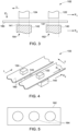
- Fig. 1 illustrates a non-limiting example of a configuration of an automatic layup system 100.
- the automatic layup system 100 includes a stacking assembly 120 located in a first plane 'X 1 ' and a layup tool 140 located in a second plane 'X 2 ' parallel to the first plane 'X 1 ' when the automatic layup system 100 is at resting state.
- the layup tool 140 is movable in the second plane 'X 2 ' to at least one position 150 aligned with the stacking assembly 120. As illustrated, the layup tool 140 is located at a position 150 in the second plane 'X 2 ' aligned with the stacking assembly 120.
- the layup tool 140 is rotatable about a vertical axis 's' perpendicular to the first plane X 1 and the second plane 'X 2 .' The layup tool 140 has a molding surface 141.
- the stacking assembly 120 is movable along the vertical axis 's' in a direction indicated by 'z' towards the layup tool 140.
- the layup tool 140 may be movable along the vertical axis 's' in a direction opposite to the direction 'z' towards the stacking assembly 120.
- the automatic layup systems 101, 102, and 103 include two stacking assemblies 122 and 124.
- the stacking assemblies 122 and 124 may be configured to separate composite plies of same or different shapes, sizes, or shapes and sizes, and/or apply different compressive forces on composite plies.
- Reference numerals that are common to the automatic layup systems 100, 101, 102, and 103 of Figures 1-4 represent similar or identical elements.
- the stacking assemblies 122 and 124 are located in a first plane 'X 1 ' when the automatic layup systems 101, 102, and 103 are in resting state.
- the stacking assemblies 122 and 124 may be movable in the direction 'z' in an operating state of the automatic layup systems 101, 102, and 103. As illustrated in Figures 2-3 , the stacking assemblies 122 and 124 are arranged in one row along a longitudinal direction 'L' in the automatic layup systems 101 and 102. In some other embodiments, the stacking assemblies 122 and 124 may be arranged in any desired manner in the first plane 'X 1 ', for example, in parallel rows along the longitudinal direction 'L' as shown in Fig. 4. Fig. 4 shows a top view of the automatic layup system 103 having the two stacking assemblies 122 and 124 arranged in two different rows in the first plane 'X 1 .'
- the automatic layup systems 101, 102 or 103 may include a single or multiple layup tools 140 and 142.
- the automatic layup system 101 includes a single layup tool 140.
- the layup tool 140 has a molding surface 141.
- the layup tool 140 is movable in the second plane 'X 2 ' to the positions 152 and 154 aligned with the corresponding stacking assemblies 122 and 124.
- the automatic layup system 102 or 103 as shown in Figures 3 or 4 includes two layup tools 140 and 142.
- the automatic layup systems 101, 102 or 103 may include any number of stacking assemblies and any number of layup tools as per manufacturing suitability and requirement.
- Each stacking assembly 120, 122, 124 as shown in one or more of Figures 1-4 includes at least a positioning tool (not shown in Figures) that is configured to place a composite ply on the layup tool(s) 140 and/or 142 or a previously placed composite ply on the layup tool(s) 140 and/or 142.
- the positioning tool is configured to separate a composite ply from one or more composite sheets prior to or during placing the composite ply on the layup tool(s) 140/142 or a previously placed composite ply on the layup tool(s).
- the positioning tool is a stamping tool.
- each stacking assembly 120, 122, 124 further includes a separating tool that is configured to separate a composite ply from one or more composite sheets.
- the separating tool is a cutting tool.
- the stacking assemblies 122 and 124 may be configured to separate composite plies of same or different shapes, sizes, or shapes and sizes, as desired.
- each stacking assembly 120, 122, 124 includes a forming tool that is configured to apply a compressive force to a composite ply.
- the stacking assemblies 122 and 124 may include forming tools configured to apply different compressive force on composite plies.
- each stacking assembly 120, 122, 124 includes a separating tool, a positioning tool and a forming tool.
- each stacking assembly 120, 122, 124 may include a heating element (not shown in Figures) for heating a composite ply.
- each stacking assembly 120, 122, 124 may include an integrated positioning tool that further includes one or more of the separating tool, the forming tool or the heating tool integrated with the positioning tool.
- the automatic layup systems 100, 101, 102, and 103 includes a support structure 160 configured to hold one or more composite sheets between the corresponding stacking assembly 120 or the stacking assemblies 122, 124 and the single or two layup tools 140.
- the support structure 160 includes a planar surface 162 having one or more openings 164 as shown in Fig. 5 .
- the stacking assembly 120 may move towards the layup tool 140 through the one or more openings 164 of the planar surface 162 ( Fig. 5 ) to place a composite ply on the layup tool 140.
- the movement of various elements of the automatic layup system such as stacking assemblies, layup tool(s) and the support structure may be activated by a mechanical system or a controller such as a computing unit.
- a mechanical system or a controller such as a computing unit.
- the movement of the stacking assembly/assemblies and the layup tool(s) can be activated by designed machines or robotic systems.
- the supply of the one or more composite sheets to the automatic layup system may also be activated or controlled by a mechanical system or controller.
- a method for making a stack of a plurality of composite plies is described.
- the method for making the stack of the plurality of composite plies is performed using an automatic layup system.
- the automatic layup system includes a layup tool and a stacking assembly.
- the stacking assembly is located in a first plane of the automatic layup system and the layup tool is located in a second plane parallel to the first plane.
- the stacking assembly and the layup tool are movable towards each other.
- the method includes the step (a) of providing one or more composite sheets between the layup tool and the stacking assembly of the automatic layup system.
- providing the one or more composite sheets includes supplying the one or more composite sheets using a support structure.
- the method includes the step (b) of generating a first composite ply from the one or more composite sheets by the stacking assembly.
- the generating step (b) includes separating the first composite ply from the one or more composite sheets by the stacking assembly.
- the method further includes the step (c) of placing the first composite ply on the layup tool by the stacking assembly by bringing the stacking assembly and the layup tool close to each other.
- the step of generating the first composite ply may be performed prior to or during placing the first composite ply on the layup tool.
- the method further includes the step (d) of repeating the steps (b) and (c) for generating a second composite ply from the one or more composite sheets and placing the second composite ply on the first composite ply placed on the layup tool.
- the placing of the first composite ply and the second composite ply may be performed by the stacking assembly using at least a positioning tool.
- the steps of generating the first composite ply and the second composite ply may be performed by the stacking assembly using, for example, a separating tool.
- the method includes compressing (for example, compacting or pushing) the first or the second composite ply while generating and placing the corresponding composite ply on the layup tool or the previously placed composite ply.
- the method includes stamping the first composite ply or the second composite ply on the layup tool or the previously placed composite ply on the layup tool. This compressing of a composite ply while generating and placing the corresponding composite ply can be performed by a tool, for example, a stamping tool integrated with the positioning tool or the positioning tool having a shape suitable for the desired purpose.
- the method includes repeating the steps (b) and (c) multiple times after the step (d) with a third, fourth and n th composite ply for generating and placing the third, fourth and n th composite ply on a previously placed composite ply on the layup tool to make the stack of the plurality of composite plies.
- the method includes repeating the steps (b) and (c) for generating a third composite ply from the one or more composite sheets and placing the third composite ply on the second composite ply.
- the method may further include repeating the steps (b) and (c) for generating a fourth composite ply from the one or more composite sheets and placing the fourth composite ply on the third composite ply.
- the method includes generating the third, fourth and n th composite ply prior to or during the corresponding steps of placing the third, fourth and n th composite ply on the previously placed composite ply on the layup tool.
- a value of 'n' may be at least 5. Depending on various parameters, for example thickness of the composite plies and various end use applications, the value of 'n' may range from 5 to about 10000. In some embodiments, the value of 'n' is in a range from about 10 to about 1000.
- the method includes rotating the layup tool about the vertical axis 's' to attain a desired position in the second plane prior to place a composite ply on the layup tool or a subsequent composite ply on the previously placed composite ply. This rotation of the layup tool allows to place the subsequent composite ply in a desired orientation with respect to the previously placed composite ply on the layup tool.
- the method includes the steps of applying a first compressive force on the first composite ply after or during placing the first composite ply on the layup tool and prior to the step (d).
- the step of applying the first compressive force on the first composite ply may be performed prior to placing the second composite ply on the first composite ply. This application of the first compressive force may be performed by the stacking assembly using a forming tool.
- the placing and the applying the first compressive force on the first composite ply may be performed sequentially or simultaneously.
- the method may include the steps of applying a second, third, fourth and n th compressive force on the corresponding second, third, fourth and n th composite ply after or during placing the corresponding composite ply on the previously placed composite ply and prior to placing the subsequent composite ply on the corresponding composite ply.
- the first, second, third, fourth and n th compressive force may be different depending on desired pressure to be applied on the number of composite plies placed below the corresponding first, second, third, fourth and n th composite ply in the stack.
- the method includes the step of applying a compressive force on the stack of the plurality of composite plies placed on the layup tool to form a composite structure.
- the compressive force may be applied using for example, a membrane, bladder, roller or die forming.
- Application of a compressive force to the one or more composite plies or the stack of the plurality of composite plies helps to adhere the one or more composite plies or the stack of the plurality of composite plies without wrinkles to the previously placed composite ply on the layup tool or the layup tool.
- the method of making the stack of the plurality of composite plies includes the steps of applying a first, second, third and n th compressive force on the corresponding first, second, third and n th composite ply after or during placing the corresponding composite ply on the previously placed composite ply and prior to placing the subsequent composite ply on the corresponding composite ply, the resulting stack of the plurality of composite plies forms a composite structure.
- the method includes the step of applying the compressive force on the stack of the plurality of composite plies placed on the layup tool, a composite structure is formed after applying the compressive force on the stack of the plurality of composite plies.
- Figures 6(a)-6(g) schematically represent one embodiment of the method according to the claimed invention for making a stack of a plurality of composite plies using the automatic layup system 100 as shown in Fig. 1 .
- Fig. 6(a) illustrates the step of providing a first composite ply 200 generated from one or more composite sheets provided between the layup tool 140 and the stacking assembly 120 of the automatic layup system 100.
- the one or more composite sheets may be supplied using the support structure 160 between the layup tool 140 and the stacking assembly 120.
- the method includes placing the first composite ply 200 on the layup tool 140 by the stacking assembly 120.
- the placing is performed by moving the stacking assembly 120 to the layup tool 140 or in some cases, by moving the layup tool 140 towards the stacking assembly.
- the method includes moving the stacking assembly 120 to the layup tool 140 through the support structure 160 (for example, through an opening 164 of the planar surface 162 as shown in Fig. 5 ), and placing the first composite ply 200 on the molding surface 141 of the layup tool 140.
- the method includes moving the stacking assembly 120 in an opposite direction of the direction 'z' to attain its previous position as shown in Fig. 6(d) .
- the method further includes repeating the steps 6(a) and 6(b) with a second composite ply 202 for placing the second composite ply 202 on the first composite ply 200 placed on the layup tool 140 as shown in Figures 6(e)-6(g) .
- the method includes providing the second composite ply 202 between the stacking assembly 120 and the layup tool 140 as shown in Fig. 6(e) similar to the method step as shown in Fig. 6(a) for providing the first composite ply 200.
- the second composite ply 202 is generated from the one or more composite sheets provided between the stacking assembly 120 and the layup tool 140.
- the method includes placing the second composite ply 202 by the stacking assembly 120 on the first composite ply 200 placed on the layup tool 140.
- the method includes moving the stacking assembly 120 to the layup tool 140 similar to the step as shown in Fig. 6(b)-6(c) and placing the second composite ply 202 on the previously placed first composite ply 200 on the layup tool 140 to form a stack 210 of the first and second composite plies 200 and 202.
- the method 10 includes moving the stacking assembly 120 in an opposite direction of the direction 'z' to attain its previous position as shown in Fig. 6(h) .
- the first composite ply 200 and the second composite ply 202 may be same or different in material, orientation, or both.
- the method includes repeating the steps as shown in Figures 6(e)-6(h) with a third, fourth and n th composite ply for placing the third, fourth and n th composite ply on the previously placed composite ply on the layup tool 140 to make a stack of a plurality of composite plies.
- the plurality of composite plies may be same or different in material, orientation, or both.
- the step of providing the first composite ply 200 may include generating the first composite ply 200 from one or more composite sheets prior to or during the steps 6(a)-6(c) of placing the first composite ply 200.
- the method includes separating the first composite ply 200 from the one or more composite sheets by the stacking assembly 120, for example using a stamping tool or a separating tool (as described previously) of the stacking assembly 120.
- the method includes separating the first composite ply 200 from the one or more composite sheets while moving the stacking assembly 120 to the layup tool 140 through the support structure 160 (for example, through an opening 164 of the substantially planar surface 162), and placing the first composite ply 200 on the layup tool 140.
- the step of providing the second composite ply 202 may include generating the second composite ply 202 from one or more composite sheets prior to or during the steps 6(e)-6(g) of placing the second composite ply 202.
- the method 10 may include separating the second composite ply 202 from the one or more composite sheets by the stacking assembly 120 while moving the stacking assembly 120 to the layup tool 140 through the support structure 160 (for example, through an opening 164 of the substantially planar surface 162), and placing the second composite ply 202 on the first composite ply 200 placed on the layup tool 140.
- the method may further include generating a subsequent composite ply from the one or more composite sheets prior to or during the step of placing the subsequent composite ply on the previously placed composite ply.
- the method includes separating the third, fourth and n th composite ply from the one or more composite sheets prior to or during the corresponding steps of placing the third, fourth and n th composite ply on the previously placed composite ply.
- an alternative method for making a stack of a plurality of composite plies is described.
- the method for making the stack of the plurality of composite plies is performed using an automatic layup system that includes a layup tool and a plurality of stacking assemblies.
- the plurality of stacking assemblies are located in a first plane and the layup tool is movable in a second plane parallel to the first plane to a plurality of positions aligned with the plurality of stacking assemblies.
- Each stacking assembly of the plurality of stacking assemblies and the layup tool are movable towards each other in an operating state of the automatic layup system.
- each stacking assembly of the plurality of stacking assemblies includes a separating tool and a positioning tool.
- each stacking assembly further includes a forming tool as described herein.
- the plurality of stacking assemblies may be configured to separate the composite plies of same or different shapes, sizes, or shapes or sizes from one or more composite sheets.
- each composite ply of the stack of the plurality of composite plies may be different in material, shape, size, orientation or combinations thereof.
- the method includes the step (i) of providing one or more composite sheets between the layup tool and the plurality of stacking assemblies.
- providing the one or more composite sheets includes supplying the one or more composite sheets using a support structure.
- the one or more composite sheets may be same or different in their materials, structures (e.g., fiber orientation) or both.
- one composite sheet is supplied between the layup tool and each stacking assembly of the plurality of stacking assemblies.
- the method includes the step (ii) of separating a first composite ply from the one or more composite sheets and placing the first composite ply on the layup tool by a first stacking assembly of the plurality of stacking assemblies.
- This separating and placing the first composite ply are performed by bringing the first stacking assembly and the layup tool close to each other when the layup tool is at a first position of the plurality of positions aligned with the first stacking assembly.
- the step of separating the first composite ply may be performed prior to or during the step of placing the first composite ply on the layup tool.
- the method further includes the step (iii) of moving the layup tool with the first composite ply to a second position of the plurality of the positions aligned with a second stacking assembly of the plurality of stacking assemblies.
- the method includes the step (iv) of separating a second composite ply from the one or more composite sheets and placing the second composite ply on the first composite ply placed on the layup tool by the second stacking assembly.
- the separating and placing the second composite ply are performed by bringing the second stacking assembly and the layup tool close to each other with the first composite ply placed on the layup tool.
- the step of separating the second composite ply may be performed prior to or during the step of placing the second composite ply on the first composite ply placed on the layup tool.
- the method further includes repeating steps (iii) and (iv) multiple times to place a third, fourth and n th composite ply on a previously placed composite ply on the layup tool when the layup tool is at a third, fourth and n th positon of the plurality of positions aligned with the third, fourth and n th stacking assembly of the plurality of stacking assemblies to make the stack of the plurality of composite plies.
- a value of 'n' may be at least 5. Depending on various parameters, for example thickness of the composite plies and various end use applications, the value of 'n' may range from 5 to about 10000. In some embodiments, the value of 'n' is in a range from about 10 to about 1000.
- the method includes rotating the layup tool about the vertical axis to attain a desired position (for example, a desired orientation) after moving the layup tool to a position aligned with a stacking assembly of the plurality of stacking assemblies and prior to placing a composite ply on the layup tool or placing a subsequent composite ply on the previously placed composite ply on the layup tool.
- a desired position for example, a desired orientation
- This rotation of the layup tool allows to place the subsequent composite ply in a desired orientation with respect to the previously placed composite ply on the layup tool.
- the method further includes applying a first compressive force on the first composite ply after the step (ii) and prior to the step (iv) and applying a second compressive force on the second composite ply after the step (iv).
- the application of the first compressive force on the first composite ply may be performed after or during placing the first composite ply.
- the application of the first compressive force on the first composite ply may be performed prior to placing the second composite ply on the first composite ply.
- the application of the second compressive force on the second composite ply may be performed after or during placing the second composite ply on the first composite ply.
- the application of the second compressive force on the second composite ply is performed prior to placing a third composite ply on the second composite ply.
- the method includes applying a third, fourth and n th compressive force on the corresponding third, fourth and n th composite ply independently after or during placing the corresponding third, fourth and n th composite ply on the previously placed composite ply on the layup tool.
- the application of the third, fourth and n th compressive force on the corresponding third, fourth and n th composite ply is performed prior to placing the subsequent composite ply on the previously place composite ply on the layup tool.
- Figures 7(a)-7(h) schematically represent one embodiment of a method for making a stack of a plurality of composite plies using the automatic layup system 101 as shown in Fig. 2 .
- a layup tool 140 is located at a first position 152 in a second plane 'X 2 ' aligned with a first stacking assembly 122.
- the method includes providing a composite sheet 250 between the stacking assemblies 122, 124 and the layup tool 140.
- the method includes supplying the composite sheet 250 using the support structure 160.
- the method includes supplying the composite sheet 250 between the stacking assembly 122, 124 and the layup tool 140 along the longitudinal direction 'L.
- the method includes supplying the composite sheet 250 between the stacking assembly 122 and the layup tool 140 in the transverse direction 'T.'
- the method includes separating a first composite ply 252 from the composite sheet 250 and placing the first composite ply 252 on the molding surface 141 of the layup tool 140.
- the separating and placing the first composite ply 252 is performed by the first stacking assembly 122 as shown in Figures 7(b)-7(c) by moving the first stacking assembly 122 to the layup tool 140.
- the method includes moving the first stacking assembly 122 in the reverse direction of the direction 'z' to its previous position as shown in Fig. 7(d) .
- the method includes moving the layup tool 140 to a second position 154 in the second plane 'X 2 ' aligned with the second stacking assembly 124 as shown in Fig. 7 (e) .
- the method includes providing the composite sheet 250 or another composite sheet 260 between the stacking assembly 124 and the layup tool 140 as shown in Fig. 7 (e) .
- the method may include continue supplying the composite sheet 250 between the stacking assembly 124 and the layup tool 140.
- the method may include supplying another composite sheet 260 between the stacking assembly 124 and the layup tool 140.
- the method includes applying a first compressive force on the first composite ply 252 by the first stacking assemblies 122 for example, by the forming tool of the stacking assemblies 122 after or during placing the first composite plies 252 on the layup tool 140 as shown in Fig. 7(c) .
- the method further includes applying a second compressive force on the second composite ply 254 or 262 by the second stacking assembly 124 after or during placing the second composite ply 254 or 262 on the first composite ply 250 placed on the layup tool 140 as shown in Fig 7(g) .
- the resulting stack 300 formed may be a composite structure.
- the method includes applying a compressive force on the stack of the first composite ply 252 and the second composite ply 254 or 262 to form a composite structure.
- the method includes moving another layup tool 140 at the first position 152 aligned with the first stacking assembly 122 as shown in Fig. 7(i) , after moving the layup tool 140 to the second position in the second plane 'X 2 '.
- the method includes repeating the steps as shown in Figures 7(a)-7(d) for placing another set of the first composite ply 252 on another layup tool 144 and the second composite ply 254 or 262 for forming another stack of the first composite ply 252 and the second composite ply 254 or 262 while continuing the desired steps for forming the stack 300 on the layup tool 140 and moving the layup tool 140 to a subsequent position in the second plane 'X 2 .
- the methods and features of methods are described in view of Figures 1, 2 and 3 for simplicity, the methods and features of the methods described herein are applicable to the automatic layup system 103 of Fig. 4 . Further, the methods include providing any number of layup tools to the automatic layup systems 100, 101, 102, and 103 as shown in Figures 1-4 to form several stacks for manufacturing desired number of composite structures. In this way, the method provides a cost-effective method for forming composite structures for production purposes.
- the present methods and systems may allow to automatically place the composite plies while avoiding picking the composite plies from one location (from example, from a cutting apparatus) and placing at another location (for example, a stamping or forming apparatus) to form a stack of composite plies.
- the methods and systems of the present disclosure may include automatically performing separating, placing and forming steps in a single apparatus for placing the composite plies on a layup tool to form a stack of a plurality of composite plies.
- the method as described herein allows forming a stack of a plurality of composite plies including composite plies that are different in material, fiber orientation, shape, size or combinations thereof as desired to form a composite structure.
Landscapes
- Engineering & Computer Science (AREA)
- Chemical & Material Sciences (AREA)
- Composite Materials (AREA)
- Mechanical Engineering (AREA)
- Robotics (AREA)
- Moulding By Coating Moulds (AREA)
- Casting Or Compression Moulding Of Plastics Or The Like (AREA)
Claims (5)
- Verfahren zum Herstellen eines Stapels aus einer Vielzahl von Verbundlagen, umfassend:a) Bereitstellen einer oder mehrerer Verbundplatten zwischen einem Layup-Werkzeug (140) und einer Stapelanordnung (120) eines automatischen Layup-Systems (100), wobei sich die Stapelanordnung (120) in einer ersten Ebene (X1) des automatischen Layup-Systems (100) befindet und sich das Layup-Werkzeug (140) in einer zweiten Ebene (X2) parallel zu der ersten Ebene (X1) befindet, und wobei die Stapelanordnung (120) und das Layup-Werkzeug (140) aufeinander zu bewegbar sind;b) Erzeugen einer ersten Verbundlage (200) aus der einen oder den mehreren Verbundplatten;c) Platzieren der ersten Verbundlage (200) auf dem Layup-Werkzeug (140) durch die Stapelanordnung (120), indem die Stapelanordnung (120) und das Layup-Werkzeug (140) einander angenähert werden; undd) Wiederholen der Schritte b) und c) zum Erzeugen einer zweiten Verbundlage (202) und Platzieren der zweiten Verbundlage (202) auf der auf dem Layup-Werkzeug (140) platzierten ersten Verbundlage (200);dadurch gekennzeichnet, dassder Schritt a) des Bereitstellens der einen oder der mehreren Verbundplatten das Zuführen der einen oder der mehreren Verbundplatten unter Verwendung einer Trägerstruktur (160) einschließt,wobei die Trägerstruktur (160) konfiguriert ist, um die eine oder die mehreren Verbundplatten zwischen der mindestens einen Stapelanordnung (120) und dem mindestens einen Layup-Werkzeug (140) zu halten, wobei die Trägerstruktur (160) eine ebene Oberfläche (162) oder einen Rahmen einschließt, der die Verbundlage oder die Verbundplatte trägt, wobei die ebene Oberfläche (162) eine oder mehrere Öffnungen (164) aufweist, die es der mindestens einen Stapelanordnung oder dem mindestens einen Layup-Werkzeug ermöglichen, sich durch die eine oder die mehreren Öffnungen (164) aufeinander zu zu bewegen.
- Verfahren nach Anspruch 1, ferner umfassend das mehrmalige Wiederholen des Schrittes d) zum Erzeugen einer dritten, vierten und n-ten Verbundlage aus der einen oder den mehreren Verbundplatten und Platzieren der dritten, vierten und n-ten Verbundlage auf einer zuvor auf dem Layup-Werkzeug (140) platzierten Verbundlage.
- Verfahren nach Anspruch 1 oder Anspruch 2, wobei der Erzeugungsschritt das Trennen der ersten Verbundlage (200) von der einen oder den mehreren Verbundplatten durch die Stapelanordnung (120) umfasst.
- Verfahren nach einem der vorstehenden Ansprüche, ferner umfassend das Ausüben einer ersten Druckkraft auf die erste Verbundlage (200) nach oder während des Platzierens der ersten Verbundlage (200) auf dem Layup-Werkzeug (140) und vor Schritt d); und Ausüben einer zweiten Druckkraft auf die zweite Verbundlage (202) nach oder während des Platzierens der zweiten Verbundlage (202) auf der ersten Verbundlage (200).
- Verfahren nach einem der vorstehenden Ansprüche, ferner umfassend das Ausüben einer Druckkraft auf den Stapel der Vielzahl von Verbundlagen zum Bilden einer Verbundstruktur.
Applications Claiming Priority (2)
| Application Number | Priority Date | Filing Date | Title |
|---|---|---|---|
| US15/361,529 US10583617B2 (en) | 2016-11-28 | 2016-11-28 | Automatic systems and methods for stacking composite plies |
| PCT/US2017/058193 WO2018097922A1 (en) | 2016-11-28 | 2017-10-25 | Automatic systems and methods for stacking composite plies |
Publications (3)
| Publication Number | Publication Date |
|---|---|
| EP3544795A1 EP3544795A1 (de) | 2019-10-02 |
| EP3544795A4 EP3544795A4 (de) | 2020-12-02 |
| EP3544795B1 true EP3544795B1 (de) | 2025-04-23 |
Family
ID=62193017
Family Applications (1)
| Application Number | Title | Priority Date | Filing Date |
|---|---|---|---|
| EP17875002.2A Active EP3544795B1 (de) | 2016-11-28 | 2017-10-25 | Verfahren zum stapeln von verbundlagen |
Country Status (4)
| Country | Link |
|---|---|
| US (1) | US10583617B2 (de) |
| EP (1) | EP3544795B1 (de) |
| CN (1) | CN110198829A (de) |
| WO (1) | WO2018097922A1 (de) |
Family Cites Families (98)
| Publication number | Priority date | Publication date | Assignee | Title |
|---|---|---|---|---|
| CA928924A (en) | 1969-02-20 | 1973-06-26 | E. Bugel Thomas | Stamping blank of glass and thermoplastic resin |
| US3621092A (en) | 1969-02-20 | 1971-11-16 | Union Carbide Corp | Stamping process |
| CA1013114A (en) | 1970-03-25 | 1977-07-05 | Anthony M. Fazzari | Glass reinforced composites with improved surface and process |
| FR2238585A1 (en) | 1973-07-26 | 1975-02-21 | Peugeot & Renault | Composite material shaped by stamping - comprises glass fibre layer between metal sheets spot welded together |
| DE2365895A1 (de) | 1973-12-21 | 1977-05-12 | Kiss Consulting Eng | Verfahren und anlage zur herstellung von formkoerpern aus einer fasermatte |
| JPS5144166A (ja) | 1974-10-11 | 1976-04-15 | Fukubi Kagaku Kogyo Kk | Goseijushisoshokuzaino renzokuoshidashiseikeihoho |
| JPS5374175A (en) | 1976-12-15 | 1978-07-01 | Ishizuka Glass | Method and apparatus for making fiber molded article |
| CA1137724A (en) | 1977-07-18 | 1982-12-21 | Michael P. Dellavecchia | Fiber reinforced multi-ply stampable thermoplastic sheet |
| JPS55164127A (en) | 1979-06-08 | 1980-12-20 | Asahi Glass Co Ltd | Stamp-molding method |
| JPS565734A (en) | 1979-06-29 | 1981-01-21 | Asahi Glass Co Ltd | Molding method of stamp |
| JPS5729490A (en) | 1980-07-30 | 1982-02-17 | Sanko Gouseijiyushi Kogyo Kk | Hot stamping method to synthetic resin product |
| JPS5747619A (en) | 1980-09-05 | 1982-03-18 | Asahi Glass Co Ltd | Stamping method |
| JPS5782013A (en) | 1980-11-11 | 1982-05-22 | Showa Denko Kk | Solid phase stamping molding method of thermoplastic synthetic resin sheet |
| JPS6050146B2 (ja) | 1981-01-21 | 1985-11-07 | 東レ株式会社 | スタンピング成形用シ−ト |
| JPS57201650A (en) | 1981-06-05 | 1982-12-10 | Asahi Glass Co Ltd | Stamp molding material and its manufacture |
| JPS58116130A (ja) | 1981-12-30 | 1983-07-11 | Hosei Brake Kogyo Kk | 熱可塑性樹脂複合材シ−トのスタンピング成形方法 |
| JPS5971847A (ja) | 1982-10-19 | 1984-04-23 | 宇部興産株式会社 | スタンピング成形シ−ト |
| US4622192A (en) | 1984-01-10 | 1986-11-11 | Phillips Petroleum Company | Stampable sheets of glass/carbon fiber mat reinforced polymers of olefin and method of preparation |
| FR2567807A1 (fr) | 1984-07-20 | 1986-01-24 | Bronzavia Sa | Procede pour la realisation de pieces en materiaux composites et dispositif pour la mise en oeuvre de ce procede et pieces obtenues par ce procede |
| JPS6140122A (ja) | 1984-08-01 | 1986-02-26 | Teijin Ltd | ポリエステル樹脂成形品の製造方法 |
| JPS61248724A (ja) | 1985-04-25 | 1986-11-06 | Mazda Motor Corp | 熱可塑性樹脂シ−トのスタンピング成形方法 |
| JPS6256115A (ja) | 1985-09-05 | 1987-03-11 | Mazda Motor Corp | 熱可塑性樹脂シ−トのスタンピング成形方法 |
| JPS62161522A (ja) | 1986-01-10 | 1987-07-17 | Asano Kenkyusho:Kk | シ−トスタンピング成形法の改良 |
| JPS62179909A (ja) | 1986-02-05 | 1987-08-07 | Mazda Motor Corp | 繊維強化プラスチツクシ−トのスタンピング成形方法 |
| US5200133A (en) | 1986-09-17 | 1993-04-06 | Bronzavia-Air Equipment | Method for making composite material parts by stamping |
| JPS6387228A (ja) | 1986-10-01 | 1988-04-18 | 株式会社トクヤマ | 複合体の製造方法 |
| JPH01235614A (ja) | 1988-03-17 | 1989-09-20 | Kojima Press Co Ltd | 表皮を有する複合成形体の成形方法 |
| US5260017A (en) | 1990-01-02 | 1993-11-09 | General Electric Company | Method for improved surface profile of composite structures |
| US5049323A (en) | 1990-03-26 | 1991-09-17 | General Electric Company | Method for thermostamping thermoplastic composites |
| JP2948903B2 (ja) | 1990-11-30 | 1999-09-13 | 昭和電工株式会社 | ガラス繊維強化樹脂成形品の製造法 |
| JPH059301A (ja) | 1990-12-17 | 1993-01-19 | Nippon Steel Corp | スタンピング成形材料およびスタンピング成形品 |
| JP3053885B2 (ja) | 1991-02-20 | 2000-06-19 | 株式会社林技術研究所 | スタンピング成形方法 |
| JPH0524058A (ja) | 1991-07-19 | 1993-02-02 | Bridgestone Corp | 繊維強化熱可塑性樹脂加飾成形板の製造方法 |
| US5247825A (en) | 1991-10-31 | 1993-09-28 | Manufacturers Products Company | Method of forming part in progressive die system |
| JPH06155495A (ja) | 1992-11-20 | 1994-06-03 | Nippon Steel Corp | 繊維強化熱可塑性樹脂スタンパブルシート製バンパービーム |
| JPH06155498A (ja) | 1992-11-20 | 1994-06-03 | Nippon Steel Corp | 繊維強化熱可塑性樹脂スタンパブルシートの成形方法 |
| JPH06155499A (ja) | 1992-11-20 | 1994-06-03 | Nippon Steel Corp | 繊維強化熱可塑性樹脂スタンパブルシートの成形方法 |
| JPH06234129A (ja) | 1993-02-08 | 1994-08-23 | Kuraray Co Ltd | 複合体の製造方法 |
| JPH06270177A (ja) | 1993-03-23 | 1994-09-27 | Kuraray Co Ltd | 複合成形品の製造方法 |
| JPH06306219A (ja) | 1993-04-21 | 1994-11-01 | Idemitsu N S G Kk | スタンピング成形用複合シート |
| JPH06344837A (ja) | 1993-06-04 | 1994-12-20 | Nippon Steel Corp | スタンパブルシート製バンパービーム |
| US5585432A (en) | 1993-10-15 | 1996-12-17 | General Electric Company | Flow formable composites having polymodal fiber distributions |
| DE59406668D1 (de) | 1993-12-02 | 1998-09-17 | Heraeus Gmbh W C | Verfahren und Vorrichtung zur Herstellung eines Folienverbundes |
| US5468437A (en) | 1994-01-18 | 1995-11-21 | General Electric Company | Process for producing stabilized non-woven thermoplastic composites |
| US5540126A (en) * | 1994-05-26 | 1996-07-30 | Piramoon Technologies | Automatic lay-up machine for composite fiber tape |
| JPH085057A (ja) | 1994-06-14 | 1996-01-12 | Mitsui Eng & Shipbuild Co Ltd | 粉体燃料の燃焼制御方法及び装置 |
| JPH0827281A (ja) | 1994-07-20 | 1996-01-30 | Kuraray Co Ltd | ガラス繊維強化複合材料 |
| JPH08267626A (ja) | 1995-03-30 | 1996-10-15 | Toray Ind Inc | 成形品 |
| JPH09300372A (ja) | 1996-05-14 | 1997-11-25 | Unitika Ltd | シートスタンピング成形品及びその製造方法 |
| US6270600B1 (en) | 1996-07-03 | 2001-08-07 | Henkel Corporation | Reinforced channel-shaped structural member methods |
| JPH1035542A (ja) | 1996-07-18 | 1998-02-10 | Ube Nitto Kasei Co Ltd | 自動車用ステップ |
| JP2976913B2 (ja) | 1997-01-13 | 1999-11-10 | 日本板硝子株式会社 | 複合長繊維強化熱可塑性樹脂スタンパブルシート及びそれを成形してなるバンパービーム |
| WO1999015323A1 (en) | 1997-09-19 | 1999-04-01 | Dow-United Technologies Composite Products, Inc. | Method for fabricating a corrugated composite channel |
| KR19990075617A (ko) | 1998-03-23 | 1999-10-15 | 윤종용 | 유량 조절 밸브 |
| JPH11291274A (ja) | 1998-04-14 | 1999-10-26 | Honda Motor Co Ltd | ギヤ、スプロケット類のスタンピング成形法 |
| GB9825999D0 (en) | 1998-11-28 | 1999-01-20 | British Aerospace | A machine for laying up fabric to produce a laminate |
| DE19924005A1 (de) | 1999-05-26 | 2000-11-30 | Karlsruhe Forschzent | Verfahren zur Herstellung von Mikrostrukturkörpern |
| DE10246851C1 (de) | 2002-10-08 | 2003-12-18 | Sgl Carbon Ag | Verfahren zur Herstellung von Bauteilen aus faserverstärkter Verbundkeramik sowie deren Verwendungen |
| ES2290419T3 (es) * | 2003-09-10 | 2008-02-16 | Grupo Antolin Ingenieria, S.A. | Una instalacion para cortar y aplicar fibras de refuerzo. |
| FR2863543B1 (fr) | 2003-12-16 | 2007-11-02 | Airbus France | Procede de formage par estampage a chaud de pieces de tolerie complexes en materiau composite et outillage pour sa mise en oeuvre |
| US8557165B2 (en) | 2008-10-25 | 2013-10-15 | The Boeing Company | Forming highly contoured composite parts |
| DE102007012607B4 (de) | 2007-03-13 | 2009-02-26 | Eads Deutschland Gmbh | Spreizvorrichtung zum Aufspreizen von Faserfilamentbündeln sowie damit versehene Preform-Herstellvorrichtung |
| DE102008012255B4 (de) | 2007-03-13 | 2017-03-16 | Airbus Defence and Space GmbH | Verfahren zum Herstellen eines textilen Halbzeugs mit kraftflussgerecht verlaufenden Faserfilamenten für eine kraftflussgerechte Faserverbundstruktur |
| DE102007012609B4 (de) | 2007-03-13 | 2010-05-12 | Eads Deutschland Gmbh | Legevorrichtung und Legestempel zur Verwendung in einer Legevorrichtung |
| GB2447964B (en) * | 2007-03-29 | 2012-07-18 | Gurit Uk Ltd | Moulding material |
| FR2922811B1 (fr) | 2007-10-31 | 2013-03-01 | Airbus France | Procede de realisation d'une piece de structure comprenant une matrice en resine thermodurcissable. |
| EP2226186A1 (de) * | 2009-03-06 | 2010-09-08 | Lm Glasfiber A/S | Verfahren und Produktionslinie zur Herstellung von Windturbinenblättern |
| JP2011241450A (ja) | 2010-05-19 | 2011-12-01 | Keijiro Yamamoto | 積層造形方法及び積層造形装置 |
| DE102010061991B4 (de) | 2010-11-25 | 2016-06-09 | Bayerische Motoren Werke Aktiengesellschaft | Verfahren zum Stanzen einer aus Fasermaterial bestehenden Fasermatte |
| US8808490B2 (en) * | 2011-08-04 | 2014-08-19 | The Boeing Company | Methods for laminating composites |
| US8997642B2 (en) | 2011-08-08 | 2015-04-07 | The Boeing Company | Method for transporting, placing and compacting composite stiffeners |
| JP5920775B2 (ja) | 2011-08-09 | 2016-05-18 | 一般財団法人生産技術研究奨励会 | 繊維強化複合板の成形方法 |
| CN102430642A (zh) | 2011-09-19 | 2012-05-02 | 天津市津兆机电开发有限公司 | 带高翻边孔的高温合金钣金件的级进模成型工艺 |
| CN102343680B (zh) * | 2011-09-29 | 2013-11-06 | 哈尔滨工业大学 | 纤维增强六角蜂窝结构芯材的一体化成型模具及成型方法 |
| FR2981001B1 (fr) | 2011-10-06 | 2013-11-29 | Arts | Procede de fabrication en materiau composite de pieces tridimensionnelles et/ou massives |
| FR2984191B1 (fr) | 2011-12-20 | 2014-01-10 | Michelin Soc Tech | Machine et procede pour la fabrication additive a base de poudre |
| FR2987304B1 (fr) | 2012-02-29 | 2018-03-02 | Daher Aerospace | Procede de formage par estampage d'un materiau composite thermoplastique a renfort fibreux continu |
| CN103452158A (zh) | 2012-05-30 | 2013-12-18 | 株式会社水山重工业 | 液压破碎锤的气缸液压损失防止装置 |
| US20150174797A1 (en) | 2012-07-20 | 2015-06-25 | Namba Press Works Co., Ltd. | Press molding with reinforcing rib and manufacturing method therefor |
| US8826957B2 (en) | 2012-08-31 | 2014-09-09 | General Electric Company | Methods and systems for automated ply layup for composites |
| BR112015004530A8 (pt) | 2012-09-05 | 2019-08-27 | Aprecia Pharmaceuticals Co | montagem de equipamento de impressão tridimensional e método para preparação de artigos impressos tridimensionalmente |
| JP2014069403A (ja) | 2012-09-28 | 2014-04-21 | Teijin Ltd | スタンパブルシート状物を用いたプレス成型品の製造方法 |
| FR2999465B1 (fr) | 2012-12-19 | 2015-05-29 | Compose | Station et procede de production d'une piece en matiere thermoplastique obtenue par soudure de parties de piece estampees |
| US9498915B2 (en) | 2013-01-02 | 2016-11-22 | The Boeing Company | Fabrication of reinforced thermoplastic composite parts |
| US20140238617A1 (en) | 2013-02-28 | 2014-08-28 | General Electric Company | System and method for removal of a layer |
| DE102013103039A1 (de) * | 2013-03-25 | 2014-09-25 | Dieffenbacher GmbH Maschinen- und Anlagenbau | Verfahren, Vorrichtung und Vorformling zur mehrstufigen Herstellung eines dreidimensionalen Vorformlings im Zuge der Herstellung von faserverstärkten Formteilen |
| CA2917887A1 (en) | 2013-07-09 | 2015-01-15 | Grant O. COOK | Counterfeit proofing of plated polymers |
| JP5462401B1 (ja) | 2013-08-19 | 2014-04-02 | クツワ工業株式会社 | 熱可塑性樹脂シートの表面成形方法および表面成形装置 |
| FR3012993B1 (fr) | 2013-11-09 | 2016-07-15 | Daher Aerospace | Dispositif et procede pour l’estampage d’un flan composite a matrice thermoplastique |
| FR3016314B1 (fr) | 2013-12-24 | 2016-04-15 | Daher Aerospace | Procede et dispositif pour l’estampage d’un flan composite a matrice thermoplastique non consolide |
| JP2015131394A (ja) | 2014-01-09 | 2015-07-23 | 東レ株式会社 | 繊維強化熱可塑性樹脂一体化構造体 |
| KR101627683B1 (ko) | 2015-11-23 | 2016-06-07 | 한국생산기술연구원 | 중공형상체를 조형가능한 금속 3d프린팅 장치 및 이를 이용하는 3d조형방법 |
| US10780614B2 (en) | 2016-05-24 | 2020-09-22 | General Electric Company | System and method for forming stacked materials |
| JP6805122B2 (ja) | 2017-12-26 | 2020-12-23 | 日立建機株式会社 | 運搬車両 |
| EP3508760A1 (de) | 2018-01-05 | 2019-07-10 | Yamaha Hatsudoki Kabushiki Kaisha | Fahrzeug |
| JP6929812B2 (ja) | 2018-03-15 | 2021-09-01 | キオクシア株式会社 | 半導体装置及びメモリシステム |
| JP7056602B2 (ja) | 2018-03-20 | 2022-04-19 | 株式会社デンソー | 検出装置、制御装置、および、これを用いた電動パワーステアリング装置 |
| JP2019179909A (ja) | 2018-03-30 | 2019-10-17 | 住友ベークライト株式会社 | 電磁波シールド用フィルム、および電磁波シールド用フィルム封止電子部品搭載基板 |
-
2016
- 2016-11-28 US US15/361,529 patent/US10583617B2/en active Active
-
2017
- 2017-10-25 EP EP17875002.2A patent/EP3544795B1/de active Active
- 2017-10-25 CN CN201780084388.XA patent/CN110198829A/zh active Pending
- 2017-10-25 WO PCT/US2017/058193 patent/WO2018097922A1/en not_active Ceased
Also Published As
| Publication number | Publication date |
|---|---|
| US10583617B2 (en) | 2020-03-10 |
| WO2018097922A1 (en) | 2018-05-31 |
| US20180147795A1 (en) | 2018-05-31 |
| EP3544795A4 (de) | 2020-12-02 |
| EP3544795A1 (de) | 2019-10-02 |
| CN110198829A (zh) | 2019-09-03 |
Similar Documents
| Publication | Publication Date | Title |
|---|---|---|
| CA2883361C (en) | Methods and systems for automated ply layup for composites | |
| US8029642B2 (en) | Tape removal apparatus and process | |
| JP5905082B2 (ja) | 繊維強化プラスチック成形品を製造する過程において、面状の繊維布帛から切り出した繊維輪郭を搬送する方法及び装置 | |
| CN104275807B (zh) | 短节段纤维铺放头 | |
| CN109955510B (zh) | 用于将复合板层成形到成型工具表面上的方法和设备 | |
| US20140103571A1 (en) | Method and apparatus for producing laid fibre fabrics and component preforms made of fibres | |
| JP2019048370A (ja) | 複合レイアップ構造を形成するシステムおよび方法 | |
| WO2018021226A1 (ja) | プリフォームの製造装置、及びプリフォームの製造方法 | |
| CN101426637B (zh) | 制造长复合材料片材的设备和方法 | |
| EP2511078B1 (de) | Verfahren zur Herstellung einer faserverstärkten Struktur | |
| US9321221B2 (en) | Continuous preform device for composite stringer | |
| JP6665814B2 (ja) | 成形体の製造方法 | |
| EP3544795B1 (de) | Verfahren zum stapeln von verbundlagen | |
| JP4576942B2 (ja) | プリフォームの製造方法およびプリフォームの製造装置 | |
| WO2015199033A1 (ja) | プリプレグ切断積層装置 | |
| JP6525011B2 (ja) | エアダムを形成する方法 | |
| JP4474396B2 (ja) | ゴムシート接合方法および接合装置 | |
| US20250121553A1 (en) | Pick and place end effector configured to form a kink | |
| JP2025071803A (ja) | 自動フィルム除去のシステムおよび方法 | |
| KR20230054942A (ko) | 프리폼 제조용 섬유 자동 배열 장치 | |
| JP2006088634A (ja) | Frp製角パイプの連続製造装置および連続製造方法 |
Legal Events
| Date | Code | Title | Description |
|---|---|---|---|
| STAA | Information on the status of an ep patent application or granted ep patent |
Free format text: STATUS: THE INTERNATIONAL PUBLICATION HAS BEEN MADE |
|
| PUAI | Public reference made under article 153(3) epc to a published international application that has entered the european phase |
Free format text: ORIGINAL CODE: 0009012 |
|
| STAA | Information on the status of an ep patent application or granted ep patent |
Free format text: STATUS: REQUEST FOR EXAMINATION WAS MADE |
|
| 17P | Request for examination filed |
Effective date: 20190524 |
|
| AK | Designated contracting states |
Kind code of ref document: A1 Designated state(s): AL AT BE BG CH CY CZ DE DK EE ES FI FR GB GR HR HU IE IS IT LI LT LU LV MC MK MT NL NO PL PT RO RS SE SI SK SM TR |
|
| AX | Request for extension of the european patent |
Extension state: BA ME |
|
| DAV | Request for validation of the european patent (deleted) | ||
| DAX | Request for extension of the european patent (deleted) | ||
| RIC1 | Information provided on ipc code assigned before grant |
Ipc: B29C 70/38 20060101AFI20200617BHEP Ipc: B29C 70/30 20060101ALI20200617BHEP |
|
| A4 | Supplementary search report drawn up and despatched |
Effective date: 20201029 |
|
| RIC1 | Information provided on ipc code assigned before grant |
Ipc: B29C 70/38 20060101AFI20201023BHEP Ipc: B29C 70/30 20060101ALI20201023BHEP |
|
| STAA | Information on the status of an ep patent application or granted ep patent |
Free format text: STATUS: EXAMINATION IS IN PROGRESS |
|
| 17Q | First examination report despatched |
Effective date: 20220107 |
|
| GRAP | Despatch of communication of intention to grant a patent |
Free format text: ORIGINAL CODE: EPIDOSNIGR1 |
|
| STAA | Information on the status of an ep patent application or granted ep patent |
Free format text: STATUS: GRANT OF PATENT IS INTENDED |
|
| INTG | Intention to grant announced |
Effective date: 20241118 |
|
| GRAS | Grant fee paid |
Free format text: ORIGINAL CODE: EPIDOSNIGR3 |
|
| GRAA | (expected) grant |
Free format text: ORIGINAL CODE: 0009210 |
|
| STAA | Information on the status of an ep patent application or granted ep patent |
Free format text: STATUS: THE PATENT HAS BEEN GRANTED |
|
| AK | Designated contracting states |
Kind code of ref document: B1 Designated state(s): AL AT BE BG CH CY CZ DE DK EE ES FI FR GB GR HR HU IE IS IT LI LT LU LV MC MK MT NL NO PL PT RO RS SE SI SK SM TR |
|
| RAP3 | Party data changed (applicant data changed or rights of an application transferred) |
Owner name: GENERAL ELECTRIC COMPANY |
|
| REG | Reference to a national code |
Ref country code: GB Ref legal event code: FG4D |
|
| P01 | Opt-out of the competence of the unified patent court (upc) registered |
Free format text: CASE NUMBER: APP_14212/2025 Effective date: 20250324 |
|
| REG | Reference to a national code |
Ref country code: CH Ref legal event code: EP |
|
| REG | Reference to a national code |
Ref country code: DE Ref legal event code: R096 Ref document number: 602017089098 Country of ref document: DE |
|
| REG | Reference to a national code |
Ref country code: IE Ref legal event code: FG4D |
|
| REG | Reference to a national code |
Ref country code: NL Ref legal event code: MP Effective date: 20250423 |
|
| PG25 | Lapsed in a contracting state [announced via postgrant information from national office to epo] |
Ref country code: NL Free format text: LAPSE BECAUSE OF FAILURE TO SUBMIT A TRANSLATION OF THE DESCRIPTION OR TO PAY THE FEE WITHIN THE PRESCRIBED TIME-LIMIT Effective date: 20250423 |
|
| REG | Reference to a national code |
Ref country code: AT Ref legal event code: MK05 Ref document number: 1787403 Country of ref document: AT Kind code of ref document: T Effective date: 20250423 |
|
| PG25 | Lapsed in a contracting state [announced via postgrant information from national office to epo] |
Ref country code: FI Free format text: LAPSE BECAUSE OF FAILURE TO SUBMIT A TRANSLATION OF THE DESCRIPTION OR TO PAY THE FEE WITHIN THE PRESCRIBED TIME-LIMIT Effective date: 20250423 Ref country code: ES Free format text: LAPSE BECAUSE OF FAILURE TO SUBMIT A TRANSLATION OF THE DESCRIPTION OR TO PAY THE FEE WITHIN THE PRESCRIBED TIME-LIMIT Effective date: 20250423 Ref country code: PT Free format text: LAPSE BECAUSE OF FAILURE TO SUBMIT A TRANSLATION OF THE DESCRIPTION OR TO PAY THE FEE WITHIN THE PRESCRIBED TIME-LIMIT Effective date: 20250825 |
|
| REG | Reference to a national code |
Ref country code: LT Ref legal event code: MG9D |
|
| PG25 | Lapsed in a contracting state [announced via postgrant information from national office to epo] |
Ref country code: NO Free format text: LAPSE BECAUSE OF FAILURE TO SUBMIT A TRANSLATION OF THE DESCRIPTION OR TO PAY THE FEE WITHIN THE PRESCRIBED TIME-LIMIT Effective date: 20250723 Ref country code: GR Free format text: LAPSE BECAUSE OF FAILURE TO SUBMIT A TRANSLATION OF THE DESCRIPTION OR TO PAY THE FEE WITHIN THE PRESCRIBED TIME-LIMIT Effective date: 20250724 |
|
| PG25 | Lapsed in a contracting state [announced via postgrant information from national office to epo] |
Ref country code: PL Free format text: LAPSE BECAUSE OF FAILURE TO SUBMIT A TRANSLATION OF THE DESCRIPTION OR TO PAY THE FEE WITHIN THE PRESCRIBED TIME-LIMIT Effective date: 20250423 |
|
| PG25 | Lapsed in a contracting state [announced via postgrant information from national office to epo] |
Ref country code: BG Free format text: LAPSE BECAUSE OF FAILURE TO SUBMIT A TRANSLATION OF THE DESCRIPTION OR TO PAY THE FEE WITHIN THE PRESCRIBED TIME-LIMIT Effective date: 20250423 |
|
| PGFP | Annual fee paid to national office [announced via postgrant information from national office to epo] |
Ref country code: GB Payment date: 20250923 Year of fee payment: 9 |
|
| PG25 | Lapsed in a contracting state [announced via postgrant information from national office to epo] |
Ref country code: HR Free format text: LAPSE BECAUSE OF FAILURE TO SUBMIT A TRANSLATION OF THE DESCRIPTION OR TO PAY THE FEE WITHIN THE PRESCRIBED TIME-LIMIT Effective date: 20250423 |
|
| PG25 | Lapsed in a contracting state [announced via postgrant information from national office to epo] |
Ref country code: AT Free format text: LAPSE BECAUSE OF FAILURE TO SUBMIT A TRANSLATION OF THE DESCRIPTION OR TO PAY THE FEE WITHIN THE PRESCRIBED TIME-LIMIT Effective date: 20250423 |
|
| PGFP | Annual fee paid to national office [announced via postgrant information from national office to epo] |
Ref country code: FR Payment date: 20250924 Year of fee payment: 9 |
|
| PG25 | Lapsed in a contracting state [announced via postgrant information from national office to epo] |
Ref country code: RS Free format text: LAPSE BECAUSE OF FAILURE TO SUBMIT A TRANSLATION OF THE DESCRIPTION OR TO PAY THE FEE WITHIN THE PRESCRIBED TIME-LIMIT Effective date: 20250723 |
|
| PG25 | Lapsed in a contracting state [announced via postgrant information from national office to epo] |
Ref country code: IS Free format text: LAPSE BECAUSE OF FAILURE TO SUBMIT A TRANSLATION OF THE DESCRIPTION OR TO PAY THE FEE WITHIN THE PRESCRIBED TIME-LIMIT Effective date: 20250823 |
|
| PG25 | Lapsed in a contracting state [announced via postgrant information from national office to epo] |
Ref country code: LV Free format text: LAPSE BECAUSE OF FAILURE TO SUBMIT A TRANSLATION OF THE DESCRIPTION OR TO PAY THE FEE WITHIN THE PRESCRIBED TIME-LIMIT Effective date: 20250423 |
|
| PGFP | Annual fee paid to national office [announced via postgrant information from national office to epo] |
Ref country code: DE Payment date: 20250923 Year of fee payment: 9 |
|
| PG25 | Lapsed in a contracting state [announced via postgrant information from national office to epo] |
Ref country code: SM Free format text: LAPSE BECAUSE OF FAILURE TO SUBMIT A TRANSLATION OF THE DESCRIPTION OR TO PAY THE FEE WITHIN THE PRESCRIBED TIME-LIMIT Effective date: 20250423 Ref country code: DK Free format text: LAPSE BECAUSE OF FAILURE TO SUBMIT A TRANSLATION OF THE DESCRIPTION OR TO PAY THE FEE WITHIN THE PRESCRIBED TIME-LIMIT Effective date: 20250423 |
|
| PG25 | Lapsed in a contracting state [announced via postgrant information from national office to epo] |
Ref country code: CZ Free format text: LAPSE BECAUSE OF FAILURE TO SUBMIT A TRANSLATION OF THE DESCRIPTION OR TO PAY THE FEE WITHIN THE PRESCRIBED TIME-LIMIT Effective date: 20250423 |
|
| PG25 | Lapsed in a contracting state [announced via postgrant information from national office to epo] |
Ref country code: EE Free format text: LAPSE BECAUSE OF FAILURE TO SUBMIT A TRANSLATION OF THE DESCRIPTION OR TO PAY THE FEE WITHIN THE PRESCRIBED TIME-LIMIT Effective date: 20250423 |
|
| REG | Reference to a national code |
Ref country code: DE Ref legal event code: R097 Ref document number: 602017089098 Country of ref document: DE |
|
| PG25 | Lapsed in a contracting state [announced via postgrant information from national office to epo] |
Ref country code: RO Free format text: LAPSE BECAUSE OF FAILURE TO SUBMIT A TRANSLATION OF THE DESCRIPTION OR TO PAY THE FEE WITHIN THE PRESCRIBED TIME-LIMIT Effective date: 20250423 Ref country code: SK Free format text: LAPSE BECAUSE OF FAILURE TO SUBMIT A TRANSLATION OF THE DESCRIPTION OR TO PAY THE FEE WITHIN THE PRESCRIBED TIME-LIMIT Effective date: 20250423 |
|
| PG25 | Lapsed in a contracting state [announced via postgrant information from national office to epo] |
Ref country code: IT Free format text: LAPSE BECAUSE OF FAILURE TO SUBMIT A TRANSLATION OF THE DESCRIPTION OR TO PAY THE FEE WITHIN THE PRESCRIBED TIME-LIMIT Effective date: 20250423 |
|
| PLBE | No opposition filed within time limit |
Free format text: ORIGINAL CODE: 0009261 |
|
| STAA | Information on the status of an ep patent application or granted ep patent |
Free format text: STATUS: NO OPPOSITION FILED WITHIN TIME LIMIT |
|
| REG | Reference to a national code |
Ref country code: CH Ref legal event code: L10 Free format text: ST27 STATUS EVENT CODE: U-0-0-L10-L00 (AS PROVIDED BY THE NATIONAL OFFICE) Effective date: 20260304 |
|
| 26N | No opposition filed |
Effective date: 20260126 |