EP3548745B1 - Verfahren zum betreiben eines vakuumpumpensystems - Google Patents
Verfahren zum betreiben eines vakuumpumpensystems Download PDFInfo
- Publication number
- EP3548745B1 EP3548745B1 EP17801030.2A EP17801030A EP3548745B1 EP 3548745 B1 EP3548745 B1 EP 3548745B1 EP 17801030 A EP17801030 A EP 17801030A EP 3548745 B1 EP3548745 B1 EP 3548745B1
- Authority
- EP
- European Patent Office
- Prior art keywords
- vacuum pump
- vacuum
- operating parameter
- pumps
- opened
- Prior art date
- Legal status (The legal status is an assumption and is not a legal conclusion. Google has not performed a legal analysis and makes no representation as to the accuracy of the status listed.)
- Active
Links
Images


Classifications
-
- F—MECHANICAL ENGINEERING; LIGHTING; HEATING; WEAPONS; BLASTING
- F04—POSITIVE - DISPLACEMENT MACHINES FOR LIQUIDS; PUMPS FOR LIQUIDS OR ELASTIC FLUIDS
- F04B—POSITIVE-DISPLACEMENT MACHINES FOR LIQUIDS; PUMPS
- F04B37/00—Pumps having pertinent characteristics not provided for in, or of interest apart from, groups F04B25/00 - F04B35/00
- F04B37/10—Pumps having pertinent characteristics not provided for in, or of interest apart from, groups F04B25/00 - F04B35/00 for special use
- F04B37/14—Pumps having pertinent characteristics not provided for in, or of interest apart from, groups F04B25/00 - F04B35/00 for special use to obtain high vacuum
-
- F—MECHANICAL ENGINEERING; LIGHTING; HEATING; WEAPONS; BLASTING
- F04—POSITIVE - DISPLACEMENT MACHINES FOR LIQUIDS; PUMPS FOR LIQUIDS OR ELASTIC FLUIDS
- F04B—POSITIVE-DISPLACEMENT MACHINES FOR LIQUIDS; PUMPS
- F04B35/00—Piston pumps specially adapted for elastic fluids and characterised by the driving means to their working members, or by combination with, or adaptation to, specific driving engines or motors, not otherwise provided for
- F04B35/04—Piston pumps specially adapted for elastic fluids and characterised by the driving means to their working members, or by combination with, or adaptation to, specific driving engines or motors, not otherwise provided for the means being electric
-
- F—MECHANICAL ENGINEERING; LIGHTING; HEATING; WEAPONS; BLASTING
- F04—POSITIVE - DISPLACEMENT MACHINES FOR LIQUIDS; PUMPS FOR LIQUIDS OR ELASTIC FLUIDS
- F04B—POSITIVE-DISPLACEMENT MACHINES FOR LIQUIDS; PUMPS
- F04B49/00—Control, e.g. of pump delivery, or pump pressure of, or safety measures for, machines, pumps, or pumping installations, not otherwise provided for, or of interest apart from, groups F04B1/00 - F04B47/00
- F04B49/06—Control using electricity
- F04B49/065—Control using electricity and making use of computers
-
- F—MECHANICAL ENGINEERING; LIGHTING; HEATING; WEAPONS; BLASTING
- F04—POSITIVE - DISPLACEMENT MACHINES FOR LIQUIDS; PUMPS FOR LIQUIDS OR ELASTIC FLUIDS
- F04B—POSITIVE-DISPLACEMENT MACHINES FOR LIQUIDS; PUMPS
- F04B49/00—Control, e.g. of pump delivery, or pump pressure of, or safety measures for, machines, pumps, or pumping installations, not otherwise provided for, or of interest apart from, groups F04B1/00 - F04B47/00
- F04B49/20—Control, e.g. of pump delivery, or pump pressure of, or safety measures for, machines, pumps, or pumping installations, not otherwise provided for, or of interest apart from, groups F04B1/00 - F04B47/00 by changing the driving speed
-
- F—MECHANICAL ENGINEERING; LIGHTING; HEATING; WEAPONS; BLASTING
- F04—POSITIVE - DISPLACEMENT MACHINES FOR LIQUIDS; PUMPS FOR LIQUIDS OR ELASTIC FLUIDS
- F04C—ROTARY-PISTON, OR OSCILLATING-PISTON, POSITIVE-DISPLACEMENT MACHINES FOR LIQUIDS; ROTARY-PISTON, OR OSCILLATING-PISTON, POSITIVE-DISPLACEMENT PUMPS
- F04C25/00—Adaptations of pumps for special use of pumps for elastic fluids
- F04C25/02—Adaptations of pumps for special use of pumps for elastic fluids for producing high vacuum
-
- F—MECHANICAL ENGINEERING; LIGHTING; HEATING; WEAPONS; BLASTING
- F04—POSITIVE - DISPLACEMENT MACHINES FOR LIQUIDS; PUMPS FOR LIQUIDS OR ELASTIC FLUIDS
- F04C—ROTARY-PISTON, OR OSCILLATING-PISTON, POSITIVE-DISPLACEMENT MACHINES FOR LIQUIDS; ROTARY-PISTON, OR OSCILLATING-PISTON, POSITIVE-DISPLACEMENT PUMPS
- F04C28/00—Control of, monitoring of, or safety arrangements for, pumps or pumping installations specially adapted for elastic fluids
- F04C28/08—Control of, monitoring of, or safety arrangements for, pumps or pumping installations specially adapted for elastic fluids characterised by varying the rotational speed
-
- F—MECHANICAL ENGINEERING; LIGHTING; HEATING; WEAPONS; BLASTING
- F04—POSITIVE - DISPLACEMENT MACHINES FOR LIQUIDS; PUMPS FOR LIQUIDS OR ELASTIC FLUIDS
- F04C—ROTARY-PISTON, OR OSCILLATING-PISTON, POSITIVE-DISPLACEMENT MACHINES FOR LIQUIDS; ROTARY-PISTON, OR OSCILLATING-PISTON, POSITIVE-DISPLACEMENT PUMPS
- F04C28/00—Control of, monitoring of, or safety arrangements for, pumps or pumping installations specially adapted for elastic fluids
- F04C28/24—Control of, monitoring of, or safety arrangements for, pumps or pumping installations specially adapted for elastic fluids characterised by using valves controlling pressure or flow rate, e.g. discharge valves or unloading valves
-
- F—MECHANICAL ENGINEERING; LIGHTING; HEATING; WEAPONS; BLASTING
- F04—POSITIVE - DISPLACEMENT MACHINES FOR LIQUIDS; PUMPS FOR LIQUIDS OR ELASTIC FLUIDS
- F04B—POSITIVE-DISPLACEMENT MACHINES FOR LIQUIDS; PUMPS
- F04B2201/00—Pump parameters
- F04B2201/02—Piston parameters
- F04B2201/021—Rotational speed of a piston rotating around its own axis
-
- F—MECHANICAL ENGINEERING; LIGHTING; HEATING; WEAPONS; BLASTING
- F04—POSITIVE - DISPLACEMENT MACHINES FOR LIQUIDS; PUMPS FOR LIQUIDS OR ELASTIC FLUIDS
- F04B—POSITIVE-DISPLACEMENT MACHINES FOR LIQUIDS; PUMPS
- F04B2201/00—Pump parameters
- F04B2201/06—Valve parameters
- F04B2201/0601—Opening times
-
- F—MECHANICAL ENGINEERING; LIGHTING; HEATING; WEAPONS; BLASTING
- F04—POSITIVE - DISPLACEMENT MACHINES FOR LIQUIDS; PUMPS FOR LIQUIDS OR ELASTIC FLUIDS
- F04B—POSITIVE-DISPLACEMENT MACHINES FOR LIQUIDS; PUMPS
- F04B2201/00—Pump parameters
- F04B2201/06—Valve parameters
- F04B2201/0604—Valve noise
-
- F—MECHANICAL ENGINEERING; LIGHTING; HEATING; WEAPONS; BLASTING
- F04—POSITIVE - DISPLACEMENT MACHINES FOR LIQUIDS; PUMPS FOR LIQUIDS OR ELASTIC FLUIDS
- F04B—POSITIVE-DISPLACEMENT MACHINES FOR LIQUIDS; PUMPS
- F04B2203/00—Motor parameters
- F04B2203/02—Motor parameters of rotating electric motors
- F04B2203/0201—Current
-
- F—MECHANICAL ENGINEERING; LIGHTING; HEATING; WEAPONS; BLASTING
- F04—POSITIVE - DISPLACEMENT MACHINES FOR LIQUIDS; PUMPS FOR LIQUIDS OR ELASTIC FLUIDS
- F04B—POSITIVE-DISPLACEMENT MACHINES FOR LIQUIDS; PUMPS
- F04B2203/00—Motor parameters
- F04B2203/02—Motor parameters of rotating electric motors
- F04B2203/0209—Rotational speed
-
- F—MECHANICAL ENGINEERING; LIGHTING; HEATING; WEAPONS; BLASTING
- F04—POSITIVE - DISPLACEMENT MACHINES FOR LIQUIDS; PUMPS FOR LIQUIDS OR ELASTIC FLUIDS
- F04B—POSITIVE-DISPLACEMENT MACHINES FOR LIQUIDS; PUMPS
- F04B2203/00—Motor parameters
- F04B2203/02—Motor parameters of rotating electric motors
- F04B2203/0211—Noise
Definitions
- the invention relates to a method for operating a vacuum pump system which is used in particular to evacuate a lock chamber.
- the lock chamber is in particular connected to a processing chamber.
- the vacuum pump system can also be connected directly to the processing chamber, so that no additional lock chamber is provided.
- a processing chamber In a processing chamber, products are processed, such as coated or the like, in particular under vacuum.
- the processing chamber In order to be able to feed the products into the processing chamber in particular, the processing chamber is connected to a lock chamber.
- a vacuum pump system To evacuate the lock chamber, it is connected to a vacuum pump system.
- the vacuum pump system which usually has a plurality of vacuum pumps, has, in particular, a main pump or a booster and a backing pump. Roots pumps or screw pumps are particularly suitable as main vacuum pumps.
- the vacuum pump system has a vacuum pump device, which in particular has a plurality of vacuum pumps, and the lock chamber of a valve device.
- a control device is provided which is used in particular to control the at least one vacuum pump of the vacuum pump device.
- a method for operating a vacuum pump system for evacuating a chamber with the features of the preamble of claim 1 is from US 2014/127038 known.
- the object of the invention is to create a method for operating a vacuum pump system for evacuating a chamber, in particular a lock chamber, with which a noise reduction can be achieved with short pumping times.
- the vacuum pump system operated according to the invention has a vacuum pump device having at least one vacuum pump.
- the vacuum pump device preferably has at least two vacuum pumps, in particular those connected in series, ie a main vacuum pump or a booster and a backing pump. Roots pumps or screw pumps are particularly preferred as Bosster.
- the vacuum pump device is connected to a chamber, in particular a lock chamber, a valve device being arranged between the vacuum pump device and the chamber.
- a control device is provided which is used in particular to operate the at least one vacuum pump, the speed of the electric motor driving the at least one vacuum pump being regulated by the control device in a particularly preferred embodiment.
- At least one operating parameter is first determined by the control device in order to reduce noise while still pumping out good performance.
- This at least one operating parameter is a cyclically occurring or cyclically changing operating parameter.
- a particularly suitable operating parameter is the motor current that the electric motor draws with which the at least one vacuum pump is driven, other operating parameters are also suitable.
- the evaluation of the cyclically occurring operating parameter or the cyclically occurring changes in the course of the operating parameter is evaluated with the aid of the control device. This makes it possible to reduce the speed of at least one of the vacuum pumps of the vacuum pump device before or immediately when the valve device is opened. Due to the reduced speed of at least one of the vacuum pumps of the vacuum pump device, in particular the main vacuum pump, when the valve device is opened, a considerable noise reduction can be achieved.
- At least the speed of the main vacuum pump or the booster is reduced when it is opened, and the speed of the backing pump can also be reduced.
- the speed of the backing pump can also be reduced.
- the speed is preferably reduced to 30 Hz, in particular less than 50 Hz.
- An operating parameter that changes significantly when the valve device is opened is preferably selected as the operating parameter.
- the motor current of at least one electric motor driving the vacuum pump device is particularly suitable for this purpose. Due to the increase in pressure, the motor current rises sharply when the valve device is opened. It is possible to determine the opening of the valve device in a simple manner in the course of the current.
- the significant increase lies in particular in the increase in the current by more than five times, in particular more than ten times.
- the significant change in the operating parameter that is to say, for example, the significant increase in the motor current, takes place within a very short period of in particular less than 1 to 3 seconds.
- the inlet pressure of the vacuum pump device and / or one of the vacuum pump devices can be measured with the aid of a pressure sensor.
- the time at which the valve device is opened can also be inferred in a simple manner from the time profile of the pressure.
- a temperature profile over time can be determined with the aid of a temperature sensor.
- the temperature sensor at the outlet of one of the two pumps (gas temperature) is particularly suitable here.
- the time at which the valve device was opened can in turn be determined from the temperature profile.
- a travel path of this valve i.e. the change in valve position over time, can also be used to determine the time at which the between the lock chamber and the vacuum pump system is opened to determine arranged valve device.
- a cycle duration is determined on the basis of at least one operating parameter.
- the cycle duration is the time span between two essentially identical changes in an operating parameter.
- the cycle duration is thus the time span between two significant increases in current that occur when the valve devices are opened. This is possible because in normal applications the lock chamber is opened and closed cyclically. For example, the introduction of new products to be processed or coated into the processing chamber via the lock chamber takes place at regular intervals.
- This advantage of cyclical processing and thus of a cyclical change in an operating parameter is used according to the invention to operate the at least one vacuum pump, in particular the main vacuum pump, at low speed when the valve device is opened and to reduce noise. After the valve device has been opened, the speed of the pump can be increased again so that short pumping cycles, ie rapid reduction of the pressure in the lock chamber to the desired value, can continue to be achieved with reduced noise development.
- the cycle duration can also be determined by evaluating several operating parameters and, for example, by forming mean values and / or corresponding weightings with the aid of the control device.
- the speed of the at least one vacuum pump is reduced at least temporally, at the latest at the end of the cycle period, so that the pump speed is reduced when the valve device is opened.
- the speed can also be reduced earlier if necessary.
- a load duration is also determined on the basis of the at least one operating parameter.
- the load duration is that time span in which the lock chamber is evacuated to the defined vacuum after the valve device has been opened. This can take place, for example, when the motor current is used as an operating parameter, in that a reduction in the motor current to a previously defined limit is determined or established.
- the speed of the at least one vacuum pump can already be reduced, even if the cycle duration has not yet ended.
- This has the particular advantage that the period between the end of the load period and the end of the cycle period can be used to reduce the speed of the vacuum pump in the most energy-saving way possible. In this respect, for example, little or no braking is required.
- the electrical braking energy that is generated when the speeds are reduced is stored in an energy store or fed back into the supply network.
- an energy storage or feedback unit used instead of the braking resistor that is usually provided, which is during braking strongly heated.
- the stored energy can e.g. B. can be used again to operate or accelerate the pump. This significantly improves the energy efficiency of the pump device.
- the provision of an energy storage or A regenerative unit for storing or feeding back braking energy represents an independent invention. This is independent of the cyclical operation of the pump described above.
- the provision of energy storage or feedback units can also be useful in other processes, but is particularly advantageous in combination with the invention described above.
- This independent invention thus relates to a vacuum pump with the conventional components such as a rotor, in particular arranged in a pump housing.
- a rotor in particular arranged in a pump housing.
- several rotors or, in addition, a stator can be arranged in the housing.
- the pump has a drive device, in particular in the form of an electric motor.
- an energy storage or feedback unit is then additionally provided. Through this, the electrical energy generated during braking is stored or fed back into the supply network and can be used to drive the pump or for other components.
- the energy storage or feedback unit is therefore connected in particular to the electric motor via a frequency converter.
- the electric motor acts as a generator when the pump is braked.
- Processing for example coating of a product, takes place in a processing chamber 10 indicated schematically.
- a vacuum is generated in the processing chamber 10.
- a lock chamber 12 is connected to the processing chamber 10.
- the lock chamber 12 has a lock inlet 14 for feeding a product or the like into the lock chamber 12 and a lock outlet 16 for transferring the product or the like from the lock chamber 12 into the processing chamber 10.
- the vacuum pump system has a vacuum pump device 18.
- the vacuum pump device 18 has a main vacuum pump 20 and a backing pump 22 arranged in series behind the main vacuum pump 20 in the direction of flow.
- the main vacuum pump 20 is in particular a Roots or screw pump.
- the main vacuum pump 20 is connected to the lock chamber 12 via a pipeline 24, a valve device 26 being arranged in the pipeline 24.
- the outlet of the main vacuum pump 20 is connected to the inlet of the backing pump via a pipe 28.
- the vacuum pump system also has a control device 30.
- the control device 30 is connected to the main vacuum pump 20 and the backing pump via electrical lines 32, 34 22 connected. Via the lines 32, 34, on the one hand, an electric motor can be controlled, which drives the corresponding pump, and, on the other hand, operating parameters that are measured in or on the corresponding pump can be transmitted to the control device 30.
- the measured operating parameter is, in particular, the motor current.
- further data can be transmitted to the control device and the control device can of course also take on other control tasks.
- the control device 30 can also open or close the valve 26.
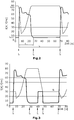
- Fig. 2 a cyclical course of a motor current and the speed of the vacuum pump according to the prior art and the Fig. 3 the corresponding graphs according to the invention.
- the curve of the motor current I represented by a thick line shows, in conventional applications, at a point in time t 1 at which the valve is opened, a sharp increase in current from I min to I max .
- the same increase in current occurs again after a cycle duration t z at a further point in time t 1 .
- the controller 30 can thus determine the cycle duration t z on the basis of the current increase occurring at cyclical intervals at the times t 1. This determination is independent of the knowledge when the valve 26 is actually opened. This is of interest insofar as no signal is often generated or output which informs the control that the valve is being opened or when it is being opened.
- the control according to the invention is self-learning in that it also can automatically determine the new cycle duration in the event of changing processes.
- the curve of the current curve represented by a thick line shows that after the current rise at time t 1, it first slowly and then falls again relatively quickly, so that at time t 2 the electric motor takes up the minimum current I min again.
- the period of time t 1 to t 2 is the load duration, ie that period of time in which the evacuation of the lock chamber 12 takes place.
- the course of the speed of the corresponding vacuum pump is shown as a thin line.
- time t 1 that is, when the valve 26 is opened, the pressure at the pump inlet increases suddenly, so that the speed of the pump falls.
- the pump speed then rises to a maximum value and then remains at this maximum speed until the next time the valve is opened at the further point in time t 1 .
- the engine speed is already reduced well before time t 1 , at which the valve 26 is opened.
- the engine speed is increased from its maximum speed at which it is during the evacuation of the lock chamber 12 a significantly lower speed.
- the time t 3 is later than a time t 2 , so that the evacuation of the lock chamber has already taken place at the time t 3 or the load duration t L has ended.
- Defined braking is again preferably carried out with the aid of the controller 30 up to a point in time t 4 .
- the current rises briefly and falls again to the minimum value at time t 4.
- the speed of the motor is therefore significantly lower than the maximum speed from time t 4.
- the motor does not have the maximum speed as in the prior art, but a significantly reduced speed.
- the kinetic energy released during braking between t 3 and t 4 can be fed back into the supply network via a feedback unit. This can increase the energy efficiency of a vacuum pump, which leads to cost savings for the operator.
- the Figure 4 shows schematically a vacuum pump 40, which is, for example, the vacuum pump 20 or 22 ( Figure 1 ) can act.
- the vacuum pump 40 has an electric motor 42 by which a pump rotor 44 is driven.
- the electric motor 42 is driven or controlled in the illustrated embodiment via a frequency converter 46.
- the frequency converter 46 is connected to the supply network 48.
- the electric motor 42 is used as a generator due to the considerable kinetic energy.
- the electrical energy produced in this way is fed via the frequency converter into an energy recovery unit 50 and can then be fed back to the supply network 48 via the lines shown.
- the connection of the frequency converter 46 to the supply network 48 via the energy recovery unit 50 is also provided.
- the energy recovery unit 50 thus simultaneously serves as a feed unit.
Landscapes
- Engineering & Computer Science (AREA)
- Mechanical Engineering (AREA)
- General Engineering & Computer Science (AREA)
- Computer Hardware Design (AREA)
- Physics & Mathematics (AREA)
- Fluid Mechanics (AREA)
- Control Of Positive-Displacement Pumps (AREA)
- Applications Or Details Of Rotary Compressors (AREA)
- Compressors, Vaccum Pumps And Other Relevant Systems (AREA)
- Control Of Fluid Pressure (AREA)
Description
- Die Erfindung betrifft ein Verfahren zum Betreiben eines Vakuumpumpensystems, das insbesondere zum Evakuieren einer Schleusenkammer dient. Die Schleusenkammer ist insbesondere mit einer Bearbeitungskammer verbunden. Ebenso kann das Vakuumpumpensystem unmittelbar mit der Bearbeitungskammer verbunden sein, so dass keine zusätzliche Schleusenkammer vorgesehen ist.
- In einer Bearbeitungskammer werden insbesondere unter Vakuum Produkte bearbeitet wie beispielsweise beschichtet oder dergleichen. Um insbesondere die Produkte der Bearbeitungskammer zuführen zu können, ist die Bearbeitungskammer mit einer Schleusenkammer verbunden. Zur Evakuierung der Scheusenkammer ist diese mit einem Vakuumpumpensystem verbunden. Das üblicherweise mehrere Vakuumpumpen aufweisende Vakuumpumpensystem weist insbesondere eine Hauptpumpe bzw. einen Booster sowie eine Vorvakuumpumpe auf. Als Hauptvakuumpumpen sind hierbei insbesondere Roots- oder Schraubenpumpen geeignet. Des Weiteren weist das Vakuumpumpensystem eine zwischen der insbesondere mehrere Vakuumpumpen aufweisenden Vakuumpumpeneinrichtung und der Schleusenkammer einer Ventileinrichtung auf. Des Weiteren ist eine Steuereinrichtung vorgesehen, die insbesondere zur Steuerung der mindestens einen Vakuumpumpe der Vakuumpumpeneinrichtung dient. Bei derartigen Schleusenanwendungen von Vakuumpumpensystemen ist eine möglichst kurze Abpumpzeit gefordert. Hierbei muss gleichzeitig sichergestellt werden, dass das zulässige Maß einer mechanischen und thermischen Belastung nicht überschritten wird. Des Weiteren besteht die Forderung, dass das Vakuumpumpensystem möglichst geräuscharm arbeitet. Die geringe Geräuschentwicklung steht jedoch im Widerspruch zu den geforderten kurzen Abpumpzeiten, da diese hohe Drehzahlen der Vakuumpumpeneinrichtung verlangen, wobei hohe Drehzahlen zu einem hohen Geräuschniveau führen.
- Ein Verfahren zum Betreiben eines Vakuumpumpen-Systems zum Evakuieren einer Kammer mit den Merkmalen des Oberbegriffs des Anspruchs 1 ist aus
US 2014/127038 bekannt. - Aufgabe der Erfindung ist, es ein Verfahren zum Betreiben eines Vakuumpumpensystems zum Evakuieren einer Kammer, insbesondere einer Schleusenkammer zu schaffen, mit dem bei geringen Abpumpzeiten eine Geräuschreduzierung erzielt werden kann.
- Die Lösung der Aufgabe erfolgt erfindungsgemäß durch ein Verfahren gemäß Anspruch 1.
- Das erfindungsgemäß betriebene Vakuumpumpensystem weist eine mindestens eine Vakuumpumpe aufweisende Vakuumpumpeneinrichtung auf. Vorzugsweise weist die Vakuumpumpeneinrichtung zumindest zwei insbesondere in Reihe geschaltete Vakuumpumpen, d.h. eine Hauptvakuumpumpe bzw. einen Booster und eine Vorvakuumpumpe auf. Als Bosster sind hierbei insbesondere Rootspumpen oder Schraubenpumpen bevorzugt. Die Vakuumpumpeneinrichtung ist mit einer Kammer, insbesondere einer Schleusenkammer verbunden, wobei zwischen der Vakuumpumpeneinrichtung und der Kammer eine Ventileinrichtung angeordnet ist. Weiterhin ist eine Steuereinrichtung vorgesehen, die insbesondere zum Betreiben der mindestens einen Vakuumpumpe dient, wobei durch die Steuereinrichtung in besonders bevorzugter Ausführungsform die Drehzahl des die mindestens eine Vakuumpumpe antreibenden Elektromotors geregelt wird.
- Zur Geräuschreduzierung bei dennoch guten Abpumpleistungen erfolgt erfindungsgemäß zunächst ein Ermitteln mindestens eines Betriebsparameters durch die Steuereinrichtung. Bei diesem mindestens einen Betriebsparameter handelt es sich um einen zyklisch auftretenden bzw. sich zyklisch verändern Betriebsparameter. Ein besonders geeigneter Betriebsparameter ist der Motorstrom, den der Elektromotor aufnimmt, mit dem die mindestens eine Vakuumpumpe angetrieben wird, wobei auch andere Betriebsparameter geeignet sind.
- Die Auswertung des zyklisch auftretenden Betriebsparameters bzw. der zyklisch auftretenden Veränderungen des Verlaufs des Betriebsparameters wird mit Hilfe der Steuereinrichtung ausgewertet. Hierdurch ist es möglich, die Drehzahl zumindest einer der Vakuumpumpen der Vakuumpumpeneinrichtung zeitlich vor oder unmittelbar beim Öffnen der Ventileinrichtung zu verringern. Aufgrund der verringerten Drehzahl zumindest einer der Vakuumpumpen der Vakuumpumpeneinrichtung, insbesondere der Hauptvakuumpumpe beim Öffnen der Ventileinrichtung kann eine erhebliche Geräuschreduzierung erzielt werden.
- Bevorzugt ist es, dass zumindest die Drehzahl der Hauptvakuumpumpe bzw. des Boosters beim Öffnen verringert ist, wobei zusätzlich auch die Drehzahl der Vorvakuumpumpe verringert werden kann. Gegenüber der im Betrieb, d.h. beim Abpumpen der Schleusenkammer auftretenden maximalen Drehzahl der Pumpe erfolgt vorzugsweise ein Verringern um mindestens 50% insbesondere mindestens 80%. Vorzugsweise wird die Drehzahl auf 30 Hz, insbesondere weniger als 50 Hz verringert.
- Als Betriebsparameter wird vorzugsweise ein sich beim Öffnen der Ventileinrichtung signifikant verändernder Betriebsparameter ausgewählt. Besonders geeignet ist hierfür der Motorstrom eines zumindest eine der Vakuumpumpeneinrichtung antreibenden Elektromotors. Aufgrund des Druckanstiegs steigt der Motorstrom beim Öffnen der Ventileinrichtung stark an. Es ist im Stromverlauf auf einfache Weise möglich das Öffnen der Ventileinrichtung zu bestimmen. Der signifikante Anstieg liegt insbesondere in der Erhöhung des Stroms um mehr als das fünffache, insbesondere mehr als das zehnfache. Insbesondere erfolgt die signifikante Änderung des Betriebsparameters, d.h. beispielsweise der signifikante Anstieg des Motorstroms innerhalb eines sehr kurzen Zeitraums von insbesondere weniger als 1 bis 3 Sekunden.
- Als Betriebsparameter ist das Ermitteln des Verlaufs des Motorstroms eines zumindest eine der Vakuumpumpen antreibenden Elektromotors bevorzugt. Alternativ oder zusätzlich können auch die folgenden Betriebsparameter bzw. der entsprechende zeitliche Verlauf dieser Betriebsparameter ermittelt und zur Steuerung der Drehzahl zumindest einer der Vakuumpumpen der Vakuumpumpeneinrichtung genutzt werden:
- Einlassdruck der Vakuumpumpeneinrichtung und/oder
- Einlassdruck zumindest einer der Vakuumpumpen der Vakuumpumpeneinrichtung und/oder
- Temperatur einer Vakuumpumpe oder eines anderen aussagekräftigen Bereichs des Vakuumpumpensystems und/oder
- Verfahrweg eines Druckentlastungsventils zwischen Einlass- und/oder Auslassseite der Hauptvakuumpumpe und/oder
- Verfahrweg eines Druckentlastungsventils zwischen Einlas- und/oder Auslassseite der Vorvakuumpumpe.
- Beispielsweise kann mit Hilfe eines Drucksensors der Einlassdruck der Vakuumpumpeneinrichtung und/oder einer der Vakuumpumpeneinrichtungen gemessen werden. Aus dem zeitlichen Verlauf des Drucks kann ebenfalls auf einfache Weise auf den Zeitpunkt geschlossen werden, zudem die Ventileinrichtung geöffnet wird.
- Alternativ oder zusätzlich kann mit Hilfe eines Temperatursensors ein zeitlicher Temperaturverlauf ermittelt werden. Geeignet ist hierbei insbesondere der Temperatursensoram Auslass einer der beiden Pumpen (Gastemperatur). Auch aus dem Temperaturverlauf lässt sich wiederum der Zeitpunkt des Öffnens der Ventileinrichtung ermitteln.
- Sofern als Haupt- oder als Vorvakuumpumpe Pumpen eingesetzt werden, die zwischen der Einlassseite und der Auslassseite ein Druckentlastungsventil aufweisen, kann auch ein Verfahrweg dieses Ventils, d.h. die zeitliche Änderung der Ventilposition genutzt werden, um den Zeitpunkt des Öffnens der zwischen der Schleusenkammer und dem Vakuumpumpensystem angeordneten Ventileinrichtung zu ermitteln.
- Erfindungsgemäß erfolgt auf Basis zumindest eines Betriebsparameters die Bestimmung einer Zyklusdauer. Die Zyklusdauer ist die Zeitspanne zwischen zwei im Wesentlichen identischen Änderungen eines Betriebsparameters. Bei der Betrachtung eines Motorstroms ist die Zyklusdauer somit die Zeitspanne zwischen zwei signifikanten Stromanstiegen, die jeweils beim Öffnen der Ventileinrichtungen auftreten. Dies ist möglich, da bei üblichen Anwendungen ein Öffnen und Schließen der Schleusenkammer zyklisch erfolgt. Beispielsweise das Einbringen neuer zu bearbeitender oder zu beschichtender Produkte über die Scheusenkammer in die Bearbeitungskammer erfolgt in regelmäßigen Abständen. Diesen Vorteil einer zyklischen Bearbeitung und somit einer zyklisch auftretenden Veränderung eines Betriebsparameters wird erfindungsgemäß genutzt, um die mindestens eine Vakuumpumpe, insbesondere die Hauptvakuumpumpe beim Öffnen der Ventileinrichtung mit geringer Drehzahl zu betreiben und die Geräuschentwicklung zu reduzieren. Nach dem Öffnen der Ventileinrichtung kann die Drehzahl der Pumpe wieder erhöht werden, so dass bei verringerter Geräuschentwicklung weiterhin kurze Abpumpzyklen, d.h. schnelles Reduzieren des Drucks in der Schleusenkammer auf den gewünschten Wert erzielt werden kann.
- Insbesondere bei der Verwendung mehrerer Betriebsparameter kann eine Bestimmung der Zyklusdauer auch durch Auswerten mehrerer Betriebsparameter und beispielsweise durch Bilden von Mittelwerten und/oder entsprechenden Gewichtungen mit Hilfe der Steuereinrichtung ermittelt werden.
- Erfindungsgemäß wird zumindest zeitlich, spätestens am Ende der Zyklusdauer die Drehzahl der mindestens einen Vakuumpumpe reduziert wird, so dass die Pumpendrehzahl beim Öffnen der Ventileinrichtung verringert ist. Je nach Art des Abpumpzyklus kann gegebenenfalls auch schon ein früheres Reduzieren der Drehzahl erfolgen.
- Bei einer besonders bevorzugten Ausführungsform erfolgt ferner anhand des zumindest einen Betriebsparameters das Ermitteln einer Lastdauer. Die Lastdauer ist hierbei diejenige Zeitspanne, in der die Schleusenkammer nach dem Öffnen der Ventileinrichtung auf das definierte Vakuum evakuiert wird. Dies kann beispielsweise bei Nutzung des Motorstroms als Betriebsparameter dadurch erfolgen, dass ein Verringern des Motorstroms auf eine zuvor festgelegte Grenze bestimmt bzw. festgestellt wird. Sobald die Lastdauer im Betrieb erreicht ist, kann die Drehzahl der mindestens einen Vakuumpumpe bereits reduziert werden, auch wenn die Zyklusdauer noch nicht beendet ist. Dies hat insbesondere den Vorteil, dass der Zeitraum zwischen dem Ende der Lastdauer und dem Ende der Zyklusdauer genutzt werden kann, um die Drehzahl der Vakuumpumpe auf möglichst energiesparende Weise zu reduzieren. Insofern ist beispielsweise kein oder ein geringfügiges Abbremsen erforderlich.
- Bei einer besonders bevorzugten Weiterbildung der Erfindung wird die elektrische Bremsenergie, die beim Reduzieren der Drehzahlen erzeugt wird, in einem Energiespeicher gespeichert oder in das Versorgungsnetz zurückgespeist. Erfindungsgemäß wird in dieser bevorzugten Ausführungsform somit anstelle des üblicherweise vorgesehenen Bremswiderstands, der sich bei Bremsvorgängen stark erwärmt, eine Energiespeicher- oder Rückspeiseeinheit eingesetzt. Die gespeicherte Energie kann z. B. zum Betreiben oder beschleunigen der Pumpe wieder genutzt werden. Hierdurch ist die Energieeffizienz der Pumpenvorrichtung deutlich verbessert. Das Vorsehen einer Energiespeicher- oder Rückspeiseeinheit zum Speichern oder Zurückspeisen von Bremsenergie stellt eine selbstständige Erfindung dar. Diese ist unabhängig von dem vorstehend beschriebenen zyklischen Betreiben der Pumpe. Das Vorsehen von Energiespeicher- oder Rückspeiseeinheiten kann auch bei anderen Prozessen zweckmäßig sein, ist jedoch in Kombination mit der vorstehend beschriebenen Erfindung besonders vorteilhaft.
- Diese selbständige Erfindung betrifft somit eine Vakuumpumpe mit den herkömmlichen Bauteilen wie einem insbesondere in einem Pumpengehäuse angeordneten Rotor. Je nach Pumpentyp können mehrere Rotoren oder zusätzlich auch ein Stator in dem Gehäuse angeordnet sein. Ferner weist die Pumpe eine Antriebseinrichtung, insbesondere in Form eines Elektromotors auf. Erfindungsgemäß ist sodann zusätzlich eine Energiespeicher- oder Rückspeiseeinheit vorgesehen. Durch diese wird die beim Bremsen erzeugte elektrische Energie gespeichert oder in das Versorgungsnetz zurückgespeist und kann zum Antreiben der Pumpe oder auch für andere Bauteile genutzt werden. Die Energiespeicher- oder Rückspeiseeinheit ist daher insbesondere mit dem Elektromotor über einen Frequenzumrichter verbunden. Der Elektromotor fungiert beim Bremsen der Pumpe als Generator.
- Nachfolgend wird die Erfindung anhand einer bevorzugten Ausführungsform unter Bezugnahme auf die Zeichnungen und Diagramme näher erläutert.
- Es zeigen:
- Fig. 1
- eine schematische Darstellung eines Vakuumpumpensystems sowie einer Schleusenkammer,
- Fig. 2
- ein Diagramm eines Motorstroms sowie einer Motordrehzahl über der Zeit bei bekannten Verfahren,
- Fig. 3
- ein Diagramm eines Motorstroms sowie einer Motordrehzahl über der Zeit nach dem erfindungsgemäßen Verfahren und
- Figuren 4 und 5
- schematische Darstellungen einer Vakuumpumpe mit einer Energierückspeiseeinheit.
- In einer schematisch angedeuteten Bearbeitungskammer 10 erfolgt ein Bearbeiten beispielsweise Beschichten eines Produkts. Hierzu ist in der Bearbeitungskammer 10 Vakuum erzeugt. Um zu bearbeitende Produkte, Material oder dergleichen in die Bearbeitungskammer zu bringen ist eine Schleusenkammer 12 mit der Bearbeitungskammer 10 verbunden. Die Schleusenkammer 12 weist einen Schleuseneinlass 14 zum Zuführen eines Produkts oder desgleichen in die Schleusenkammer 12 sowie einen Schleusenauslass 16 zum Überführen des Produkts oder desgleichen aus der Schleusenkammer 12 in die Bearbeitungskammer 10 auf.
- Zum Evakuieren der Schleusenkammer 12 ist diese mit einem Vakuumpumpensystem verbunden. Das Vakuumpumpensystem weist eine Vakuumpumpeneinrichtung 18 auf. Im dargestellten Ausführungsbeispiel weist die Vakuumpumpeneinrichtung 18 eine Hauptvakuumpumpe 20 und eine in Strömungsrichtung in Reihe hinter der Hauptvakuumpumpe 20 angeordnete Vorvakuumpumpe 22 auf. Bei der Hauptvakuumpumpe 20 handelt es sich insbesondere um eine Roots- oder Schraubenpumpe. Die Hauptvakuumpumpe 20 ist über eine Rohrleitung 24 mit der Schleusenkammer 12 verbunden, wobei in der Rohrleitung 24 eine Ventileinrichtung 26 angeordnet ist. Der Auslass der Hauptvakuumpumpe 20 ist über eine Rohrleitung 28 mit dem Einlass der Vorvakuumpumpe verbunden.
- Ferner weist das Vakuumpumpensystem eine Steuereinrichtung 30 auf. Die Steuereinrichtung 30 ist im dargestellten Ausführungsbeispiel über elektrische Leitungen 32, 34 mit der Hauptvakuumpumpe 20 sowie der Vorvakuumpumpe 22 verbunden. Über die Leitungen 32, 34 kann einerseits eine Steuerung eines Elektromotors erfolgen, der die entsprechende Pumpe antreibt und andererseits können Betriebsparameter, die in oder an der entsprechenden Pumpe gemessen werden zu Steuereinrichtung 30 übermittelt werden.
- Bei dem gemessenen Betriebsparameter handelt es sich insbesondere um den Motorstrom. Ferner können, wie durch einen Pfeil 36 dargestellt, weitere Daten in die Steuereinrichtung übermittelt werden und die Steuereinrichtung kann selbstverständlich auch andere Steueraufgaben übernehmen. Insbesondere kann durch die Steuereinrichtung 30 auch ein Öffnen oder ein Schließen des Ventils 26 erfolgen.
- Anhand der
Fign. 2 und 3 wird nachfolgend die Erfindung anhand eines möglichen Auswertens eines Motorstroms insbesondere eines Elektromotors der Hauptvakuumpumpe 20 erläutert. - Hierbei zeigt die
Fig. 2 einen zyklischen Verlauf eines Motorstrom sowie der Drehzahl der Vakuumpumpe gemäß des Standes der Technik und dieFig. 3 die entsprechenden Graphen gemäß der Erfindung. - Die durch eine dickere Linie dargestellte Kurve des Motorstroms I zeigt bei herkömmlichen Anwendungen zu einem Zeitpunkt t1, an dem das Ventil geöffnet wird, einen starken Stromanstieg von Imin auf Imax. Derselbe Stromanstieg erfolgt nach einer Zyklusdauer tz zu einem weiteren Zeitpunkt t1 erneut. Aus dem Diagramm bzw. aus dem Stromverlauf kann die Steuerung 30 somit aufgrund des in zyklischen Abständen auftretenden Stromanstiegs zu den Zeitpunkten t1 die Zyklusdauer tz ermitteln. Diese Ermittlung ist unabhängig von der Kenntnis, wann tatsächlich das Ventil 26 geöffnet wird. Dies ist insofern von Interesse, da häufig kein Signal erzeugt oder ausgegeben wird, das der Steuerung mitteilt, dass eine Öffnung des Ventils erfolgt bzw. wann diese erfolgt. Die erfindungsgemäße Steuerung ist insofern selbstlernend, da sie auch bei sich verändernden Prozessen automatisch die neue Zyklusdauer ermitteln kann.
- Aus der durch eine dicke Linie dargestellten Kurve des Stromverlaufs ergibt sich weiter, dass nach dem Stromanstieg zum Zeitpunkt t1 dieser zunächst langsam und sodann relativ schnell wieder abfällt, so dass zu einem Zeitpunkt t2 der Elektromotor wieder den Minimalstrom Imin aufnimmt.
Bei der Zeitspanne t1 bis t2 handelt es sich um die Lastdauer, d.h. denjenigen Zeitraum, in dem das Evakuieren der Schleusenkammer 12 erfolgt. - Der weitere Stromverlauf nach dem Zeitpunkt t2 ist sodann konstant auf einem niedrigen Strom Imin bis ein erneutes Öffnen des Ventils zu dem nächsten Zeitpunkt t1 erfolgt.
- Als dünne Linie ist der Verlauf der Drehzahl der entsprechenden Vakuumpumpe dargestellt. Zum Zeitpunkt t1, das heißt beim Öffnen des Ventils 26 erhöht sich schlagartig der Druck am Pumpeneinlass, so dass die Drehzahl der Pumpe fällt. Innerhalb der Lastdauer tL steigt die Pumpendrehzahl sodann bis auf einen Maximalwert an und verbleibt sodann auf dieser Maximaldrehzahl bis zum nächsten Öffnen des Ventils zu dem weiteren Zeitpunkt t1.
- Mit Hilfe der erfindungsgemäßen Steuerung ist es somit möglich auch unabhängig von der tatsächlichen Kenntnis, wann das Ventil 26 geöffnet wird, einen Zeitpunkt des Öffnens des Ventils zu ermitteln. Erfindungsgemäß kann die Drehzahl der Pumpe somit vor oder spätestens beim Öffnen des Ventils 26 reduziert werden. Hierdurch können erhebliche Geräuschverringerungen erzielt werden.
- Wie in
Fig. 3 dargestellt, erfolgt das Verringern der Motordrehzahl bereits deutlich vor dem Zeitpunkt t1, zu dem das Öffnen des Ventils 26 erfolgt. Die Motordrehzahl wird zu einem Zeitpunkt t3 von ihrer maximalen Drehzahl, auf der sie sich während des Evakuierens der Schleusenkammer 12 befindet, auf eine deutlich geringere Drehzahl abgesenkt. Der Zeitpunkt t3 liegt hierbei später als ein Zeitpunkt t2, so dass zum Zeitpunkt t3 das Evakuieren der Schleusenkammer bereits erfolgt ist bzw. die Lastdauer tL abgeschlossen ist. - Vorzugsweise erfolgt wiederum mit Hilfe der Steuerung 30 ein definiertes Abbremsen bis zu einem Zeitpunkt t4. Während des Abbremsens zwischen den Zeitpunkten t3 und t4 steigt der Strom kurzfristig an und sinkt zum Zeitpunkt t4 wieder auf den Minimalwert.
- Die Drehzahl des Motors ist somit ab dem Zeitpunkt t4 deutlich geringer als die Maximaldrehzahl. Beim Öffnen des Ventils zum darauffolgenden Zeitpunkt t1 weist der Motor somit nicht wie im Stand der Technik die Maximaldrehzahl, sondern eine deutlich verringerte Drehzahl auf. Insofern erfolgt auch nur ein relativ geringes weiteres Absinken der Drehzahl nach dem Öffnen des Ventils (Zeitpunkt t1) wie aus
Fig. 3 ersichtlich. - Die beim Abbremsen zwischen t3 und t4 freiwerdende kinetische Energie kann über eine Rückspeiseeinheit wieder dem Versorgungsnetz zugeführt werden. Hierdurch kann die Energieeffizienz einer Vakuumpumpe erhöht werden, was zu Kosteneinsparungen beim Betreiber führt.
- In den
Figuren 4 und 5 sind Beispiele für eine Energierückspeiseeinheit dargestellt. Diese werden in besonders bevorzugter Ausführungsform bei Pumpen verwendet, die gemäß dem vorstehend beschriebenen Verfahren eingesetzt werden. Es ist jedoch auch möglich, derartige Energierückspeiseeinheiten bei Vakuumpumpen einzusetzen, die in anderen Verfahren verwendet werden. - Die
Figur 4 zeigt schematisch eine Vakuumpumpe 40, bei der es sich beispielsweise um die Vakuumpumpe 20 oder 22 (Figur 1 ) handeln kann. Die Vakuumpumpe 40 weist einen Elektromotor 42 auf, durch den ein Pumpenrotor 44 angetrieben wird. Das Antreiben bzw. Steuern des Elektromotors 42 erfolgt im dargestellten Ausführungsbeispiel über einen Frequenzumrichter 46. Der Frequenzumrichter 46 ist mit dem Versorgungsnetz 48 verbunden. - Erfolgt nun ein Abbremsen des Rotors 44 der Vakuumpumpe 40, so wird aufgrund der erheblichen kinetischen Energie der Elektromotor 42 als Generator genutzt. Die hierbei entstehende elektrische Energie wird über den Frequenzumrichter in eine Energierückspeiseeinheit 50 geleitet und kann sodann über die dargestellten Leitungen wieder dem Versorgungsnetz 48 zugeführt werden. Bei einer alternativen Ausführungsform gemäß
Figur 5 ist auch die Verbindung des Frequenzumrichters 46 mit dem Versorgungsnetz 48 über die Energierückspeichereinheit 50 vorgesehen. Die Energierückspeichereinheit 50 dient somit gleichzeitig als Einspeiseeinheit.
Claims (8)
- Verfahren zum Betreiben eines Vakuumpumpen-Systems zum Evakuieren einer, insbesondere mit einer Bearbeitungskammer (10) verbundenen, Kammer, insbesondere einer Schleusenkammer (12),
wobei das Vakuumpumpen-Systems eine mindestens eine Vakuumpumpe (20, 22) aufweisende Vakuumpumpeneinrichtung (18), eine zwischen der Vakuumpumpeneinrichtung (18) und der Kammer (12) angeordnete Ventileinrichtung (26) und eine Steuereinrichtung (30) aufweist,
wobei
mittels der Steuereinrichtung (30) mindestens ein zyklisch auftretender Betriebsparameter des Vakuumpumpensystems ermittelt wird und
eine Drehzahl zumindest einer der Vakuumpumpen (20, 22) der Vakuumpumpeneinrichtung (18) zeitlich vor einem Öffnen der Ventileinrichtung (26) verringert wird,
dadurch gekennzeichnet, dass
eine Zyklusdauer (tz) als Zeitspanne zwischen zwei identischen Änderungen eines Betriebsparameters bestimmt wird, wobei zeitlich spätestens am Ende, vorzugsweise vor dem Ende, einer Zyklusdauer (tz) die Drehzahl zumindest einer der Vakuumpumpen (20, 22) der Vakuumpumpeneinrichtung (18) verringert wird. - Verfahren nach Anspruch 1, wobei als Betriebsparameter ein sich beim Öffnen der Ventileinrichtung (26) signifikant verändernder Betriebsparameter ausgewählt wird.
- Verfahren nach Anspruch 1 oder 2, wobei als Betriebsparameter ein Motorstrom eines eine Vakuumpumpe (20, 22) der Vakuumpumpeneinrichtung (18) antreibenden Motors ermittelt wird, wobei ein, insbesondere ein signifikanter, Anstieg des Motorstrom einem Öffnen der Ventileinrichtung (26) zugeordnet wird.
- Verfahren nach einem der Ansprüche 1 bis 3, wobei als Betriebsparameter ein Einlassdruck der Vakuumpumpeneinrichtung (18) und/oder ein Einlassdruck zumindest einer der Vakuumpumpen (20, 22) der Vakuumpumpeneinrichtung (18) und/oder eine Temperatur zumindest einer der Vakuumpumpen und/oder ein Verfahrweg eines Druckentlastungsventils zwischen Einlass und Auslass zumindest einer der Vakuumpumpen (20, 22) der Vakuumpumpeneinrichtung (18) ermittelt wird.
- Verfahren nach einem der Ansprüche 1 bis 4, wobei nach dem Öffnen der Ventileinrichtung (26) die Drehzahl der mindestens einen Vakuumpumpe (20, 22) erhöht wird.
- Verfahren nach einem der Ansprüche 1 bis 5, wobei anhand zumindest eines Betriebsparameters eine Lastdauer (tL) bestimmt wird, innerhalb der die Kammer (12) auf ein vorgegebenes Vakuum evakuiert wird.
- Verfahren nach Anspruch 6, wobei zu einem Zeitpunkt (t3) nach der Lastdauer (tL) eine Reduzierung der Pumpendrehzahl erfolgt und die Pumpendrehzahl für die verbleibende Zyklusdauer reduziert bleibt.
- Verfahren nach einem der Ansprüche 1 bis 7, bei welchem die bei der Verringerung der Drehzahl mindestens einer der Vakuumpumpen (20, 22) der Vakuumpumpeneinrichtung (18) erzeugte elektrische Bremsenergie in einer Energiespeichereinheit (50) gespeichert oder mittels einer Energierückspeiseeinheit (50) in das Versorgungsnetz zurückgespeist wird.
Applications Claiming Priority (2)
| Application Number | Priority Date | Filing Date | Title |
|---|---|---|---|
| DE102016223782.9A DE102016223782A1 (de) | 2016-11-30 | 2016-11-30 | Verfahren zum Betreiben eines Vakuumpumpensystems |
| PCT/EP2017/078852 WO2018099710A1 (de) | 2016-11-30 | 2017-11-10 | Verfahren zum betreiben eines vakuumpumpensystems |
Publications (2)
| Publication Number | Publication Date |
|---|---|
| EP3548745A1 EP3548745A1 (de) | 2019-10-09 |
| EP3548745B1 true EP3548745B1 (de) | 2021-03-17 |
Family
ID=60409284
Family Applications (1)
| Application Number | Title | Priority Date | Filing Date |
|---|---|---|---|
| EP17801030.2A Active EP3548745B1 (de) | 2016-11-30 | 2017-11-10 | Verfahren zum betreiben eines vakuumpumpensystems |
Country Status (8)
| Country | Link |
|---|---|
| US (1) | US11719231B2 (de) |
| EP (1) | EP3548745B1 (de) |
| JP (1) | JP7445427B2 (de) |
| KR (1) | KR20190088482A (de) |
| CN (1) | CN110036200A (de) |
| DE (1) | DE102016223782A1 (de) |
| MY (1) | MY196928A (de) |
| WO (1) | WO2018099710A1 (de) |
Families Citing this family (2)
| Publication number | Priority date | Publication date | Assignee | Title |
|---|---|---|---|---|
| BE1028135B1 (nl) * | 2020-03-10 | 2021-10-11 | Atlas Copco Airpower Nv | Werkwijze en inrichting voor het regelen van de pompsnelheid, computerprogramma en een door een computer leesbaar medium waarop het computerprogramma is opgeslagen daarbij toegepast en een pomp |
| EP4696893A1 (de) * | 2025-12-11 | 2026-02-18 | Pfeiffer Vacuum Technology AG | Pumpanordnung |
Family Cites Families (18)
| Publication number | Priority date | Publication date | Assignee | Title |
|---|---|---|---|---|
| US6022195A (en) * | 1988-09-13 | 2000-02-08 | Helix Technology Corporation | Electronically controlled vacuum pump with control module |
| US5094885A (en) | 1990-10-12 | 1992-03-10 | Genus, Inc. | Differential pressure cvd chuck |
| IT1286223B1 (it) | 1996-09-18 | 1998-07-08 | Awax Progettazione | Apparato per il confezionamento di prodotti in atmosfera modificata e controllata, con film estensibile ed impermeabile al gas |
| JP2000110735A (ja) * | 1998-10-01 | 2000-04-18 | Internatl Business Mach Corp <Ibm> | ポンプ保護装置、ポンプ保護方法及びポンプ装置 |
| JP2002180990A (ja) * | 2000-12-11 | 2002-06-26 | Ebara Corp | 真空ポンプ制御装置 |
| JP2003155981A (ja) * | 2001-11-21 | 2003-05-30 | Toyota Industries Corp | 真空ポンプにおける運転制御方法及び運転制御装置 |
| DE10255792C5 (de) | 2002-11-28 | 2008-12-18 | Vacuubrand Gmbh + Co Kg | Verfahren zur Steuerung einer Vakuumpumpe sowie Vakuumpumpensystem |
| JP2004197644A (ja) * | 2002-12-18 | 2004-07-15 | Toyota Industries Corp | 真空ポンプの制御装置 |
| DE102007060174A1 (de) | 2007-12-13 | 2009-06-25 | Oerlikon Leybold Vacuum Gmbh | Vakuumpumpe sowie Verfahren zum Betreiben einer Vakuumpumpe |
| US8484961B2 (en) * | 2009-04-10 | 2013-07-16 | Ford Global Technologies, Llc | Vacuum accumulator system and method for regenerative braking system |
| KR100953626B1 (ko) * | 2009-06-18 | 2010-04-20 | 캄텍주식회사 | 차량용 진공펌프 |
| US9080576B2 (en) * | 2011-02-13 | 2015-07-14 | Applied Materials, Inc. | Method and apparatus for controlling a processing system |
| GB2492065A (en) | 2011-06-16 | 2012-12-26 | Edwards Ltd | Noise reduction of a vacuum pumping system |
| EP2644841A1 (de) * | 2012-03-29 | 2013-10-02 | Alstom Technology Ltd | Verfahren zum Betreiben eines Turbinenmotors nach Flammenaus |
| JP5933837B2 (ja) | 2012-07-09 | 2016-06-15 | サン−ゴバン グラス フランスSaint−Gobain Glass France | 基板を処理するためのシステムと方法 |
| DE102013223556A1 (de) | 2013-11-19 | 2015-05-21 | Oerlikon Leybold Vacuum Gmbh | Vakuumpumpen-System sowie Verfahren zum Betreiben eines Vakuumpumpen-Systems |
| EP3015328B1 (de) * | 2014-10-30 | 2017-09-20 | KNORR-BREMSE Systeme für Nutzfahrzeuge GmbH | Druckluftsystem für ein Motorfahrzeug |
| CN104728219A (zh) * | 2015-03-17 | 2015-06-24 | 长安大学 | 一种具有能量回收功能的液压泵试验台系统及能量回收方法 |
-
2016
- 2016-11-30 DE DE102016223782.9A patent/DE102016223782A1/de not_active Withdrawn
-
2017
- 2017-11-10 WO PCT/EP2017/078852 patent/WO2018099710A1/de not_active Ceased
- 2017-11-10 CN CN201780071741.0A patent/CN110036200A/zh active Pending
- 2017-11-10 EP EP17801030.2A patent/EP3548745B1/de active Active
- 2017-11-10 MY MYPI2019003136A patent/MY196928A/en unknown
- 2017-11-10 KR KR1020197015636A patent/KR20190088482A/ko not_active Ceased
- 2017-11-10 JP JP2019528620A patent/JP7445427B2/ja active Active
- 2017-11-10 US US16/463,602 patent/US11719231B2/en active Active
Non-Patent Citations (1)
| Title |
|---|
| None * |
Also Published As
| Publication number | Publication date |
|---|---|
| DE102016223782A1 (de) | 2018-05-30 |
| EP3548745A1 (de) | 2019-10-09 |
| CN110036200A (zh) | 2019-07-19 |
| JP7445427B2 (ja) | 2024-03-07 |
| WO2018099710A1 (de) | 2018-06-07 |
| JP2020501068A (ja) | 2020-01-16 |
| MY196928A (en) | 2023-05-11 |
| KR20190088482A (ko) | 2019-07-26 |
| US20210381499A1 (en) | 2021-12-09 |
| US11719231B2 (en) | 2023-08-08 |
Similar Documents
| Publication | Publication Date | Title |
|---|---|---|
| DE2745291C2 (de) | Verfahren zum Zuführen von Werkstoffstreifen in eine Bearbeitungsmaschine und Einrichtung zur Durchführung des Verfahrens | |
| DE2428649C3 (de) | Vorrichtung zum Steuern eines Betätigungshebels einer Synchronisationseinrichtung eines Wechselgetriebes | |
| EP2420681B1 (de) | Hydraulischer Linearantrieb | |
| DE10110398A1 (de) | Verfahren zur Regelung der Druckmittelzufuhr zu einem hydraulisch betätigten Aktor | |
| EP3548745B1 (de) | Verfahren zum betreiben eines vakuumpumpensystems | |
| DE102013216017A1 (de) | Softstart-Fensterheber | |
| DE102014226634B3 (de) | Verfahren zum Betreiben eines hydraulischen Antriebs, Recheneinheit, Computerprogramm und maschinenlesbares Speichermedium | |
| EP2192309A2 (de) | Verfahren und Regelschaltung zur Regelung einer Druckmittelzufuhr für einen hydraulischen Aktor | |
| DE102009018071A1 (de) | Verfahren und Regelvorrichtung zur Regelung einer Druckmittelzufuhr für einen hydraulischen Aktor | |
| DE102014219536A1 (de) | Verfahren zur Ermittlung einer Betätigungskraft eines Stellaktuators | |
| EP0654608A1 (de) | Verfahren zum Steuern der Bewegung eines Druckmittelzylinders und Druckmittelzylinder | |
| EP1404986B1 (de) | Verfahren zur beschleunigten entleerung eines hydrodynamischen retarders und hydrodynamischer retarder | |
| EP3311028B1 (de) | Verfahren zum verdichten eines gases, recheneinheit und mehrstufiger kolbenverdichter | |
| EP1423249A2 (de) | Elektromechanische spannvorrichtung | |
| EP3555475B1 (de) | Vakuumpumpsystem sowie verfahren zum betreiben eines vakuumpumpsystems | |
| DE1252303B (de) | Elektrischer Regler | |
| DE102019119392B4 (de) | Vorrichtung und Verfahren zur Steuerung oder Regelung einer Bewegung eines Ziehkissens einer Ziehkissenpresse und Ziehkissenpresse | |
| DE102016206709A1 (de) | Versorgungseinrichtung, Versorgungssystem und Verfahren zur individuellen Versorgung eines Druckluftverbrauchers | |
| EP2593679B1 (de) | Hydroaggregat | |
| DE102019004338A1 (de) | HYDRAULlSCHER ZYLlNDERANTRlEB UND HYDRAULlSCHER PRESSENANTRlEB SOWlE HYDRAULlSCHES ANTRlEBSVERFAHREN | |
| EP2053249A2 (de) | Anordnung mit Vakuumpumpe und Verfahren | |
| DE102005052716B4 (de) | Steuergerät und Steuerverfahren für ein Getriebe | |
| EP3157727A1 (de) | Verfahren zum betreiben einer spritzgiessmaschine | |
| DE102014226617A1 (de) | Antriebsregelvorrichtung für einen elektro-hydraulischen Antrieb | |
| EP3380314B1 (de) | Verfahren zum betrieb einer presse, insbesondere einer schmiedekurbelpresse |
Legal Events
| Date | Code | Title | Description |
|---|---|---|---|
| STAA | Information on the status of an ep patent application or granted ep patent |
Free format text: STATUS: UNKNOWN |
|
| STAA | Information on the status of an ep patent application or granted ep patent |
Free format text: STATUS: THE INTERNATIONAL PUBLICATION HAS BEEN MADE |
|
| PUAI | Public reference made under article 153(3) epc to a published international application that has entered the european phase |
Free format text: ORIGINAL CODE: 0009012 |
|
| STAA | Information on the status of an ep patent application or granted ep patent |
Free format text: STATUS: REQUEST FOR EXAMINATION WAS MADE |
|
| 17P | Request for examination filed |
Effective date: 20190531 |
|
| AK | Designated contracting states |
Kind code of ref document: A1 Designated state(s): AL AT BE BG CH CY CZ DE DK EE ES FI FR GB GR HR HU IE IS IT LI LT LU LV MC MK MT NL NO PL PT RO RS SE SI SK SM TR |
|
| AX | Request for extension of the european patent |
Extension state: BA ME |
|
| DAV | Request for validation of the european patent (deleted) | ||
| DAX | Request for extension of the european patent (deleted) | ||
| GRAP | Despatch of communication of intention to grant a patent |
Free format text: ORIGINAL CODE: EPIDOSNIGR1 |
|
| STAA | Information on the status of an ep patent application or granted ep patent |
Free format text: STATUS: GRANT OF PATENT IS INTENDED |
|
| INTG | Intention to grant announced |
Effective date: 20201116 |
|
| GRAS | Grant fee paid |
Free format text: ORIGINAL CODE: EPIDOSNIGR3 |
|
| GRAA | (expected) grant |
Free format text: ORIGINAL CODE: 0009210 |
|
| STAA | Information on the status of an ep patent application or granted ep patent |
Free format text: STATUS: THE PATENT HAS BEEN GRANTED |
|
| AK | Designated contracting states |
Kind code of ref document: B1 Designated state(s): AL AT BE BG CH CY CZ DE DK EE ES FI FR GB GR HR HU IE IS IT LI LT LU LV MC MK MT NL NO PL PT RO RS SE SI SK SM TR |
|
| REG | Reference to a national code |
Ref country code: GB Ref legal event code: FG4D Free format text: NOT ENGLISH |
|
| REG | Reference to a national code |
Ref country code: CH Ref legal event code: EP |
|
| REG | Reference to a national code |
Ref country code: DE Ref legal event code: R096 Ref document number: 502017009758 Country of ref document: DE |
|
| REG | Reference to a national code |
Ref country code: IE Ref legal event code: FG4D Free format text: LANGUAGE OF EP DOCUMENT: GERMAN |
|
| REG | Reference to a national code |
Ref country code: AT Ref legal event code: REF Ref document number: 1372481 Country of ref document: AT Kind code of ref document: T Effective date: 20210415 |
|
| REG | Reference to a national code |
Ref country code: LT Ref legal event code: MG9D |
|
| PG25 | Lapsed in a contracting state [announced via postgrant information from national office to epo] |
Ref country code: NO Free format text: LAPSE BECAUSE OF FAILURE TO SUBMIT A TRANSLATION OF THE DESCRIPTION OR TO PAY THE FEE WITHIN THE PRESCRIBED TIME-LIMIT Effective date: 20210617 Ref country code: FI Free format text: LAPSE BECAUSE OF FAILURE TO SUBMIT A TRANSLATION OF THE DESCRIPTION OR TO PAY THE FEE WITHIN THE PRESCRIBED TIME-LIMIT Effective date: 20210317 Ref country code: HR Free format text: LAPSE BECAUSE OF FAILURE TO SUBMIT A TRANSLATION OF THE DESCRIPTION OR TO PAY THE FEE WITHIN THE PRESCRIBED TIME-LIMIT Effective date: 20210317 Ref country code: GR Free format text: LAPSE BECAUSE OF FAILURE TO SUBMIT A TRANSLATION OF THE DESCRIPTION OR TO PAY THE FEE WITHIN THE PRESCRIBED TIME-LIMIT Effective date: 20210618 Ref country code: BG Free format text: LAPSE BECAUSE OF FAILURE TO SUBMIT A TRANSLATION OF THE DESCRIPTION OR TO PAY THE FEE WITHIN THE PRESCRIBED TIME-LIMIT Effective date: 20210617 |
|
| REG | Reference to a national code |
Ref country code: NL Ref legal event code: MP Effective date: 20210317 |
|
| PG25 | Lapsed in a contracting state [announced via postgrant information from national office to epo] |
Ref country code: SE Free format text: LAPSE BECAUSE OF FAILURE TO SUBMIT A TRANSLATION OF THE DESCRIPTION OR TO PAY THE FEE WITHIN THE PRESCRIBED TIME-LIMIT Effective date: 20210317 Ref country code: RS Free format text: LAPSE BECAUSE OF FAILURE TO SUBMIT A TRANSLATION OF THE DESCRIPTION OR TO PAY THE FEE WITHIN THE PRESCRIBED TIME-LIMIT Effective date: 20210317 Ref country code: LV Free format text: LAPSE BECAUSE OF FAILURE TO SUBMIT A TRANSLATION OF THE DESCRIPTION OR TO PAY THE FEE WITHIN THE PRESCRIBED TIME-LIMIT Effective date: 20210317 |
|
| PG25 | Lapsed in a contracting state [announced via postgrant information from national office to epo] |
Ref country code: NL Free format text: LAPSE BECAUSE OF FAILURE TO SUBMIT A TRANSLATION OF THE DESCRIPTION OR TO PAY THE FEE WITHIN THE PRESCRIBED TIME-LIMIT Effective date: 20210317 |
|
| PG25 | Lapsed in a contracting state [announced via postgrant information from national office to epo] |
Ref country code: LT Free format text: LAPSE BECAUSE OF FAILURE TO SUBMIT A TRANSLATION OF THE DESCRIPTION OR TO PAY THE FEE WITHIN THE PRESCRIBED TIME-LIMIT Effective date: 20210317 Ref country code: EE Free format text: LAPSE BECAUSE OF FAILURE TO SUBMIT A TRANSLATION OF THE DESCRIPTION OR TO PAY THE FEE WITHIN THE PRESCRIBED TIME-LIMIT Effective date: 20210317 Ref country code: CZ Free format text: LAPSE BECAUSE OF FAILURE TO SUBMIT A TRANSLATION OF THE DESCRIPTION OR TO PAY THE FEE WITHIN THE PRESCRIBED TIME-LIMIT Effective date: 20210317 Ref country code: SM Free format text: LAPSE BECAUSE OF FAILURE TO SUBMIT A TRANSLATION OF THE DESCRIPTION OR TO PAY THE FEE WITHIN THE PRESCRIBED TIME-LIMIT Effective date: 20210317 |
|
| PG25 | Lapsed in a contracting state [announced via postgrant information from national office to epo] |
Ref country code: IS Free format text: LAPSE BECAUSE OF FAILURE TO SUBMIT A TRANSLATION OF THE DESCRIPTION OR TO PAY THE FEE WITHIN THE PRESCRIBED TIME-LIMIT Effective date: 20210717 Ref country code: PL Free format text: LAPSE BECAUSE OF FAILURE TO SUBMIT A TRANSLATION OF THE DESCRIPTION OR TO PAY THE FEE WITHIN THE PRESCRIBED TIME-LIMIT Effective date: 20210317 Ref country code: PT Free format text: LAPSE BECAUSE OF FAILURE TO SUBMIT A TRANSLATION OF THE DESCRIPTION OR TO PAY THE FEE WITHIN THE PRESCRIBED TIME-LIMIT Effective date: 20210719 Ref country code: SK Free format text: LAPSE BECAUSE OF FAILURE TO SUBMIT A TRANSLATION OF THE DESCRIPTION OR TO PAY THE FEE WITHIN THE PRESCRIBED TIME-LIMIT Effective date: 20210317 Ref country code: RO Free format text: LAPSE BECAUSE OF FAILURE TO SUBMIT A TRANSLATION OF THE DESCRIPTION OR TO PAY THE FEE WITHIN THE PRESCRIBED TIME-LIMIT Effective date: 20210317 |
|
| REG | Reference to a national code |
Ref country code: DE Ref legal event code: R097 Ref document number: 502017009758 Country of ref document: DE |
|
| PLBE | No opposition filed within time limit |
Free format text: ORIGINAL CODE: 0009261 |
|
| STAA | Information on the status of an ep patent application or granted ep patent |
Free format text: STATUS: NO OPPOSITION FILED WITHIN TIME LIMIT |
|
| PG25 | Lapsed in a contracting state [announced via postgrant information from national office to epo] |
Ref country code: ES Free format text: LAPSE BECAUSE OF FAILURE TO SUBMIT A TRANSLATION OF THE DESCRIPTION OR TO PAY THE FEE WITHIN THE PRESCRIBED TIME-LIMIT Effective date: 20210317 Ref country code: DK Free format text: LAPSE BECAUSE OF FAILURE TO SUBMIT A TRANSLATION OF THE DESCRIPTION OR TO PAY THE FEE WITHIN THE PRESCRIBED TIME-LIMIT Effective date: 20210317 Ref country code: AL Free format text: LAPSE BECAUSE OF FAILURE TO SUBMIT A TRANSLATION OF THE DESCRIPTION OR TO PAY THE FEE WITHIN THE PRESCRIBED TIME-LIMIT Effective date: 20210317 |
|
| 26N | No opposition filed |
Effective date: 20211220 |
|
| PG25 | Lapsed in a contracting state [announced via postgrant information from national office to epo] |
Ref country code: SI Free format text: LAPSE BECAUSE OF FAILURE TO SUBMIT A TRANSLATION OF THE DESCRIPTION OR TO PAY THE FEE WITHIN THE PRESCRIBED TIME-LIMIT Effective date: 20210317 |
|
| PG25 | Lapsed in a contracting state [announced via postgrant information from national office to epo] |
Ref country code: IT Free format text: LAPSE BECAUSE OF FAILURE TO SUBMIT A TRANSLATION OF THE DESCRIPTION OR TO PAY THE FEE WITHIN THE PRESCRIBED TIME-LIMIT Effective date: 20210317 |
|
| PG25 | Lapsed in a contracting state [announced via postgrant information from national office to epo] |
Ref country code: IS Free format text: LAPSE BECAUSE OF FAILURE TO SUBMIT A TRANSLATION OF THE DESCRIPTION OR TO PAY THE FEE WITHIN THE PRESCRIBED TIME-LIMIT Effective date: 20210717 |
|
| PG25 | Lapsed in a contracting state [announced via postgrant information from national office to epo] |
Ref country code: MC Free format text: LAPSE BECAUSE OF FAILURE TO SUBMIT A TRANSLATION OF THE DESCRIPTION OR TO PAY THE FEE WITHIN THE PRESCRIBED TIME-LIMIT Effective date: 20210317 |
|
| PG25 | Lapsed in a contracting state [announced via postgrant information from national office to epo] |
Ref country code: LU Free format text: LAPSE BECAUSE OF NON-PAYMENT OF DUE FEES Effective date: 20211110 Ref country code: BE Free format text: LAPSE BECAUSE OF NON-PAYMENT OF DUE FEES Effective date: 20211130 |
|
| REG | Reference to a national code |
Ref country code: BE Ref legal event code: MM Effective date: 20211130 |
|
| PG25 | Lapsed in a contracting state [announced via postgrant information from national office to epo] |
Ref country code: IE Free format text: LAPSE BECAUSE OF NON-PAYMENT OF DUE FEES Effective date: 20211110 |
|
| P01 | Opt-out of the competence of the unified patent court (upc) registered |
Effective date: 20230424 |
|
| PG25 | Lapsed in a contracting state [announced via postgrant information from national office to epo] |
Ref country code: CY Free format text: LAPSE BECAUSE OF FAILURE TO SUBMIT A TRANSLATION OF THE DESCRIPTION OR TO PAY THE FEE WITHIN THE PRESCRIBED TIME-LIMIT Effective date: 20210317 |
|
| PG25 | Lapsed in a contracting state [announced via postgrant information from national office to epo] |
Ref country code: HU Free format text: LAPSE BECAUSE OF FAILURE TO SUBMIT A TRANSLATION OF THE DESCRIPTION OR TO PAY THE FEE WITHIN THE PRESCRIBED TIME-LIMIT; INVALID AB INITIO Effective date: 20171110 |
|
| REG | Reference to a national code |
Ref country code: AT Ref legal event code: MM01 Ref document number: 1372481 Country of ref document: AT Kind code of ref document: T Effective date: 20221110 |
|
| PG25 | Lapsed in a contracting state [announced via postgrant information from national office to epo] |
Ref country code: AT Free format text: LAPSE BECAUSE OF NON-PAYMENT OF DUE FEES Effective date: 20221110 |
|
| PG25 | Lapsed in a contracting state [announced via postgrant information from national office to epo] |
Ref country code: MK Free format text: LAPSE BECAUSE OF FAILURE TO SUBMIT A TRANSLATION OF THE DESCRIPTION OR TO PAY THE FEE WITHIN THE PRESCRIBED TIME-LIMIT Effective date: 20210317 |
|
| PG25 | Lapsed in a contracting state [announced via postgrant information from national office to epo] |
Ref country code: TR Free format text: LAPSE BECAUSE OF FAILURE TO SUBMIT A TRANSLATION OF THE DESCRIPTION OR TO PAY THE FEE WITHIN THE PRESCRIBED TIME-LIMIT Effective date: 20210317 |
|
| PG25 | Lapsed in a contracting state [announced via postgrant information from national office to epo] |
Ref country code: MT Free format text: LAPSE BECAUSE OF FAILURE TO SUBMIT A TRANSLATION OF THE DESCRIPTION OR TO PAY THE FEE WITHIN THE PRESCRIBED TIME-LIMIT Effective date: 20210317 |
|
| REG | Reference to a national code |
Ref country code: CH Ref legal event code: U11 Free format text: ST27 STATUS EVENT CODE: U-0-0-U10-U11 (AS PROVIDED BY THE NATIONAL OFFICE) Effective date: 20251201 |
|
| PGFP | Annual fee paid to national office [announced via postgrant information from national office to epo] |
Ref country code: DE Payment date: 20251128 Year of fee payment: 9 |
|
| PGFP | Annual fee paid to national office [announced via postgrant information from national office to epo] |
Ref country code: GB Payment date: 20251127 Year of fee payment: 9 |
|
| PGFP | Annual fee paid to national office [announced via postgrant information from national office to epo] |
Ref country code: FR Payment date: 20251125 Year of fee payment: 9 |
|
| PGFP | Annual fee paid to national office [announced via postgrant information from national office to epo] |
Ref country code: CH Payment date: 20251201 Year of fee payment: 9 |