EP3548745B1 - Procédé permettant de faire fonctionner un système de pompage à vide - Google Patents
Procédé permettant de faire fonctionner un système de pompage à vide Download PDFInfo
- Publication number
- EP3548745B1 EP3548745B1 EP17801030.2A EP17801030A EP3548745B1 EP 3548745 B1 EP3548745 B1 EP 3548745B1 EP 17801030 A EP17801030 A EP 17801030A EP 3548745 B1 EP3548745 B1 EP 3548745B1
- Authority
- EP
- European Patent Office
- Prior art keywords
- vacuum pump
- vacuum
- operating parameter
- pumps
- opened
- Prior art date
- Legal status (The legal status is an assumption and is not a legal conclusion. Google has not performed a legal analysis and makes no representation as to the accuracy of the status listed.)
- Active
Links
Images


Classifications
-
- F—MECHANICAL ENGINEERING; LIGHTING; HEATING; WEAPONS; BLASTING
- F04—POSITIVE - DISPLACEMENT MACHINES FOR LIQUIDS; PUMPS FOR LIQUIDS OR ELASTIC FLUIDS
- F04B—POSITIVE-DISPLACEMENT MACHINES FOR LIQUIDS; PUMPS
- F04B37/00—Pumps having pertinent characteristics not provided for in, or of interest apart from, groups F04B25/00 - F04B35/00
- F04B37/10—Pumps having pertinent characteristics not provided for in, or of interest apart from, groups F04B25/00 - F04B35/00 for special use
- F04B37/14—Pumps having pertinent characteristics not provided for in, or of interest apart from, groups F04B25/00 - F04B35/00 for special use to obtain high vacuum
-
- F—MECHANICAL ENGINEERING; LIGHTING; HEATING; WEAPONS; BLASTING
- F04—POSITIVE - DISPLACEMENT MACHINES FOR LIQUIDS; PUMPS FOR LIQUIDS OR ELASTIC FLUIDS
- F04B—POSITIVE-DISPLACEMENT MACHINES FOR LIQUIDS; PUMPS
- F04B35/00—Piston pumps specially adapted for elastic fluids and characterised by the driving means to their working members, or by combination with, or adaptation to, specific driving engines or motors, not otherwise provided for
- F04B35/04—Piston pumps specially adapted for elastic fluids and characterised by the driving means to their working members, or by combination with, or adaptation to, specific driving engines or motors, not otherwise provided for the means being electric
-
- F—MECHANICAL ENGINEERING; LIGHTING; HEATING; WEAPONS; BLASTING
- F04—POSITIVE - DISPLACEMENT MACHINES FOR LIQUIDS; PUMPS FOR LIQUIDS OR ELASTIC FLUIDS
- F04B—POSITIVE-DISPLACEMENT MACHINES FOR LIQUIDS; PUMPS
- F04B49/00—Control, e.g. of pump delivery, or pump pressure of, or safety measures for, machines, pumps, or pumping installations, not otherwise provided for, or of interest apart from, groups F04B1/00 - F04B47/00
- F04B49/06—Control using electricity
- F04B49/065—Control using electricity and making use of computers
-
- F—MECHANICAL ENGINEERING; LIGHTING; HEATING; WEAPONS; BLASTING
- F04—POSITIVE - DISPLACEMENT MACHINES FOR LIQUIDS; PUMPS FOR LIQUIDS OR ELASTIC FLUIDS
- F04B—POSITIVE-DISPLACEMENT MACHINES FOR LIQUIDS; PUMPS
- F04B49/00—Control, e.g. of pump delivery, or pump pressure of, or safety measures for, machines, pumps, or pumping installations, not otherwise provided for, or of interest apart from, groups F04B1/00 - F04B47/00
- F04B49/20—Control, e.g. of pump delivery, or pump pressure of, or safety measures for, machines, pumps, or pumping installations, not otherwise provided for, or of interest apart from, groups F04B1/00 - F04B47/00 by changing the driving speed
-
- F—MECHANICAL ENGINEERING; LIGHTING; HEATING; WEAPONS; BLASTING
- F04—POSITIVE - DISPLACEMENT MACHINES FOR LIQUIDS; PUMPS FOR LIQUIDS OR ELASTIC FLUIDS
- F04C—ROTARY-PISTON, OR OSCILLATING-PISTON, POSITIVE-DISPLACEMENT MACHINES FOR LIQUIDS; ROTARY-PISTON, OR OSCILLATING-PISTON, POSITIVE-DISPLACEMENT PUMPS
- F04C25/00—Adaptations of pumps for special use of pumps for elastic fluids
- F04C25/02—Adaptations of pumps for special use of pumps for elastic fluids for producing high vacuum
-
- F—MECHANICAL ENGINEERING; LIGHTING; HEATING; WEAPONS; BLASTING
- F04—POSITIVE - DISPLACEMENT MACHINES FOR LIQUIDS; PUMPS FOR LIQUIDS OR ELASTIC FLUIDS
- F04C—ROTARY-PISTON, OR OSCILLATING-PISTON, POSITIVE-DISPLACEMENT MACHINES FOR LIQUIDS; ROTARY-PISTON, OR OSCILLATING-PISTON, POSITIVE-DISPLACEMENT PUMPS
- F04C28/00—Control of, monitoring of, or safety arrangements for, pumps or pumping installations specially adapted for elastic fluids
- F04C28/08—Control of, monitoring of, or safety arrangements for, pumps or pumping installations specially adapted for elastic fluids characterised by varying the rotational speed
-
- F—MECHANICAL ENGINEERING; LIGHTING; HEATING; WEAPONS; BLASTING
- F04—POSITIVE - DISPLACEMENT MACHINES FOR LIQUIDS; PUMPS FOR LIQUIDS OR ELASTIC FLUIDS
- F04C—ROTARY-PISTON, OR OSCILLATING-PISTON, POSITIVE-DISPLACEMENT MACHINES FOR LIQUIDS; ROTARY-PISTON, OR OSCILLATING-PISTON, POSITIVE-DISPLACEMENT PUMPS
- F04C28/00—Control of, monitoring of, or safety arrangements for, pumps or pumping installations specially adapted for elastic fluids
- F04C28/24—Control of, monitoring of, or safety arrangements for, pumps or pumping installations specially adapted for elastic fluids characterised by using valves controlling pressure or flow rate, e.g. discharge valves or unloading valves
-
- F—MECHANICAL ENGINEERING; LIGHTING; HEATING; WEAPONS; BLASTING
- F04—POSITIVE - DISPLACEMENT MACHINES FOR LIQUIDS; PUMPS FOR LIQUIDS OR ELASTIC FLUIDS
- F04B—POSITIVE-DISPLACEMENT MACHINES FOR LIQUIDS; PUMPS
- F04B2201/00—Pump parameters
- F04B2201/02—Piston parameters
- F04B2201/021—Rotational speed of a piston rotating around its own axis
-
- F—MECHANICAL ENGINEERING; LIGHTING; HEATING; WEAPONS; BLASTING
- F04—POSITIVE - DISPLACEMENT MACHINES FOR LIQUIDS; PUMPS FOR LIQUIDS OR ELASTIC FLUIDS
- F04B—POSITIVE-DISPLACEMENT MACHINES FOR LIQUIDS; PUMPS
- F04B2201/00—Pump parameters
- F04B2201/06—Valve parameters
- F04B2201/0601—Opening times
-
- F—MECHANICAL ENGINEERING; LIGHTING; HEATING; WEAPONS; BLASTING
- F04—POSITIVE - DISPLACEMENT MACHINES FOR LIQUIDS; PUMPS FOR LIQUIDS OR ELASTIC FLUIDS
- F04B—POSITIVE-DISPLACEMENT MACHINES FOR LIQUIDS; PUMPS
- F04B2201/00—Pump parameters
- F04B2201/06—Valve parameters
- F04B2201/0604—Valve noise
-
- F—MECHANICAL ENGINEERING; LIGHTING; HEATING; WEAPONS; BLASTING
- F04—POSITIVE - DISPLACEMENT MACHINES FOR LIQUIDS; PUMPS FOR LIQUIDS OR ELASTIC FLUIDS
- F04B—POSITIVE-DISPLACEMENT MACHINES FOR LIQUIDS; PUMPS
- F04B2203/00—Motor parameters
- F04B2203/02—Motor parameters of rotating electric motors
- F04B2203/0201—Current
-
- F—MECHANICAL ENGINEERING; LIGHTING; HEATING; WEAPONS; BLASTING
- F04—POSITIVE - DISPLACEMENT MACHINES FOR LIQUIDS; PUMPS FOR LIQUIDS OR ELASTIC FLUIDS
- F04B—POSITIVE-DISPLACEMENT MACHINES FOR LIQUIDS; PUMPS
- F04B2203/00—Motor parameters
- F04B2203/02—Motor parameters of rotating electric motors
- F04B2203/0209—Rotational speed
-
- F—MECHANICAL ENGINEERING; LIGHTING; HEATING; WEAPONS; BLASTING
- F04—POSITIVE - DISPLACEMENT MACHINES FOR LIQUIDS; PUMPS FOR LIQUIDS OR ELASTIC FLUIDS
- F04B—POSITIVE-DISPLACEMENT MACHINES FOR LIQUIDS; PUMPS
- F04B2203/00—Motor parameters
- F04B2203/02—Motor parameters of rotating electric motors
- F04B2203/0211—Noise
Definitions
- the invention relates to a method for operating a vacuum pump system which is used in particular to evacuate a lock chamber.
- the lock chamber is in particular connected to a processing chamber.
- the vacuum pump system can also be connected directly to the processing chamber, so that no additional lock chamber is provided.
- a processing chamber In a processing chamber, products are processed, such as coated or the like, in particular under vacuum.
- the processing chamber In order to be able to feed the products into the processing chamber in particular, the processing chamber is connected to a lock chamber.
- a vacuum pump system To evacuate the lock chamber, it is connected to a vacuum pump system.
- the vacuum pump system which usually has a plurality of vacuum pumps, has, in particular, a main pump or a booster and a backing pump. Roots pumps or screw pumps are particularly suitable as main vacuum pumps.
- the vacuum pump system has a vacuum pump device, which in particular has a plurality of vacuum pumps, and the lock chamber of a valve device.
- a control device is provided which is used in particular to control the at least one vacuum pump of the vacuum pump device.
- a method for operating a vacuum pump system for evacuating a chamber with the features of the preamble of claim 1 is from US 2014/127038 known.
- the object of the invention is to create a method for operating a vacuum pump system for evacuating a chamber, in particular a lock chamber, with which a noise reduction can be achieved with short pumping times.
- the vacuum pump system operated according to the invention has a vacuum pump device having at least one vacuum pump.
- the vacuum pump device preferably has at least two vacuum pumps, in particular those connected in series, ie a main vacuum pump or a booster and a backing pump. Roots pumps or screw pumps are particularly preferred as Bosster.
- the vacuum pump device is connected to a chamber, in particular a lock chamber, a valve device being arranged between the vacuum pump device and the chamber.
- a control device is provided which is used in particular to operate the at least one vacuum pump, the speed of the electric motor driving the at least one vacuum pump being regulated by the control device in a particularly preferred embodiment.
- At least one operating parameter is first determined by the control device in order to reduce noise while still pumping out good performance.
- This at least one operating parameter is a cyclically occurring or cyclically changing operating parameter.
- a particularly suitable operating parameter is the motor current that the electric motor draws with which the at least one vacuum pump is driven, other operating parameters are also suitable.
- the evaluation of the cyclically occurring operating parameter or the cyclically occurring changes in the course of the operating parameter is evaluated with the aid of the control device. This makes it possible to reduce the speed of at least one of the vacuum pumps of the vacuum pump device before or immediately when the valve device is opened. Due to the reduced speed of at least one of the vacuum pumps of the vacuum pump device, in particular the main vacuum pump, when the valve device is opened, a considerable noise reduction can be achieved.
- At least the speed of the main vacuum pump or the booster is reduced when it is opened, and the speed of the backing pump can also be reduced.
- the speed of the backing pump can also be reduced.
- the speed is preferably reduced to 30 Hz, in particular less than 50 Hz.
- An operating parameter that changes significantly when the valve device is opened is preferably selected as the operating parameter.
- the motor current of at least one electric motor driving the vacuum pump device is particularly suitable for this purpose. Due to the increase in pressure, the motor current rises sharply when the valve device is opened. It is possible to determine the opening of the valve device in a simple manner in the course of the current.
- the significant increase lies in particular in the increase in the current by more than five times, in particular more than ten times.
- the significant change in the operating parameter that is to say, for example, the significant increase in the motor current, takes place within a very short period of in particular less than 1 to 3 seconds.
- the inlet pressure of the vacuum pump device and / or one of the vacuum pump devices can be measured with the aid of a pressure sensor.
- the time at which the valve device is opened can also be inferred in a simple manner from the time profile of the pressure.
- a temperature profile over time can be determined with the aid of a temperature sensor.
- the temperature sensor at the outlet of one of the two pumps (gas temperature) is particularly suitable here.
- the time at which the valve device was opened can in turn be determined from the temperature profile.
- a travel path of this valve i.e. the change in valve position over time, can also be used to determine the time at which the between the lock chamber and the vacuum pump system is opened to determine arranged valve device.
- a cycle duration is determined on the basis of at least one operating parameter.
- the cycle duration is the time span between two essentially identical changes in an operating parameter.
- the cycle duration is thus the time span between two significant increases in current that occur when the valve devices are opened. This is possible because in normal applications the lock chamber is opened and closed cyclically. For example, the introduction of new products to be processed or coated into the processing chamber via the lock chamber takes place at regular intervals.
- This advantage of cyclical processing and thus of a cyclical change in an operating parameter is used according to the invention to operate the at least one vacuum pump, in particular the main vacuum pump, at low speed when the valve device is opened and to reduce noise. After the valve device has been opened, the speed of the pump can be increased again so that short pumping cycles, ie rapid reduction of the pressure in the lock chamber to the desired value, can continue to be achieved with reduced noise development.
- the cycle duration can also be determined by evaluating several operating parameters and, for example, by forming mean values and / or corresponding weightings with the aid of the control device.
- the speed of the at least one vacuum pump is reduced at least temporally, at the latest at the end of the cycle period, so that the pump speed is reduced when the valve device is opened.
- the speed can also be reduced earlier if necessary.
- a load duration is also determined on the basis of the at least one operating parameter.
- the load duration is that time span in which the lock chamber is evacuated to the defined vacuum after the valve device has been opened. This can take place, for example, when the motor current is used as an operating parameter, in that a reduction in the motor current to a previously defined limit is determined or established.
- the speed of the at least one vacuum pump can already be reduced, even if the cycle duration has not yet ended.
- This has the particular advantage that the period between the end of the load period and the end of the cycle period can be used to reduce the speed of the vacuum pump in the most energy-saving way possible. In this respect, for example, little or no braking is required.
- the electrical braking energy that is generated when the speeds are reduced is stored in an energy store or fed back into the supply network.
- an energy storage or feedback unit used instead of the braking resistor that is usually provided, which is during braking strongly heated.
- the stored energy can e.g. B. can be used again to operate or accelerate the pump. This significantly improves the energy efficiency of the pump device.
- the provision of an energy storage or A regenerative unit for storing or feeding back braking energy represents an independent invention. This is independent of the cyclical operation of the pump described above.
- the provision of energy storage or feedback units can also be useful in other processes, but is particularly advantageous in combination with the invention described above.
- This independent invention thus relates to a vacuum pump with the conventional components such as a rotor, in particular arranged in a pump housing.
- a rotor in particular arranged in a pump housing.
- several rotors or, in addition, a stator can be arranged in the housing.
- the pump has a drive device, in particular in the form of an electric motor.
- an energy storage or feedback unit is then additionally provided. Through this, the electrical energy generated during braking is stored or fed back into the supply network and can be used to drive the pump or for other components.
- the energy storage or feedback unit is therefore connected in particular to the electric motor via a frequency converter.
- the electric motor acts as a generator when the pump is braked.
- Processing for example coating of a product, takes place in a processing chamber 10 indicated schematically.
- a vacuum is generated in the processing chamber 10.
- a lock chamber 12 is connected to the processing chamber 10.
- the lock chamber 12 has a lock inlet 14 for feeding a product or the like into the lock chamber 12 and a lock outlet 16 for transferring the product or the like from the lock chamber 12 into the processing chamber 10.
- the vacuum pump system has a vacuum pump device 18.
- the vacuum pump device 18 has a main vacuum pump 20 and a backing pump 22 arranged in series behind the main vacuum pump 20 in the direction of flow.
- the main vacuum pump 20 is in particular a Roots or screw pump.
- the main vacuum pump 20 is connected to the lock chamber 12 via a pipeline 24, a valve device 26 being arranged in the pipeline 24.
- the outlet of the main vacuum pump 20 is connected to the inlet of the backing pump via a pipe 28.
- the vacuum pump system also has a control device 30.
- the control device 30 is connected to the main vacuum pump 20 and the backing pump via electrical lines 32, 34 22 connected. Via the lines 32, 34, on the one hand, an electric motor can be controlled, which drives the corresponding pump, and, on the other hand, operating parameters that are measured in or on the corresponding pump can be transmitted to the control device 30.
- the measured operating parameter is, in particular, the motor current.
- further data can be transmitted to the control device and the control device can of course also take on other control tasks.
- the control device 30 can also open or close the valve 26.
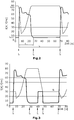
- Fig. 2 a cyclical course of a motor current and the speed of the vacuum pump according to the prior art and the Fig. 3 the corresponding graphs according to the invention.
- the curve of the motor current I represented by a thick line shows, in conventional applications, at a point in time t 1 at which the valve is opened, a sharp increase in current from I min to I max .
- the same increase in current occurs again after a cycle duration t z at a further point in time t 1 .
- the controller 30 can thus determine the cycle duration t z on the basis of the current increase occurring at cyclical intervals at the times t 1. This determination is independent of the knowledge when the valve 26 is actually opened. This is of interest insofar as no signal is often generated or output which informs the control that the valve is being opened or when it is being opened.
- the control according to the invention is self-learning in that it also can automatically determine the new cycle duration in the event of changing processes.
- the curve of the current curve represented by a thick line shows that after the current rise at time t 1, it first slowly and then falls again relatively quickly, so that at time t 2 the electric motor takes up the minimum current I min again.
- the period of time t 1 to t 2 is the load duration, ie that period of time in which the evacuation of the lock chamber 12 takes place.
- the course of the speed of the corresponding vacuum pump is shown as a thin line.
- time t 1 that is, when the valve 26 is opened, the pressure at the pump inlet increases suddenly, so that the speed of the pump falls.
- the pump speed then rises to a maximum value and then remains at this maximum speed until the next time the valve is opened at the further point in time t 1 .
- the engine speed is already reduced well before time t 1 , at which the valve 26 is opened.
- the engine speed is increased from its maximum speed at which it is during the evacuation of the lock chamber 12 a significantly lower speed.
- the time t 3 is later than a time t 2 , so that the evacuation of the lock chamber has already taken place at the time t 3 or the load duration t L has ended.
- Defined braking is again preferably carried out with the aid of the controller 30 up to a point in time t 4 .
- the current rises briefly and falls again to the minimum value at time t 4.
- the speed of the motor is therefore significantly lower than the maximum speed from time t 4.
- the motor does not have the maximum speed as in the prior art, but a significantly reduced speed.
- the kinetic energy released during braking between t 3 and t 4 can be fed back into the supply network via a feedback unit. This can increase the energy efficiency of a vacuum pump, which leads to cost savings for the operator.
- the Figure 4 shows schematically a vacuum pump 40, which is, for example, the vacuum pump 20 or 22 ( Figure 1 ) can act.
- the vacuum pump 40 has an electric motor 42 by which a pump rotor 44 is driven.
- the electric motor 42 is driven or controlled in the illustrated embodiment via a frequency converter 46.
- the frequency converter 46 is connected to the supply network 48.
- the electric motor 42 is used as a generator due to the considerable kinetic energy.
- the electrical energy produced in this way is fed via the frequency converter into an energy recovery unit 50 and can then be fed back to the supply network 48 via the lines shown.
- the connection of the frequency converter 46 to the supply network 48 via the energy recovery unit 50 is also provided.
- the energy recovery unit 50 thus simultaneously serves as a feed unit.
Landscapes
- Engineering & Computer Science (AREA)
- Mechanical Engineering (AREA)
- General Engineering & Computer Science (AREA)
- Computer Hardware Design (AREA)
- Physics & Mathematics (AREA)
- Fluid Mechanics (AREA)
- Control Of Positive-Displacement Pumps (AREA)
- Applications Or Details Of Rotary Compressors (AREA)
- Compressors, Vaccum Pumps And Other Relevant Systems (AREA)
- Control Of Fluid Pressure (AREA)
Claims (8)
- Procédé de fonctionnement d'un système de pompe à vide afin d'évacuer une chambre, en particulier une chambre de sas (12), en particulier reliée à une chambre de traitement (10),
dans lequel le système de pompe à vide comporte au moins un dispositif de pompe à vide (18) comprenant au moins une pompe à vide (20, 22), un dispositif de vanne (26) disposé entre le dispositif de pompe à vide (18) et la chambre (12) et un dispositif de commande (30),
dans lequel au moins un paramètre opérationnel cyclique du système de pompe à vide est déterminé au moyen du dispositif de commande (30) et
une vitesse de rotation d'au moins une des pompes à vide (20, 22) du dispositif de pompe à vide (18) est diminuée avant une ouverture du dispositif de vanne (26),
caractérisé en ce qu'une durée de cycle (tz) est déterminée comme période entre deux variations identiques d'un paramètre opérationnel, dans lequel la vitesse de rotation d'au moins une des pompes à vide (20, 22) du dispositif de pompe à vide (18) est diminuée au plus tard à la fin, de préférence avant la fin, d'une durée de cycle (tz) . - Procédé selon la revendication 1, dans lequel est sélectionné comme paramètre opérationnel un paramètre opérationnel variant de manière significative lors de l'ouverture du dispositif de vanne (26).
- Procédé selon la revendication 1 ou 2, dans lequel est déterminé comme paramètre opérationnel un courant moteur d'un moteur entraînant une pompe à vide (20, 22) du dispositif de pompe à vide (18), dans lequel une augmentation, en particulier significative, du courant moteur est associée à une ouverture du dispositif de vanne (26).
- Procédé selon l'une des revendications 1 à 3, dans lequel est déterminé comme paramètre opérationnel une pression d'entrée du dispositif de pompe à vide (18) et/ou une pression d'entrée d'au moins une des pompes à vide (20, 22) du dispositif de pompe à vide (18) et/ou une température d'au moins une des pompes à vide et/ou un déplacement d'une vanne de décompression entre l'entrée et la sortie d'au moins une des pompes à vide (20, 22) du dispositif de pompe à vide (18).
- Procédé selon l'une des revendications 1 à 4, dans lequel la vitesse de rotation de l'au moins une pompe à vide (20, 22) s'accroît après l'ouverture du dispositif de vanne (26).
- Procédé selon l'une des revendications 1 à 5, dans lequel est définie, à l'aide d'au moins un paramètre opérationnel, une durée de charge (tL) durant laquelle la chambre (12) est évacuée jusqu'à un vide prédéfini.
- Procédé selon la revendication 6, dans lequel à un instant (t3) après la durée de charge (tL) une réduction de la vitesse de rotation de la pompe s'effectue et la vitesse de rotation de la pompe reste réduite pour le reste de la durée de cycle.
- Procédé selon l'une des revendications 1 à 7, lors duquel l'énergie électrique de freinage obtenue lors de la diminution de la vitesse de rotation d'au moins une des pompes à vide (20, 22) du dispositif de pompe à vide (18) est stockée dans une unité accumulatrice d'énergie (50) ou est réinjectée dans le réseau d'alimentation au moins d'une unité de régénération d'énergie (50).
Applications Claiming Priority (2)
| Application Number | Priority Date | Filing Date | Title |
|---|---|---|---|
| DE102016223782.9A DE102016223782A1 (de) | 2016-11-30 | 2016-11-30 | Verfahren zum Betreiben eines Vakuumpumpensystems |
| PCT/EP2017/078852 WO2018099710A1 (fr) | 2016-11-30 | 2017-11-10 | Procédé permettant de faire fonctionner un système de pompage à vide |
Publications (2)
| Publication Number | Publication Date |
|---|---|
| EP3548745A1 EP3548745A1 (fr) | 2019-10-09 |
| EP3548745B1 true EP3548745B1 (fr) | 2021-03-17 |
Family
ID=60409284
Family Applications (1)
| Application Number | Title | Priority Date | Filing Date |
|---|---|---|---|
| EP17801030.2A Active EP3548745B1 (fr) | 2016-11-30 | 2017-11-10 | Procédé permettant de faire fonctionner un système de pompage à vide |
Country Status (8)
| Country | Link |
|---|---|
| US (1) | US11719231B2 (fr) |
| EP (1) | EP3548745B1 (fr) |
| JP (1) | JP7445427B2 (fr) |
| KR (1) | KR20190088482A (fr) |
| CN (1) | CN110036200A (fr) |
| DE (1) | DE102016223782A1 (fr) |
| MY (1) | MY196928A (fr) |
| WO (1) | WO2018099710A1 (fr) |
Families Citing this family (2)
| Publication number | Priority date | Publication date | Assignee | Title |
|---|---|---|---|---|
| BE1028135B1 (nl) * | 2020-03-10 | 2021-10-11 | Atlas Copco Airpower Nv | Werkwijze en inrichting voor het regelen van de pompsnelheid, computerprogramma en een door een computer leesbaar medium waarop het computerprogramma is opgeslagen daarbij toegepast en een pomp |
| EP4696893A1 (fr) * | 2025-12-11 | 2026-02-18 | Pfeiffer Vacuum Technology AG | Ensemble pompe |
Family Cites Families (18)
| Publication number | Priority date | Publication date | Assignee | Title |
|---|---|---|---|---|
| US6022195A (en) * | 1988-09-13 | 2000-02-08 | Helix Technology Corporation | Electronically controlled vacuum pump with control module |
| US5094885A (en) | 1990-10-12 | 1992-03-10 | Genus, Inc. | Differential pressure cvd chuck |
| IT1286223B1 (it) | 1996-09-18 | 1998-07-08 | Awax Progettazione | Apparato per il confezionamento di prodotti in atmosfera modificata e controllata, con film estensibile ed impermeabile al gas |
| JP2000110735A (ja) * | 1998-10-01 | 2000-04-18 | Internatl Business Mach Corp <Ibm> | ポンプ保護装置、ポンプ保護方法及びポンプ装置 |
| JP2002180990A (ja) * | 2000-12-11 | 2002-06-26 | Ebara Corp | 真空ポンプ制御装置 |
| JP2003155981A (ja) * | 2001-11-21 | 2003-05-30 | Toyota Industries Corp | 真空ポンプにおける運転制御方法及び運転制御装置 |
| DE10255792C5 (de) | 2002-11-28 | 2008-12-18 | Vacuubrand Gmbh + Co Kg | Verfahren zur Steuerung einer Vakuumpumpe sowie Vakuumpumpensystem |
| JP2004197644A (ja) * | 2002-12-18 | 2004-07-15 | Toyota Industries Corp | 真空ポンプの制御装置 |
| DE102007060174A1 (de) | 2007-12-13 | 2009-06-25 | Oerlikon Leybold Vacuum Gmbh | Vakuumpumpe sowie Verfahren zum Betreiben einer Vakuumpumpe |
| US8484961B2 (en) * | 2009-04-10 | 2013-07-16 | Ford Global Technologies, Llc | Vacuum accumulator system and method for regenerative braking system |
| KR100953626B1 (ko) * | 2009-06-18 | 2010-04-20 | 캄텍주식회사 | 차량용 진공펌프 |
| US9080576B2 (en) * | 2011-02-13 | 2015-07-14 | Applied Materials, Inc. | Method and apparatus for controlling a processing system |
| GB2492065A (en) | 2011-06-16 | 2012-12-26 | Edwards Ltd | Noise reduction of a vacuum pumping system |
| EP2644841A1 (fr) * | 2012-03-29 | 2013-10-02 | Alstom Technology Ltd | Procédé de fonctionnement d'un moteur à turbine après l'arrêt de flamme |
| JP5933837B2 (ja) | 2012-07-09 | 2016-06-15 | サン−ゴバン グラス フランスSaint−Gobain Glass France | 基板を処理するためのシステムと方法 |
| DE102013223556A1 (de) | 2013-11-19 | 2015-05-21 | Oerlikon Leybold Vacuum Gmbh | Vakuumpumpen-System sowie Verfahren zum Betreiben eines Vakuumpumpen-Systems |
| EP3015328B1 (fr) * | 2014-10-30 | 2017-09-20 | KNORR-BREMSE Systeme für Nutzfahrzeuge GmbH | Système à air comprimé pour véhicule automobile |
| CN104728219A (zh) * | 2015-03-17 | 2015-06-24 | 长安大学 | 一种具有能量回收功能的液压泵试验台系统及能量回收方法 |
-
2016
- 2016-11-30 DE DE102016223782.9A patent/DE102016223782A1/de not_active Withdrawn
-
2017
- 2017-11-10 WO PCT/EP2017/078852 patent/WO2018099710A1/fr not_active Ceased
- 2017-11-10 CN CN201780071741.0A patent/CN110036200A/zh active Pending
- 2017-11-10 EP EP17801030.2A patent/EP3548745B1/fr active Active
- 2017-11-10 MY MYPI2019003136A patent/MY196928A/en unknown
- 2017-11-10 KR KR1020197015636A patent/KR20190088482A/ko not_active Ceased
- 2017-11-10 JP JP2019528620A patent/JP7445427B2/ja active Active
- 2017-11-10 US US16/463,602 patent/US11719231B2/en active Active
Non-Patent Citations (1)
| Title |
|---|
| None * |
Also Published As
| Publication number | Publication date |
|---|---|
| DE102016223782A1 (de) | 2018-05-30 |
| EP3548745A1 (fr) | 2019-10-09 |
| CN110036200A (zh) | 2019-07-19 |
| JP7445427B2 (ja) | 2024-03-07 |
| WO2018099710A1 (fr) | 2018-06-07 |
| JP2020501068A (ja) | 2020-01-16 |
| MY196928A (en) | 2023-05-11 |
| KR20190088482A (ko) | 2019-07-26 |
| US20210381499A1 (en) | 2021-12-09 |
| US11719231B2 (en) | 2023-08-08 |
Similar Documents
| Publication | Publication Date | Title |
|---|---|---|
| DE2745291C2 (de) | Verfahren zum Zuführen von Werkstoffstreifen in eine Bearbeitungsmaschine und Einrichtung zur Durchführung des Verfahrens | |
| DE2428649C3 (de) | Vorrichtung zum Steuern eines Betätigungshebels einer Synchronisationseinrichtung eines Wechselgetriebes | |
| EP2420681B1 (fr) | Entraînement linéaire hydraulique | |
| DE10110398A1 (de) | Verfahren zur Regelung der Druckmittelzufuhr zu einem hydraulisch betätigten Aktor | |
| EP3548745B1 (fr) | Procédé permettant de faire fonctionner un système de pompage à vide | |
| DE102013216017A1 (de) | Softstart-Fensterheber | |
| DE102014226634B3 (de) | Verfahren zum Betreiben eines hydraulischen Antriebs, Recheneinheit, Computerprogramm und maschinenlesbares Speichermedium | |
| EP2192309A2 (fr) | Procédé et commutation de réglage destinés au réglage d'une arrivée de moyen de pression pour un actionneur hydraulique | |
| DE102009018071A1 (de) | Verfahren und Regelvorrichtung zur Regelung einer Druckmittelzufuhr für einen hydraulischen Aktor | |
| DE102014219536A1 (de) | Verfahren zur Ermittlung einer Betätigungskraft eines Stellaktuators | |
| EP0654608A1 (fr) | Procédé pour commander le mouvement d'un vérin à fluide et vérin à fluide | |
| EP1404986B1 (fr) | Procede de vidange acceleree d'un ralentisseur hydrodynamique et ralentisseur hydrodynamique | |
| EP3311028B1 (fr) | Procédé pour comprimer un gaz, unité de calcul et compresseur à piston polyétagé | |
| EP1423249A2 (fr) | Dispositif de serrage electromecanique | |
| EP3555475B1 (fr) | Système de pompe à vide et son procédé de fonctionnement | |
| DE1252303B (de) | Elektrischer Regler | |
| DE102019119392B4 (de) | Vorrichtung und Verfahren zur Steuerung oder Regelung einer Bewegung eines Ziehkissens einer Ziehkissenpresse und Ziehkissenpresse | |
| DE102016206709A1 (de) | Versorgungseinrichtung, Versorgungssystem und Verfahren zur individuellen Versorgung eines Druckluftverbrauchers | |
| EP2593679B1 (fr) | Groupe hydraulique | |
| DE102019004338A1 (de) | HYDRAULlSCHER ZYLlNDERANTRlEB UND HYDRAULlSCHER PRESSENANTRlEB SOWlE HYDRAULlSCHES ANTRlEBSVERFAHREN | |
| EP2053249A2 (fr) | Agencement doté d'une pompe à vide et procédé | |
| DE102005052716B4 (de) | Steuergerät und Steuerverfahren für ein Getriebe | |
| EP3157727A1 (fr) | Procédé pour faire fonctionner une machine de moulage par injection | |
| DE102014226617A1 (de) | Antriebsregelvorrichtung für einen elektro-hydraulischen Antrieb | |
| EP3380314B1 (fr) | Procédé de fonctionnement d'une presse, en particulier d'une presse d'estampage à vilebrequin |
Legal Events
| Date | Code | Title | Description |
|---|---|---|---|
| STAA | Information on the status of an ep patent application or granted ep patent |
Free format text: STATUS: UNKNOWN |
|
| STAA | Information on the status of an ep patent application or granted ep patent |
Free format text: STATUS: THE INTERNATIONAL PUBLICATION HAS BEEN MADE |
|
| PUAI | Public reference made under article 153(3) epc to a published international application that has entered the european phase |
Free format text: ORIGINAL CODE: 0009012 |
|
| STAA | Information on the status of an ep patent application or granted ep patent |
Free format text: STATUS: REQUEST FOR EXAMINATION WAS MADE |
|
| 17P | Request for examination filed |
Effective date: 20190531 |
|
| AK | Designated contracting states |
Kind code of ref document: A1 Designated state(s): AL AT BE BG CH CY CZ DE DK EE ES FI FR GB GR HR HU IE IS IT LI LT LU LV MC MK MT NL NO PL PT RO RS SE SI SK SM TR |
|
| AX | Request for extension of the european patent |
Extension state: BA ME |
|
| DAV | Request for validation of the european patent (deleted) | ||
| DAX | Request for extension of the european patent (deleted) | ||
| GRAP | Despatch of communication of intention to grant a patent |
Free format text: ORIGINAL CODE: EPIDOSNIGR1 |
|
| STAA | Information on the status of an ep patent application or granted ep patent |
Free format text: STATUS: GRANT OF PATENT IS INTENDED |
|
| INTG | Intention to grant announced |
Effective date: 20201116 |
|
| GRAS | Grant fee paid |
Free format text: ORIGINAL CODE: EPIDOSNIGR3 |
|
| GRAA | (expected) grant |
Free format text: ORIGINAL CODE: 0009210 |
|
| STAA | Information on the status of an ep patent application or granted ep patent |
Free format text: STATUS: THE PATENT HAS BEEN GRANTED |
|
| AK | Designated contracting states |
Kind code of ref document: B1 Designated state(s): AL AT BE BG CH CY CZ DE DK EE ES FI FR GB GR HR HU IE IS IT LI LT LU LV MC MK MT NL NO PL PT RO RS SE SI SK SM TR |
|
| REG | Reference to a national code |
Ref country code: GB Ref legal event code: FG4D Free format text: NOT ENGLISH |
|
| REG | Reference to a national code |
Ref country code: CH Ref legal event code: EP |
|
| REG | Reference to a national code |
Ref country code: DE Ref legal event code: R096 Ref document number: 502017009758 Country of ref document: DE |
|
| REG | Reference to a national code |
Ref country code: IE Ref legal event code: FG4D Free format text: LANGUAGE OF EP DOCUMENT: GERMAN |
|
| REG | Reference to a national code |
Ref country code: AT Ref legal event code: REF Ref document number: 1372481 Country of ref document: AT Kind code of ref document: T Effective date: 20210415 |
|
| REG | Reference to a national code |
Ref country code: LT Ref legal event code: MG9D |
|
| PG25 | Lapsed in a contracting state [announced via postgrant information from national office to epo] |
Ref country code: NO Free format text: LAPSE BECAUSE OF FAILURE TO SUBMIT A TRANSLATION OF THE DESCRIPTION OR TO PAY THE FEE WITHIN THE PRESCRIBED TIME-LIMIT Effective date: 20210617 Ref country code: FI Free format text: LAPSE BECAUSE OF FAILURE TO SUBMIT A TRANSLATION OF THE DESCRIPTION OR TO PAY THE FEE WITHIN THE PRESCRIBED TIME-LIMIT Effective date: 20210317 Ref country code: HR Free format text: LAPSE BECAUSE OF FAILURE TO SUBMIT A TRANSLATION OF THE DESCRIPTION OR TO PAY THE FEE WITHIN THE PRESCRIBED TIME-LIMIT Effective date: 20210317 Ref country code: GR Free format text: LAPSE BECAUSE OF FAILURE TO SUBMIT A TRANSLATION OF THE DESCRIPTION OR TO PAY THE FEE WITHIN THE PRESCRIBED TIME-LIMIT Effective date: 20210618 Ref country code: BG Free format text: LAPSE BECAUSE OF FAILURE TO SUBMIT A TRANSLATION OF THE DESCRIPTION OR TO PAY THE FEE WITHIN THE PRESCRIBED TIME-LIMIT Effective date: 20210617 |
|
| REG | Reference to a national code |
Ref country code: NL Ref legal event code: MP Effective date: 20210317 |
|
| PG25 | Lapsed in a contracting state [announced via postgrant information from national office to epo] |
Ref country code: SE Free format text: LAPSE BECAUSE OF FAILURE TO SUBMIT A TRANSLATION OF THE DESCRIPTION OR TO PAY THE FEE WITHIN THE PRESCRIBED TIME-LIMIT Effective date: 20210317 Ref country code: RS Free format text: LAPSE BECAUSE OF FAILURE TO SUBMIT A TRANSLATION OF THE DESCRIPTION OR TO PAY THE FEE WITHIN THE PRESCRIBED TIME-LIMIT Effective date: 20210317 Ref country code: LV Free format text: LAPSE BECAUSE OF FAILURE TO SUBMIT A TRANSLATION OF THE DESCRIPTION OR TO PAY THE FEE WITHIN THE PRESCRIBED TIME-LIMIT Effective date: 20210317 |
|
| PG25 | Lapsed in a contracting state [announced via postgrant information from national office to epo] |
Ref country code: NL Free format text: LAPSE BECAUSE OF FAILURE TO SUBMIT A TRANSLATION OF THE DESCRIPTION OR TO PAY THE FEE WITHIN THE PRESCRIBED TIME-LIMIT Effective date: 20210317 |
|
| PG25 | Lapsed in a contracting state [announced via postgrant information from national office to epo] |
Ref country code: LT Free format text: LAPSE BECAUSE OF FAILURE TO SUBMIT A TRANSLATION OF THE DESCRIPTION OR TO PAY THE FEE WITHIN THE PRESCRIBED TIME-LIMIT Effective date: 20210317 Ref country code: EE Free format text: LAPSE BECAUSE OF FAILURE TO SUBMIT A TRANSLATION OF THE DESCRIPTION OR TO PAY THE FEE WITHIN THE PRESCRIBED TIME-LIMIT Effective date: 20210317 Ref country code: CZ Free format text: LAPSE BECAUSE OF FAILURE TO SUBMIT A TRANSLATION OF THE DESCRIPTION OR TO PAY THE FEE WITHIN THE PRESCRIBED TIME-LIMIT Effective date: 20210317 Ref country code: SM Free format text: LAPSE BECAUSE OF FAILURE TO SUBMIT A TRANSLATION OF THE DESCRIPTION OR TO PAY THE FEE WITHIN THE PRESCRIBED TIME-LIMIT Effective date: 20210317 |
|
| PG25 | Lapsed in a contracting state [announced via postgrant information from national office to epo] |
Ref country code: IS Free format text: LAPSE BECAUSE OF FAILURE TO SUBMIT A TRANSLATION OF THE DESCRIPTION OR TO PAY THE FEE WITHIN THE PRESCRIBED TIME-LIMIT Effective date: 20210717 Ref country code: PL Free format text: LAPSE BECAUSE OF FAILURE TO SUBMIT A TRANSLATION OF THE DESCRIPTION OR TO PAY THE FEE WITHIN THE PRESCRIBED TIME-LIMIT Effective date: 20210317 Ref country code: PT Free format text: LAPSE BECAUSE OF FAILURE TO SUBMIT A TRANSLATION OF THE DESCRIPTION OR TO PAY THE FEE WITHIN THE PRESCRIBED TIME-LIMIT Effective date: 20210719 Ref country code: SK Free format text: LAPSE BECAUSE OF FAILURE TO SUBMIT A TRANSLATION OF THE DESCRIPTION OR TO PAY THE FEE WITHIN THE PRESCRIBED TIME-LIMIT Effective date: 20210317 Ref country code: RO Free format text: LAPSE BECAUSE OF FAILURE TO SUBMIT A TRANSLATION OF THE DESCRIPTION OR TO PAY THE FEE WITHIN THE PRESCRIBED TIME-LIMIT Effective date: 20210317 |
|
| REG | Reference to a national code |
Ref country code: DE Ref legal event code: R097 Ref document number: 502017009758 Country of ref document: DE |
|
| PLBE | No opposition filed within time limit |
Free format text: ORIGINAL CODE: 0009261 |
|
| STAA | Information on the status of an ep patent application or granted ep patent |
Free format text: STATUS: NO OPPOSITION FILED WITHIN TIME LIMIT |
|
| PG25 | Lapsed in a contracting state [announced via postgrant information from national office to epo] |
Ref country code: ES Free format text: LAPSE BECAUSE OF FAILURE TO SUBMIT A TRANSLATION OF THE DESCRIPTION OR TO PAY THE FEE WITHIN THE PRESCRIBED TIME-LIMIT Effective date: 20210317 Ref country code: DK Free format text: LAPSE BECAUSE OF FAILURE TO SUBMIT A TRANSLATION OF THE DESCRIPTION OR TO PAY THE FEE WITHIN THE PRESCRIBED TIME-LIMIT Effective date: 20210317 Ref country code: AL Free format text: LAPSE BECAUSE OF FAILURE TO SUBMIT A TRANSLATION OF THE DESCRIPTION OR TO PAY THE FEE WITHIN THE PRESCRIBED TIME-LIMIT Effective date: 20210317 |
|
| 26N | No opposition filed |
Effective date: 20211220 |
|
| PG25 | Lapsed in a contracting state [announced via postgrant information from national office to epo] |
Ref country code: SI Free format text: LAPSE BECAUSE OF FAILURE TO SUBMIT A TRANSLATION OF THE DESCRIPTION OR TO PAY THE FEE WITHIN THE PRESCRIBED TIME-LIMIT Effective date: 20210317 |
|
| PG25 | Lapsed in a contracting state [announced via postgrant information from national office to epo] |
Ref country code: IT Free format text: LAPSE BECAUSE OF FAILURE TO SUBMIT A TRANSLATION OF THE DESCRIPTION OR TO PAY THE FEE WITHIN THE PRESCRIBED TIME-LIMIT Effective date: 20210317 |
|
| PG25 | Lapsed in a contracting state [announced via postgrant information from national office to epo] |
Ref country code: IS Free format text: LAPSE BECAUSE OF FAILURE TO SUBMIT A TRANSLATION OF THE DESCRIPTION OR TO PAY THE FEE WITHIN THE PRESCRIBED TIME-LIMIT Effective date: 20210717 |
|
| PG25 | Lapsed in a contracting state [announced via postgrant information from national office to epo] |
Ref country code: MC Free format text: LAPSE BECAUSE OF FAILURE TO SUBMIT A TRANSLATION OF THE DESCRIPTION OR TO PAY THE FEE WITHIN THE PRESCRIBED TIME-LIMIT Effective date: 20210317 |
|
| PG25 | Lapsed in a contracting state [announced via postgrant information from national office to epo] |
Ref country code: LU Free format text: LAPSE BECAUSE OF NON-PAYMENT OF DUE FEES Effective date: 20211110 Ref country code: BE Free format text: LAPSE BECAUSE OF NON-PAYMENT OF DUE FEES Effective date: 20211130 |
|
| REG | Reference to a national code |
Ref country code: BE Ref legal event code: MM Effective date: 20211130 |
|
| PG25 | Lapsed in a contracting state [announced via postgrant information from national office to epo] |
Ref country code: IE Free format text: LAPSE BECAUSE OF NON-PAYMENT OF DUE FEES Effective date: 20211110 |
|
| P01 | Opt-out of the competence of the unified patent court (upc) registered |
Effective date: 20230424 |
|
| PG25 | Lapsed in a contracting state [announced via postgrant information from national office to epo] |
Ref country code: CY Free format text: LAPSE BECAUSE OF FAILURE TO SUBMIT A TRANSLATION OF THE DESCRIPTION OR TO PAY THE FEE WITHIN THE PRESCRIBED TIME-LIMIT Effective date: 20210317 |
|
| PG25 | Lapsed in a contracting state [announced via postgrant information from national office to epo] |
Ref country code: HU Free format text: LAPSE BECAUSE OF FAILURE TO SUBMIT A TRANSLATION OF THE DESCRIPTION OR TO PAY THE FEE WITHIN THE PRESCRIBED TIME-LIMIT; INVALID AB INITIO Effective date: 20171110 |
|
| REG | Reference to a national code |
Ref country code: AT Ref legal event code: MM01 Ref document number: 1372481 Country of ref document: AT Kind code of ref document: T Effective date: 20221110 |
|
| PG25 | Lapsed in a contracting state [announced via postgrant information from national office to epo] |
Ref country code: AT Free format text: LAPSE BECAUSE OF NON-PAYMENT OF DUE FEES Effective date: 20221110 |
|
| PG25 | Lapsed in a contracting state [announced via postgrant information from national office to epo] |
Ref country code: MK Free format text: LAPSE BECAUSE OF FAILURE TO SUBMIT A TRANSLATION OF THE DESCRIPTION OR TO PAY THE FEE WITHIN THE PRESCRIBED TIME-LIMIT Effective date: 20210317 |
|
| PG25 | Lapsed in a contracting state [announced via postgrant information from national office to epo] |
Ref country code: TR Free format text: LAPSE BECAUSE OF FAILURE TO SUBMIT A TRANSLATION OF THE DESCRIPTION OR TO PAY THE FEE WITHIN THE PRESCRIBED TIME-LIMIT Effective date: 20210317 |
|
| PG25 | Lapsed in a contracting state [announced via postgrant information from national office to epo] |
Ref country code: MT Free format text: LAPSE BECAUSE OF FAILURE TO SUBMIT A TRANSLATION OF THE DESCRIPTION OR TO PAY THE FEE WITHIN THE PRESCRIBED TIME-LIMIT Effective date: 20210317 |
|
| REG | Reference to a national code |
Ref country code: CH Ref legal event code: U11 Free format text: ST27 STATUS EVENT CODE: U-0-0-U10-U11 (AS PROVIDED BY THE NATIONAL OFFICE) Effective date: 20251201 |
|
| PGFP | Annual fee paid to national office [announced via postgrant information from national office to epo] |
Ref country code: DE Payment date: 20251128 Year of fee payment: 9 |
|
| PGFP | Annual fee paid to national office [announced via postgrant information from national office to epo] |
Ref country code: GB Payment date: 20251127 Year of fee payment: 9 |
|
| PGFP | Annual fee paid to national office [announced via postgrant information from national office to epo] |
Ref country code: FR Payment date: 20251125 Year of fee payment: 9 |
|
| PGFP | Annual fee paid to national office [announced via postgrant information from national office to epo] |
Ref country code: CH Payment date: 20251201 Year of fee payment: 9 |