EP3551354B1 - Commande de largeur et de vitesse pour décalamineuse de tôle métallique et procédés faisant appel à celle-ci - Google Patents
Commande de largeur et de vitesse pour décalamineuse de tôle métallique et procédés faisant appel à celle-ci Download PDFInfo
- Publication number
- EP3551354B1 EP3551354B1 EP18842696.9A EP18842696A EP3551354B1 EP 3551354 B1 EP3551354 B1 EP 3551354B1 EP 18842696 A EP18842696 A EP 18842696A EP 3551354 B1 EP3551354 B1 EP 3551354B1
- Authority
- EP
- European Patent Office
- Prior art keywords
- sheet metal
- wheel
- center
- sheet
- nozzle
- Prior art date
- Legal status (The legal status is an assumption and is not a legal conclusion. Google has not performed a legal analysis and makes no representation as to the accuracy of the status listed.)
- Not-in-force
Links
Images



Classifications
-
- B—PERFORMING OPERATIONS; TRANSPORTING
- B21—MECHANICAL METAL-WORKING WITHOUT ESSENTIALLY REMOVING MATERIAL; PUNCHING METAL
- B21B—ROLLING OF METAL
- B21B45/00—Devices for surface or other treatment of work, specially combined with or arranged in, or specially adapted for use in connection with, metal-rolling mills
- B21B45/04—Devices for surface or other treatment of work, specially combined with or arranged in, or specially adapted for use in connection with, metal-rolling mills for de-scaling, e.g. by brushing
- B21B45/06—Devices for surface or other treatment of work, specially combined with or arranged in, or specially adapted for use in connection with, metal-rolling mills for de-scaling, e.g. by brushing of strip material
-
- B—PERFORMING OPERATIONS; TRANSPORTING
- B24—GRINDING; POLISHING
- B24C—ABRASIVE OR RELATED BLASTING WITH PARTICULATE MATERIAL
- B24C1/00—Methods for use of abrasive blasting for producing particular effects; Use of auxiliary equipment in connection with such methods
- B24C1/08—Methods for use of abrasive blasting for producing particular effects; Use of auxiliary equipment in connection with such methods for polishing surfaces, e.g. smoothing a surface by making use of liquid-borne abrasives
- B24C1/086—Descaling; Removing coating films
-
- B—PERFORMING OPERATIONS; TRANSPORTING
- B24—GRINDING; POLISHING
- B24C—ABRASIVE OR RELATED BLASTING WITH PARTICULATE MATERIAL
- B24C3/00—Abrasive blasting machines or devices; Plants
- B24C3/02—Abrasive blasting machines or devices; Plants characterised by the arrangement of the component assemblies with respect to each other
- B24C3/06—Abrasive blasting machines or devices; Plants characterised by the arrangement of the component assemblies with respect to each other movable; portable
-
- B—PERFORMING OPERATIONS; TRANSPORTING
- B24—GRINDING; POLISHING
- B24C—ABRASIVE OR RELATED BLASTING WITH PARTICULATE MATERIAL
- B24C3/00—Abrasive blasting machines or devices; Plants
- B24C3/08—Abrasive blasting machines or devices; Plants essentially adapted for abrasive blasting of travelling stock or travelling workpieces
- B24C3/10—Abrasive blasting machines or devices; Plants essentially adapted for abrasive blasting of travelling stock or travelling workpieces for treating external surfaces
- B24C3/14—Apparatus using impellers
-
- B—PERFORMING OPERATIONS; TRANSPORTING
- B24—GRINDING; POLISHING
- B24C—ABRASIVE OR RELATED BLASTING WITH PARTICULATE MATERIAL
- B24C5/00—Devices or accessories for generating abrasive blasts
- B24C5/06—Impeller wheels; Rotor blades therefor
Definitions
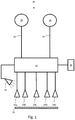
- FIG. 1 shows a schematic drawing of a control 20.
- the control 20 includes a processor 22 that receive input from sensors 24a-24e that sense the surface condition of sheet metal 26 as it is processed in a descaler.
- the sensors may be cameras, profilometers, and/or other measuring devices configured to sense the surface condition of sheet metal as it is being processed in the descaler.
- the sensors are first and second edge sensors and a center sensor 24c, and may be intermediate sensors 24b,24d.
- the first and second edge sensors 22a,22e are configured to sense the condition of the surface of the sheet metal 26 at lateral opposite side edges of the sheet metal.
- the center sensor 24c is configured to sense the condition of the surface of the sheet metal at a center of the sheet metal.
- Intermediate sensors 24b,24d may be also provided to sense the condition of the surface of the sheet metal 26 at positions intermediate of the center and the lateral opposite side edges of the sheet metal.
- the intermediate sensors may be used as edge sensors and the edge sensors 24a,24e may be disabled from providing input to the control.
- Each of the sensors may provide input signals to the controller indicative of the condition of the surface of the sheet.
- a light 28 may also be provided to illuminate the surfaces of the sheet metal to allow the sensors to sense the surface condition of the sheet metal.
- the signals generated by the sensors are indicative of surface finish and/or general surface condition.
- the signals may be indicative of brightness, hue, and saturation associated with an image of the surface of the sheet metal.
- control 20 may comprise a system provided by Keyence Corp. of Itasca, IL, and in one embodiment, the processor 22 may include a model CV-X172 image sensor and a model CA-DC21 E light controller. To provide additional input from other cameras to the image sensor, the image sensor portion of the processor 22 may be provided with a model CV-E 500 camera extension unit.
- the processor may have one or more user interfaces 30 to allow programming of the processor, operation of the control 20, and remote monitoring of the signals obtained by the sensors 24a-24e. For instance, the processor may be programmed to allow remote viewing of the images obtained by the sensors via the user interfaces.
- the processor 22 may be configured to provide output signals 32,34 to programmable logic controls 36,38 associated with descaler or the processing line in which the descaler is employed.
- the output signals 32,34 may be provided via an ethernet connection or via an RS-232 type connection.
- the control 20 and processor 22 may be interfaced with the programmable logic control 38 associated with the recoiler and its tensioner to control the rate of advancement of the sheet through the descaling cell.
- the control 20 and processor 22 may also be interfaced with an actuator 36 associated with a nozzle 40 that directs the scale removing media to each impeller wheel 42 that propels scale removing media against the sheet 26.
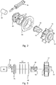
- Figures 2 and 3 provide additional detail of the nozzle actuator 36, nozzle 40, and impeller wheel 42.
- a supply of scale removing media is directed from a supply 44 to each wheel 42 through the nozzle 40 generally to the center of each impeller wheel.
- the nozzle 40 is rotatably mounted within hub plates 46, 48 and operatively connected to the nozzle actuator 36 such that operation of the actuator causes rotation of the nozzle 40 within the hub plates.
- the actuator 36 may be a linear actuator that is operatively pivotally connected to an outer flange of the nozzle 40. Thus, linear motion of the linear actuator may produce rotational motion of the nozzle within the hub plates 46,48.
- the impeller wheel may be mounted on a shaft 50 driven by an electric motor (not shown).
- the impeller wheel 42 may have a hollow center that communicates radially with the veins of the impeller wheel.
- An opening 52 to the hollow center may be provided on the impeller wheel 42 axially opposite the shaft connection 50 to the impeller.
- the nozzle 40 may extend through the opening 52 and be disposed within the hollow center of the impeller wheel 42 with the hub plates 46,48 and associated disk seals 54 enclosing the opening.
- the nozzle 40 may have a tapered distal end 56. Actuation of the nozzle actuator 36 may in turn cause rotation of the nozzle 40 within the hub plates 46,48 and orient the tapered end 56 of the nozzle within the hollow center of the impeller wheel 42. Orienting the tapered end 56 of the nozzle at selected positions within the hollow center of the impeller wheel 42 enables changing of the location of the intensity of the spray within the blast pattern area, as will be explained below.
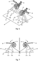
- Figures 4-11 show schematic views of the impeller wheels 42 associated with the sheet metal descaler and their positioning to achieve blast pattern areas 60,62 with different locations of spray intensity 64,66 relative to the advancing sheet 26 passing through the descaler. While the drawings show the top of the sheet and impellers propelling scale removing medium against the top of the sheet metal, in addition to or in the alternative, an identical arrangement may also be provided for the bottom of the sheet.
- the impeller wheels 42 are arranged on laterally opposite sides (e.g. opposite width edges) of the sheet 26 in a direction transverse to the direction of advancement of the sheet.
- the first impeller wheel propels scale removing media across the width of the sheet and produces the first blast pattern area 60.
- the second impeller wheel is positioned offset from the first wheel in the direction of advancement of the sheet so that the scale removing media propelled by the second wheel does not interfere with the scale removing media propelled by the first wheel.
- the second wheel also propels a scale removing media across the width of the sheet and produces the second blast pattern area 62.
- the first and second wheels are rotated in opposite directions so that each wheel propels the scale removing media from the lateral edge of the sheet toward the center of the sheet.
- the blast pattern areaS 60,62 overlap in the centerline of the sheet.
- the impeller wheels may rotate such that the scale removing media is propelled against the lateral side edges of sheet and towards the center of the sheet.
- the first wheel rotates in a clockwise direction so as to propel the scale removing media against an outer width edge of the sheet and then toward the center of the sheet.
- the second wheel rotates in the counterclockwise direction so as to propel the scale removing media toward the opposite, outer width edge of the sheet and then toward the center of the sheet.
- Figure 5 shows a front elevation view of the impellers and the actuator for the nozzle. The same general arrangement is shown in Figure 6-11 .
- the edge sensors 24a,24e and the center sensor 24c are provided to detect a surface condition of the sheet 26 after the scale removing medium has been propelled against the surface of the sheet by the first and second wheels 42.
- the center sensor 24c is configured to detect the surface condition of the surface of the sheet in a center of the width of the sheet.
- the edge sensor 24a is configured to detect the surface condition of the sheet metal adjacent to one side edge.
- the other edge sensor 24e is configured to detect the surface condition of the sheet adjacent to the opposite side edge.
- Intermediate sensors may be disposed between the center and edge sensor to provide further input to the control 20 and processor 22.
- the control is configured to: (a) receive signals indicative of a surface condition of the sheet as detected by the respective sensors, (b) compare the signals received from the center sensor with each of the signals received from the first and second edge sensors, and (c) transmit positional control signals to each of the nozzle actuators to rotate the respective nozzle relative to the wheel based upon the comparison of the signal of center signal with the signal of at least one of the first and second edge sensors.
- the intermediate sensors 24b,24d may provide signals to the control for further comparison to ensure the surface condition is uniform across the width of the sheet, or the intermediate sensors 24b,24d may be disabled from providing input to the control.
- the intermediate sensors 24b,24d may be used as edge sensors.
- the intermediate sensors 24b,24d may be located to coincide with the lateral width edges of narrow width sheets, for instance, as shown in Figures 8-11 .
- the edge sensors 24a,24e may be disabled from providing input to the control.
- the sensors may be used to provide input to the control for changing the location of the intensity of the spray 64,66 within the blast pattern areas 60,62 and/or changing the rate of advancement of the sheet through the descaler.
- Figure 12 shows one embodiment of a process flow for the controller.
- the sensors may provide input to the control to allow a determination that the surface condition of the processed sheet is consistent across a length. A length standard and length variation threshold may be established.
- control may be configured to send signals to the processing line controls (e.g., the PLC associated with the recoiler, or the PLC associated with tensioning rollers in the line) to take no action and maintain the rate of advancement of the sheet.
- the processing line controls e.g., the PLC associated with the recoiler, or the PLC associated with tensioning rollers in the line
- the control may be configured to send signals to the processing line controls to increase the rate of advancement of the sheet until condition L is met. If the comparison of the signal of the center sensor with the length standard indicates that the surface condition of the sheet is less favorable than the length standard (e.g., indicating that the surface condition of the center of the sheet is less than the specified limits), the control may be configured to send signals to the processing line controls to decrease the rate of advancement of the sheet until condition L is met. While the foregoing description uses the signal of the center sensor as a reference, the signals from other sensors may be used, and may be averaged, combined, or otherwise processed in the control to control the rate of advancement of the sheet.
- the sensors may provide input to the control to allow a determination that the surface condition of the processed sheet is consistent across the width.
- a width variation threshold may be established. If the comparison of the signals of the edge sensors with the signal of the center sensor is within the width variation threshold (e.g., indicating that the surface condition of the edges of the sheet is substantially the same as the surface condition of the center of the sheet, or within the allowable width variation threshold), the control may be configured to send signals to the nozzle actuator to take no action and maintain the current position of the nozzle relative to its respective wheels, thereby maintaining the location of the intensity of the spray in the blast pattern area.
- the control If the comparison of the edge sensor signals with the center sensor signals shows that the condition of the sheet in the center is more favorable than the condition of the sheet on a lateral side outside of the allowable width variation threshold, the control generates a signal to the nozzle actuator to reposition the nozzle within the impeller to shift the location of the intensity of the spray of the blast pattern area laterally outward relative to the sheet, for instance, away from the centerline of the sheet.
- the control If the comparison of the edge sensor signals with the center sensor signals shows that the condition of the sheet in the center is less favorable than the condition of the sheet on a lateral side outside of the allowable width variation threshold, the control generates a signal to the nozzle actuator to reposition the nozzle within the impeller to shift the location of the intensity of the spray of the blast pattern area laterally inward relative to the sheet, for instance, toward the centerline of the sheet.
- the control may be configured to send signals to control to each nozzle actuator and position each nozzle actuator independently of the other nozzle depending upon the signal generated by the respective sensor.
- the control may send signals to the respective nozzle actuator to reposition the nozzle for the impeller wheel for the effected side of the sheet, as needed.
- the intermediate sensors may be disable or provide signals that may be averaged, combined, or otherwise processed in the control to control the position of the nozzle actuator and the corresponding location of the intensity of the spray within the blast pattern area.
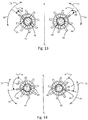
- the control may be configured to send signals to the nozzle actuator 36 to initially adjust the nozzle relative to the impeller wheel 42 to provide a set blast pattern area 60,62 across the width of the sheet based upon the size of the material being processed. For instance, as shown in Figure 13 , if the width of the material is 72 inches, the nozzle position relative to the impeller 42 will may be set at an angle 68 of about five degrees relative to a reference home position H. Once descaling operations begin, the control 20 may begin processing to determine whether the processed sheet has a surface condition consistent along its length and consistent along its width.
- the control 20 may send signals to the nozzle actuator 36 to rotate the nozzle 40 relative to the impeller wheel in direction 70 laterally inward toward the centerline of the sheet from the 5 degree off home position H, if the comparison of the signals from the edge sensor and the center sensor indicates that the surface condition on the lateral edges of the sheet is more favorable than the surface condition of the center of the sheet.
- the control 20 may send signals to the nozzle actuator 36 to rotate the nozzle 40 relative to the impeller wheel 42 in direction 72 laterally outward away from the centerline of the sheet from the 5 degree off home position H, if the comparison of the signals from the edge sensor and the center sensor indicates that the surface condition on the lateral edges of the sheet is less favorable than the surface condition of the center of the sheet.
- the control 20 may send signals to the nozzle actuator 36 to set the initial nozzle position 40 relative to the impeller at an angle 38 of about 15 degrees relative to a reference home position H.
- the control 20 may begin processing to determine whether the processed sheet has a surface condition consistent along its length and consistent along its width.
- the control 20 may send signals to the nozzle actuator 36 to rotate the nozzle 40 relative to the impeller wheel 42 in direction 70 laterally inward toward the centerline of the sheet from the 15 degree off home position H, if the comparison of the signals from the edge sensor and the center sensor indicates that the surface condition on the lateral edges of the sheet is more favorable than the surface condition of the center of the sheet.
- control 20 may send signals to the nozzle actuator 36 to rotate the nozzle relative to the impeller wheel in direction 72 laterally outward away from the centerline of the sheet from the 15 degree off home position H if the comparison of the signals from the edge sensor and the center sensor indicates that the surface condition on the lateral edges of the sheet is less favorable than the surface condition of the center of the sheet.
Landscapes
- Engineering & Computer Science (AREA)
- Mechanical Engineering (AREA)
- Cleaning In General (AREA)
- Nozzles (AREA)
- Spray Control Apparatus (AREA)
Claims (10)
- Appareil qui élimine la calamine de la tôle métallique, l'appareil comprenant :une décalamineuse qui reçoit des longueurs de tôle métallique (26) et enlève la calamine d'au moins une surface de la longueur de tôle métallique au fur et à mesure que la longueur de tôle métallique (26) est déplacée suivant un premier sens à travers la décalamineuse ;une alimentation (44) d'un produit d'élimination de calamine en communication avec la décalamineuse et fournissant le produit d'élimination de calamine à la décalamineuse via des première et deuxième buses (40), les première et deuxième buses possédant chacune un actionneur (36) configuré pour faire tourner la buse respective ;des première et deuxième roues (42) sur la décalamineuse positionnées de manière adjacente à l'au moins une surface de la longueur de tôle métallique (26) passée par la décalamineuse, chacune des première et deuxième roues (42) étant configurée pour recevoir le produit d'élimination de calamine à partir de l'alimentation (44) de produit d'élimination de calamine via les buses rotatives, la première roue ayant un axe de rotation qui est différent de la deuxième roue (42), la rotation de la première roue obligeant le produit d'élimination de calamine reçu par la première roue via la première buse à être projeté à partir de la première roue contre l'au moins une surface en travers de substantiellement toute une largeur de la tôle métallique et la rotation de la deuxième roue obligeant le produit d'élimination de calamine reçu par la deuxième roue via la deuxième buse à être projeté à partir de la deuxième roue contre l'au moins une surface en travers de substantiellement toute une largeur de la tôle métallique, la deuxième roue étant espacée de la première roue le long du premier sens sur une distance suffisante de telle sorte que le produit d'élimination de calamine projeté à partir de la deuxième roue n'interfère pas substantiellement avec le produit d'élimination de calamine projeté à partir de la première roue, la première roue et la deuxième roue étant positionnées de manière adjacente à des bords latéraux opposés définissant la largeur de la tôle métallique alors que la tôle métallique est centrée entre la première roue et la deuxième roue ; etun système de commande (20) en communication avec les actionneurs (36) des première et deuxième buses, la commande étant configurée pour : (a) recevoir des signaux indicatifs d'un état de surface de l'au moins une surface de la tôle métallique tel qu'il a été détecté par le capteur respectif,caractérisé en ce que le système de commande (20) est en communication avec au moins trois capteurs (24a, 24b, 24c, 24d, 24e) configurés pour détecter un état de surface de l'au moins une surface de la tôle métallique (26) une fois que le produit d'élimination de calamine a été projeté contre l'au moins une surface de la tôle métallique par les première et deuxième roues, un desdits au moins trois capteurs comprenant un capteur central (24c) configuré pour détecter l'état de surface de l'au moins une surface de la tôle métallique dans un centre de la largeur de la tôle, deux desdits au moins trois capteurs comprenant des capteurs de bord (24a, 24e), l'un des capteurs de bord étant configuré pour détecter l'état de surface de l'au moins une surface de la tôle métallique adjacente à un bord latéral définissant la largeur de la tôle métallique, l'autre des capteurs de bord étant configuré pour détecter l'état de surface de l'au moins une surface de la tôle métallique adjacente au côté latéral opposé définissant la largeur de la tôle métallique, la commande étant configurée en outre pour : (b) comparer les signaux reçus à partir du capteur central avec chacun des signaux reçus à partir des capteurs de bord, et (c) transmettre des signaux de commande de position à chacun des actionneurs de buse afin de faire tourner la buse respective relativement à la roue sur la base de la comparaison du signal de capteur central avec le signal d'au moins un des capteurs de bord, en ce quelorsque la comparaison du signal de capteur de bord au signal de capteur central est indicative du fait qu'un état de surface du bord respectif de l'au moins une surface de la tôle métallique est plus favorable qu'un état de surface du centre de l'au moins une surface de la tôle métallique, la commande est configurée pour transmettre le signal de commande de position à l'actionneur de buse afin de faire tourner la buse relativement à la roue respective d'une manière telle qu'une concentration du produit d'élimination de calamine projetée par la roue respective contre l'au moins une surface en travers de substantiellement toute une largeur de la tôle métallique se déplace vers le centre de la tôle métallique ; et en ce quelorsque la comparaison du signal de capteur de bord au signal de capteur central est indicative du fait qu'un état de surface du centre de l'au moins une surface de la tôle métallique est plus favorable qu'un état de surface du bord respectif de l'au moins une surface de la tôle métallique, la commande est configurée pour transmettre le signal de commande de position à l'actionneur de buse afin de faire tourner la buse relativement à la roue respective d'une manière telle qu'une concentration du produit d'élimination de calamine projetée par la roue respective contre l'au moins une surface en travers de substantiellement toute une largeur de la tôle métallique se déplace en éloignement par rapport au centre de la tôle métallique.
- Appareil de la revendication 1, dans lequel la commande (20) est configurée pour transmettre le signal de commande de position à un actionneur de buse (36) indépendamment de l'autre buse.
- Appareil de la revendication 1, dans lequel le produit d'élimination de calamine comprend une boue avec des grains abrasifs.
- Appareil de la revendication 1, dans lequel le capteur comprend une caméra.
- Appareil de la revendication 4, dans lequel les signaux indicatifs de l'état de surface de l'au moins une surface de la tôle métallique (26) comprennent des signaux indicatifs d'au moins un élément parmi la brillance, la teinte et la saturation associée à une image de l'au moins une surface de la tôle métallique produite par la caméra.
- Appareil de la revendication 1, dans lequel la commande (20) est configurée pour comparer les signaux reçus à partir du capteur central (24c) avec une limite seuil et pour transmettre un signal de commande de vitesse afin de commander une cadence d'avancement de la tôle métallique à travers la décalamineuse.
- Appareil de la revendication 6, dans lequel lorsque la comparaison du signal de capteur central (24c) à la limite seuil est indicative du fait qu'un état de surface du centre de l'au moins une surface de la tôle est plus favorable que la limite seuil, la commande (20) est configurée pour transmettre le signal de commande de vitesse indicatif d'une augmentation dans la cadence d'avancement de la tôle métallique (26) à travers la décalamineuse.
- Appareil de la revendication 6, dans lequel lorsque la comparaison du signal de capteur central (24c) à la limite seuil est indicative du fait qu'un état de surface du centre de l'au moins une surface de la tôle (26) est moins favorable que la limite seuil, la commande (20) est configurée pour transmettre le signal de commande de vitesse indicatif d'une diminution dans la cadence d'avancement de la tôle métallique à travers la décalamineuse.
- Procédé comprenant :l'avancement d'une longueur d'un matériau en feuille (26) dans un premier sens à travers une décalamineuse ;la fourniture d'un produit d'élimination de calamine à partir d'une alimentation (44) jusqu'à la décalamineuse ;la rotation des première et deuxième roues (42) de la décalamineuse alors que chacune des première et deuxième roues reçoit le produit d'élimination de calamine à partir de l'alimentation via des buses (40) disposées entre l'alimentation et chaque roue, dans lequel a) la rotation de la première roue oblige le produit d'élimination de calamine reçu par la première roue via la première buse à être projeté à partir de la première roue contre l'au moins une surface en travers de substantiellement toute la largeur de la tôle métallique et la rotation de la deuxième roue oblige le produit d'élimination de calamine reçu par la deuxième roue via la deuxième buse à être projeté par la deuxième roue contre l'au moins une surface en travers de substantiellement toute une largeur de la tôle métallique, b) la première roue a un axe de rotation qui est différent de la deuxième roue, c) la deuxième roue est espacée de la première roue le long du premier sens de manière suffisante de telle sorte que le produit d'élimination de calamine projeté à partir de la deuxième roue n'interfère pas substantiellement avec le produit d'élimination de calamine projeté à partir de la première roue, d) la première roue et la deuxième roue étant positionnées de manière adjacente à des bords latéraux opposés définissant la largeur de la tôle métallique alors que la tôle métallique est centrée entre la première roue et la deuxième roue ;caractérisé parle positionnement des première et deuxième buses relativement à leurs roues respectives d'une manière telle que i) lorsqu'un état de surface des bords respectifs de l'au moins une surface de la tôle métallique est plus favorable qu'un état de surface du centre de l'au moins une surface de la tôle métallique, la buse respective est positionnée relativement à la roue respective d'une manière telle qu'une concentration du produit d'élimination de calamine projetée par la roue respective contre l'au moins une surface en travers de substantiellement toute une largeur de la tôle métallique se déplace vers le centre de la tôle métallique, et ii) lorsqu'un état de surface du centre de l'au moins une surface de la tôle métallique est plus favorable qu'un état de surface du bord respectif de l'au moins une surface de la tôle métallique, la buse respective est positionnée relativement à la roue respective d'une manière telle qu'une concentration du produit d'élimination de calamine projetée par la roue respective contre l'au moins une surface en travers de substantiellement toute une largeur de la tôle métallique se déplace en éloignement par rapport au centre de la tôle métallique.
- Procédé de la revendication 9 comprenant en outre :
l'avancement de la tôle métallique (26) à travers la décalamineuse à une certaine cadence d'une manière telle que i) lorsqu'un état de surface du centre de l'au moins une surface de la tôle est plus favorable qu'une limite seuil, la cadence d'avancement de la tôle métallique à travers la décalamineuse est accrue ; et ii) lorsque l'état de surface du centre de l'au moins une surface de la tôle est moins favorable que la limite seuil, la cadence d'avancement de la tôle métallique à travers la décalamineuse est diminuée.
Applications Claiming Priority (1)
| Application Number | Priority Date | Filing Date | Title |
|---|---|---|---|
| PCT/US2018/018621 WO2019160563A1 (fr) | 2018-02-19 | 2018-02-19 | Commande de largeur et de vitesse pour décalamineuse de tôle métallique et procédés faisant appel à celle-ci |
Publications (3)
| Publication Number | Publication Date |
|---|---|
| EP3551354A1 EP3551354A1 (fr) | 2019-10-16 |
| EP3551354A4 EP3551354A4 (fr) | 2020-04-01 |
| EP3551354B1 true EP3551354B1 (fr) | 2021-09-08 |
Family
ID=67618816
Family Applications (1)
| Application Number | Title | Priority Date | Filing Date |
|---|---|---|---|
| EP18842696.9A Not-in-force EP3551354B1 (fr) | 2018-02-19 | 2018-02-19 | Commande de largeur et de vitesse pour décalamineuse de tôle métallique et procédés faisant appel à celle-ci |
Country Status (4)
| Country | Link |
|---|---|
| EP (1) | EP3551354B1 (fr) |
| JP (1) | JP2021514303A (fr) |
| ES (1) | ES2890999T3 (fr) |
| WO (1) | WO2019160563A1 (fr) |
Families Citing this family (2)
| Publication number | Priority date | Publication date | Assignee | Title |
|---|---|---|---|---|
| MA53500A (fr) * | 2018-05-15 | 2021-08-18 | Lloyd Hung Loi Tran | Composition d'agent thérapeutique et procédé d'utilisation, pour le traitement d'un trouble cognitif léger, de la dépression et de troubles psychologiques |
| US12121948B2 (en) * | 2021-05-11 | 2024-10-22 | The Material Works, Ltd. | Descaling cell component and method |
Family Cites Families (14)
| Publication number | Priority date | Publication date | Assignee | Title |
|---|---|---|---|---|
| US933625A (en) | 1908-11-25 | 1909-09-07 | William R Clarkson | Swivel. |
| US5879465A (en) * | 1996-12-20 | 1999-03-09 | Mckevitt; Patrick | Method and apparatus for descaling hot rolled stainless steel strip |
| US6088895A (en) * | 1999-01-21 | 2000-07-18 | Armco Inc. | Method for descaling hot rolled strip |
| AU2001237001A1 (en) * | 2000-02-14 | 2001-08-27 | Sadler Love And Associates, Inc. | Method and apparatus for the descaling of metal |
| DE10110324A1 (de) * | 2001-03-03 | 2002-09-05 | Sms Demag Ag | Verfahren zum Entzundern von Bändern |
| US8074331B2 (en) | 2006-09-14 | 2011-12-13 | The Material Works, Ltd. | Slurry blasting apparatus for removing scale from sheet metal |
| US8062095B2 (en) | 2006-09-14 | 2011-11-22 | The Material Works, Ltd. | Method of producing rust inhibitive sheet metal through scale removal with a slurry blasting descaling cell having improved grit flow |
| US7601226B2 (en) | 2006-09-14 | 2009-10-13 | The Material Works, Ltd. | Slurry blasting apparatus for removing scale from sheet metal |
| US8128460B2 (en) | 2006-09-14 | 2012-03-06 | The Material Works, Ltd. | Method of producing rust inhibitive sheet metal through scale removal with a slurry blasting descaling cell |
| US8066549B2 (en) * | 2006-09-14 | 2011-11-29 | The Material Works, Ltd. | Method of producing rust inhibitive sheet metal through scale removal with a slurry blasting descaling cell having improved grit flow |
| US20090002686A1 (en) * | 2007-06-29 | 2009-01-01 | The Material Works, Ltd. | Sheet Metal Oxide Detector |
| US8707529B2 (en) | 2008-12-11 | 2014-04-29 | The Material Works, Ltd. | Method and apparatus for breaking scale from sheet metal with recoiler tension and rollers adapted to generate scale breaking wrap angles |
| GB2514599B (en) * | 2013-05-30 | 2015-07-08 | Siemens Vai Metals Tech Gmbh | Adjustable descaler |
| US10245627B2 (en) * | 2016-08-19 | 2019-04-02 | The Material Works, Ltd. | Width and speed control for sheet metal descaler and methods of using same |
-
2018
- 2018-02-19 EP EP18842696.9A patent/EP3551354B1/fr not_active Not-in-force
- 2018-02-19 WO PCT/US2018/018621 patent/WO2019160563A1/fr not_active Ceased
- 2018-02-19 ES ES18842696T patent/ES2890999T3/es active Active
- 2018-02-19 JP JP2019503650A patent/JP2021514303A/ja active Pending
Also Published As
| Publication number | Publication date |
|---|---|
| EP3551354A1 (fr) | 2019-10-16 |
| EP3551354A4 (fr) | 2020-04-01 |
| ES2890999T3 (es) | 2022-01-25 |
| ES2890999T8 (es) | 2022-02-02 |
| WO2019160563A1 (fr) | 2019-08-22 |
| JP2021514303A (ja) | 2021-06-10 |
Similar Documents
| Publication | Publication Date | Title |
|---|---|---|
| US10245627B2 (en) | Width and speed control for sheet metal descaler and methods of using same | |
| EP3438380B1 (fr) | Robot de nettoyage de piscine avec des poussées à jet directionnel | |
| US5317782A (en) | System for cleaning an inside surface of a duct | |
| US11759077B2 (en) | Floor surfacing machine | |
| HK1000413B (en) | In-duct cleaning apparatus | |
| EP3551354A1 (fr) | Commande de largeur et de vitesse pour décalamineuse de tôle métallique et procédés faisant appel à celle-ci | |
| US12594909B2 (en) | Spray structure for cleaning a sensor | |
| US10450014B2 (en) | Traveling apparatus and control method therefor | |
| HK40021159B (en) | Width and speed control for sheet metal descaler and methods of using same | |
| HK40021159A (en) | Width and speed control for sheet metal descaler and methods of using same | |
| CN114026016A (zh) | 用于输送工件的自由行驶的运输车和输送系统以及用于处理工件的处理设备 | |
| EP1264630A2 (fr) | Appareil mélangeur | |
| KR20170100860A (ko) | 곡선 및 직선 주행이 가능한 서브머지드 아크용접 캐리지 | |
| KR20230089239A (ko) | 적응형 날개를 가진 수중청소로봇, 동 수중청소로봇을 포함하는 수중청소시스템 및 수중청소방법 | |
| CN119590599A (zh) | 一种防螺旋桨卡死磨损的水下矢量推进器 | |
| FR2923166A1 (fr) | Robot de nettoyage en particulier pour cages et stalles d'elevage | |
| KR20050096476A (ko) | 연마설비의 콘택트롤 각도 조절장치 | |
| JP2003184042A (ja) | 散布車輌の散布制御装置 | |
| JP3129951B2 (ja) | ベルトサンダー | |
| JPH09295600A (ja) | 自動操船装置 | |
| JP7162452B2 (ja) | 移動体 | |
| JP2001179633A (ja) | 自走式ブラスト装置 | |
| JPH068143A (ja) | クーラント液供給装置 | |
| JP2001095461A (ja) | 煙霧防除方法及び煙霧防除システム | |
| Fromme | Bill Ross John Bares |
Legal Events
| Date | Code | Title | Description |
|---|---|---|---|
| STAA | Information on the status of an ep patent application or granted ep patent |
Free format text: STATUS: UNKNOWN |
|
| STAA | Information on the status of an ep patent application or granted ep patent |
Free format text: STATUS: THE INTERNATIONAL PUBLICATION HAS BEEN MADE |
|
| PUAI | Public reference made under article 153(3) epc to a published international application that has entered the european phase |
Free format text: ORIGINAL CODE: 0009012 |
|
| STAA | Information on the status of an ep patent application or granted ep patent |
Free format text: STATUS: REQUEST FOR EXAMINATION WAS MADE |
|
| 17P | Request for examination filed |
Effective date: 20190214 |
|
| AK | Designated contracting states |
Kind code of ref document: A1 Designated state(s): AL AT BE BG CH CY CZ DE DK EE ES FI FR GB GR HR HU IE IS IT LI LT LU LV MC MK MT NL NO PL PT RO RS SE SI SK SM TR |
|
| AX | Request for extension of the european patent |
Extension state: BA ME |
|
| A4 | Supplementary search report drawn up and despatched |
Effective date: 20200302 |
|
| RIC1 | Information provided on ipc code assigned before grant |
Ipc: B24C 5/06 20060101ALI20200225BHEP Ipc: B24C 3/14 20060101ALI20200225BHEP Ipc: B21B 45/04 20060101AFI20200225BHEP Ipc: G01J 4/00 20060101ALI20200225BHEP Ipc: B24C 5/04 20060101ALI20200225BHEP Ipc: B24C 1/08 20060101ALI20200225BHEP Ipc: B21B 45/06 20060101ALI20200225BHEP |
|
| RIC1 | Information provided on ipc code assigned before grant |
Ipc: B24C 3/14 20060101ALI20200727BHEP Ipc: B24C 1/08 20060101ALI20200727BHEP Ipc: B24C 5/06 20060101ALN20200727BHEP Ipc: B24C 3/06 20060101ALI20200727BHEP Ipc: B21B 45/06 20060101AFI20200727BHEP Ipc: B24C 3/08 20060101ALI20200727BHEP |
|
| RIC1 | Information provided on ipc code assigned before grant |
Ipc: B24C 1/08 20060101ALI20200914BHEP Ipc: B21B 45/06 20060101AFI20200914BHEP Ipc: B24C 3/08 20060101ALI20200914BHEP Ipc: B24C 3/14 20060101ALI20200914BHEP Ipc: B24C 3/06 20060101ALI20200914BHEP Ipc: B24C 5/06 20060101ALN20200914BHEP |
|
| RIC1 | Information provided on ipc code assigned before grant |
Ipc: B21B 45/06 20060101AFI20200922BHEP Ipc: B24C 3/08 20060101ALI20200922BHEP Ipc: B24C 5/06 20060101ALN20200922BHEP Ipc: B24C 3/14 20060101ALI20200922BHEP Ipc: B24C 1/08 20060101ALI20200922BHEP Ipc: B24C 3/06 20060101ALI20200922BHEP |
|
| RIN1 | Information on inventor provided before grant (corrected) |
Inventor name: VOGES, KEVIN C. Inventor name: MUETH, ALAN R. Inventor name: CRAIG, CHRISTOPHER |
|
| REG | Reference to a national code |
Ref country code: HK Ref legal event code: DE Ref document number: 40021159 Country of ref document: HK |
|
| GRAP | Despatch of communication of intention to grant a patent |
Free format text: ORIGINAL CODE: EPIDOSNIGR1 |
|
| STAA | Information on the status of an ep patent application or granted ep patent |
Free format text: STATUS: GRANT OF PATENT IS INTENDED |
|
| RIC1 | Information provided on ipc code assigned before grant |
Ipc: B24C 5/06 20060101ALN20201009BHEP Ipc: B24C 3/08 20060101ALI20201009BHEP Ipc: B24C 1/08 20060101ALI20201009BHEP Ipc: B21B 45/06 20060101AFI20201009BHEP Ipc: B24C 3/06 20060101ALI20201009BHEP Ipc: B24C 3/14 20060101ALI20201009BHEP |
|
| INTG | Intention to grant announced |
Effective date: 20201116 |
|
| GRAJ | Information related to disapproval of communication of intention to grant by the applicant or resumption of examination proceedings by the epo deleted |
Free format text: ORIGINAL CODE: EPIDOSDIGR1 |
|
| STAA | Information on the status of an ep patent application or granted ep patent |
Free format text: STATUS: REQUEST FOR EXAMINATION WAS MADE |
|
| INTC | Intention to grant announced (deleted) | ||
| RIC1 | Information provided on ipc code assigned before grant |
Ipc: B24C 5/06 20060101ALN20210401BHEP Ipc: B24C 1/08 20060101ALI20210401BHEP Ipc: B24C 3/08 20060101ALI20210401BHEP Ipc: B24C 3/06 20060101ALI20210401BHEP Ipc: B24C 3/14 20060101ALI20210401BHEP Ipc: B21B 45/06 20060101AFI20210401BHEP |
|
| REG | Reference to a national code |
Ref country code: DE Ref legal event code: R079 Ref document number: 602018023424 Country of ref document: DE Free format text: PREVIOUS MAIN CLASS: B21B0045040000 Ipc: B21B0045060000 |
|
| RIC1 | Information provided on ipc code assigned before grant |
Ipc: B24C 5/06 20060101ALN20210415BHEP Ipc: B24C 1/08 20060101ALI20210415BHEP Ipc: B24C 3/08 20060101ALI20210415BHEP Ipc: B24C 3/06 20060101ALI20210415BHEP Ipc: B24C 3/14 20060101ALI20210415BHEP Ipc: B21B 45/06 20060101AFI20210415BHEP |
|
| DAV | Request for validation of the european patent (deleted) | ||
| DAX | Request for extension of the european patent (deleted) | ||
| GRAS | Grant fee paid |
Free format text: ORIGINAL CODE: EPIDOSNIGR3 |
|
| RIC1 | Information provided on ipc code assigned before grant |
Ipc: B24C 5/06 20060101ALN20210422BHEP Ipc: B24C 1/08 20060101ALI20210422BHEP Ipc: B24C 3/08 20060101ALI20210422BHEP Ipc: B24C 3/06 20060101ALI20210422BHEP Ipc: B24C 3/14 20060101ALI20210422BHEP Ipc: B21B 45/06 20060101AFI20210422BHEP |
|
| STAA | Information on the status of an ep patent application or granted ep patent |
Free format text: STATUS: GRANT OF PATENT IS INTENDED |
|
| GRAP | Despatch of communication of intention to grant a patent |
Free format text: ORIGINAL CODE: EPIDOSNIGR1 |
|
| RIC1 | Information provided on ipc code assigned before grant |
Ipc: B24C 5/06 20060101ALN20210511BHEP Ipc: B24C 1/08 20060101ALI20210511BHEP Ipc: B24C 3/08 20060101ALI20210511BHEP Ipc: B24C 3/06 20060101ALI20210511BHEP Ipc: B24C 3/14 20060101ALI20210511BHEP Ipc: B21B 45/06 20060101AFI20210511BHEP |
|
| INTG | Intention to grant announced |
Effective date: 20210604 |
|
| GRAA | (expected) grant |
Free format text: ORIGINAL CODE: 0009210 |
|
| STAA | Information on the status of an ep patent application or granted ep patent |
Free format text: STATUS: THE PATENT HAS BEEN GRANTED |
|
| AK | Designated contracting states |
Kind code of ref document: B1 Designated state(s): AL AT BE BG CH CY CZ DE DK EE ES FI FR GB GR HR HU IE IS IT LI LT LU LV MC MK MT NL NO PL PT RO RS SE SI SK SM TR |
|
| REG | Reference to a national code |
Ref country code: GB Ref legal event code: FG4D |
|
| REG | Reference to a national code |
Ref country code: AT Ref legal event code: REF Ref document number: 1428114 Country of ref document: AT Kind code of ref document: T Effective date: 20210915 Ref country code: CH Ref legal event code: EP |
|
| REG | Reference to a national code |
Ref country code: IE Ref legal event code: FG4D |
|
| REG | Reference to a national code |
Ref country code: DE Ref legal event code: R096 Ref document number: 602018023424 Country of ref document: DE |
|
| REG | Reference to a national code |
Ref country code: LT Ref legal event code: MG9D |
|
| REG | Reference to a national code |
Ref country code: NL Ref legal event code: MP Effective date: 20210908 |
|
| REG | Reference to a national code |
Ref country code: ES Ref legal event code: FG2A Ref document number: 2890999 Country of ref document: ES Kind code of ref document: T3 Effective date: 20220125 |
|
| PG25 | Lapsed in a contracting state [announced via postgrant information from national office to epo] |
Ref country code: SE Free format text: LAPSE BECAUSE OF FAILURE TO SUBMIT A TRANSLATION OF THE DESCRIPTION OR TO PAY THE FEE WITHIN THE PRESCRIBED TIME-LIMIT Effective date: 20210908 Ref country code: RS Free format text: LAPSE BECAUSE OF FAILURE TO SUBMIT A TRANSLATION OF THE DESCRIPTION OR TO PAY THE FEE WITHIN THE PRESCRIBED TIME-LIMIT Effective date: 20210908 Ref country code: FI Free format text: LAPSE BECAUSE OF FAILURE TO SUBMIT A TRANSLATION OF THE DESCRIPTION OR TO PAY THE FEE WITHIN THE PRESCRIBED TIME-LIMIT Effective date: 20210908 Ref country code: HR Free format text: LAPSE BECAUSE OF FAILURE TO SUBMIT A TRANSLATION OF THE DESCRIPTION OR TO PAY THE FEE WITHIN THE PRESCRIBED TIME-LIMIT Effective date: 20210908 Ref country code: NO Free format text: LAPSE BECAUSE OF FAILURE TO SUBMIT A TRANSLATION OF THE DESCRIPTION OR TO PAY THE FEE WITHIN THE PRESCRIBED TIME-LIMIT Effective date: 20211208 Ref country code: BG Free format text: LAPSE BECAUSE OF FAILURE TO SUBMIT A TRANSLATION OF THE DESCRIPTION OR TO PAY THE FEE WITHIN THE PRESCRIBED TIME-LIMIT Effective date: 20211208 Ref country code: LT Free format text: LAPSE BECAUSE OF FAILURE TO SUBMIT A TRANSLATION OF THE DESCRIPTION OR TO PAY THE FEE WITHIN THE PRESCRIBED TIME-LIMIT Effective date: 20210908 |
|
| REG | Reference to a national code |
Ref country code: AT Ref legal event code: MK05 Ref document number: 1428114 Country of ref document: AT Kind code of ref document: T Effective date: 20210908 |
|
| PG25 | Lapsed in a contracting state [announced via postgrant information from national office to epo] |
Ref country code: LV Free format text: LAPSE BECAUSE OF FAILURE TO SUBMIT A TRANSLATION OF THE DESCRIPTION OR TO PAY THE FEE WITHIN THE PRESCRIBED TIME-LIMIT Effective date: 20210908 Ref country code: GR Free format text: LAPSE BECAUSE OF FAILURE TO SUBMIT A TRANSLATION OF THE DESCRIPTION OR TO PAY THE FEE WITHIN THE PRESCRIBED TIME-LIMIT Effective date: 20211209 |
|
| PG25 | Lapsed in a contracting state [announced via postgrant information from national office to epo] |
Ref country code: AT Free format text: LAPSE BECAUSE OF FAILURE TO SUBMIT A TRANSLATION OF THE DESCRIPTION OR TO PAY THE FEE WITHIN THE PRESCRIBED TIME-LIMIT Effective date: 20210908 |
|
| PG25 | Lapsed in a contracting state [announced via postgrant information from national office to epo] |
Ref country code: IS Free format text: LAPSE BECAUSE OF FAILURE TO SUBMIT A TRANSLATION OF THE DESCRIPTION OR TO PAY THE FEE WITHIN THE PRESCRIBED TIME-LIMIT Effective date: 20220108 Ref country code: SM Free format text: LAPSE BECAUSE OF FAILURE TO SUBMIT A TRANSLATION OF THE DESCRIPTION OR TO PAY THE FEE WITHIN THE PRESCRIBED TIME-LIMIT Effective date: 20210908 Ref country code: SK Free format text: LAPSE BECAUSE OF FAILURE TO SUBMIT A TRANSLATION OF THE DESCRIPTION OR TO PAY THE FEE WITHIN THE PRESCRIBED TIME-LIMIT Effective date: 20210908 Ref country code: RO Free format text: LAPSE BECAUSE OF FAILURE TO SUBMIT A TRANSLATION OF THE DESCRIPTION OR TO PAY THE FEE WITHIN THE PRESCRIBED TIME-LIMIT Effective date: 20210908 Ref country code: PT Free format text: LAPSE BECAUSE OF FAILURE TO SUBMIT A TRANSLATION OF THE DESCRIPTION OR TO PAY THE FEE WITHIN THE PRESCRIBED TIME-LIMIT Effective date: 20220110 Ref country code: PL Free format text: LAPSE BECAUSE OF FAILURE TO SUBMIT A TRANSLATION OF THE DESCRIPTION OR TO PAY THE FEE WITHIN THE PRESCRIBED TIME-LIMIT Effective date: 20210908 Ref country code: NL Free format text: LAPSE BECAUSE OF FAILURE TO SUBMIT A TRANSLATION OF THE DESCRIPTION OR TO PAY THE FEE WITHIN THE PRESCRIBED TIME-LIMIT Effective date: 20210908 Ref country code: EE Free format text: LAPSE BECAUSE OF FAILURE TO SUBMIT A TRANSLATION OF THE DESCRIPTION OR TO PAY THE FEE WITHIN THE PRESCRIBED TIME-LIMIT Effective date: 20210908 Ref country code: CZ Free format text: LAPSE BECAUSE OF FAILURE TO SUBMIT A TRANSLATION OF THE DESCRIPTION OR TO PAY THE FEE WITHIN THE PRESCRIBED TIME-LIMIT Effective date: 20210908 Ref country code: AL Free format text: LAPSE BECAUSE OF FAILURE TO SUBMIT A TRANSLATION OF THE DESCRIPTION OR TO PAY THE FEE WITHIN THE PRESCRIBED TIME-LIMIT Effective date: 20210908 |
|
| REG | Reference to a national code |
Ref country code: DE Ref legal event code: R097 Ref document number: 602018023424 Country of ref document: DE |
|
| PLBE | No opposition filed within time limit |
Free format text: ORIGINAL CODE: 0009261 |
|
| STAA | Information on the status of an ep patent application or granted ep patent |
Free format text: STATUS: NO OPPOSITION FILED WITHIN TIME LIMIT |
|
| PG25 | Lapsed in a contracting state [announced via postgrant information from national office to epo] |
Ref country code: DK Free format text: LAPSE BECAUSE OF FAILURE TO SUBMIT A TRANSLATION OF THE DESCRIPTION OR TO PAY THE FEE WITHIN THE PRESCRIBED TIME-LIMIT Effective date: 20210908 |
|
| 26N | No opposition filed |
Effective date: 20220609 |
|
| PG25 | Lapsed in a contracting state [announced via postgrant information from national office to epo] |
Ref country code: SI Free format text: LAPSE BECAUSE OF FAILURE TO SUBMIT A TRANSLATION OF THE DESCRIPTION OR TO PAY THE FEE WITHIN THE PRESCRIBED TIME-LIMIT Effective date: 20210908 |
|
| PG25 | Lapsed in a contracting state [announced via postgrant information from national office to epo] |
Ref country code: MC Free format text: LAPSE BECAUSE OF FAILURE TO SUBMIT A TRANSLATION OF THE DESCRIPTION OR TO PAY THE FEE WITHIN THE PRESCRIBED TIME-LIMIT Effective date: 20210908 |
|
| REG | Reference to a national code |
Ref country code: CH Ref legal event code: PL |
|
| REG | Reference to a national code |
Ref country code: BE Ref legal event code: MM Effective date: 20220228 |
|
| PG25 | Lapsed in a contracting state [announced via postgrant information from national office to epo] |
Ref country code: LU Free format text: LAPSE BECAUSE OF NON-PAYMENT OF DUE FEES Effective date: 20220219 |
|
| PG25 | Lapsed in a contracting state [announced via postgrant information from national office to epo] |
Ref country code: FR Free format text: LAPSE BECAUSE OF NON-PAYMENT OF DUE FEES Effective date: 20220228 |
|
| PG25 | Lapsed in a contracting state [announced via postgrant information from national office to epo] |
Ref country code: LI Free format text: LAPSE BECAUSE OF NON-PAYMENT OF DUE FEES Effective date: 20220228 Ref country code: IE Free format text: LAPSE BECAUSE OF NON-PAYMENT OF DUE FEES Effective date: 20220219 Ref country code: CH Free format text: LAPSE BECAUSE OF NON-PAYMENT OF DUE FEES Effective date: 20220228 |
|
| PGFP | Annual fee paid to national office [announced via postgrant information from national office to epo] |
Ref country code: GB Payment date: 20221201 Year of fee payment: 6 |
|
| PG25 | Lapsed in a contracting state [announced via postgrant information from national office to epo] |
Ref country code: BE Free format text: LAPSE BECAUSE OF NON-PAYMENT OF DUE FEES Effective date: 20220228 |
|
| PGFP | Annual fee paid to national office [announced via postgrant information from national office to epo] |
Ref country code: ES Payment date: 20230306 Year of fee payment: 6 |
|
| PGFP | Annual fee paid to national office [announced via postgrant information from national office to epo] |
Ref country code: IT Payment date: 20230126 Year of fee payment: 6 Ref country code: DE Payment date: 20230125 Year of fee payment: 6 |
|
| P01 | Opt-out of the competence of the unified patent court (upc) registered |
Effective date: 20230525 |
|
| PG25 | Lapsed in a contracting state [announced via postgrant information from national office to epo] |
Ref country code: MK Free format text: LAPSE BECAUSE OF FAILURE TO SUBMIT A TRANSLATION OF THE DESCRIPTION OR TO PAY THE FEE WITHIN THE PRESCRIBED TIME-LIMIT Effective date: 20210908 Ref country code: CY Free format text: LAPSE BECAUSE OF FAILURE TO SUBMIT A TRANSLATION OF THE DESCRIPTION OR TO PAY THE FEE WITHIN THE PRESCRIBED TIME-LIMIT Effective date: 20210908 |
|
| PG25 | Lapsed in a contracting state [announced via postgrant information from national office to epo] |
Ref country code: HU Free format text: LAPSE BECAUSE OF FAILURE TO SUBMIT A TRANSLATION OF THE DESCRIPTION OR TO PAY THE FEE WITHIN THE PRESCRIBED TIME-LIMIT; INVALID AB INITIO Effective date: 20180219 |
|
| REG | Reference to a national code |
Ref country code: DE Ref legal event code: R119 Ref document number: 602018023424 Country of ref document: DE |
|
| PG25 | Lapsed in a contracting state [announced via postgrant information from national office to epo] |
Ref country code: MT Free format text: LAPSE BECAUSE OF FAILURE TO SUBMIT A TRANSLATION OF THE DESCRIPTION OR TO PAY THE FEE WITHIN THE PRESCRIBED TIME-LIMIT Effective date: 20210908 |
|
| GBPC | Gb: european patent ceased through non-payment of renewal fee |
Effective date: 20240219 |
|
| PG25 | Lapsed in a contracting state [announced via postgrant information from national office to epo] |
Ref country code: DE Free format text: LAPSE BECAUSE OF NON-PAYMENT OF DUE FEES Effective date: 20240903 |
|
| PG25 | Lapsed in a contracting state [announced via postgrant information from national office to epo] |
Ref country code: GB Free format text: LAPSE BECAUSE OF NON-PAYMENT OF DUE FEES Effective date: 20240219 |
|
| PG25 | Lapsed in a contracting state [announced via postgrant information from national office to epo] |
Ref country code: GB Free format text: LAPSE BECAUSE OF NON-PAYMENT OF DUE FEES Effective date: 20240219 Ref country code: DE Free format text: LAPSE BECAUSE OF NON-PAYMENT OF DUE FEES Effective date: 20240903 |
|
| PG25 | Lapsed in a contracting state [announced via postgrant information from national office to epo] |
Ref country code: IT Free format text: LAPSE BECAUSE OF NON-PAYMENT OF DUE FEES Effective date: 20240219 |
|
| REG | Reference to a national code |
Ref country code: ES Ref legal event code: FD2A Effective date: 20250331 |
|
| PG25 | Lapsed in a contracting state [announced via postgrant information from national office to epo] |
Ref country code: ES Free format text: LAPSE BECAUSE OF NON-PAYMENT OF DUE FEES Effective date: 20240220 |
|
| PG25 | Lapsed in a contracting state [announced via postgrant information from national office to epo] |
Ref country code: TR Free format text: LAPSE BECAUSE OF FAILURE TO SUBMIT A TRANSLATION OF THE DESCRIPTION OR TO PAY THE FEE WITHIN THE PRESCRIBED TIME-LIMIT Effective date: 20210908 |