EP3552979B1 - Fabrication d'emballages multicouche - Google Patents
Fabrication d'emballages multicouche Download PDFInfo
- Publication number
- EP3552979B1 EP3552979B1 EP19156456.6A EP19156456A EP3552979B1 EP 3552979 B1 EP3552979 B1 EP 3552979B1 EP 19156456 A EP19156456 A EP 19156456A EP 3552979 B1 EP3552979 B1 EP 3552979B1
- Authority
- EP
- European Patent Office
- Prior art keywords
- film
- sealing
- transport direction
- accordance
- packaging machine
- Prior art date
- Legal status (The legal status is an assumption and is not a legal conclusion. Google has not performed a legal analysis and makes no representation as to the accuracy of the status listed.)
- Not-in-force
Links
Images
Classifications
-
- B—PERFORMING OPERATIONS; TRANSPORTING
- B65—CONVEYING; PACKING; STORING; HANDLING THIN OR FILAMENTARY MATERIAL
- B65B—MACHINES, APPARATUS OR DEVICES FOR, OR METHODS OF, PACKAGING ARTICLES OR MATERIALS; UNPACKING
- B65B9/00—Enclosing successive articles, or quantities of material, e.g. liquids or semiliquids, in flat, folded, or tubular webs of flexible sheet material; Subdividing filled flexible tubes to form packages
- B65B9/02—Enclosing successive articles, or quantities of material between opposed webs
-
- B—PERFORMING OPERATIONS; TRANSPORTING
- B65—CONVEYING; PACKING; STORING; HANDLING THIN OR FILAMENTARY MATERIAL
- B65B—MACHINES, APPARATUS OR DEVICES FOR, OR METHODS OF, PACKAGING ARTICLES OR MATERIALS; UNPACKING
- B65B25/00—Packaging other articles presenting special problems
- B65B25/06—Packaging slices or specially-shaped pieces of meat, cheese, or other plastic or tacky products
- B65B25/08—Packaging slices or specially-shaped pieces of meat, cheese, or other plastic or tacky products between layers or strips of sheet or web material, e.g. in webs folded to zig-zag form
-
- B—PERFORMING OPERATIONS; TRANSPORTING
- B65—CONVEYING; PACKING; STORING; HANDLING THIN OR FILAMENTARY MATERIAL
- B65B—MACHINES, APPARATUS OR DEVICES FOR, OR METHODS OF, PACKAGING ARTICLES OR MATERIALS; UNPACKING
- B65B31/00—Packaging articles or materials under special atmospheric or gaseous conditions; Adding propellants to aerosol containers
- B65B31/02—Filling, closing, or filling and closing, containers or wrappers in chambers maintained under vacuum or superatmospheric pressure or containing a special atmosphere, e.g. of inert gas
Definitions
- the invention relates to a packaging machine, in particular for food products, with several workstations arranged one behind the other along a transport direction for the production of multi-layer packs from a lower film, an upper film and at least one intermediate film, the lower film with the central film being a lower product layer and the upper film with the or a further central film encloses an upper product layer of a respective pack, the films each having a product area and laterally adjacent to the product area edge areas running parallel to the transport direction.
- the invention also relates to a method for producing such multi-layer packs.
- the invention also relates to uses of certain films in such a packaging machine and / or in such a method.
- the invention also relates to a multi-layer pack which is produced or can be produced by such a packaging machine and / or which is obtained or obtainable by such a method.
- multi-layer packs for example for packaging food products
- multi-layer packs at least two products lie on top of one another, with two product layers lying directly on top of one another being separated from one another by a central film.
- the middle foils are also sometimes called intermediate foils or - just like the top one Foil of the pack - referred to as top foils.
- all of the films located between the lowest film (the lower film) and the uppermost film (the upper film) are each referred to as the middle film.
- film webs are used, each of which has a web width to which the packaging machine must be adapted.
- the edge areas of the foils are used to connect the foils to one another by sealing.
- the edge areas of the foils can be provided with perforations through which the product layers are accessible in order to evacuate the product layers and to fill them with a protective gas.
- a gas exchange is often preferred in practice, but in principle not mandatory. In some applications it is sufficient to simply evacuate the product layers before the final sealing. If gas exchange is desired, evacuation and gassing can take place one after the other, for example through the same perforations. Usually, however, different holes are used for evacuation and gassing.
- both the application of vacuum and / or gas and the final closing of the product layers usually take place in a single work station, which is referred to as the sealing station, since the closing of the product layers and thus the final closing of the multi-layer pack is carried out by sealing.
- This end seal surrounding the product areas which is in the In practice, also referred to as a sealing seam, lies within the perforations of the edge areas, since the perforated sections of the edge areas are then separated - usually in a work station connected to the sealing station.
- the packs are usually provided with a label in practice.
- the products forming the lower product layer are placed on the product area of the lower film that is fed to the machine on the input side.
- the central film is fed downstream of the product depositing point, thereby enclosing the lower product layer.
- the central film is often fixed to the lower film in order to ensure a correct relative position between the central film and the lower film during further transport in the packaging machine. This fixing is usually done by what is known as sealing, in which the middle film and the lower film are attached to one another by forming sealing points.
- sealing does not yet represent a gas-tight end seal, but rather serves - as mentioned - only to fix the two films to one another.
- the products forming the upper product layer are then placed on the middle film, specifically at those points where the first product layer was previously placed. Further product layers and middle films can then be applied in order to produce multi-layer packs with more than two product layers lying one above the other.
- such packaging machines are operated cyclically.
- the film webs are moved by one working length in the transport direction, the working length corresponding to the length measured in the transport direction of at least one pack.
- this working length also referred to as the preferred or format length, is usually n times the length of a pack, possibly plus scrap between two immediately consecutive packs, where n is the number of packs following one another in the transport direction in a respective format.
- the top film is fed in so that the top or top product layer is also enclosed.
- the at least three film webs with the enclosed product layers then reach the sealing station already mentioned, in which the product layers are subjected to vacuum and / or gas through the perforations in the edge areas of the films and are finally sealed.
- the lower film often has to be reshaped in order to form shell-like lower packaging parts.
- the lower film must pass through a so-called deep-drawing station on the packaging machine.
- each central film is narrower than the lower film and than the upper film, so that the perforations of the lower film are not overlapped by the central film. This means that it is not necessary to punch holes in the middle foils.
- a comparatively simple sealing as mentioned above, is not possible, since the middle foils each do not have a sufficiently wide edge area for this.
- all product layers must be evacuated and / or gassed via the perforations formed in the lower film. In many cases, advantageous individual treatment of the product layers during evacuation and / or gassing, in each case with direct access to the relevant product layer, is then not possible.
- the evacuation and / or gassing takes place again exclusively via perforations in the lower film, with the edge regions of the middle films overlapping the edge regions and thus the perforations in the lower film.
- the middle foils are also perforated here, with the resulting openings each having to be provided with a seal in order to ensure a gas-tight passage through the respective foils involved.
- the object of the invention is to create a possibility of producing multi-layer packs as simply as possible, with the packaging machine used for this purpose in particular having the simplest possible structure and in particular the shortest possible machine length.
- a work station is a sealing station which is designed to apply vacuum and / or gas to the product layers through perforations in the edge areas of the upper film and the lower film and then to close them by sealing the films
- the sealing station being a comprises the upper evacuation and / or gassing tool aligned with the perforation of the upper film and a lower evacuation and / or gassing tool aligned with the perforation of the lower film
- a further work station being a sealing station located upstream of the sealing station, which is designed to attach the central film to seal the lower film to a seal located in the edge areas, and wherein the lower evacuation and / or gassing tool of the sealing station and a sealing tool of the sealing station serving to produce the seal on a common, parallel to the transport direction ve running working line.
- the packaging machine is designed to produce a seal during operation on overlapping edge areas of foils transported in the transport direction and to interact with a perforation, the sealing and the perforation in the same transverse position, ie on a common, parallel to the transport direction running line or within a strip running parallel to the transport direction, the width of which is not greater than the width of the edge areas.
- This embodiment of the packaging machine according to the invention does not rule out a common or independent adjustability of the tools transversely to the transport direction, even for other applications.
- vacuum and / or gas are applied to the product layers through perforations in the edge areas of the upper film and the lower film and then closed by sealing the films, the application of vacuum and / or gas taking place, while the unperforated edge region of the The middle film and the perforated edge areas of the lower film and the upper film overlap one another, and the lower product layer is acted upon by the perforation of the lower film and the upper product layer is acted upon through the perforation of the upper film.
- the edge area of the middle film can overlap the edge areas of the lower film and the upper film and does not need to be perforated if the sealing station of the packaging machine is designed to pass the upper product layer through the upper film and the lower product layer through the lower film to apply.
- a work station for perforating the central film can therefore be saved.
- the packaging machine can therefore be shortened by at least one working length and thus cycle length.
- a further simplification of the packaging machine results from the fact that no seals have to be formed on the perforations of the lower film and the upper film, since the perforation of the lower film only has to provide access to the lower product layer and the perforation of the upper film only has to provide access to the upper product layer.
- the ability of the sealing station according to the invention to act on the superimposed foils both from below and from above for evacuation and / or gassing increases the expenditure for the construction and operation of the sealing station and the packaging machine overall, however, only apparently. This is because the lower tool and the upper tool can each be constructed and operated more simply than with a sealing station, which has to be able to act on several product layers lying one above the other from a single side.
- the sealing station according to the invention does not have to have any complex additional measures such as devices for producing hole seals, which are required when direct access to the individual product layers is required from a single side.
- the overlapping of the edge areas of the lower film and the upper film by the unperforated edge regions of the central film also has the further advantage that the central film is simply fixed to the lower film by sealing, thus ensuring correct alignment of the central film and the lower film relative to one another. This makes it possible to use the edge area of the lower film both for evacuating and / or gassing the lower product layer and for sealing the middle film to the lower film.
- edge areas only need to be as wide as is necessary either for the perforation or the sealing if, according to the packaging machine according to the invention, the lower evacuation and / or gassing tool of the sealing station and the sealing tool of the sealing station are aligned with each other transversely to the transport direction, ie lie on a common working line running parallel to the transport direction. It has been recognized that the perforation of the lower film and the seal can be formed in such a way that neither the evacuation and / or gassing process, nor the production of the seal or the fixing function of the seal are impaired.
- the middle film does not have to be wider or narrower than the lower film. Rather, the invention results in the advantage that not only the middle film and the lower film, but all film webs at least can have essentially the same web width. This considerably simplifies the procurement and storage of the individual films for the operator of the packaging machine.
- the invention consequently also relates to the use of a non-perforated film as a central film in a packaging machine of the type disclosed herein and / or in a method of the type disclosed herein.
- the invention also relates to the use of at least three films of at least essentially the same web width as the lower film, upper film and middle film in a packaging machine of the type disclosed herein and / or in a method of the type disclosed herein.
- "at least essentially the same web width” also includes slight deviations, e.g. due to unavoidable manufacturing tolerances, which in practice can be up to 2mm and sometimes up to 5mm, with a nominal web width of typically several 100mm.
- the lower evacuation and / or gassing tool and the sealing tool in Do not overlap the transport directions. Both tools can consequently be made comparatively short, namely shorter than a package length. This enables a further reduction in the length of the packaging machine.
- the tools can also be arranged relative to one another in the transport direction in such a way that, with respect to a respective pack, a sealing area and a perforation area overlap in the transport direction.
- the sealing area and the perforation area can each extend over the entire length of the pack or at least over a substantial part of the length of the pack. So that the perforation and the seal do not affect one another, it can be provided, for example, that a gas passage of the perforation and a sealing point of the seal alternate in the transport direction.
- at least essentially the entire length of the pack and thus the entire edge regions of the lower film and the middle film, which can also be made comparatively narrow can be used both for the perforation and for the sealing.
- the packaging machine can preferably be operated cyclically, the foils being movable in the transport direction by a working length corresponding to at least one pack length in a respective cycle.
- the entire length of the pack is not to be used both for applying a vacuum and / or gas and for sealing, then it can be provided that, based on a respective pack, the lower and / or upper evacuation and / or gas injection tool on the one hand and the Sealing tools on the other hand each have a length in the transport direction, the sum of which is smaller than the working length.
- the functions of the sealing station namely evacuation and / or gassing on the one hand and the final closing by sealing on the other hand, are often in a single joint Tool unites, ie one does not speak of different tools in this case.
- this exemplary embodiment is to be understood as meaning that an evacuation and / or gassing area is provided on the common tool which does not extend over the entire working length of the tool.
- the upper evacuation and / or gassing tool also lies on the common working line.
- the construction of the sealing station can hereby be further simplified.
- the upper evacuation and / or gassing tool and the sealing tool overlap one another in the transport direction, with reference to a respective pack.
- the separation of the lower package layer and the upper package layer with regard to the application of vacuum and / or gas consequently makes it possible to select the position of the upper evacuation and / or gas injection tool with regard to the sealing tool for sealing the middle film to the lower film in the transport direction. Because the sealing between the middle film and the lower film on the one hand and the perforation of the upper film on the other hand do not influence each other.
- the lower evacuation and / or gassing tool on the one hand and the evacuation and / or gassing tool on the other hand do not overlap in the transport direction.
- Such an arrangement of the tools offset in the transport direction can be advantageous for certain applications and / or with regard to a simpler construction and / or operation of the sealing station and thus the packaging machine.
- a middle film that overlaps the edge areas of the lower film and the upper film is particularly advantageous when the product layers are not in shaped depressions should or must lie, but when it is sufficient or desired to pack the products between two unformed film webs. Therefore, according to a preferred embodiment, it can be provided that the packaging machine does not have a deep-drawing or forming station for producing deformations in one or more of the foils. The packaging machine can be further simplified and shortened as a result.
- the lower product layer and the upper product layer are simultaneously subjected to vacuum and / or gas.
- the application of vacuum and / or gas on the one hand and the closing on the other hand preferably takes place in a sealing station forming one of the work stations.
- the edge region of the central film is sealed to the edge region of the lower film.
- a fixing of the lower film and the middle film to one another can in principle also take place in a different manner.
- the sealing takes place along a working line running parallel to the transport direction, on which at least the perforation of the lower film, preferably also the perforation of the upper film, lies.
- the lower film and the upper film are not simultaneously and / or on different ones, in particular in the transport direction spaced apart locations of the packaging machine.
- the construction of the packaging machine can hereby be designed more flexibly.
- the lower film and / or the upper film are preferably perforated during feeding.
- a work station performing the punching within the machine frame of the packaging machine.
- a tool for perforating the respective film outside the machine frame and in particular in the feed path of the film.
- a space that is to be made available anyway for feeding the respective film can thus be used at the same time for perforating the film.
- the perforation of the lower film and the perforation of the upper film do not necessarily have to be integrated into the operation of the packaging machine. Rather, according to the invention, it is also possible to use a pre-perforated lower film and / or a pre-perforated upper film, i.e. films which are already perforated during their production and are used by the operator of the packaging machine in the already perforated state.
- the lower film and the upper film are perforated or correspondingly pre-perforated films are used in such a way that the perforations of the lower film and the upper film do not overlap in the transport direction in a respective pack.
- the perforations each have one or more gas passages, each of which was created either by removing material or by cutting, slitting or perforating the material without removing material, preferably additionally by exposing one or more material sections.
- the formation of the gas passages without removing material has the advantage that no disruptive material snippets arise.
- the lower film, the upper film and the central film each have the same web width.
- the packaging machine can be constructed and / or operated symmetrically with respect to a central axis of the foils running parallel to the transport direction and thus the machine.
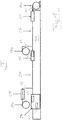
- the packaging machine shown comprises an elongated machine frame 35 which extends in a transport direction T in which the foils 11, 13, 15 used for the desired production of multi-layer packs are moved.
- the foils 11, 13, 15 are each in the form of a foil web which is fed from a supply roll 11a, 13a, 15a.
- a circulating endless transport chain (not shown) is provided in a basically known manner on both sides of the machine frame 35, which is guided on the machine frame 35 in a respective chain guide and holds the lower film 11 at an edge area.
- the lower film 11 is clamped in this way between the two transport chains spaced apart transversely to the transport direction T.
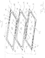
- the perforations 31 each include a plurality of gas passages 32, oval in this exemplary embodiment, which are formed in a front region of the respective film edge region 29, as seen in the transport direction T.
- the gas passages 32 can each be an opening produced by removing material, for example by punching.
- the passages 32 can each be formed without removing material, for example by cutting and then opening out a respective flap-like material section.
- the work station 21 can be saved and the length of the packaging machine can be reduced if a pre-perforated lower film 11 is used and, in addition, reshaping of the lower film is not required.
- a product to be packaged (not shown) is placed on the lower film 11.
- the product can, for example, be a portion of one or more product slices separated from a food product, for example sausage, ham or cheese, by means of a high-performance slicer.
- the transport path in which the lower film 11 is transported is fed from above a middle film 13, which has at least essentially the same web width B ( Fig. 2 ) as the lower film 11.
- the edge regions 19 of the central film 13 each have the same width as the corresponding edge region 19 of the lower film 11.
- the edge regions 19 of the central film 13 are unperforated, so that the perforations 31 of the lower film 11 each come from the corresponding edge region 19 of the Central film 13 are covered when the central film 13 lies on the lower film 11.
- the area between two superimposed product areas 17 of the lower film 11 and the upper film 13 contains the previously placed product and is also referred to as the product layer in the present disclosure. If - as shown - the lower film does not have any depressions produced by forming, these product layers are not chambers or compartments with a receiving volume determined by the forming, but rather only around areas between the lower film 11 and the upper film 13 in which a product is located.
- the lateral, front and rear boundaries of the product layers are each defined by a circumferential end seal 37, which will be discussed in more detail below.
- each film is often a composite of a plurality of individual film layers connected to one another, one on top of the other, which have different functions and therefore have different properties and / or can consist of different materials.
- each of these individual layers is not necessarily melted, but rather only one outer film layer, for example.
- a lower evacuation and / or gassing tool 41 which is explained in more detail below, is on the one hand a lower evacuation and / or gas supply tool 41 of a sealing station 29 explained in more detail below and the sealing tool 43 of the sealing station 25, on the other hand, arranged offset from one another in the transport direction T and each shorter than a pack length L ( Fig. 2 ).
- the length of each of these tools 43, 41 is only about half the length of a pack L. Consequently, the sealing station 25 only needs to be about half the length of a pack length L.
- the packaging machine does not require any additional means of transport and, in particular, no transport chains, as are provided for the lower film 11, since the sealing of the central film 13 to the lower film 11 explained above, both for reliable transport of the central film 13 and for always correct transport Alignment of the central film 13 relative to the lower film 11 ensures.
- the middle film 13 thus forms an upper product layer between the two product areas 17, which contains the previously placed upper product.
- FIG. 1 A work station 28 is arranged in the feed path of the upper film 15, in which a perforation 31 is made in each of the edge areas 19 of the upper film 15 ( Fig. 2 ).
- the perforations 31 of the upper film 15 can be identical in size, shape and position to the perforations 31 of the lower film 11. But this is not mandatory.
- the perforations 31 of the upper film 15 - in contrast to the lower film 11 - are each formed in a rear region of the respective edge region 19, as seen in the transport direction T.
- the perforations 31 of the upper film 15 are consequently, viewed in the transport direction T, arranged offset with respect to the perforations 31 of the lower film 11, the perforations 31 of the upper film 15 being located do not overlap with the perforations 31 of the lower film 11.
- the perforations 31 of the upper film 15 overlap with the seals 33 of the central film 13.
- all perforations 31 and seals 33 of the left edge areas 19, seen in transport direction T, and all perforations 31 and seals 33 of right edge areas 19, seen in transport direction T, are each located on a common working line W running parallel to transport direction T.
- the left working line W is indicated in all three foils 11, 13 and 15 by a dashed line, while the right working line W is indicated by a dash-dotted line.
- the lower product layer between the middle film 13 and the lower film 17 and the upper product layer between the middle film 13 and the upper film 15 are simultaneously subjected to a gas exchange by first evacuating the product layers and then applying a protective gas.
- a gas exchange by first evacuating the product layers and then applying a protective gas.
- the tools 41, 45 for evacuating and gassing the product layers are aligned with the respective gas outlets 32 of the lower film 11 and the upper film 15 in terms of their position transverse to the transport direction T and in relation to a respective pack P in the transport direction T.
- These tools 41, 45 can each be nozzles which are each aligned with one of the gas passages 32.
- the sealing station 29 comprises a sealing tool, not shown, which is designed in a basically known manner to connect all three foils 11, 13 and 15 to one another by forming an end seal 37 that runs around the product areas 17 of the foils and thereby the lower product layer and the to close the upper product layer in a gastight manner.
- the lateral areas of the end seal 37 lie within the edge areas 19 of the foils 11, 13, 15.
- the sections of the edge areas 19 lying outside the end seal 37 are separated downstream of the sealing station 29, optionally before or after the packs P are labeled.
- the seals 33 and the perforations 31 are no longer present on the final packs, as they will be commercially available for example later.
- the packaging machine according to the invention works in cycles. In each work cycle, the foils 11, 13 and 15 are moved together by one working length in the transport direction T, the working length of the packaging machine corresponding to the format length already mentioned at the beginning, i.e. at least one pack length L.
- the packaging machine can produce the packs P in one or more lanes.
- the upper film 11, the central film 13 and the upper film 15 can each be formed by a separate film web for each of the tracks running parallel next to one another in the transport direction T.
- all tracks can have a common lower film 11, a common central film 13 and also a have common upper film 15.
- the tools of the individual work stations are designed in such a way that between two adjacent tracks the edge regions 19 according to FIG Fig. 2 corresponding areas can be provided with the perforations 31 or seals 33.
- each unperforated middle foils can be fed in one after the other. This consequently results in at least one product layer that is delimited neither by the lower film 11 nor by the upper film 15, but rather by two unperforated central films.
- a certain gas exchange can also take place from the side between the foils lying on top of one another.
- this product layer can optionally be used for products for which a gas exchange is not absolutely necessary and generally dispensable, for example for small packaging of additives such as mustard or dry spices (e.g. salt and pepper), for napkins, cutlery and / or toothpicks or for product information, advertising flyers, raffle tickets, etc.
Landscapes
- Engineering & Computer Science (AREA)
- Mechanical Engineering (AREA)
- Chemical & Material Sciences (AREA)
- Dispersion Chemistry (AREA)
- Containers And Plastic Fillers For Packaging (AREA)
Claims (15)
- Machine d'emballage, en particulier pour produits alimentaires, destinée de préférence pour la mise en œuvre d'un procédé selon l'une des revendications 9 à 21, comportant plusieurs postes de travail disposés les uns derrière les autres le long d'une direction de transport (T) et destinés à la fabrication d'emballages multicouches (P) à partir d'une feuille inférieure (11), d'une feuille supérieure (15) et d'au moins une feuille centrale (13) interposée,
dans laquelle
la feuille inférieure (11) entoure avec la feuille centrale (13) une couche à produit inférieure, et la feuille supérieure (15) entoure avec la ou une autre feuille centrale (13) une couche à produit supérieure d'un emballage respectif (P),
les feuilles présentent chacune une zone à produit (17) et des zones de bord (19) s'étendant latéralement à côté de la zone à produit (17) parallèlement à la direction de transport (T),
un poste de travail est un poste de scellage (29) qui est réalisé pour solliciter les couches à produit avec un vide et/ou avec un gaz à travers des perforations (31) prévues dans les zones de bord (19) de la feuille supérieure (15) et de la feuille inférieure (11) et ensuite pour les fermer en scellant les feuilles,
le poste de scellage (29) comprend un outil supérieur d'évacuation et/ou d'apport de gaz (45) aligné avec la perforation (31) de la feuille supérieure (15) et un outil inférieur d'évacuation et/ou d'apport de gaz (41) aligné avec la perforation (31) de la feuille inférieure (11),
un autre poste de travail est un poste d'attachement (25) qui est situé en amont du poste de scellage (29) et qui est réalisé pour attacher la feuille centrale (13) à la feuille inférieure (11) au niveau d'une attache (33) située dans les zones de bord (19), et
l'outil inférieur d'évacuation et/ou d'apport de gaz (41) du poste de scellage (29) et un outil d'attachement (43) du poste d'attachement (25) servant à produire l'attache (33) se trouvent sur une ligne de travail commune (W) s'étendant parallèlement à la direction de transport (T). - Machine d'emballage selon la revendication 1,
dans laquelle
par rapport à un emballage respectif (P), l'outil inférieur d'évacuation et/ou d'apport de gaz (41) et l'outil d'attachement (43) ne se chevauchent pas dans la direction de transport (T). - Machine d'emballage selon la revendication 1 ou 2,
dans laquelle
la machine d'emballage peut fonctionner en cycles,
dans un cycle respectif, les feuilles peuvent être déplacées dans la direction de transport (T) d'une longueur de travail correspondant à au moins une longueur d'emballage (L), et
en particulier, par rapport à un emballage respectif (P), l'outil inférieur et/ou supérieur d'évacuation et/ou d'apport de gaz (41, 45) d'une part et l'outil d'attachement (43) d'autre part présentent chacun une longueur dans la direction de transport (T) dont la somme est inférieure à la longueur de travail. - Machine d'emballage selon l'une des revendications précédentes,
dans laquelle
l'outil supérieur d'évacuation et/ou d'apport de gaz (45) se trouve également sur la ligne de travail commune (W). - Machine d'emballage selon l'une des revendications précédentes,
dans laquelle
l'outil inférieur d'évacuation et/ou d'apport de gaz (41) et l'outil supérieur d'évacuation et/ou d'apport de gaz (45) ne se chevauchent pas dans la direction de transport (T), et/ou
par rapport à un emballage respectif (P), l'outil supérieur d'évacuation et/ou d'apport de gaz (45) et l'outil d'attachement (43) se chevauchent dans la direction de transport. - Procédé de fabrication d'emballages multicouches (P), en particulier contenant des produits alimentaires, à partir d'une feuille inférieure (11), d'une feuille supérieure (15) et d'au moins une feuille centrale (13) interposée, en particulier au moyen d'un dispositif selon l'une des revendications précédentes,
dans lequel
la feuille inférieure (11) entoure avec la feuille centrale (13) une couche à produit inférieure, et la feuille supérieure (15) entoure avec la ou une autre feuille centrale (13) une couche à produit supérieure d'un emballage respectif (P), et
les feuilles transportées le long d'une direction de transport (T) présentent chacune une zone à produit (17) et des zones de bord (19) s'étendant latéralement à côté de la zone à produit (17) parallèlement à la direction de transport (T),
procédé dans lequel les couches à produit sont sollicitées avec un vide et/ou avec un gaz à travers des perforations (31) prévues dans les zones de bord (19) de la feuille supérieure (15) et de la feuille inférieure (11) et sont ensuite fermées par scellage des feuilles,
la sollicitation avec un vide et/ou avec un gaz s'effectue pendant que la zone de bord non perforée (19) de la feuille centrale (13) et les zones de bord perforées (19) de la feuille inférieure (11) et de la feuille supérieure (15) se chevauchent, et
la couche à produit inférieure est sollicitée à travers la perforation (31) de la feuille inférieure (11), et la couche à produit supérieure est sollicitée à travers la perforation (31) de la feuille supérieure (15). - Procédé selon la revendication 6,
dans lequel
la couche à produit inférieure et la couche à produit supérieure sont sollicitées simultanément avec un vide et/ou avec un gaz, et/ou la sollicitation avec un vide et/ou avec un gaz et la fermeture s'effectuent dans un poste de scellage (29) constituant l'un des postes de travail. - Procédé selon la revendication 6 ou 7,
dans lequel
après l'alimentation de la feuille inférieure (11) et de la feuille centrale (13), la zone de bord (19) de la feuille centrale (13) est attachée à la zone de bord (19) de la feuille inférieure (11), et/ou
l'attachement s'effectue le long d'une ligne de travail (W) s'étendant parallèlement à la direction de transport (T), ligne sur laquelle se trouve(nt) au moins la perforation (31) de la feuille inférieure (11), de préférence également la perforation (31) de la feuille supérieure (15), et/ou dans un emballage respectif (P), l'attachement s'effectue dans une zone d'attachement qui ne chevauche pas avec une zone de perforation de la feuille inférieure (11) dans la direction de transport (T). - Procédé selon l'une des revendications 6 à 8,
dans lequel
la feuille inférieure (11) et la feuille supérieure (15) sont perforées non pas simultanément et/ou à différents endroits de la machine d'emballage, en particulier à des endroits espacés les uns des autres dans la direction de transport (T), et/ou
la feuille inférieure (11) et/ou la feuille supérieure (15) sont perforées pendant l'alimentation, ou
on utilise une feuille inférieure pré-perforée (11) et/ou une feuille supérieure pré-perforée (15). - Procédé selon l'une des revendications 6 à 9,
dans lequel
la feuille inférieure (11) et la feuille supérieure (15) sont perforées de telle sorte que, ou des feuilles pré-perforées de manière correspondante sont utilisées de telle sorte que dans un emballage respectif (P), les perforations (31) de la feuille inférieure (11) et de la feuille supérieure (13) ne se chevauchent pas dans la direction de transport (T). - Procédé selon l'une des revendications 6 à 10,
dans lequel
les perforations (31) présentent chacune un ou plusieurs passages de gaz (32) qui sont créés chacun soit par enlèvement de matière, soit sans enlèvement de matière, par découpe, par entaillage ou par perforation du matériau, de préférence en supplément par écartement d'une ou de plusieurs portions de matériau. - Procédé selon l'une des revendications 6 à 11,
dans lequel
la feuille inférieure (11), la feuille supérieure (15) et la feuille centrale (13) présentent chacune au moins sensiblement la même largeur de bande (B). - Utilisation d'une feuille non perforée en tant que feuille centrale (13) dans une machine d'emballage selon l'une des revendications 1 à 5 et/ou dans un procédé selon l'une des revendications 6 à 12.
- Utilisation d'au moins trois feuilles ayant au moins sensiblement la même largeur de bande en tant que feuille inférieure (11), feuille supérieure (15) et feuille centrale (13) dans une machine d'emballage selon l'une des revendications 1 à 5 et/ou dans un procédé selon l'une des revendications 6 à 12.
- Emballage multicouche,
fabriqué ou pouvant être fabriqué par une machine d'emballage selon l'une des revendications 1 à 5 et/ou obtenu ou pouvant être obtenu par un procédé selon l'une des revendications 6 à 12,
comportant une feuille inférieure (11), une feuille supérieure (15) et au moins une feuille centrale (13) interposée,
dans lequel la feuille inférieure (11) entoure avec la feuille centrale (13) une couche à produit inférieure, et la feuille supérieure (15) entoure avec la ou une autre feuille centrale (13) une couche à produit supérieure.
Applications Claiming Priority (1)
| Application Number | Priority Date | Filing Date | Title |
|---|---|---|---|
| DE102018108640.7A DE102018108640A1 (de) | 2018-04-11 | 2018-04-11 | Herstellung von mehrlagenpackungen |
Publications (2)
| Publication Number | Publication Date |
|---|---|
| EP3552979A1 EP3552979A1 (fr) | 2019-10-16 |
| EP3552979B1 true EP3552979B1 (fr) | 2021-01-06 |
Family
ID=65408964
Family Applications (1)
| Application Number | Title | Priority Date | Filing Date |
|---|---|---|---|
| EP19156456.6A Not-in-force EP3552979B1 (fr) | 2018-04-11 | 2019-02-11 | Fabrication d'emballages multicouche |
Country Status (2)
| Country | Link |
|---|---|
| EP (1) | EP3552979B1 (fr) |
| DE (1) | DE102018108640A1 (fr) |
Families Citing this family (3)
| Publication number | Priority date | Publication date | Assignee | Title |
|---|---|---|---|---|
| DE102020130654A1 (de) | 2020-11-19 | 2022-05-19 | Multivac Sepp Haggenmüller Se & Co. Kg | Verpackungsvorrichtung |
| DE102021103685A1 (de) | 2020-12-11 | 2022-06-15 | Weber Maschinenbau Gmbh Breidenbach | Siegelstation |
| EP4011603B1 (fr) | 2020-12-11 | 2024-10-09 | Weber Food Technology GmbH | Station de scellage |
Family Cites Families (6)
| Publication number | Priority date | Publication date | Assignee | Title |
|---|---|---|---|---|
| US3481100A (en) * | 1966-11-23 | 1969-12-02 | Anderson Bros Mfg Co | Method and apparatus for packaging in protective atmosphere |
| GB2041318B (en) * | 1979-02-14 | 1983-05-25 | Oordt & Co Holding Bv | Double-walled air-tight package and a method of manufacturing such a package |
| WO1988000907A1 (fr) * | 1986-08-04 | 1988-02-11 | Garwood Limited | Emballage |
| DE102005048491B4 (de) | 2005-10-07 | 2008-04-17 | Variovac Ps Systempack Gmbh | Verpackungsmaschine zur Herstellung von Mehrlagenfolienverpackungen und deren Verwendung |
| DE102011010601B4 (de) | 2011-02-08 | 2013-09-05 | Multivac Sepp Haggenmüller Gmbh & Co. Kg | Verpackungsmaschine zum Herstellen einer Mehrlagenpackung |
| WO2013083834A1 (fr) * | 2011-12-09 | 2013-06-13 | Gea Cfs Germany Gmbh | Machine d'emballage pourvue d'un outil combiné de formage et de scellement |
-
2018
- 2018-04-11 DE DE102018108640.7A patent/DE102018108640A1/de not_active Withdrawn
-
2019
- 2019-02-11 EP EP19156456.6A patent/EP3552979B1/fr not_active Not-in-force
Non-Patent Citations (1)
| Title |
|---|
| None * |
Also Published As
| Publication number | Publication date |
|---|---|
| DE102018108640A1 (de) | 2019-10-17 |
| EP3552979A1 (fr) | 2019-10-16 |
Similar Documents
| Publication | Publication Date | Title |
|---|---|---|
| EP1255681B1 (fr) | Film etirable et procede de fabrication d'un film etirable | |
| EP1598276B1 (fr) | Machine d' emballage et procédé pour découper des emballages. | |
| EP2484594B1 (fr) | Machine d'emballage pour la fabrication d'un emballage en plusieurs couches | |
| EP2004491B1 (fr) | Procédé de fabrication d'un emballage et machine à emballer | |
| EP3552979B1 (fr) | Fabrication d'emballages multicouche | |
| EP0718096A2 (fr) | Méthode et appareil de fabrication d'un récipient pour boissons | |
| EP1320495A1 (fr) | Corps de remplissage remplis de gaz | |
| EP2288559A1 (fr) | Équipement et procédé de production de découpes à partir d'une bande de film | |
| WO2013110379A1 (fr) | Procédé et dispositif destinés à relier deux extrémités de bandes métalliques | |
| EP2621430B1 (fr) | Procedure d'emballage de produits et installation pour la realisation de la procedure | |
| EP2123585B1 (fr) | Procédé et dispositif de traitement d'une bande de matériau déplacée imprimée | |
| EP4070936B1 (fr) | Machine d'emballage par emboutissage pourvu de rails de scellage par impulsion et procédé de scellage par impulsion | |
| EP1539583B1 (fr) | Procede et dispositif pour produire un conditionnement individuel primaire d'un cachet | |
| DE602005002729T2 (de) | Verpackung mit mindestens einer Tasche | |
| EP1797974A2 (fr) | Méthode de fabrication d'une traverse, en particulier pour véhicule automobile | |
| EP3733528B1 (fr) | Outil de scellage et procédé de scellage de barquettes | |
| EP3967637B1 (fr) | Dispositif et procédé d'épissurage et de fourniture continue d'une bande continue de feuille | |
| EP3663080B1 (fr) | Procédé et dispositif de fabrication de sachets en feuille | |
| DE102019124008B4 (de) | Technik zum Ausschneiden von in einer Folie erzeugten Verpackungen | |
| DE19822269A1 (de) | Beutel aus thermoplastischer Kunststoffolie sowie Verfahren und Vorrichtung zum Herstellen eines solchen Beutels | |
| DE19740831A1 (de) | Vorrichtung zum Anbringen von Aufreißlaschen | |
| DE2753451A1 (de) | Doppellagiges folienband | |
| DE2921109C2 (de) | Verpackungsvorrichtung mit einer Aufwickeleinrichtung für die Folienabfallstreifen | |
| EP4045419B1 (fr) | Sac, procédé et dispositif de fabrication d'un sac | |
| EP4327995A1 (fr) | Machine d'emballage par emboutissage et procédé de fabrication d'un trou |
Legal Events
| Date | Code | Title | Description |
|---|---|---|---|
| PUAI | Public reference made under article 153(3) epc to a published international application that has entered the european phase |
Free format text: ORIGINAL CODE: 0009012 |
|
| STAA | Information on the status of an ep patent application or granted ep patent |
Free format text: STATUS: REQUEST FOR EXAMINATION WAS MADE |
|
| 17P | Request for examination filed |
Effective date: 20190731 |
|
| AK | Designated contracting states |
Kind code of ref document: A1 Designated state(s): AL AT BE BG CH CY CZ DE DK EE ES FI FR GB GR HR HU IE IS IT LI LT LU LV MC MK MT NL NO PL PT RO RS SE SI SK SM TR |
|
| AX | Request for extension of the european patent |
Extension state: BA ME |
|
| STAA | Information on the status of an ep patent application or granted ep patent |
Free format text: STATUS: EXAMINATION IS IN PROGRESS |
|
| 17Q | First examination report despatched |
Effective date: 20200123 |
|
| GRAP | Despatch of communication of intention to grant a patent |
Free format text: ORIGINAL CODE: EPIDOSNIGR1 |
|
| STAA | Information on the status of an ep patent application or granted ep patent |
Free format text: STATUS: GRANT OF PATENT IS INTENDED |
|
| INTG | Intention to grant announced |
Effective date: 20200810 |
|
| GRAS | Grant fee paid |
Free format text: ORIGINAL CODE: EPIDOSNIGR3 |
|
| GRAA | (expected) grant |
Free format text: ORIGINAL CODE: 0009210 |
|
| STAA | Information on the status of an ep patent application or granted ep patent |
Free format text: STATUS: THE PATENT HAS BEEN GRANTED |
|
| AK | Designated contracting states |
Kind code of ref document: B1 Designated state(s): AL AT BE BG CH CY CZ DE DK EE ES FI FR GB GR HR HU IE IS IT LI LT LU LV MC MK MT NL NO PL PT RO RS SE SI SK SM TR |
|
| REG | Reference to a national code |
Ref country code: GB Ref legal event code: FG4D Free format text: NOT ENGLISH |
|
| REG | Reference to a national code |
Ref country code: AT Ref legal event code: REF Ref document number: 1352091 Country of ref document: AT Kind code of ref document: T Effective date: 20210115 Ref country code: CH Ref legal event code: EP |
|
| REG | Reference to a national code |
Ref country code: DE Ref legal event code: R096 Ref document number: 502019000624 Country of ref document: DE |
|
| REG | Reference to a national code |
Ref country code: IE Ref legal event code: FG4D Free format text: LANGUAGE OF EP DOCUMENT: GERMAN |
|
| REG | Reference to a national code |
Ref country code: NL Ref legal event code: MP Effective date: 20210106 |
|
| REG | Reference to a national code |
Ref country code: LT Ref legal event code: MG9D |
|
| PG25 | Lapsed in a contracting state [announced via postgrant information from national office to epo] |
Ref country code: LT Free format text: LAPSE BECAUSE OF FAILURE TO SUBMIT A TRANSLATION OF THE DESCRIPTION OR TO PAY THE FEE WITHIN THE PRESCRIBED TIME-LIMIT Effective date: 20210106 Ref country code: PT Free format text: LAPSE BECAUSE OF FAILURE TO SUBMIT A TRANSLATION OF THE DESCRIPTION OR TO PAY THE FEE WITHIN THE PRESCRIBED TIME-LIMIT Effective date: 20210506 Ref country code: NO Free format text: LAPSE BECAUSE OF FAILURE TO SUBMIT A TRANSLATION OF THE DESCRIPTION OR TO PAY THE FEE WITHIN THE PRESCRIBED TIME-LIMIT Effective date: 20210406 Ref country code: GR Free format text: LAPSE BECAUSE OF FAILURE TO SUBMIT A TRANSLATION OF THE DESCRIPTION OR TO PAY THE FEE WITHIN THE PRESCRIBED TIME-LIMIT Effective date: 20210407 Ref country code: FI Free format text: LAPSE BECAUSE OF FAILURE TO SUBMIT A TRANSLATION OF THE DESCRIPTION OR TO PAY THE FEE WITHIN THE PRESCRIBED TIME-LIMIT Effective date: 20210106 Ref country code: HR Free format text: LAPSE BECAUSE OF FAILURE TO SUBMIT A TRANSLATION OF THE DESCRIPTION OR TO PAY THE FEE WITHIN THE PRESCRIBED TIME-LIMIT Effective date: 20210106 Ref country code: BG Free format text: LAPSE BECAUSE OF FAILURE TO SUBMIT A TRANSLATION OF THE DESCRIPTION OR TO PAY THE FEE WITHIN THE PRESCRIBED TIME-LIMIT Effective date: 20210406 |
|
| PG25 | Lapsed in a contracting state [announced via postgrant information from national office to epo] |
Ref country code: SE Free format text: LAPSE BECAUSE OF FAILURE TO SUBMIT A TRANSLATION OF THE DESCRIPTION OR TO PAY THE FEE WITHIN THE PRESCRIBED TIME-LIMIT Effective date: 20210106 Ref country code: LV Free format text: LAPSE BECAUSE OF FAILURE TO SUBMIT A TRANSLATION OF THE DESCRIPTION OR TO PAY THE FEE WITHIN THE PRESCRIBED TIME-LIMIT Effective date: 20210106 Ref country code: RS Free format text: LAPSE BECAUSE OF FAILURE TO SUBMIT A TRANSLATION OF THE DESCRIPTION OR TO PAY THE FEE WITHIN THE PRESCRIBED TIME-LIMIT Effective date: 20210106 Ref country code: PL Free format text: LAPSE BECAUSE OF FAILURE TO SUBMIT A TRANSLATION OF THE DESCRIPTION OR TO PAY THE FEE WITHIN THE PRESCRIBED TIME-LIMIT Effective date: 20210106 |
|
| PG25 | Lapsed in a contracting state [announced via postgrant information from national office to epo] |
Ref country code: IS Free format text: LAPSE BECAUSE OF FAILURE TO SUBMIT A TRANSLATION OF THE DESCRIPTION OR TO PAY THE FEE WITHIN THE PRESCRIBED TIME-LIMIT Effective date: 20210506 |
|
| REG | Reference to a national code |
Ref country code: DE Ref legal event code: R097 Ref document number: 502019000624 Country of ref document: DE |
|
| REG | Reference to a national code |
Ref country code: BE Ref legal event code: MM Effective date: 20210228 |
|
| PG25 | Lapsed in a contracting state [announced via postgrant information from national office to epo] |
Ref country code: SM Free format text: LAPSE BECAUSE OF FAILURE TO SUBMIT A TRANSLATION OF THE DESCRIPTION OR TO PAY THE FEE WITHIN THE PRESCRIBED TIME-LIMIT Effective date: 20210106 Ref country code: CZ Free format text: LAPSE BECAUSE OF FAILURE TO SUBMIT A TRANSLATION OF THE DESCRIPTION OR TO PAY THE FEE WITHIN THE PRESCRIBED TIME-LIMIT Effective date: 20210106 Ref country code: EE Free format text: LAPSE BECAUSE OF FAILURE TO SUBMIT A TRANSLATION OF THE DESCRIPTION OR TO PAY THE FEE WITHIN THE PRESCRIBED TIME-LIMIT Effective date: 20210106 Ref country code: LU Free format text: LAPSE BECAUSE OF NON-PAYMENT OF DUE FEES Effective date: 20210211 Ref country code: MC Free format text: LAPSE BECAUSE OF FAILURE TO SUBMIT A TRANSLATION OF THE DESCRIPTION OR TO PAY THE FEE WITHIN THE PRESCRIBED TIME-LIMIT Effective date: 20210106 |
|
| PLBE | No opposition filed within time limit |
Free format text: ORIGINAL CODE: 0009261 |
|
| STAA | Information on the status of an ep patent application or granted ep patent |
Free format text: STATUS: NO OPPOSITION FILED WITHIN TIME LIMIT |
|
| PG25 | Lapsed in a contracting state [announced via postgrant information from national office to epo] |
Ref country code: DK Free format text: LAPSE BECAUSE OF FAILURE TO SUBMIT A TRANSLATION OF THE DESCRIPTION OR TO PAY THE FEE WITHIN THE PRESCRIBED TIME-LIMIT Effective date: 20210106 Ref country code: RO Free format text: LAPSE BECAUSE OF FAILURE TO SUBMIT A TRANSLATION OF THE DESCRIPTION OR TO PAY THE FEE WITHIN THE PRESCRIBED TIME-LIMIT Effective date: 20210106 Ref country code: SK Free format text: LAPSE BECAUSE OF FAILURE TO SUBMIT A TRANSLATION OF THE DESCRIPTION OR TO PAY THE FEE WITHIN THE PRESCRIBED TIME-LIMIT Effective date: 20210106 |
|
| 26N | No opposition filed |
Effective date: 20211007 |
|
| PG25 | Lapsed in a contracting state [announced via postgrant information from national office to epo] |
Ref country code: ES Free format text: LAPSE BECAUSE OF FAILURE TO SUBMIT A TRANSLATION OF THE DESCRIPTION OR TO PAY THE FEE WITHIN THE PRESCRIBED TIME-LIMIT Effective date: 20210106 Ref country code: AL Free format text: LAPSE BECAUSE OF FAILURE TO SUBMIT A TRANSLATION OF THE DESCRIPTION OR TO PAY THE FEE WITHIN THE PRESCRIBED TIME-LIMIT Effective date: 20210106 Ref country code: IE Free format text: LAPSE BECAUSE OF NON-PAYMENT OF DUE FEES Effective date: 20210211 Ref country code: FR Free format text: LAPSE BECAUSE OF NON-PAYMENT OF DUE FEES Effective date: 20210306 |
|
| PG25 | Lapsed in a contracting state [announced via postgrant information from national office to epo] |
Ref country code: SI Free format text: LAPSE BECAUSE OF FAILURE TO SUBMIT A TRANSLATION OF THE DESCRIPTION OR TO PAY THE FEE WITHIN THE PRESCRIBED TIME-LIMIT Effective date: 20210106 |
|
| PG25 | Lapsed in a contracting state [announced via postgrant information from national office to epo] |
Ref country code: IT Free format text: LAPSE BECAUSE OF FAILURE TO SUBMIT A TRANSLATION OF THE DESCRIPTION OR TO PAY THE FEE WITHIN THE PRESCRIBED TIME-LIMIT Effective date: 20210106 |
|
| PG25 | Lapsed in a contracting state [announced via postgrant information from national office to epo] |
Ref country code: IS Free format text: LAPSE BECAUSE OF FAILURE TO SUBMIT A TRANSLATION OF THE DESCRIPTION OR TO PAY THE FEE WITHIN THE PRESCRIBED TIME-LIMIT Effective date: 20210506 |
|
| PG25 | Lapsed in a contracting state [announced via postgrant information from national office to epo] |
Ref country code: BE Free format text: LAPSE BECAUSE OF NON-PAYMENT OF DUE FEES Effective date: 20210228 |
|
| REG | Reference to a national code |
Ref country code: CH Ref legal event code: PL |
|
| PG25 | Lapsed in a contracting state [announced via postgrant information from national office to epo] |
Ref country code: LI Free format text: LAPSE BECAUSE OF NON-PAYMENT OF DUE FEES Effective date: 20220228 Ref country code: CH Free format text: LAPSE BECAUSE OF NON-PAYMENT OF DUE FEES Effective date: 20220228 |
|
| PGFP | Annual fee paid to national office [announced via postgrant information from national office to epo] |
Ref country code: DE Payment date: 20230216 Year of fee payment: 5 |
|
| P01 | Opt-out of the competence of the unified patent court (upc) registered |
Effective date: 20230522 |
|
| PG25 | Lapsed in a contracting state [announced via postgrant information from national office to epo] |
Ref country code: NL Free format text: LAPSE BECAUSE OF NON-PAYMENT OF DUE FEES Effective date: 20210206 Ref country code: CY Free format text: LAPSE BECAUSE OF FAILURE TO SUBMIT A TRANSLATION OF THE DESCRIPTION OR TO PAY THE FEE WITHIN THE PRESCRIBED TIME-LIMIT Effective date: 20210106 |
|
| PG25 | Lapsed in a contracting state [announced via postgrant information from national office to epo] |
Ref country code: HU Free format text: LAPSE BECAUSE OF FAILURE TO SUBMIT A TRANSLATION OF THE DESCRIPTION OR TO PAY THE FEE WITHIN THE PRESCRIBED TIME-LIMIT; INVALID AB INITIO Effective date: 20190211 |
|
| GBPC | Gb: european patent ceased through non-payment of renewal fee |
Effective date: 20230211 |
|
| PG25 | Lapsed in a contracting state [announced via postgrant information from national office to epo] |
Ref country code: GB Free format text: LAPSE BECAUSE OF NON-PAYMENT OF DUE FEES Effective date: 20230211 |
|
| PG25 | Lapsed in a contracting state [announced via postgrant information from national office to epo] |
Ref country code: GB Free format text: LAPSE BECAUSE OF NON-PAYMENT OF DUE FEES Effective date: 20230211 |
|
| PG25 | Lapsed in a contracting state [announced via postgrant information from national office to epo] |
Ref country code: MK Free format text: LAPSE BECAUSE OF FAILURE TO SUBMIT A TRANSLATION OF THE DESCRIPTION OR TO PAY THE FEE WITHIN THE PRESCRIBED TIME-LIMIT Effective date: 20210106 |
|
| PG25 | Lapsed in a contracting state [announced via postgrant information from national office to epo] |
Ref country code: TR Free format text: LAPSE BECAUSE OF FAILURE TO SUBMIT A TRANSLATION OF THE DESCRIPTION OR TO PAY THE FEE WITHIN THE PRESCRIBED TIME-LIMIT Effective date: 20210106 |
|
| REG | Reference to a national code |
Ref country code: DE Ref legal event code: R119 Ref document number: 502019000624 Country of ref document: DE |
|
| PG25 | Lapsed in a contracting state [announced via postgrant information from national office to epo] |
Ref country code: MT Free format text: LAPSE BECAUSE OF FAILURE TO SUBMIT A TRANSLATION OF THE DESCRIPTION OR TO PAY THE FEE WITHIN THE PRESCRIBED TIME-LIMIT Effective date: 20210106 |
|
| PG25 | Lapsed in a contracting state [announced via postgrant information from national office to epo] |
Ref country code: DE Free format text: LAPSE BECAUSE OF NON-PAYMENT OF DUE FEES Effective date: 20240903 |
|
| PG25 | Lapsed in a contracting state [announced via postgrant information from national office to epo] |
Ref country code: DE Free format text: LAPSE BECAUSE OF NON-PAYMENT OF DUE FEES Effective date: 20240903 |
|
| REG | Reference to a national code |
Ref country code: AT Ref legal event code: MM01 Ref document number: 1352091 Country of ref document: AT Kind code of ref document: T Effective date: 20240211 |
|
| PG25 | Lapsed in a contracting state [announced via postgrant information from national office to epo] |
Ref country code: AT Free format text: LAPSE BECAUSE OF NON-PAYMENT OF DUE FEES Effective date: 20240211 |
|
| PGFP | Annual fee paid to national office [announced via postgrant information from national office to epo] |
Ref country code: AT Payment date: 20260410 Year of fee payment: 5 |