EP3678878B1 - Véhicule à moteur avec un dispositif de sortie d'air pour un intérieur du véhicule à moteur - Google Patents
Véhicule à moteur avec un dispositif de sortie d'air pour un intérieur du véhicule à moteur Download PDFInfo
- Publication number
- EP3678878B1 EP3678878B1 EP18729891.4A EP18729891A EP3678878B1 EP 3678878 B1 EP3678878 B1 EP 3678878B1 EP 18729891 A EP18729891 A EP 18729891A EP 3678878 B1 EP3678878 B1 EP 3678878B1
- Authority
- EP
- European Patent Office
- Prior art keywords
- motor vehicle
- regulating
- regulating element
- control unit
- air outlet
- Prior art date
- Legal status (The legal status is an assumption and is not a legal conclusion. Google has not performed a legal analysis and makes no representation as to the accuracy of the status listed.)
- Active
Links
Images


Classifications
-
- B—PERFORMING OPERATIONS; TRANSPORTING
- B60—VEHICLES IN GENERAL
- B60H—ARRANGEMENTS OF HEATING, COOLING, VENTILATING OR OTHER AIR-TREATING DEVICES SPECIALLY ADAPTED FOR PASSENGER OR GOODS SPACES OF VEHICLES
- B60H1/00—Heating, cooling or ventilating devices
- B60H1/34—Nozzles; Air-diffusers
- B60H1/3414—Nozzles; Air-diffusers with means for adjusting the air stream direction
-
- B—PERFORMING OPERATIONS; TRANSPORTING
- B60—VEHICLES IN GENERAL
- B60H—ARRANGEMENTS OF HEATING, COOLING, VENTILATING OR OTHER AIR-TREATING DEVICES SPECIALLY ADAPTED FOR PASSENGER OR GOODS SPACES OF VEHICLES
- B60H1/00—Heating, cooling or ventilating devices
- B60H1/00642—Control systems or circuits; Control members or indication devices for heating, cooling or ventilating devices
- B60H1/00985—Control systems or circuits characterised by display or indicating devices, e.g. voice simulators
-
- B—PERFORMING OPERATIONS; TRANSPORTING
- B60—VEHICLES IN GENERAL
- B60H—ARRANGEMENTS OF HEATING, COOLING, VENTILATING OR OTHER AIR-TREATING DEVICES SPECIALLY ADAPTED FOR PASSENGER OR GOODS SPACES OF VEHICLES
- B60H1/00—Heating, cooling or ventilating devices
- B60H1/00642—Control systems or circuits; Control members or indication devices for heating, cooling or ventilating devices
- B60H1/00814—Control systems or circuits characterised by their output, for controlling particular components of the heating, cooling or ventilating installation
- B60H1/00821—Control systems or circuits characterised by their output, for controlling particular components of the heating, cooling or ventilating installation the components being ventilating, air admitting or air distributing devices
-
- B—PERFORMING OPERATIONS; TRANSPORTING
- B60—VEHICLES IN GENERAL
- B60H—ARRANGEMENTS OF HEATING, COOLING, VENTILATING OR OTHER AIR-TREATING DEVICES SPECIALLY ADAPTED FOR PASSENGER OR GOODS SPACES OF VEHICLES
- B60H1/00—Heating, cooling or ventilating devices
- B60H1/24—Ventilating devices where the heating or cooling is irrelevant
- B60H1/241—Ventilating devices where the heating or cooling is irrelevant characterised by the location of ventilation devices in the vehicle
- B60H1/242—Ventilating devices where the heating or cooling is irrelevant characterised by the location of ventilation devices in the vehicle located in the front area
-
- B—PERFORMING OPERATIONS; TRANSPORTING
- B60—VEHICLES IN GENERAL
- B60K—ARRANGEMENT OR MOUNTING OF PROPULSION UNITS OR OF TRANSMISSIONS IN VEHICLES; ARRANGEMENT OR MOUNTING OF PLURAL DIVERSE PRIME-MOVERS IN VEHICLES; AUXILIARY DRIVES FOR VEHICLES; INSTRUMENTATION OR DASHBOARDS FOR VEHICLES; ARRANGEMENTS IN CONNECTION WITH COOLING, AIR INTAKE, GAS EXHAUST OR FUEL SUPPLY OF PROPULSION UNITS IN VEHICLES
- B60K35/00—Instruments specially adapted for vehicles; Arrangement of instruments in or on vehicles
- B60K35/60—Instruments characterised by their location or relative disposition in or on vehicles
-
- B—PERFORMING OPERATIONS; TRANSPORTING
- B60—VEHICLES IN GENERAL
- B60K—ARRANGEMENT OR MOUNTING OF PROPULSION UNITS OR OF TRANSMISSIONS IN VEHICLES; ARRANGEMENT OR MOUNTING OF PLURAL DIVERSE PRIME-MOVERS IN VEHICLES; AUXILIARY DRIVES FOR VEHICLES; INSTRUMENTATION OR DASHBOARDS FOR VEHICLES; ARRANGEMENTS IN CONNECTION WITH COOLING, AIR INTAKE, GAS EXHAUST OR FUEL SUPPLY OF PROPULSION UNITS IN VEHICLES
- B60K37/00—Dashboards
- B60K37/20—Dashboard panels
-
- B—PERFORMING OPERATIONS; TRANSPORTING
- B60—VEHICLES IN GENERAL
- B60H—ARRANGEMENTS OF HEATING, COOLING, VENTILATING OR OTHER AIR-TREATING DEVICES SPECIALLY ADAPTED FOR PASSENGER OR GOODS SPACES OF VEHICLES
- B60H1/00—Heating, cooling or ventilating devices
- B60H1/00642—Control systems or circuits; Control members or indication devices for heating, cooling or ventilating devices
- B60H1/00735—Control systems or circuits characterised by their input, i.e. by the detection, measurement or calculation of particular conditions, e.g. signal treatment, dynamic models
- B60H1/00742—Control systems or circuits characterised by their input, i.e. by the detection, measurement or calculation of particular conditions, e.g. signal treatment, dynamic models by detection of the vehicle occupants' presence; by detection of conditions relating to the body of occupants, e.g. using radiant heat detectors
-
- B—PERFORMING OPERATIONS; TRANSPORTING
- B60—VEHICLES IN GENERAL
- B60H—ARRANGEMENTS OF HEATING, COOLING, VENTILATING OR OTHER AIR-TREATING DEVICES SPECIALLY ADAPTED FOR PASSENGER OR GOODS SPACES OF VEHICLES
- B60H1/00—Heating, cooling or ventilating devices
- B60H1/00007—Combined heating, ventilating, or cooling devices
- B60H1/00207—Combined heating, ventilating, or cooling devices characterised by the position of the HVAC devices with respect to the passenger compartment
- B60H2001/00214—Devices in front of the passenger compartment
-
- B—PERFORMING OPERATIONS; TRANSPORTING
- B60—VEHICLES IN GENERAL
- B60H—ARRANGEMENTS OF HEATING, COOLING, VENTILATING OR OTHER AIR-TREATING DEVICES SPECIALLY ADAPTED FOR PASSENGER OR GOODS SPACES OF VEHICLES
- B60H1/00—Heating, cooling or ventilating devices
- B60H1/34—Nozzles; Air-diffusers
- B60H2001/3471—Details of actuators
Definitions
- the invention relates to a motor vehicle with an air outlet device for an interior of the motor vehicle.
- Motor vehicles generally have one or more air outlets for air conditioning vehicle interiors, which allow the direction and intensity of an air flow to be adjusted, for example by means of mechanically connected tabs.
- Such systems are known, for example, from DE 102 58 955 A1 , the WO 2016/157791A1 or the DE 299 15 938 U1
- Such tabs usually allow limited mechanical control of air flows in localized areas and also do not adequately meet the aesthetic requirements of many vehicle owners.
- the motor vehicle comprises an air outlet device for its interior with a first and a second ventilation gap, which are arranged at a distance from one another.
- the air outlet device further comprises a decorative element which is coupled to an instrument panel of the motor vehicle and which is arranged between the first and the second ventilation gap.
- the air outlet device further comprises an operating unit which is coupled to the decorative element and which has a first regulating element and a second regulating element, wherein an intensity of an air flow through at least one of the ventilation gaps can be adjusted independently of one another by means of the first regulating element and an orientation of the air flow through at least one of the ventilation gaps can be adjusted independently of one another by means of the second regulating element.
- the described air outlet device enables simple and convenient operation of hidden air outlets, such as register outlets.
- a register vent is a hidden, electrified air vent that can be controlled electronically and whose air flow properties can be adjusted using two slightly aligned, laminar individual flows. The resulting total flow is determined depending on the speed differences of the two individual flows. in different directions and can enter the interior of the motor vehicle through the first and/or second ventilation gap.
- an electronic display operating concept can be implemented, which is particularly useful for electrified air outlets, such as register outlets, since such air outlets are generally not designed to be directly adjustable and their current operating status is not directly displayed.
- the decorative element faces the interior of the motor vehicle and realizes a cladding for covering a section of the air outlet device, for example to conceal a flap mechanism that is arranged to control the air flow in an air duct of the air outlet device.
- the decorative element is arranged such that it delimits a bottom side of the first ventilation gap and a top side of the second ventilation gap, wherein the first ventilation gap realizes an upper ventilation access and the second ventilation gap realizes a lower ventilation access to the interior of the motor vehicle with respect to a vertical of the operational motor vehicle.
- the decorative element meets functional requirements and also an aesthetic aspect and contributes to the comfort of the motor vehicle.
- the first and the second regulating element each have a touch-sensitive surface element which is integrated in the decorative element.
- the air outlet device comprises a Control unit which is coupled to the first and second regulating elements by means of signals, so that a position of an object on one of the touch-sensitive surface elements of the first and/or second regulating element can be determined by means of the control unit and the air flow can thus be electrically controlled by means of the regulating elements.
- the two control elements each have a capacitive operating display with a light source, which is integrated in the decorative element and by means of which the air flow can be controlled electrically.
- a capacitive 2D sensor system enables convenient control of the air flow of the air outlet device according to a touchpad and can also be arranged hidden in the decorative element.
- a changed setting of the air flow is implemented by means of the control unit via servomotors on the air outlet, which are coupled, for example, to a folding mechanism of air control flaps.
- the decorative element is designed, for example, as a partially translucent wooden element in which the control elements including the operating display and lighting are embedded.
- a respective operating display with lighting is designed as a touch-sensitive, high-resolution pixel matrix that is arranged below a surface of the decorative element that faces the interior of the motor vehicle.
- Such an operating display integrated into the decorative element, in conjunction with the control unit, enables the direction and intensity to be set and, if necessary, the desired diffusion or focusing of the air passing through the ventilation slots or ventilation gaps to be set. air flow exiting the interior.
- one or both operating displays are implemented as low-resolution segment displays, which have one or more arranged LEDs as lighting sources.
- control unit is designed to activate the respective light source of the respective operating display in an operating state in which an object is detected on one of the touch-sensitive surface elements of the first or second regulating element. For example, by touching the decorative element with a finger or a hand, an operating display can be activated and/or illuminated so that a function selection becomes visible.
- the air outlet device can advantageously comprise a positioning element which is designed to indicate a position of the first and/or second regulating element in relation to the decorative element.
- a positioning element is useful in order to enable the operating displays to be found quickly even in a non-activated or non-illuminated state.
- Such a positioning element can be arranged or designed as a marking in the form of a point or an arrow in or on the decorative element.
- the positioning element preferably has a light source and is coupled to the control unit in terms of signaling, so that the positioning element can be controlled by means of the control unit.
- the lamp of the position element is activated in a resting state in which no object or manual contact is detected on one of the touch-sensitive surface elements of the first or second control element and lights up to locate the operating displays.
- the lamp of the position element is deactivated by the control unit in order to avoid an overlap with the illuminated operating displays and to enable simple and clear setting of the desired functions of the air flow of the air outlet device.
- the positioning element can thus be implemented in particular as an illuminable location symbol which is integrated between the two partial vents or the two ventilation gaps in the decorative element and which visually indicates the operating areas of the control elements which may be hidden in the decorative element.
- the positioning element is designed, for example, as an optical button with a segmented LED display which is visible in a resting state when the control elements are not being operated. By tapping on the positioning element, the control elements or their respective operating displays can be activated and preferably illuminated and the location symbol implemented by the positioning element is deactivated.
- the air outlet device comprises a proximity sensor which is coupled to the control unit in terms of signal technology and by means of which an approach of an object to the first or second regulating element can be determined, so that the air outlet device can be operated depending on measurement signals from the proximity sensor system.
- a proximity sensor system has, for example, a capacitive sensor, an infrared LED or a gesture camera, by means of which an approach of an object to the first or second regulating element can be detected.
- a previously hidden control panel of the first and/or second control element can be activated and illuminated.
- the position element can be deactivated and the control display of the control elements illuminated when a hand approaches. If the hand moves away from the decorative element or the control panel of the control elements, the air outlet device can return to the idle state after a predetermined period of time, for example 3 seconds or 5 seconds, or deactivate the control displays of the control elements and retain the set air flow properties.
- the air outlet device comprises an object detection sensor system which is coupled to the control unit in terms of signal technology and by means of which a position of an object in the interior of the motor vehicle can be determined, so that the air outlet device can be operated depending on measurement signals from the object detection sensor system.
- object detection can be camera-based face tracking of the driver or front passenger so that a set air flow can be adjusted.
- the driver uses the control elements to set an air flow with the desired intensity, which is directed at his head in a first sitting position.
- the driver leans back, for example, so that the control unit uses the object recognition sensor to adjust the air flow and, if necessary, adjust its intensity so that the desired air flow is also directed at the driver's head in such a second sitting position.
- control unit of the air outlet device is coupled in terms of signaling to the first and second regulating elements and to a multifunctional display of the motor vehicle, so that the first and/or second regulating elements can be controlled by means of the multifunctional display and the air flow can thus be electrically adjusted by means of the regulating elements.
- a multifunctional display is designed, for example, as an LCD display in the dashboard area of the motor vehicle and, in addition to the previously described operating display of the regulating elements, enables air flow parameters to be set.
- the first and second regulating elements each have a mechanical coupling to respective air control flaps, so that the air flow can be mechanically adjusted by means of the regulating elements.
- the first regulating element comprises, for example, a rotatable ring-shaped element and the second regulating element a rotatable spherical element for mechanically adjusting the air flow, which are each in the Decorative element are integrated so that the annular element surrounds the spherical element.
- the first regulating element comprises a displaceable locking element and the second regulating element comprises a displaceable sliding element for mechanically adjusting the air flow, which are arranged in the first or second ventilation gap so that the locking element and the sliding element are arranged one above the other or next to each other.
- the air outlet device can be adjusted mechanically and the air flow entering the interior can be adapted in terms of intensity, direction and, if necessary, focusing.
- FIG 1 illustrates an embodiment of a motor vehicle 1, which comprises an air outlet device 10 for air conditioning an interior of the motor vehicle 1.
- the air outlet device 10 is coupled in terms of signaling to a control unit 3 and a multifunctional display 5 and enables, as will be explained below with reference to the Figures 2A-5 explained, a simple and reliable operating concept for air conditioning the interior and also contributes to increased comfort of the motor vehicle 1.
- a simple and convenient operation of hidden air vents, such as register vents can be realized by means of the air outlet device 10.
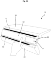
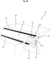
- FIGS 2A-2C show a schematic embodiment of the air outlet device 10 in perspective views, which is implemented as a register outlet.
- the air outlet device 10 can, for example, be mounted facing the driver, in the middle of a dashboard of the motor vehicle 1 or facing the windscreen of the motor vehicle 1 in an edge region of the dashboard.
- the air outlet device 10 comprises a first and a second ventilation gap 11 and 12, which are arranged at a distance from one another and, according to the illustrated embodiment, are aligned substantially parallel to one another.
- the air outlet device 10 further comprises a decorative element 13 which is coupled to a dashboard panel 20 for the motor vehicle 1 and which is arranged between the first and the second ventilation gap 11, 12.
- the decorative element 13 is implemented, for example, as an at least partially translucent panel which delimits a bottom side of the first ventilation gap 11 and a top side of the second ventilation gap 12.
- the air outlet device 10 further comprises an operating unit 15, which is coupled to the decorative element 13 or is hidden therein.
- the operating unit 15 has a first regulating element 16 and a second regulating element 17 (see. Figure 2B ).
- an intensity of an air flow through at least one of the ventilation gaps 11, 12 and by means of the second regulating element 17, an orientation of the air flow through at least one of the ventilation gaps 11, 12 can be adjusted independently of one another.
- the air outlet device 10 has a position element 19 which is designed to indicate a position of the first and second regulating elements 16, 17 integrated in the decorative element 13.
- the position element 19 can be designed as a wave-shaped marking on the Decorative element 13 may be formed.
- the positioning element 19 preferably has a light source and is coupled to the control unit 3 in terms of signaling, so that the positioning element 19 can be controlled by means of the control unit 3 and emits light in an activated state and enables the regulating elements 16, 17 to be found particularly attractively and quickly.
- the position element 19 thus particularly realizes a luminous location symbol which is integrated between the two ventilation gaps 11, 12 in the decorative element 13 in order to visually indicate the position of the control elements 16, 17 concealed in the decorative element 13.
- the location symbol only lights up in a resting state in which no hand has contact with the control elements 16, 17 or in which no hand approaches the control elements 16, 17.
- the air outlet device 10 preferably also has a proximity sensor system which is coupled to the control unit 3 in terms of signal technology and by means of which an approach of an object, in particular a hand, to the first or second regulating element 16, 17 can be detected.
- the proximity sensor system is integrated, for example, in the decorative element 13 and has a capacitive sensor, an infrared LED or a gesture camera, by means of which an approach of a hand to the first or second regulating element 16, 17 can be determined.
- the illuminated detection symbol of the position element 19 is deactivated and operating displays with lamps of the control elements 16, 17 are activated (see Figure 2B ).
- the illuminated operating displays are controlled by the control unit 3 so that all relevant display elements light up, which enable the air flow to be adjusted in terms of orientation, intensity and focus.
- a currently set value of a respective property is preferably controlled such that it lights up with maximum brightness according to its design, while neighboring light sources emit no light or light with less brightness.
- control elements 16, 17 each have touch-sensitive surface elements 161, 171, which allow electrical adjustment of the air flow based on a respective capacitive sensor.
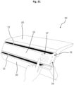
- a corresponding control panel with adjustment options in a polymer matrix is shown in the Figure 2B and 2C shown.
- a previously hidden control panel of the first and/or second control element 16, 17 can be activated and illuminated.
- the detection symbol can be deactivated and the operating display of the control elements 16, 17 illuminated when a hand approaches.
- a respective value can be adjusted by touching the decorative surface of the decorative element in the operating area of the control elements 16, 17 (see. Figure 2C ).
- a changed setting is implemented by means of the control unit 3 via servomotors on the air vent, which are coupled, for example, to a folding mechanism of air control flaps.
- the respective light-emitting operating display When the hand is removed from the decorative element 13 or the control panel of the control elements 16, 17, the respective light-emitting operating display remains active for a defined time and is only deactivated and no longer illuminated after a time threshold of 3 seconds or 5 seconds, for example, in which no further contact is detected or no approaching hand is detected. After such a predetermined period of time has elapsed, the respective operating display of the control elements 16, 17 is switched back to its idle state, in which again according to Figure 2A the position element 19 with its location symbol lights up. The set values for the air flow are retained.
- the position element 19 thus serves as an optical button that is visible in a resting state when the control elements 16, 17 are not operated. By tapping on the position element 19, the control elements 16, 17 or their respective operating displays can be activated and illuminated, while the position element 19 and the light-emitting location symbol are deactivated.
- Figure 3 shows a further embodiment of the air outlet device 10 using the multifunction display 5 of the motor vehicle 1.
- the control unit 3 is coupled in terms of signal technology to the first and second regulating elements 16, 17 and to the multifunction display 5, so that the first and/or second regulating elements 16, 17 can be controlled by means of the multifunction display 5 and the air flow can thus be electrically adjusted.
- a multifunction display is designed, for example, as an LCD display in the dashboard area of the motor vehicle 1 and is as an additional operating display in the display operating concept of the air outlet device 10.
- the multifunctional display 5 can be activated accordingly, as previously described, by tapping the location symbol of the position element 19.
- Figures 4 and 5 each illustrate a further embodiment of the air outlet device 10, which enables mechanical adjustment of the air flow through the ventilation gaps 11, 12.
- Such a mechanical control can be provided in addition to the electrical control described above.
- the first regulating element 16 comprises, for example, a rotatable annular element 162 and the second regulating element 17 a rotatable spherical element 172 for mechanically adjusting the air flow, which are each integrated in the decorative element 13 so that the annular element 162 surrounds the spherical element 172 (see. Figure 4 ).
- the first regulating element 16 may comprise a displaceable locking element 163 and the second regulating element 17 may comprise a displaceable sliding element 173 for mechanically adjusting the air flow, which are arranged in the lower, second ventilation gap 12, so that the locking element 163 and the sliding element 173 are arranged next to each other (see. Figure 5 ).
- the air outlet device can be adjusted mechanically and the air flow entering the interior can be adjusted with regard to its intensity, direction and focusing.
- Such adjustment is carried out by means of mechanical deflection on air control flaps and/or air control slats.
- the described air outlet device 10 enables a design-compatible integration of both an air outlet, in particular a register outlet, and an associated display control element, which is preferably arranged hidden in or on the decorative element 13.
- the air outlet is electrified and the display control element enables electronic adjustment of the air flow, in which one or more control panels are clearly visible in an operating state, while in a resting state they are minimally visible by a location symbol of the position element 19 or their position in the decorative element 13 is indicated by the location symbol.
Landscapes
- Engineering & Computer Science (AREA)
- Mechanical Engineering (AREA)
- Physics & Mathematics (AREA)
- Thermal Sciences (AREA)
- Chemical & Material Sciences (AREA)
- Combustion & Propulsion (AREA)
- Transportation (AREA)
- Air-Conditioning For Vehicles (AREA)
Claims (12)
- Véhicule automobile (1) avec un panneau (20) de planche de bord et un dispositif (10) de sortie d'air pour un habitacle du véhicule automobile (1), comprenant :- une première fente de ventilation (11) et une deuxième fente de ventilation (12), qui sont agencées à distance l'une de l'autre,- un élément décoratif (13) qui est relié au panneau (20) de planche de bord du véhicule automobile (1) et qui est agencé entre la première et la deuxième fentes de ventilation (11, 12) de manière à délimiter une face inférieure de la première fente de ventilation (11) et une face supérieure de la deuxième fente de ventilation (12), la première fente de ventilation (11) réalisant un accès de ventilation supérieur et la deuxième fente de ventilation (12) réalisant un accès de ventilation inférieur à l'intérieur du véhicule automobile (1) par rapport à une verticale du véhicule automobile (1) prêt à fonctionner, et l'élément décoratif (13) étant tourné vers l'intérieur du véhicule automobile (1) et réalisant un cache pour recouvrir une partie du dispositif (10) de sortie d'air, et- une unité de commande (15) qui est reliée à l'élément décoratif (13) et qui présente un premier élément de réglage (16) et un deuxième élément de réglage (17), une intensité d'un flux d'air à travers au moins une des fentes de ventilation (11, 12), au moyen du premier élément de réglage (16), et une orientation du flux d'air à travers au moins une des fentes de ventilation (11, 12) au moyen du deuxième élément de réglage (17), étant aptes à être réglées indépendamment l'une de l'autre, et- une unité de commande (3) qui est reliée au premier et au deuxième éléments de réglage (16, 17) par une technique de signal, caractériséen ce que le premier et le deuxième éléments de réglage (16, 17) présentent chacun un élément de surface tactile (161, 171), qui est intégré dans l'élément décoratif (13), de sorte qu'une position d'un objet sur l'un des éléments de surface tactiles (161, 171) du premier et/ou du deuxième éléments de réglage (16, 17) est apte à être déterminée au moyen de l'unité de commande (3) et que le flux d'air est apte à ainsi être commandé électriquement au moyen des éléments de réglage (16, 17).
- Véhicule automobile (1) selon la revendication 1, dans lequel le premier et le deuxième éléments de réglage (16, 17) présentent chacun un affichage de commande capacitif avec un moyen lumineux, qui est intégré dans l'élément décoratif (13) et au moyen duquel le flux d'air est apte à être commandé électriquement.
- Véhicule automobile (1) selon la revendication 2, dans lequel l'unité de commande (3) est agencée pour activer le moyen lumineux respectif de l'indicateur de commande respectif dans un état de fonctionnement dans lequel un objet est détecté sur l'un des éléments tactiles de surface (161, 171) du premier ou du deuxième élément de réglage (16, 17).
- Véhicule automobile (1) selon l'une des revendications 1 à 3, comprenant :
un élément de positionnement (19) adapté pour indiquer une position du premier et/ou du deuxième élément de réglage (16, 17) par rapport à l'élément décoratif (13). - Véhicule automobile (1) selon la revendication 4, dans lequel l'élément de position (19) comprend un moyen lumineux et est relié à l'unité de commande (3) par une technique de signal, et dans lequel l'unité de commande (3) est agencée pour activer le moyen lumineux de l'élément de position (19) dans un état de repos, dans lequel aucun objet n'est posé sur l'un des éléments de surface tactiles (161, 171) du premier ou du deuxième élément de réglage (16, 17) est détecté, et pour le désactiver dans un état de fonctionnement dans lequel un objet est détecté sur l'un des éléments de surface tactiles (161, 171) du premier ou du deuxième éléments de réglage (16, 17).
- Véhicule automobile (1) selon l'une des revendications 1 à 5, comprenant :
un système de détection de proximité qui est relié à l'unité de commande (3) par une technique de signal et au moyen duquel il est possible de déterminer une proximité d'un objet avec le premier ou le deuxième élément de réglage (16, 17), de sorte que le dispositif (10) de sortie d'air est apte à être actionné en fonction de signaux de mesure provenant du système de détection de proximité. - Véhicule automobile (1) selon la revendication 6, dans lequel le système de détection de proximité comprend un capteur capacitif, une DEL infrarouge ou une caméra gestuelle, au moyen desquels il est possible de déterminer respectivement une approche d'un objet vers le premier ou le deuxième élément de réglage (16, 17).
- Véhicule automobile (1) selon l'une des revendications 1 à 7, comprenant :
un capteur de reconnaissance d'objet, qui est relié à l'unité de commande (3) par une technique de signal et au moyen duquel une position d'un objet dans l'habitacle du véhicule automobile (1) est apte à être déterminée, de sorte que le dispositif (10) de sortie d'air est apte à être actionné en fonction de signaux de mesure provenant du capteur de reconnaissance d'objet. - Véhicule automobile (1) selon l'une des revendications 1 à 8, dans lequel l'unité de commande (3) est reliée par une technique de signal au premier et au deuxième éléments de réglage (16, 17) et à un affichage multifonctions (5) du véhicule automobile (1), de sorte que le premier et/ou le deuxième éléments de réglage (16, 17) sont aptes à être commandés au moyen de l'affichage multifonctions (5) et que le flux d'air est apte à ainsi être réglé électriquement au moyen des éléments de réglage (16, 17).
- Véhicule automobile (1) selon la revendication 1, dans lequel le premier élément de réglage (16) et le deuxième élément de réglage (17) présentent en outre chacun un liaison mécanique avec des volets de commande d'air respectifs, de sorte que le flux d'air est apte à être réglé mécaniquement au moyen des éléments de réglage (16, 17) .
- Véhicule automobile (1) selon la revendication 10, dans lequel le premier élément de réglage (16) comprend un élément annulaire rotatif (162) et le deuxième élément de réglage (17) comprend un élément sphérique rotatif (172) pour le réglage mécanique du flux d'air, qui sont respectivement intégrés dans l'élément de décoration (13) de sorte que l'élément annulaire (162) entoure l'élément sphérique (172).
- Véhicule automobile (1) selon la revendication 10, dans lequel le premier élément de réglage (16) comprend un élément de verrouillage coulissant (163) et le deuxième élément de réglage (17) comprend un élément coulissant qui coulisse (173) pour le réglage mécanique du flux d'air, agencés dans la première ou la deuxième fente de ventilation (11, 12), de sorte que l'élément de verrouillage (163) et l'élément coulissant (173) sont agencés l'un au-dessus de l'autre ou côte à côte.
Applications Claiming Priority (2)
| Application Number | Priority Date | Filing Date | Title |
|---|---|---|---|
| DE102017215809.3A DE102017215809B4 (de) | 2017-09-07 | 2017-09-07 | Luftauslassvorrichtung für einen Innenraum eines Kraftfahrzeugs und System |
| PCT/EP2018/063752 WO2019048089A1 (fr) | 2017-09-07 | 2018-05-25 | Dispositif de sortie d'air pour un habitacle d'un véhicule à moteur et système |
Publications (2)
| Publication Number | Publication Date |
|---|---|
| EP3678878A1 EP3678878A1 (fr) | 2020-07-15 |
| EP3678878B1 true EP3678878B1 (fr) | 2024-06-26 |
Family
ID=62563107
Family Applications (1)
| Application Number | Title | Priority Date | Filing Date |
|---|---|---|---|
| EP18729891.4A Active EP3678878B1 (fr) | 2017-09-07 | 2018-05-25 | Véhicule à moteur avec un dispositif de sortie d'air pour un intérieur du véhicule à moteur |
Country Status (5)
| Country | Link |
|---|---|
| US (1) | US11518215B2 (fr) |
| EP (1) | EP3678878B1 (fr) |
| CN (1) | CN111032387B (fr) |
| DE (1) | DE102017215809B4 (fr) |
| WO (1) | WO2019048089A1 (fr) |
Families Citing this family (12)
| Publication number | Priority date | Publication date | Assignee | Title |
|---|---|---|---|---|
| DE102018004870B4 (de) | 2018-06-19 | 2023-10-05 | Mercedes-Benz Group AG | Belüftungsvorrichtung für einen Kraftwagen, insbesondere für einen Personenkraftwagen |
| DE102019204046B4 (de) * | 2019-03-25 | 2021-07-15 | Volkswagen Aktiengesellschaft | Vorrichtung und Verfahren zur Ausgabe eines Parameterwerts in einem Fahrzeug |
| KR20200117483A (ko) * | 2019-04-04 | 2020-10-14 | 현대자동차주식회사 | 에어벤트 장치 |
| DE102019211575A1 (de) * | 2019-08-01 | 2021-02-04 | Brose Fahrzeugteile SE & Co. Kommanditgesellschaft, Coburg | Belüftungsvorrichtung für ein Fahrzeug und Verfahren zur Belüftung |
| DE102019218405A1 (de) * | 2019-11-27 | 2021-05-27 | Faurecia Innenraum Systeme Gmbh | Luftstromregeleinheit und ein verfahren zum regeln eines luftstroms |
| DE102019133471B4 (de) * | 2019-12-09 | 2021-09-02 | Dr. Ing. H.C. F. Porsche Aktiengesellschaft | Instrumententafel für einen Fahrzeuginnenraum eines Kraftfahrzeugs |
| KR102893967B1 (ko) * | 2020-10-30 | 2025-12-02 | 현대모비스 주식회사 | 차량의 에어벤트 장치 |
| CN112562413A (zh) * | 2020-12-09 | 2021-03-26 | 恒大新能源汽车投资控股集团有限公司 | 车辆碰撞预警方法、系统及车辆 |
| DE102022202705A1 (de) | 2022-03-18 | 2023-09-21 | Volkswagen Aktiengesellschaft | Lüftungsausströmer, Lüftungssystem und Kraftfahrzeug |
| US20240066950A1 (en) * | 2022-08-23 | 2024-02-29 | Aptera Motors Corp. | Multidirectional vent for vehicle hvac system |
| KR102827590B1 (ko) * | 2023-05-30 | 2025-07-02 | 현대모비스 주식회사 | 차량용 에어 벤트 시스템 |
| CN118810363B (zh) * | 2024-09-14 | 2024-12-27 | 宁波均胜群英汽车系统股份有限公司 | 一种双通道出风口 |
Family Cites Families (15)
| Publication number | Priority date | Publication date | Assignee | Title |
|---|---|---|---|---|
| DE29915938U1 (de) * | 1999-09-10 | 1999-11-04 | Utescheny-Endos GmbH, 75059 Zaisenhausen | Luftleitvorrichtung |
| DE10258955A1 (de) * | 2002-12-16 | 2004-07-01 | Bayerische Motoren Werke Ag | Bedieneinrichtung für eine Fahrzeugklimaanlage |
| DE102009001412B4 (de) * | 2009-03-09 | 2018-10-11 | Volkswagen Ag | Kapazitives Anzeige- und Bedienelement |
| US8775958B2 (en) * | 2010-04-14 | 2014-07-08 | Microsoft Corporation | Assigning Z-order to user interface elements |
| DE102011000924A1 (de) | 2011-02-24 | 2012-08-30 | Volkswagen Ag | Anordnung einer Anzeige-Eingabeeinheit in einem Fahrzeug |
| CN103702856B (zh) * | 2011-08-01 | 2017-04-26 | 丰田自动车株式会社 | 仪表板结构 |
| DE102013019197A1 (de) * | 2013-11-15 | 2015-05-21 | Audi Ag | Kraftfahrzeug-Klimatisierung mit adaptivem Luftausströmer |
| DE102014203511B3 (de) | 2014-02-26 | 2015-04-02 | Faurecia Innenraum Systeme Gmbh | Luftausströmer für ein Fahrzeug |
| DE202014007673U1 (de) | 2014-09-20 | 2016-01-14 | GM Global Technology Operations LLC (n. d. Ges. d. Staates Delaware) | Vorrichtung zur Anordnung an einer Instrumententafel eines Kraftfahrzeugs |
| US20160137028A1 (en) | 2014-11-19 | 2016-05-19 | Ford Global Technologies, Llc | Intelligent climate control system for a motor vehicle |
| JP6443188B2 (ja) | 2015-04-02 | 2018-12-26 | 株式会社デンソー | 車両空調用表示装置 |
| DE102015004846B3 (de) * | 2015-04-16 | 2016-03-10 | Audi Ag | Kraftfahrzeug umfassend eine Belüftungseinrichtung zum Zuführen von Luft in das Innere des Fahrzeugs, sowie Luftaustrittsdüse für ein Kraftfahrzeug |
| DE102015005126B3 (de) * | 2015-04-22 | 2016-06-02 | Audi Ag | Verfahren und Bedienungsvorrichtung zum Bedienen einer Klimaanlage eines Fahrzeugs |
| DE102015222039B4 (de) * | 2015-11-10 | 2020-11-19 | Volkswagen Aktiengesellschaft | Verfahren und System zum Betreiben einer Belüftungseinrichtung in einem Fahrzeug |
| US11034214B2 (en) * | 2017-10-04 | 2021-06-15 | Ford Global Technologies, Llc | Integrated display and ventilation assembly |
-
2017
- 2017-09-07 DE DE102017215809.3A patent/DE102017215809B4/de active Active
-
2018
- 2018-05-25 CN CN201880051074.4A patent/CN111032387B/zh active Active
- 2018-05-25 WO PCT/EP2018/063752 patent/WO2019048089A1/fr not_active Ceased
- 2018-05-25 EP EP18729891.4A patent/EP3678878B1/fr active Active
-
2020
- 2020-03-06 US US16/811,692 patent/US11518215B2/en active Active
Also Published As
| Publication number | Publication date |
|---|---|
| WO2019048089A1 (fr) | 2019-03-14 |
| DE102017215809B4 (de) | 2022-06-30 |
| CN111032387B (zh) | 2023-08-01 |
| US20200207181A1 (en) | 2020-07-02 |
| EP3678878A1 (fr) | 2020-07-15 |
| US11518215B2 (en) | 2022-12-06 |
| DE102017215809A1 (de) | 2019-03-07 |
| CN111032387A (zh) | 2020-04-17 |
Similar Documents
| Publication | Publication Date | Title |
|---|---|---|
| EP3678878B1 (fr) | Véhicule à moteur avec un dispositif de sortie d'air pour un intérieur du véhicule à moteur | |
| DE102014019125B4 (de) | Kraftfahrzeug mit einer Steuereinrichtung und Verfahren zur Steuerung einer Einrichtung abhängig von einer Sitzneigung | |
| EP2885142B1 (fr) | Dispositif de réglage d'un système de climatisation d'un véhicule et procédé correspondant | |
| DE102012021519B4 (de) | Lüftungssystem für ein Kraftfahrzeug sowie Verfahren zum Betreiben eines solchen | |
| DE102010018105B4 (de) | Fahrzeugcockpit mit einer Bedieneinrichtung zum Erfassen von Nutzereingaben und Verfahren zum Betreiben einer solchen | |
| WO2017108552A1 (fr) | Véhicule automobile comprenant un module de tableau de bord | |
| DE102009011710A1 (de) | Anordnung zur Luftverteilung im Innenraum eines Kraftfahrzeuges | |
| DE102016220671B4 (de) | Luftausströmer für Heizungs- und Belüftungs- oder Klimaanlagen von Kraftfahrzeugen | |
| EP3553374B1 (fr) | Dispositif d'éclairage à base de semi-conducteur | |
| EP3068645B1 (fr) | Climatisation de véhicule automobile avec aérateur adaptatif | |
| DE102012108962B4 (de) | Passagier-Versorgungseinheit für Land-, Luft- und Wasserfahrzeuge | |
| DE602006000824T2 (de) | Luftverteilsystem mit berührungsloser Betätigung der Düsen | |
| DE102018111344B4 (de) | Multifunktionseinrichtung sowie Armaturenbrett mit einer solchen | |
| DE102019203664B4 (de) | Kraftfahrzeug | |
| DE102015011891A1 (de) | Verfahren und Vorrichtung zur Einstellung eines Leselichtes und einer Innenraumbeleuchtung in einem Fahrzeug | |
| DE102018106156A1 (de) | Belüftungsvorrichtung für einen Innenbereich eines Kraftfahrzeugs, insbesondere in einem Bereich einer zweiten Sitzreihe | |
| EP3088220B1 (fr) | Procede et dispositif de commande destines a regler un dispositif de climatisation d'un vehicule automobile | |
| DE102016200110B4 (de) | Armaturentafel, Fortbewegungsmittel und Vorrichtung zur Bedienung eines Heiz-Klima-Systems eines Fortbewegungsmittels | |
| DE102012018290B4 (de) | Bedienvorrichtung für einen Kraftwagen und Verfahren zum Betreiben einer Bedienvorrichtung für einen Kraftwagen | |
| DE102014015403A1 (de) | Bedienvorrichtung zum Steuern von wenigstens einer Funktion von wenigstens einer kraftfahrzeugseitigen Einrichtung | |
| DE102016221075A1 (de) | Ausströmer für eine Fahrzeugklimaanlage, Fahrzeug mit einer Fahrzeugklimaanlage, Verfahren, Vorrichtung und computerlesbares Speichermedium mit Instruktionen zum Anzeigen von Einstellgrössen einer Fahrzeugklimaanlage | |
| DE102014011119B4 (de) | Kraftfahrzeug mit Bildschirm und Gebläseauslass | |
| DE102019129797A1 (de) | Dachbedienvorrichtung, Dachbediensystem, Verwendung einer Dachbedienvorrichtung und Fahrzeug mit einer Dachbedienvorrichtung | |
| DE102009006927B4 (de) | Vorrichtung und Verfahren zur Steuerung der Beleuchtung von Anzeige- und/oder Bedienelementen | |
| EP4043263B1 (fr) | Procédé de commande ds fonctions de véhicule |
Legal Events
| Date | Code | Title | Description |
|---|---|---|---|
| STAA | Information on the status of an ep patent application or granted ep patent |
Free format text: STATUS: UNKNOWN |
|
| STAA | Information on the status of an ep patent application or granted ep patent |
Free format text: STATUS: THE INTERNATIONAL PUBLICATION HAS BEEN MADE |
|
| PUAI | Public reference made under article 153(3) epc to a published international application that has entered the european phase |
Free format text: ORIGINAL CODE: 0009012 |
|
| STAA | Information on the status of an ep patent application or granted ep patent |
Free format text: STATUS: REQUEST FOR EXAMINATION WAS MADE |
|
| 17P | Request for examination filed |
Effective date: 20200323 |
|
| AK | Designated contracting states |
Kind code of ref document: A1 Designated state(s): AL AT BE BG CH CY CZ DE DK EE ES FI FR GB GR HR HU IE IS IT LI LT LU LV MC MK MT NL NO PL PT RO RS SE SI SK SM TR |
|
| AX | Request for extension of the european patent |
Extension state: BA ME |
|
| DAV | Request for validation of the european patent (deleted) | ||
| DAX | Request for extension of the european patent (deleted) | ||
| STAA | Information on the status of an ep patent application or granted ep patent |
Free format text: STATUS: EXAMINATION IS IN PROGRESS |
|
| 17Q | First examination report despatched |
Effective date: 20210129 |
|
| P01 | Opt-out of the competence of the unified patent court (upc) registered |
Effective date: 20230503 |
|
| RBV | Designated contracting states (corrected) |
Designated state(s): AL AT BE BG CH CY CZ DK EE ES FI FR GB GR HR HU IE IS IT LI LT LU LV MC MK MT NL NO PL PT RO RS SE SI SK SM TR |
|
| REG | Reference to a national code |
Ref country code: DE Ref legal event code: R108 |
|
| GRAP | Despatch of communication of intention to grant a patent |
Free format text: ORIGINAL CODE: EPIDOSNIGR1 |
|
| STAA | Information on the status of an ep patent application or granted ep patent |
Free format text: STATUS: GRANT OF PATENT IS INTENDED |
|
| INTG | Intention to grant announced |
Effective date: 20240207 |
|
| GRAS | Grant fee paid |
Free format text: ORIGINAL CODE: EPIDOSNIGR3 |
|
| GRAA | (expected) grant |
Free format text: ORIGINAL CODE: 0009210 |
|
| STAA | Information on the status of an ep patent application or granted ep patent |
Free format text: STATUS: THE PATENT HAS BEEN GRANTED |
|
| AK | Designated contracting states |
Kind code of ref document: B1 Designated state(s): AL AT BE BG CH CY CZ DK EE ES FI FR GB GR HR HU IE IS IT LI LT LU LV MC MK MT NL NO PL PT RO RS SE SI SK SM TR |
|
| REG | Reference to a national code |
Ref country code: GB Ref legal event code: FG4D Free format text: NOT ENGLISH |
|
| REG | Reference to a national code |
Ref country code: CH Ref legal event code: EP |
|
| PG25 | Lapsed in a contracting state [announced via postgrant information from national office to epo] |
Ref country code: BG Free format text: LAPSE BECAUSE OF FAILURE TO SUBMIT A TRANSLATION OF THE DESCRIPTION OR TO PAY THE FEE WITHIN THE PRESCRIBED TIME-LIMIT Effective date: 20240626 |
|
| PG25 | Lapsed in a contracting state [announced via postgrant information from national office to epo] |
Ref country code: FI Free format text: LAPSE BECAUSE OF FAILURE TO SUBMIT A TRANSLATION OF THE DESCRIPTION OR TO PAY THE FEE WITHIN THE PRESCRIBED TIME-LIMIT Effective date: 20240626 Ref country code: HR Free format text: LAPSE BECAUSE OF FAILURE TO SUBMIT A TRANSLATION OF THE DESCRIPTION OR TO PAY THE FEE WITHIN THE PRESCRIBED TIME-LIMIT Effective date: 20240626 |
|
| REG | Reference to a national code |
Ref country code: LT Ref legal event code: MG9D |
|
| PG25 | Lapsed in a contracting state [announced via postgrant information from national office to epo] |
Ref country code: GR Free format text: LAPSE BECAUSE OF FAILURE TO SUBMIT A TRANSLATION OF THE DESCRIPTION OR TO PAY THE FEE WITHIN THE PRESCRIBED TIME-LIMIT Effective date: 20240927 |
|
| PG25 | Lapsed in a contracting state [announced via postgrant information from national office to epo] |
Ref country code: LV Free format text: LAPSE BECAUSE OF FAILURE TO SUBMIT A TRANSLATION OF THE DESCRIPTION OR TO PAY THE FEE WITHIN THE PRESCRIBED TIME-LIMIT Effective date: 20240626 |
|
| REG | Reference to a national code |
Ref country code: NL Ref legal event code: MP Effective date: 20240626 |
|
| PG25 | Lapsed in a contracting state [announced via postgrant information from national office to epo] |
Ref country code: NO Free format text: LAPSE BECAUSE OF FAILURE TO SUBMIT A TRANSLATION OF THE DESCRIPTION OR TO PAY THE FEE WITHIN THE PRESCRIBED TIME-LIMIT Effective date: 20240926 Ref country code: LV Free format text: LAPSE BECAUSE OF FAILURE TO SUBMIT A TRANSLATION OF THE DESCRIPTION OR TO PAY THE FEE WITHIN THE PRESCRIBED TIME-LIMIT Effective date: 20240626 Ref country code: HR Free format text: LAPSE BECAUSE OF FAILURE TO SUBMIT A TRANSLATION OF THE DESCRIPTION OR TO PAY THE FEE WITHIN THE PRESCRIBED TIME-LIMIT Effective date: 20240626 Ref country code: GR Free format text: LAPSE BECAUSE OF FAILURE TO SUBMIT A TRANSLATION OF THE DESCRIPTION OR TO PAY THE FEE WITHIN THE PRESCRIBED TIME-LIMIT Effective date: 20240927 Ref country code: FI Free format text: LAPSE BECAUSE OF FAILURE TO SUBMIT A TRANSLATION OF THE DESCRIPTION OR TO PAY THE FEE WITHIN THE PRESCRIBED TIME-LIMIT Effective date: 20240626 Ref country code: BG Free format text: LAPSE BECAUSE OF FAILURE TO SUBMIT A TRANSLATION OF THE DESCRIPTION OR TO PAY THE FEE WITHIN THE PRESCRIBED TIME-LIMIT Effective date: 20240626 Ref country code: RS Free format text: LAPSE BECAUSE OF FAILURE TO SUBMIT A TRANSLATION OF THE DESCRIPTION OR TO PAY THE FEE WITHIN THE PRESCRIBED TIME-LIMIT Effective date: 20240926 |
|
| PG25 | Lapsed in a contracting state [announced via postgrant information from national office to epo] |
Ref country code: NL Free format text: LAPSE BECAUSE OF FAILURE TO SUBMIT A TRANSLATION OF THE DESCRIPTION OR TO PAY THE FEE WITHIN THE PRESCRIBED TIME-LIMIT Effective date: 20240626 |
|
| PG25 | Lapsed in a contracting state [announced via postgrant information from national office to epo] |
Ref country code: NL Free format text: LAPSE BECAUSE OF FAILURE TO SUBMIT A TRANSLATION OF THE DESCRIPTION OR TO PAY THE FEE WITHIN THE PRESCRIBED TIME-LIMIT Effective date: 20240626 |
|
| PG25 | Lapsed in a contracting state [announced via postgrant information from national office to epo] |
Ref country code: PT Free format text: LAPSE BECAUSE OF FAILURE TO SUBMIT A TRANSLATION OF THE DESCRIPTION OR TO PAY THE FEE WITHIN THE PRESCRIBED TIME-LIMIT Effective date: 20241028 |
|
| PG25 | Lapsed in a contracting state [announced via postgrant information from national office to epo] |
Ref country code: PT Free format text: LAPSE BECAUSE OF FAILURE TO SUBMIT A TRANSLATION OF THE DESCRIPTION OR TO PAY THE FEE WITHIN THE PRESCRIBED TIME-LIMIT Effective date: 20241028 |
|
| P02 | Opt-out of the competence of the unified patent court (upc) changed |
Free format text: CASE NUMBER: APP_65322/2024 Effective date: 20241211 |
|
| PG25 | Lapsed in a contracting state [announced via postgrant information from national office to epo] |
Ref country code: PL Free format text: LAPSE BECAUSE OF FAILURE TO SUBMIT A TRANSLATION OF THE DESCRIPTION OR TO PAY THE FEE WITHIN THE PRESCRIBED TIME-LIMIT Effective date: 20240626 |
|
| PG25 | Lapsed in a contracting state [announced via postgrant information from national office to epo] |
Ref country code: EE Free format text: LAPSE BECAUSE OF FAILURE TO SUBMIT A TRANSLATION OF THE DESCRIPTION OR TO PAY THE FEE WITHIN THE PRESCRIBED TIME-LIMIT Effective date: 20240626 |
|
| PG25 | Lapsed in a contracting state [announced via postgrant information from national office to epo] |
Ref country code: IS Free format text: LAPSE BECAUSE OF FAILURE TO SUBMIT A TRANSLATION OF THE DESCRIPTION OR TO PAY THE FEE WITHIN THE PRESCRIBED TIME-LIMIT Effective date: 20241026 |
|
| PG25 | Lapsed in a contracting state [announced via postgrant information from national office to epo] |
Ref country code: CZ Free format text: LAPSE BECAUSE OF FAILURE TO SUBMIT A TRANSLATION OF THE DESCRIPTION OR TO PAY THE FEE WITHIN THE PRESCRIBED TIME-LIMIT Effective date: 20240626 |
|
| PG25 | Lapsed in a contracting state [announced via postgrant information from national office to epo] |
Ref country code: RO Free format text: LAPSE BECAUSE OF FAILURE TO SUBMIT A TRANSLATION OF THE DESCRIPTION OR TO PAY THE FEE WITHIN THE PRESCRIBED TIME-LIMIT Effective date: 20240626 Ref country code: SK Free format text: LAPSE BECAUSE OF FAILURE TO SUBMIT A TRANSLATION OF THE DESCRIPTION OR TO PAY THE FEE WITHIN THE PRESCRIBED TIME-LIMIT Effective date: 20240626 |
|
| PG25 | Lapsed in a contracting state [announced via postgrant information from national office to epo] |
Ref country code: ES Free format text: LAPSE BECAUSE OF FAILURE TO SUBMIT A TRANSLATION OF THE DESCRIPTION OR TO PAY THE FEE WITHIN THE PRESCRIBED TIME-LIMIT Effective date: 20240626 Ref country code: SM Free format text: LAPSE BECAUSE OF FAILURE TO SUBMIT A TRANSLATION OF THE DESCRIPTION OR TO PAY THE FEE WITHIN THE PRESCRIBED TIME-LIMIT Effective date: 20240626 |
|
| PG25 | Lapsed in a contracting state [announced via postgrant information from national office to epo] |
Ref country code: SM Free format text: LAPSE BECAUSE OF FAILURE TO SUBMIT A TRANSLATION OF THE DESCRIPTION OR TO PAY THE FEE WITHIN THE PRESCRIBED TIME-LIMIT Effective date: 20240626 Ref country code: SK Free format text: LAPSE BECAUSE OF FAILURE TO SUBMIT A TRANSLATION OF THE DESCRIPTION OR TO PAY THE FEE WITHIN THE PRESCRIBED TIME-LIMIT Effective date: 20240626 Ref country code: RO Free format text: LAPSE BECAUSE OF FAILURE TO SUBMIT A TRANSLATION OF THE DESCRIPTION OR TO PAY THE FEE WITHIN THE PRESCRIBED TIME-LIMIT Effective date: 20240626 Ref country code: PL Free format text: LAPSE BECAUSE OF FAILURE TO SUBMIT A TRANSLATION OF THE DESCRIPTION OR TO PAY THE FEE WITHIN THE PRESCRIBED TIME-LIMIT Effective date: 20240626 Ref country code: IS Free format text: LAPSE BECAUSE OF FAILURE TO SUBMIT A TRANSLATION OF THE DESCRIPTION OR TO PAY THE FEE WITHIN THE PRESCRIBED TIME-LIMIT Effective date: 20241026 Ref country code: ES Free format text: LAPSE BECAUSE OF FAILURE TO SUBMIT A TRANSLATION OF THE DESCRIPTION OR TO PAY THE FEE WITHIN THE PRESCRIBED TIME-LIMIT Effective date: 20240626 Ref country code: EE Free format text: LAPSE BECAUSE OF FAILURE TO SUBMIT A TRANSLATION OF THE DESCRIPTION OR TO PAY THE FEE WITHIN THE PRESCRIBED TIME-LIMIT Effective date: 20240626 Ref country code: CZ Free format text: LAPSE BECAUSE OF FAILURE TO SUBMIT A TRANSLATION OF THE DESCRIPTION OR TO PAY THE FEE WITHIN THE PRESCRIBED TIME-LIMIT Effective date: 20240626 |
|
| PG25 | Lapsed in a contracting state [announced via postgrant information from national office to epo] |
Ref country code: DK Free format text: LAPSE BECAUSE OF FAILURE TO SUBMIT A TRANSLATION OF THE DESCRIPTION OR TO PAY THE FEE WITHIN THE PRESCRIBED TIME-LIMIT Effective date: 20240626 |
|
| PLBE | No opposition filed within time limit |
Free format text: ORIGINAL CODE: 0009261 |
|
| STAA | Information on the status of an ep patent application or granted ep patent |
Free format text: STATUS: NO OPPOSITION FILED WITHIN TIME LIMIT |
|
| 26N | No opposition filed |
Effective date: 20250327 |
|
| PGFP | Annual fee paid to national office [announced via postgrant information from national office to epo] |
Ref country code: GB Payment date: 20250522 Year of fee payment: 8 |
|
| PGFP | Annual fee paid to national office [announced via postgrant information from national office to epo] |
Ref country code: IT Payment date: 20250530 Year of fee payment: 8 |
|
| PGFP | Annual fee paid to national office [announced via postgrant information from national office to epo] |
Ref country code: FR Payment date: 20250521 Year of fee payment: 8 |
|
| PG25 | Lapsed in a contracting state [announced via postgrant information from national office to epo] |
Ref country code: SE Free format text: LAPSE BECAUSE OF FAILURE TO SUBMIT A TRANSLATION OF THE DESCRIPTION OR TO PAY THE FEE WITHIN THE PRESCRIBED TIME-LIMIT Effective date: 20240626 |
|
| REG | Reference to a national code |
Ref country code: CH Ref legal event code: H13 Free format text: ST27 STATUS EVENT CODE: U-0-0-H10-H13 (AS PROVIDED BY THE NATIONAL OFFICE) Effective date: 20251223 |
|
| PG25 | Lapsed in a contracting state [announced via postgrant information from national office to epo] |
Ref country code: LU Free format text: LAPSE BECAUSE OF NON-PAYMENT OF DUE FEES Effective date: 20250525 |
|
| PG25 | Lapsed in a contracting state [announced via postgrant information from national office to epo] |
Ref country code: CH Free format text: LAPSE BECAUSE OF NON-PAYMENT OF DUE FEES Effective date: 20250531 |
|
| REG | Reference to a national code |
Ref country code: BE Ref legal event code: MM Effective date: 20250531 |
|
| PG25 | Lapsed in a contracting state [announced via postgrant information from national office to epo] |
Ref country code: MC Free format text: LAPSE BECAUSE OF FAILURE TO SUBMIT A TRANSLATION OF THE DESCRIPTION OR TO PAY THE FEE WITHIN THE PRESCRIBED TIME-LIMIT Effective date: 20240626 |
|
| PG25 | Lapsed in a contracting state [announced via postgrant information from national office to epo] |
Ref country code: IE Free format text: LAPSE BECAUSE OF NON-PAYMENT OF DUE FEES Effective date: 20250525 |
|
| PG25 | Lapsed in a contracting state [announced via postgrant information from national office to epo] |
Ref country code: BE Free format text: LAPSE BECAUSE OF NON-PAYMENT OF DUE FEES Effective date: 20250531 |