EP3553450A1 - Unité d'échangeur de chaleur - Google Patents
Unité d'échangeur de chaleur Download PDFInfo
- Publication number
- EP3553450A1 EP3553450A1 EP19000173.5A EP19000173A EP3553450A1 EP 3553450 A1 EP3553450 A1 EP 3553450A1 EP 19000173 A EP19000173 A EP 19000173A EP 3553450 A1 EP3553450 A1 EP 3553450A1
- Authority
- EP
- European Patent Office
- Prior art keywords
- heat exchanger
- distributor
- holding frame
- exchanger unit
- thermoelectric
- Prior art date
- Legal status (The legal status is an assumption and is not a legal conclusion. Google has not performed a legal analysis and makes no representation as to the accuracy of the status listed.)
- Granted
Links
Images


Classifications
-
- F—MECHANICAL ENGINEERING; LIGHTING; HEATING; WEAPONS; BLASTING
- F28—HEAT EXCHANGE IN GENERAL
- F28F—DETAILS OF HEAT-EXCHANGE AND HEAT-TRANSFER APPARATUS, OF GENERAL APPLICATION
- F28F9/00—Casings; Header boxes; Auxiliary supports for elements; Auxiliary members within casings
- F28F9/001—Casings in the form of plate-like arrangements; Frames enclosing a heat exchange core
- F28F9/002—Casings in the form of plate-like arrangements; Frames enclosing a heat exchange core with fastening means for other structures
-
- B—PERFORMING OPERATIONS; TRANSPORTING
- B60—VEHICLES IN GENERAL
- B60N—SEATS SPECIALLY ADAPTED FOR VEHICLES; VEHICLE PASSENGER ACCOMMODATION NOT OTHERWISE PROVIDED FOR
- B60N3/00—Arrangements or adaptations of other passenger fittings, not otherwise provided for
- B60N3/10—Arrangements or adaptations of other passenger fittings, not otherwise provided for of receptacles for food or beverages, e.g. refrigerated
- B60N3/104—Arrangements or adaptations of other passenger fittings, not otherwise provided for of receptacles for food or beverages, e.g. refrigerated with refrigerating or warming systems
-
- F—MECHANICAL ENGINEERING; LIGHTING; HEATING; WEAPONS; BLASTING
- F25—REFRIGERATION OR COOLING; COMBINED HEATING AND REFRIGERATION SYSTEMS; HEAT PUMP SYSTEMS; MANUFACTURE OR STORAGE OF ICE; LIQUEFACTION SOLIDIFICATION OF GASES
- F25B—REFRIGERATION MACHINES, PLANTS OR SYSTEMS; COMBINED HEATING AND REFRIGERATION SYSTEMS; HEAT PUMP SYSTEMS
- F25B21/00—Machines, plants or systems, using electric or magnetic effects
- F25B21/02—Machines, plants or systems, using electric or magnetic effects using Peltier effect; using Nernst-Ettinghausen effect
-
- F—MECHANICAL ENGINEERING; LIGHTING; HEATING; WEAPONS; BLASTING
- F28—HEAT EXCHANGE IN GENERAL
- F28D—HEAT-EXCHANGE APPARATUS, NOT PROVIDED FOR IN ANOTHER SUBCLASS, IN WHICH THE HEAT-EXCHANGE MEDIA DO NOT COME INTO DIRECT CONTACT
- F28D1/00—Heat-exchange apparatus having stationary conduit assemblies for one heat-exchange medium only, the media being in contact with different sides of the conduit wall, in which the other heat-exchange medium is a large body of fluid, e.g. domestic or motor car radiators
- F28D1/02—Heat-exchange apparatus having stationary conduit assemblies for one heat-exchange medium only, the media being in contact with different sides of the conduit wall, in which the other heat-exchange medium is a large body of fluid, e.g. domestic or motor car radiators with heat-exchange conduits immersed in the body of fluid
- F28D1/04—Heat-exchange apparatus having stationary conduit assemblies for one heat-exchange medium only, the media being in contact with different sides of the conduit wall, in which the other heat-exchange medium is a large body of fluid, e.g. domestic or motor car radiators with heat-exchange conduits immersed in the body of fluid with tubular conduits
- F28D1/053—Heat-exchange apparatus having stationary conduit assemblies for one heat-exchange medium only, the media being in contact with different sides of the conduit wall, in which the other heat-exchange medium is a large body of fluid, e.g. domestic or motor car radiators with heat-exchange conduits immersed in the body of fluid with tubular conduits the conduits being straight
- F28D1/0535—Heat-exchange apparatus having stationary conduit assemblies for one heat-exchange medium only, the media being in contact with different sides of the conduit wall, in which the other heat-exchange medium is a large body of fluid, e.g. domestic or motor car radiators with heat-exchange conduits immersed in the body of fluid with tubular conduits the conduits being straight the conduits having a non-circular cross-section
- F28D1/05366—Assemblies of conduits connected to common headers, e.g. core type radiators
- F28D1/05383—Assemblies of conduits connected to common headers, e.g. core type radiators with multiple rows of conduits or with multi-channel conduits
-
- F—MECHANICAL ENGINEERING; LIGHTING; HEATING; WEAPONS; BLASTING
- F28—HEAT EXCHANGE IN GENERAL
- F28F—DETAILS OF HEAT-EXCHANGE AND HEAT-TRANSFER APPARATUS, OF GENERAL APPLICATION
- F28F1/00—Tubular elements; Assemblies of tubular elements
- F28F1/02—Tubular elements of cross-section which is non-circular
- F28F1/022—Tubular elements of cross-section which is non-circular with multiple channels
-
- F—MECHANICAL ENGINEERING; LIGHTING; HEATING; WEAPONS; BLASTING
- F28—HEAT EXCHANGE IN GENERAL
- F28F—DETAILS OF HEAT-EXCHANGE AND HEAT-TRANSFER APPARATUS, OF GENERAL APPLICATION
- F28F3/00—Plate-like or laminated elements; Assemblies of plate-like or laminated elements
- F28F3/12—Elements constructed in the shape of a hollow panel, e.g. with channels
-
- F—MECHANICAL ENGINEERING; LIGHTING; HEATING; WEAPONS; BLASTING
- F28—HEAT EXCHANGE IN GENERAL
- F28F—DETAILS OF HEAT-EXCHANGE AND HEAT-TRANSFER APPARATUS, OF GENERAL APPLICATION
- F28F9/00—Casings; Header boxes; Auxiliary supports for elements; Auxiliary members within casings
- F28F9/02—Header boxes; End plates
- F28F9/04—Arrangements for sealing elements into header boxes or end plates
- F28F9/06—Arrangements for sealing elements into header boxes or end plates by dismountable joints
-
- F—MECHANICAL ENGINEERING; LIGHTING; HEATING; WEAPONS; BLASTING
- F28—HEAT EXCHANGE IN GENERAL
- F28F—DETAILS OF HEAT-EXCHANGE AND HEAT-TRANSFER APPARATUS, OF GENERAL APPLICATION
- F28F9/00—Casings; Header boxes; Auxiliary supports for elements; Auxiliary members within casings
- F28F9/02—Header boxes; End plates
- F28F9/04—Arrangements for sealing elements into header boxes or end plates
- F28F9/16—Arrangements for sealing elements into header boxes or end plates by permanent joints, e.g. by rolling
- F28F9/165—Arrangements for sealing elements into header boxes or end plates by permanent joints, e.g. by rolling by using additional preformed parts, e.g. sleeves, gaskets
-
- H—ELECTRICITY
- H10—SEMICONDUCTOR DEVICES; ELECTRIC SOLID-STATE DEVICES NOT OTHERWISE PROVIDED FOR
- H10N—ELECTRIC SOLID-STATE DEVICES NOT OTHERWISE PROVIDED FOR
- H10N10/00—Thermoelectric devices comprising a junction of dissimilar materials, i.e. devices exhibiting Seebeck or Peltier effects
- H10N10/10—Thermoelectric devices comprising a junction of dissimilar materials, i.e. devices exhibiting Seebeck or Peltier effects operating with only the Peltier or Seebeck effects
- H10N10/13—Thermoelectric devices comprising a junction of dissimilar materials, i.e. devices exhibiting Seebeck or Peltier effects operating with only the Peltier or Seebeck effects characterised by the heat-exchanging means at the junction
-
- F—MECHANICAL ENGINEERING; LIGHTING; HEATING; WEAPONS; BLASTING
- F25—REFRIGERATION OR COOLING; COMBINED HEATING AND REFRIGERATION SYSTEMS; HEAT PUMP SYSTEMS; MANUFACTURE OR STORAGE OF ICE; LIQUEFACTION SOLIDIFICATION OF GASES
- F25B—REFRIGERATION MACHINES, PLANTS OR SYSTEMS; COMBINED HEATING AND REFRIGERATION SYSTEMS; HEAT PUMP SYSTEMS
- F25B2321/00—Details of machines, plants or systems, using electric or magnetic effects
- F25B2321/02—Details of machines, plants or systems, using electric or magnetic effects using Peltier effects; using Nernst-Ettinghausen effects
- F25B2321/025—Removal of heat
- F25B2321/0252—Removal of heat by liquids or two-phase fluids
-
- F—MECHANICAL ENGINEERING; LIGHTING; HEATING; WEAPONS; BLASTING
- F28—HEAT EXCHANGE IN GENERAL
- F28D—HEAT-EXCHANGE APPARATUS, NOT PROVIDED FOR IN ANOTHER SUBCLASS, IN WHICH THE HEAT-EXCHANGE MEDIA DO NOT COME INTO DIRECT CONTACT
- F28D21/00—Heat-exchange apparatus not covered by any of the groups F28D1/00 - F28D20/00
- F28D2021/0019—Other heat exchangers for particular applications; Heat exchange systems not otherwise provided for
- F28D2021/0028—Other heat exchangers for particular applications; Heat exchange systems not otherwise provided for for cooling heat generating elements, e.g. for cooling electronic components or electric devices
- F28D2021/0029—Heat sinks
-
- F—MECHANICAL ENGINEERING; LIGHTING; HEATING; WEAPONS; BLASTING
- F28—HEAT EXCHANGE IN GENERAL
- F28F—DETAILS OF HEAT-EXCHANGE AND HEAT-TRANSFER APPARATUS, OF GENERAL APPLICATION
- F28F21/00—Constructions of heat-exchange apparatus characterised by the selection of particular materials
- F28F21/06—Constructions of heat-exchange apparatus characterised by the selection of particular materials of plastics material
- F28F21/067—Details
-
- F—MECHANICAL ENGINEERING; LIGHTING; HEATING; WEAPONS; BLASTING
- F28—HEAT EXCHANGE IN GENERAL
- F28F—DETAILS OF HEAT-EXCHANGE AND HEAT-TRANSFER APPARATUS, OF GENERAL APPLICATION
- F28F21/00—Constructions of heat-exchange apparatus characterised by the selection of particular materials
- F28F21/08—Constructions of heat-exchange apparatus characterised by the selection of particular materials of metal
- F28F21/081—Heat exchange elements made from metals or metal alloys
- F28F21/084—Heat exchange elements made from metals or metal alloys from aluminium or aluminium alloys
-
- F—MECHANICAL ENGINEERING; LIGHTING; HEATING; WEAPONS; BLASTING
- F28—HEAT EXCHANGE IN GENERAL
- F28F—DETAILS OF HEAT-EXCHANGE AND HEAT-TRANSFER APPARATUS, OF GENERAL APPLICATION
- F28F2255/00—Heat exchanger elements made of materials having special features or resulting from particular manufacturing processes
- F28F2255/06—Heat exchanger elements made of materials having special features or resulting from particular manufacturing processes composite, e.g. polymers with fillers or fibres
-
- F—MECHANICAL ENGINEERING; LIGHTING; HEATING; WEAPONS; BLASTING
- F28—HEAT EXCHANGE IN GENERAL
- F28F—DETAILS OF HEAT-EXCHANGE AND HEAT-TRANSFER APPARATUS, OF GENERAL APPLICATION
- F28F2255/00—Heat exchanger elements made of materials having special features or resulting from particular manufacturing processes
- F28F2255/16—Heat exchanger elements made of materials having special features or resulting from particular manufacturing processes extruded
-
- F—MECHANICAL ENGINEERING; LIGHTING; HEATING; WEAPONS; BLASTING
- F28—HEAT EXCHANGE IN GENERAL
- F28F—DETAILS OF HEAT-EXCHANGE AND HEAT-TRANSFER APPARATUS, OF GENERAL APPLICATION
- F28F2275/00—Fastening; Joining
- F28F2275/08—Fastening; Joining by clamping or clipping
- F28F2275/085—Fastening; Joining by clamping or clipping with snap connection
-
- F—MECHANICAL ENGINEERING; LIGHTING; HEATING; WEAPONS; BLASTING
- F28—HEAT EXCHANGE IN GENERAL
- F28F—DETAILS OF HEAT-EXCHANGE AND HEAT-TRANSFER APPARATUS, OF GENERAL APPLICATION
- F28F2275/00—Fastening; Joining
- F28F2275/20—Fastening; Joining with threaded elements
-
- F—MECHANICAL ENGINEERING; LIGHTING; HEATING; WEAPONS; BLASTING
- F28—HEAT EXCHANGE IN GENERAL
- F28F—DETAILS OF HEAT-EXCHANGE AND HEAT-TRANSFER APPARATUS, OF GENERAL APPLICATION
- F28F9/00—Casings; Header boxes; Auxiliary supports for elements; Auxiliary members within casings
- F28F9/02—Header boxes; End plates
- F28F9/0246—Arrangements for connecting header boxes with flow lines
Definitions
- the invention relates to a heat exchanger unit comprising at least one thermoelectric element, in particular a Peltier element, at least one heat exchanger element for heat exchange with the thermoelectric element and at least one distributor element for supplying and discharging a heat exchanger medium flowing through the at least one heat exchanger element.
- thermoelectric elements to use the thermoelectric effect.
- thermoelectric elements are known in the form of Peltier elements. When electrically applied to such thermoelectric elements, such as Peltier elements, these form a hot side and a cold side, which also changes with a change of polarity. In order to allow cooling, heat is dissipated from the hot side in order to create a temperature difference to the cold side and thereby to be able to provide a lower temperature level with respect to the ambient temperature of the thermoelectric element.
- thermoelectric elements can be used in particular for controlling the temperature of energy storage or for temperature control functions of vehicle components, such as an air conditioner, a cup holder, a cooler, a refrigerator, a seat heater, a vehicle interior cooling or decentralized cooling elements. If, for example, by means of such a Peltier element cooling of a beverage holder or of its inner thermal volume to be made, heat must be dissipated on the opposite side of the Peltier element to form a relation to the environment significantly cooler side than the cold or cold side.
- the structure of such known in the art Peltier element is for example in the WO 2016/050588 A1 disclosed.
- Such Peltier elements have, in particular, an electrically insulating upper and lower layer, which consists for example of ceramic materials, such as Al 2 O 3 .
- two system approaches are known: on the one hand the provision of an air-cooling circuit and on the other hand, a liquid cooling circuit and a coupling to an existing cooling circuit or chiller.
- thermoelectric element For tempering the hot side of a thermoelectric element, it is known to provide a heat exchanger.
- a cooling by means of air or forced convection is provided according to a principle, in the other case, a cooling by means of liquid medium and a flow through the heat exchanger with this.
- the Peltier element In the case of cooling by means of air or forced convection, the Peltier element is connected to a heat sink, which provides a constant air flow with low ambient temperature by circulating with air, for example by means of a rotating fan element, and thus a heat flow from the cold side to the hot side of the Peltier element allows to keep the cold side below the ambient temperature.
- liquid heat exchangers of the company Lytron Inc., Woburn, USA are known in which an aluminum extrusion profile and soldered distributor elements are provided as inlet and outlet area for the liquid heat exchanger medium.
- the integration of an end connection profile for connecting a media line to such a liquid heat exchanger proves to be very expensive, since this must be either molded or soldered to the distribution elements.
- the use of aluminum, the inlet and outlet areas, thus the soldered distribution elements prove to be additional heat loss surfaces, as in these a high degree of heat loss occurs.
- this is done by screwing, so that it is necessary here to introduce an additional component, which on the one hand means increased effort and on the other hand brings a larger volume and higher costs.
- thermoelectric element in particular Peltier element
- thermoelectric element in particular Peltier element
- thermoelectric element in particular a Peltier element
- heat exchanger element for heat exchange with the thermoelectric element
- distributor element for supplying and discharging a heat exchanger medium flowing through the at least one heat exchanger element to provide, in which a surface connection of the thermoelectric element and heat exchanger element is provided to avoid local temperature peaks at the connection surface of the thermoelectric element to the heat exchanger element and to ensure a stable bond of the thermoelectric element with the heat exchanger element.
- a heat exchanger unit which comprises at least one thermoelectric element, such as e.g. a Peltier element, at least one heat exchanger element for heat exchange with the thermoelectric element and at least one distributor element for supplying and discharging a heat exchanger medium flowing through the at least one heat exchanger element, in particular a liquid heat exchanger medium.
- At least one holding frame holds the thermoelectric element and the heat exchanger element.
- at least one distributor element is connected to the heat exchanger element and to the at least one holding frame.
- thermoelectric element By holding the thermoelectric element and the heat exchanger element by the holding frame, both can be safely connected positively.
- the thermoelectric element may be disposed on an outer side of the heat exchanger element and the at least one holding frame on the opposite side. It is also possible that the thermoelectric element between the heat exchanger element and the at least one holding frame is / is arranged.
- a rigidity is created which makes it possible to stabilize the comparatively filigree heat exchanger element in such a way that the thermoelectric element always rests flatly thereon. Local temperature peaks at the connection surface of the heat exchanger element to the thermoelectric element can also be avoided. Damage to the thermoelectric element and heat exchanger element can thus be reliably avoided.
- the heat exchanger element is advantageously made of a material with very high thermal conductivity, such as in particular aluminum, to a particular to allow good heat transfer of the heat generated by the thermoelectric element to the heat exchange medium.
- the heat exchanger element is formed as an extruded aluminum profile.
- the heat exchanger element as an aluminum extruded profile with a width of 25 to 70 mm and a height of 1.5 to 3 mm with 4 to 40 channels for flowing through heat exchange medium, in particular liquid heat exchanger medium, are provided.
- a very good thermal conductivity in the region of the heat transfer from the hot side of the thermoelectric element to the heat exchange fluid or medium, which flows through the heat exchanger element is thus possible.
- the holding frame is formed as a rib structure. This makes it possible to provide a low component weight for the support frame, which also allows for the connection of thermoelectric element and heat exchanger element high stability.
- the holding frame may advantageously consist of at least one highly creep-resistant plastic material for minimizing weight and ensuring a force transmission when connecting to the thermoelectric element.
- the holding frame may consist of at least one glass or carbon fiber-filled thermoplastic or thermosets. For example, come as a glass or carbon fiber filled thermoplastics polypropylene (PP), polyamide (PA), polyoxymethylene (POM) or polyphthalamide, in the formation of a thermoset, for example, glass fiber-filled phenolic molding in question.
- Such a holding frame can also ensure a power transmission when connecting the holding frame with the thermoelectric element, for example by screwing.
- the spaces between the ribs of the rib structure of the holding frame can be thermally insulated to prevent heat loss there.
- the thermoelectric element between the holding frame and the heat exchanger element is arranged, on the opposite side of the thermoelectric element of the heat exchanger element, at least one Insulating device can be provided.
- such an insulating device can be designed in the manner of a cap and fastened to the holding frame or can be.
- the at least one distributor element can be provided at the end with at least one connection profile for connection to at least one media line.
- Heat exchanger medium is supplied to the distributor element and, accordingly, to the heat exchanger element of the heat exchanger unit via such a media line, or is also removed therefrom.
- the connection profile may be designed in the manner of a mandrel profile, in the manner of a so-called Quickconnector profile or another connection profile for connecting a media line.
- the at least one distributor element consists of at least one material of low thermal conductivity for minimizing heat losses, in particular of at least one thermoplastic plastic material.
- the at least one distributor element which serves the inlet and outlet or inlet and outlet of the heat exchanger medium to or from the heat exchanger element of a thermoplastic plastic material having a low thermal conductivity, is allowed in the region of at least one Distribution element only low heat losses occur.
- the inlet and outlet for heat exchange medium made of aluminum so there large heat losses occur, can provide the heat losses, when providing the at least one distributor element made of thermoplastic material which occur there are minimized as much as possible.
- Suitable materials for the at least one distributor element in particular glass or carbon fiber-filled thermoplastics in question for example, polyoxymethylene (POM), polypropylene (PP) or polyphthalamide (PPA), which have good resistance to water and glycol with good dimensional stability, thus for the flow through with heat exchange medium are well suited.
- POM polyoxymethylene
- PP polypropylene
- PPA polyphthalamide
- the at least one distributor element can be connected to the at least one holding frame by a positive connection and connected.
- a positive connection can be made by hot riveting and / or latching.
- no material connection between the support frame and distribution element is required.
- the distributor element planar / planar abuts the support frame and thus is secured against rotation or displacement even when an internal pressure load in the distributor element through the there flowing through the heat exchanger medium.
- a pin provided for hot riveting, in particular on the holding frame has a smaller outside diameter than a bore or opening provided in the other component, such as the distributor element.
- a positive connection is created by melting the pin, melting its material into the bore and filling the conical hole geometry. It can thus be created in a simple and efficient manner a positive connection of holding frame and distribution element. Both can be made of different materials, so that an optimum both in terms of raw material costs and with respect to the component requirements can be achieved.
- the at least one pin provided for hot riveting is arranged in the region of or on the (imaginary) central axis of the component, in particular of the holding frame, in order to prevent the introduction of a torque due to the internal pressure load of the distributor elements.
- H canvernieten distributor element and support frame can also be connected by providing at least one latching.
- This can be designed, for example, in the manner of a snap-action hook. Hook-shaped elements, which are formed in particular on the holding frame, can latch on corresponding surfaces of the at least one distributor element.
- the distributor elements arranged on the at least one holder frame can be designed as a common part and connected to the holding frame or can be provided for providing a heat exchanger medium inlet and a heat exchanger medium outlet.
- inlet and outlet area are not formed by differently shaped distribution elements, but by trained as equal parts Distributor elements, which are mounted on the support frame accordingly. These can accordingly point in different directions or in the same direction. Due to the design as common parts costs can be kept relatively low and also an adaptation to the existing space can be achieved particularly well. It is a flexible adaptation to a wide variety of installation spaces on this possible.
- the respective serving as an inlet or outlet distributor elements are mounted in the desired matching alignment on the support frame to make a flexible adaptation to the respective available space.
- the at least one heat exchanger element can also be sealed or provided by providing at least one sealing element, in particular a radially acting sealing element, with respect to the at least one distributor element.
- at least one sealing element in particular a radially acting sealing element
- the at least one distributor element of plastic material can be injection-molded onto the aluminum extruded profile of the at least one heat exchanger element, glued on or hot-spliced with it.
- the aluminum of the heat exchanger element is usually roughened in the region in which the hot caulking is to be performed in order to assist the caulking.
- Adhesion of distributor element and heat exchanger element made of aluminum is particularly suitable for forming the at least one distributor element of polyamide.
- the at least one distributor element further advantageously has at least one stop element for providing a stop during the positioning of the thermoelectric element thereon.
- This makes it possible to optimally position the thermoelectric element, in particular Peltier element, in the distributor element, since this is applied laterally against the stop element and thus lies optimally with respect to the positioning in the distributor element.
- it is of course also possible to form the at least one distributor element without such a stop element, for example when another type of positioning aid is used for the at least one thermoelectric element or, for example, if proper positioning of the at least one thermoelectric element in the at least one distributor element is possible or desired without such a stop element or another type of positioning aid.
- the at least one holder frame may also be provided with at least one holding and / or guiding device for holding and / or guiding at least one electrical supply line of the thermoelectric element. This makes it possible to securely hold electrical leads of the thermoelectric element, Peltier element, on the support frame and. to lead, so that even when installing the heat exchanger unit, for example in a vehicle, the electrical leads of the thermoelectric element can be protected against damage at least in the region of the heat exchanger unit.
- the at least one distributor element with at least one flow control device for controlling the flow of the heat exchanger medium into and out of channels of the heat exchanger element into the at least one distributor element.
- the heat exchanger medium can be optimally distributed to channels of the heat exchanger element.
- the at least one distribution element made of plastic material, such devices for flow control can be integrated in a simple manner in this.
- such devices for flow control in the form of webs, jibs etc. formed and in the flow cross-section of the at least one distributor element, in particular in the otherwise circular inlet and outlet cross-section of these, are arranged in order to control the flow of the heat exchange medium can optimally.
- a homogeneous distribution of the heat exchanger medium flow from the cross section of the at least one distributor element to the individual channels of the heat exchanger element is thus possible.
- the at least one distributor element can be designed to connect to more than one heat exchanger element, in particular at least one outlet or branch can be provided in the flow cross section of the distributor element in order to feed a further heat exchanger element. Due to the modular construction of the heat exchanger unit thus not only a heat exchanger element can be connected to a thermoelectric element, but also a plurality of heat exchanger elements with one or more thermoelectric elements or a plurality of thermoelectric elements with one or more heat exchanger elements.
- the at least one distributor element of the heat exchanger unit of thermoplastic material By forming the at least one distributor element of the heat exchanger unit of thermoplastic material with low thermal conductivity, thus the inlet and outlet region of the heat exchanger medium in and out of the heat exchanger element of the heat exchanger unit is an isolation of this area and thus avoiding heat loss, such as in a vehicle interior of a vehicle inside, in which the heat exchanger unit is arranged, possible.
- Local temperature peaks in the region of the connection surface of the heat exchanger element to the thermoelectric element can be avoided by providing the holding frame in connection with the at least one distributor element and at the same time a high rigidity of the heat exchanger element, which is advantageously formed as an aluminum profile, which has a number of channels through which heat exchange medium , be achieved.
- the design of the heat exchanger element made of aluminum not only a compact design of this can be ensured with a high number of channels arranged therein, but also good thermal conductivity even at low flow rates, thus laminar flow, created.
- thermoelectric element and the heat exchanger element are connected to each other areally, so that a space-optimized construction can also be produced.
- the integration of the connection profiles for connecting media lines to the at least one distributor element of the heat exchanger unit also creates a space optimization and at the same time a good connection possibility to a media line or media lines without additional components and thus also achieves a comparatively low weight of the heat exchanger unit ,
- a heat exchanger element as an aluminum extruded profile, a very good heat transfer from the thermoelectric element to the heat exchanger medium flowing through the heat exchanger element is possible even with low volume flows and thus laminar flow.
- Such a heat exchanger element occupies only a small space and can be inexpensively manufactured in series.
- FIG. 1 shows a plan view of a heat exchanger unit 1.
- This comprises two distributor elements 2, which are here for differentiation with the reference numerals 2a and 2b, and a holding frame 3 arranged between them.
- the holding frame 3 is constructed as a rib structure and serves to attach a heat exchanger element 4 and a flat on this arranged thermoelectric element 5.
- the thermoelectric element is formed in particular as a Peltier element.
- the thermoelectric element 5 is arranged adjacent to the heat exchanger element 4 and lies flat against this and the heat exchanger element 4 rests against the holding frame 3, thus between the holding frame 3 and thermoelectric element 5 is arranged.
- the constructed as a rib structure support frame 3 has at the edge openings 30, 31, 32, 33, the. Attach the heat exchanger unit 1, for example, serve in a vehicle. These openings are each bordered in rosette-like fashion with material of the holding frame and have connecting webs in diagonal (37) and in longitudinal direction (38) and transverse direction (39) of the holding frame. As a result, a stable and at the same time lightweight structure for the holding frame 3 is provided. This consists in particular of a high creep-resistant plastic to the weight of the holding frame to reduce even further. Suitable materials here are, for example, glass or carbon fiber-filled thermoplastics, such as PP, PA, PDM or PPA. It is also possible to produce the holding frame, at least in part, from thermosets, such as glass fiber-filled phenolic molding compositions.
- the two distributor elements 2a and 2b are formed as identical parts and one of them in FIG. 2 shown in perspective (here the distributor element 2a). How this can be taken, the distributor elements 2 and 2a, 2b each have a connection profile 20, here in FIG. 2 for example, designed as a dome profile on. About the connection profile 20, the respective distributor element 2, 2a and 2b or, accordingly, the heat exchanger unit 1 are connected to a respective media supply and media discharge, in the Figures 1 and 2 not shown. This is an inlet and a drain of heat exchange medium possible. After entering the distributor elements 2, 2a and 2b, the heat exchanger medium flows through channels of the heat exchanger element 4.
- the heat exchanger medium flows through one of the two distributor elements, flows through the heat exchanger element 4 and flows out of the heat exchanger unit through the other distributor element.
- these accordingly have a receiving portion 21, which is elongated like a cap with a large inlet opening.
- the heat exchanger element 4 is connected with its longitudinal sides, at which emerge the heat exchanger element 4 penetrating channels.
- seals 6 can be arranged in this region.
- FIG. 6 a cross-sectional view through the distributor element 2a is shown with sealing element 6 inserted therein. This is received positively in the distributor element 2a.
- the distributor element 2 a has a circumferential inner stop 122 for the sealing element 6 as well as an outer stop element 123 for the lateral stop of the thermoelectric element 5.
- the heat exchanger element 4 is inserted in the sealing element 6 and is held or received therein in a sealing manner.
- the heat exchanger element 4 consists in particular of aluminum and can be produced for example as an extruded profile.
- the distributor elements 2, 2a and 2b consist in particular of a thermoplastic material having a low thermal conductivity in order to minimize heat losses in the region of the distributor elements 2, 2a and 2b as far as possible.
- the distributor elements 2a and 2b can be produced from glass or carbon fiber-filled thermoplastics, in particular POM, PP or PPA. Since the distributor elements 2, 2a and 2b are flowed through by the heat exchanger medium, with such a choice of material a sufficiently high resistance to water and glycol can be ensured with a good dimensional stability of the material.
- FIG. 2 can further be removed, the distributor elements 2, 2a and 2b in each case in particular two connecting portions 22, 23, via which the distributor elements can be connected to the holding frame 3.
- the two in FIG. 2 shown connecting portions are formed as flat tongues, which are each provided with a passage opening 24 and 25 at the ends. These are used for hot riveting to the holding frame.
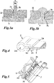
- the process of H exertvernietens of support frame 3 and distributor element 2 or 2a and 2b is carried out as in the FIGS. 3a and 3b indicated.
- the support frame 3 has to H contemplatvernieten with the respective distributor element 2, 2a and 2b projecting pins 34.
- the respective projecting pin 34 is passed through the respective passage opening 24 or 25 of the tongue-shaped connecting portions 22, 23 of the respective distributor elements 2, 2a and 2b.
- FIG. 3a This is in FIG. 3a shown.
- a part of the projecting pin 34 is melted and thereby fills a part of the tapered through hole 24 and 25 form-fitting, like this FIG. 3b can be removed.
- the tapered shape of the respective passage opening 24 and 25 is FIG. 3a , but also FIG. 3b refer to.
- Due to the hot riveting of holding frame 3 and the respective distributor element 2a and 2b a positive connection, which, however, causes no material connection, is thus produced.
- holding frame 3 and distributor element 2, 2a and 2b are held firmly together.
- Holding frame 3 and distributor element 2, 2a and 2b can thus consist of different materials and, accordingly, the choice of material for holding frame and distribution elements are adapted to their respective function.
- H Hydraulics of support frame 3 and distributor element 2, 2a and 2b
- both can also be non-positively connected to each other, for example via a lock.
- This is exemplary in FIG. 5 shown.
- two latching hooks 35, 36 are arranged on the holding frame 3, which engage in corresponding latching receivers 26, 27 on the distributor element 2 shown here and lock it therein.
- Such a connection between holding frame 3 and distributor element 2 can possibly even be released depending on the configuration of the latch.
- connection profile 20 of the distributor element 2 is not formed here as a mandrel profile, but thornless connector profile.
- a media line for transporting the heat exchange medium can be inserted into this thornless connector profile and latched therein.
- a latching connection in particular in the form of snap hooks or latching hooks, can be used as an alternative to that described in US Pat FIG. 5 shown between holding frame 3 and distributor element 2, for example, by engaging arranged on the holding frame 3 latching hooks in corresponding openings which are arranged in projecting portions of the distributor element 2, are provided. It is also possible to provide latching elements provided with the support frame 3, which engage over a portion of the respective distributor element 2 and engage around this grip around this. There are also other types of latching of holding frame 3 and distributor element 2 to each other also possible. Accordingly, the suitable for the particular application connection between the holding frame 3 and distribution element 2 can be selected.
- the distributor element 2 can be connected to the heat exchanger element 4 by gluing.
- the distributor element 2 has two connecting sections 28, 29, which extend approximately parallel, of the respective receiving section 21.
- An edge-side portion 40 of the heat exchanger element 4 is inserted between the two connecting portions 28, 29 and glued there. This is in FIG. 4 indicated.
- the in FIG. 4 Also indicated, extending through the heat exchanger element 4 through channels 41 in flow communication with the inner flow space 200 of the distributor element 2.
- the provision of such an adhesive joint of the heat exchanger element 4 and distributor element 2 is particularly suitable when the distributor element 2 consists of polyamide. Should be in contrast Heat exchanger element 4 and distributor element 2 are connected by hot caulking, the surface of the existing aluminum heat exchanger element 4 is advantageously roughened before to allow a hot caulking with the plastic material of the distributor element 2.
- the distributor element 2 In the region of its receiving section 21, it also has a stop element 121 for abutting the sealing element 6 in the distributor element 2.
- the distributor elements 2 or 2a or 2b may have means for controlling the flow of the heat exchanger medium within these, in particular webs, jibs etc.
- the holding frame 3 has at least one holding and / or guide device 7 for holding and / or guiding the electrical leads 8, 9 of the thermoelectric element 5.
- the holding frame 3 has at least one holding and / or guide device 7 for holding and / or guiding the electrical leads 8, 9 of the thermoelectric element 5.
- FIG. 1 is such a support and / or guide means 7 for electrical leads 8, 9 formed by one of the connecting webs of the support frame 3.
- Mounting and / or guide device 7 for the electrical leads 8, 9 are provided on the support frame 3.
- thermoelectric element such as in particular a Peltier element at least one heat exchanger element for heat exchange with the thermoelectric element and at least one distributor element for supplying and removing a heat exchanger medium
- at least one holding frame for holding the at least one heat exchanger element and the at least one thermoelectric element, which are arranged in particular adjacent to the heat exchanger element, is provided
- the at least one distributor element is or can be connected to the at least one heat exchanger element and with the at least one holding frame.
Landscapes
- Engineering & Computer Science (AREA)
- Physics & Mathematics (AREA)
- Thermal Sciences (AREA)
- Mechanical Engineering (AREA)
- General Engineering & Computer Science (AREA)
- Transportation (AREA)
- Geometry (AREA)
- Air-Conditioning For Vehicles (AREA)
Applications Claiming Priority (1)
| Application Number | Priority Date | Filing Date | Title |
|---|---|---|---|
| DE102018002980.9A DE102018002980A1 (de) | 2018-04-12 | 2018-04-12 | Wärmetauscher-Einheit |
Publications (2)
| Publication Number | Publication Date |
|---|---|
| EP3553450A1 true EP3553450A1 (fr) | 2019-10-16 |
| EP3553450B1 EP3553450B1 (fr) | 2021-05-26 |
Family
ID=66102844
Family Applications (1)
| Application Number | Title | Priority Date | Filing Date |
|---|---|---|---|
| EP19000173.5A Active EP3553450B1 (fr) | 2018-04-12 | 2019-04-08 | Unité d'échangeur de chaleur |
Country Status (2)
| Country | Link |
|---|---|
| EP (1) | EP3553450B1 (fr) |
| DE (1) | DE102018002980A1 (fr) |
Families Citing this family (3)
| Publication number | Priority date | Publication date | Assignee | Title |
|---|---|---|---|---|
| EP4002970A1 (fr) | 2020-11-23 | 2022-05-25 | Voss Automotive GmbH | Agencement pourvu de boîtier destiné à la réception d'un composant électronique exothermique et pourvu de système de refroidissement de celui-ci |
| DE102022001004A1 (de) | 2022-03-23 | 2023-09-28 | Voss Automotive Gmbh | Kühlanordnung |
| DE102024203880A1 (de) * | 2024-04-25 | 2025-10-30 | Robert Bosch Gesellschaft mit beschränkter Haftung | Kältemittelverteiler für einen Kältemittelkreislauf, Kältemittelkreislauf und Fahrzeug |
Citations (4)
| Publication number | Priority date | Publication date | Assignee | Title |
|---|---|---|---|---|
| US5584183A (en) * | 1994-02-18 | 1996-12-17 | Solid State Cooling Systems | Thermoelectric heat exchanger |
| WO2010112571A2 (fr) * | 2009-04-02 | 2010-10-07 | Avl List Gmbh | Dispositif générateur thermoélectrique |
| DE102013101176A1 (de) * | 2013-02-06 | 2014-08-07 | Cybio Ag | Kühlbox mit einem mit röhrchenförmigen Gefäßen bestückten Rack zum automatischen Befüllen mit einem Pipettierautomaten |
| WO2016050588A1 (fr) | 2014-09-30 | 2016-04-07 | Mahle International Gmbh | Dispositif thermoélectrique |
Family Cites Families (2)
| Publication number | Priority date | Publication date | Assignee | Title |
|---|---|---|---|---|
| DE202010011016U1 (de) * | 2010-08-04 | 2011-10-10 | Ingo Schehr | Elektrisches Heizmodul mit PTC-Element zum elektrischen Erwärmen eines Luftstroms |
| DE102016009490A1 (de) * | 2016-08-05 | 2018-02-08 | Gentherm Gmbh | Befestigungseinrichtung für eine oder mehrere thermoelektrische Vorrichtungen |
-
2018
- 2018-04-12 DE DE102018002980.9A patent/DE102018002980A1/de not_active Withdrawn
-
2019
- 2019-04-08 EP EP19000173.5A patent/EP3553450B1/fr active Active
Patent Citations (4)
| Publication number | Priority date | Publication date | Assignee | Title |
|---|---|---|---|---|
| US5584183A (en) * | 1994-02-18 | 1996-12-17 | Solid State Cooling Systems | Thermoelectric heat exchanger |
| WO2010112571A2 (fr) * | 2009-04-02 | 2010-10-07 | Avl List Gmbh | Dispositif générateur thermoélectrique |
| DE102013101176A1 (de) * | 2013-02-06 | 2014-08-07 | Cybio Ag | Kühlbox mit einem mit röhrchenförmigen Gefäßen bestückten Rack zum automatischen Befüllen mit einem Pipettierautomaten |
| WO2016050588A1 (fr) | 2014-09-30 | 2016-04-07 | Mahle International Gmbh | Dispositif thermoélectrique |
Also Published As
| Publication number | Publication date |
|---|---|
| EP3553450B1 (fr) | 2021-05-26 |
| DE102018002980A1 (de) | 2019-10-17 |
Similar Documents
| Publication | Publication Date | Title |
|---|---|---|
| EP2744034B1 (fr) | Agencement d'échangeur thermique | |
| EP1921896B1 (fr) | Elément produisant de la chaleur pour dispositif chauffant électrique et son procédé de fabrication | |
| DE102010029085A1 (de) | Kühlvorrichtung und Verfahren zum Herstellen einer Kühlvorrichtung | |
| EP3553450B1 (fr) | Unité d'échangeur de chaleur | |
| DE102014001975A1 (de) | Batterie für ein Kraftfahrzeug, Kraftfahrzeug und Verfahren zur Herstellung einer Batterie für ein Kraftfahrzeug | |
| EP4406051A1 (fr) | Dissipateur thermique | |
| EP2051314A1 (fr) | Dispositif destiné au stockage d'énergie électrique | |
| DE102019112058B4 (de) | Batteriemodul einer Hochvolt-Batterie für ein Elektrofahrzeug | |
| DE202008017362U1 (de) | Vorrichtung zum Erwärmen oder Kühlen, insbesondere als Teil einer Werkzeugform zur Verarbeitung plastischer Massen, wie Kunststoffspritzgießform | |
| EP2297539B1 (fr) | Refroidisseur à plaques pour liquides | |
| WO2022017775A1 (fr) | Corps de transfert de chaleur | |
| DE102011104433A1 (de) | Energiespeichermodul für eine Vorrichtung zur Spannungsversorgung und Verfahren zum Herstellen eines solchen Energiespeichermoduls | |
| DE20121112U1 (de) | Sammelkasten für einen Wärmeaustauscher, insbesondere an Kraftfahrzeugen | |
| DE10393269T5 (de) | Kühlvorrichtung für ein motorisiertes Fahrzeug | |
| DE102019104405B4 (de) | Kupplung zum Verbinden von Kühlkreislaufabschnitten, Kühlkreislauf mit einer solchen und Kraftfahrzeug mit einem solchen Kühlkreislauf | |
| EP3799267A1 (fr) | Dispositif d'entraînement électrique et procédé de fabrication d'un échangeur de chaleur, en particulier destiné à l'utilisation dans un dispositif d'entraînement électrique | |
| EP2386402B1 (fr) | Buse à canal chaud et outil de moulage par injection doté d'une buse à canal chaud | |
| EP3067603B1 (fr) | Vanne hydraulique | |
| DE10203239A1 (de) | Kühlbaustein | |
| DE102019105984B3 (de) | Dichtring zur Verbindung von zwei fluidführenden Elementen, Kühlsystem mit einem solchen Dichtring für eine Traktionsbatterie eines elektrisch betriebenen Fahrzeugs und Verfahren zum Herstellen eines solchen Kühlsystems | |
| EP1506576A1 (fr) | Dispositifs de refroidissement pour refroidir des composants electriques, module constitue d'un dispositif de refroidissement et de composants electriques, ensemble compose d'un dispositif de refroidissement ou d'un module et d'un support | |
| WO2018024411A1 (fr) | Système de régulation de la température d'un accumulateur | |
| DE102021124066B3 (de) | Batterieanordnung | |
| EP2654120A1 (fr) | Dispositif destiné au refroidissement de la batterie d'un véhicule | |
| DE102010039676B4 (de) | Kühlsystem zum Kühlen von Elektronikkomponenten |
Legal Events
| Date | Code | Title | Description |
|---|---|---|---|
| PUAI | Public reference made under article 153(3) epc to a published international application that has entered the european phase |
Free format text: ORIGINAL CODE: 0009012 |
|
| STAA | Information on the status of an ep patent application or granted ep patent |
Free format text: STATUS: THE APPLICATION HAS BEEN PUBLISHED |
|
| AK | Designated contracting states |
Kind code of ref document: A1 Designated state(s): AL AT BE BG CH CY CZ DE DK EE ES FI FR GB GR HR HU IE IS IT LI LT LU LV MC MK MT NL NO PL PT RO RS SE SI SK SM TR |
|
| AX | Request for extension of the european patent |
Extension state: BA ME |
|
| STAA | Information on the status of an ep patent application or granted ep patent |
Free format text: STATUS: REQUEST FOR EXAMINATION WAS MADE |
|
| 17P | Request for examination filed |
Effective date: 20191125 |
|
| RBV | Designated contracting states (corrected) |
Designated state(s): AL AT BE BG CH CY CZ DE DK EE ES FI FR GB GR HR HU IE IS IT LI LT LU LV MC MK MT NL NO PL PT RO RS SE SI SK SM TR |
|
| GRAP | Despatch of communication of intention to grant a patent |
Free format text: ORIGINAL CODE: EPIDOSNIGR1 |
|
| STAA | Information on the status of an ep patent application or granted ep patent |
Free format text: STATUS: GRANT OF PATENT IS INTENDED |
|
| INTG | Intention to grant announced |
Effective date: 20200908 |
|
| GRAS | Grant fee paid |
Free format text: ORIGINAL CODE: EPIDOSNIGR3 |
|
| GRAJ | Information related to disapproval of communication of intention to grant by the applicant or resumption of examination proceedings by the epo deleted |
Free format text: ORIGINAL CODE: EPIDOSDIGR1 |
|
| GRAL | Information related to payment of fee for publishing/printing deleted |
Free format text: ORIGINAL CODE: EPIDOSDIGR3 |
|
| STAA | Information on the status of an ep patent application or granted ep patent |
Free format text: STATUS: REQUEST FOR EXAMINATION WAS MADE |
|
| GRAP | Despatch of communication of intention to grant a patent |
Free format text: ORIGINAL CODE: EPIDOSNIGR1 |
|
| STAA | Information on the status of an ep patent application or granted ep patent |
Free format text: STATUS: GRANT OF PATENT IS INTENDED |
|
| INTC | Intention to grant announced (deleted) | ||
| INTG | Intention to grant announced |
Effective date: 20201221 |
|
| GRAJ | Information related to disapproval of communication of intention to grant by the applicant or resumption of examination proceedings by the epo deleted |
Free format text: ORIGINAL CODE: EPIDOSDIGR1 |
|
| GRAL | Information related to payment of fee for publishing/printing deleted |
Free format text: ORIGINAL CODE: EPIDOSDIGR3 |
|
| STAA | Information on the status of an ep patent application or granted ep patent |
Free format text: STATUS: REQUEST FOR EXAMINATION WAS MADE |
|
| GRAP | Despatch of communication of intention to grant a patent |
Free format text: ORIGINAL CODE: EPIDOSNIGR1 |
|
| STAA | Information on the status of an ep patent application or granted ep patent |
Free format text: STATUS: GRANT OF PATENT IS INTENDED |
|
| INTC | Intention to grant announced (deleted) | ||
| INTG | Intention to grant announced |
Effective date: 20210316 |
|
| GRAA | (expected) grant |
Free format text: ORIGINAL CODE: 0009210 |
|
| STAA | Information on the status of an ep patent application or granted ep patent |
Free format text: STATUS: THE PATENT HAS BEEN GRANTED |
|
| AK | Designated contracting states |
Kind code of ref document: B1 Designated state(s): AL AT BE BG CH CY CZ DE DK EE ES FI FR GB GR HR HU IE IS IT LI LT LU LV MC MK MT NL NO PL PT RO RS SE SI SK SM TR |
|
| REG | Reference to a national code |
Ref country code: GB Ref legal event code: FG4D Free format text: NOT ENGLISH |
|
| REG | Reference to a national code |
Ref country code: CH Ref legal event code: EP |
|
| REG | Reference to a national code |
Ref country code: AT Ref legal event code: REF Ref document number: 1396651 Country of ref document: AT Kind code of ref document: T Effective date: 20210615 |
|
| REG | Reference to a national code |
Ref country code: DE Ref legal event code: R096 Ref document number: 502019001460 Country of ref document: DE |
|
| REG | Reference to a national code |
Ref country code: IE Ref legal event code: FG4D Free format text: LANGUAGE OF EP DOCUMENT: GERMAN |
|
| REG | Reference to a national code |
Ref country code: LT Ref legal event code: MG9D |
|
| PG25 | Lapsed in a contracting state [announced via postgrant information from national office to epo] |
Ref country code: HR Free format text: LAPSE BECAUSE OF FAILURE TO SUBMIT A TRANSLATION OF THE DESCRIPTION OR TO PAY THE FEE WITHIN THE PRESCRIBED TIME-LIMIT Effective date: 20210526 Ref country code: LT Free format text: LAPSE BECAUSE OF FAILURE TO SUBMIT A TRANSLATION OF THE DESCRIPTION OR TO PAY THE FEE WITHIN THE PRESCRIBED TIME-LIMIT Effective date: 20210526 Ref country code: FI Free format text: LAPSE BECAUSE OF FAILURE TO SUBMIT A TRANSLATION OF THE DESCRIPTION OR TO PAY THE FEE WITHIN THE PRESCRIBED TIME-LIMIT Effective date: 20210526 Ref country code: BG Free format text: LAPSE BECAUSE OF FAILURE TO SUBMIT A TRANSLATION OF THE DESCRIPTION OR TO PAY THE FEE WITHIN THE PRESCRIBED TIME-LIMIT Effective date: 20210826 |
|
| REG | Reference to a national code |
Ref country code: NL Ref legal event code: MP Effective date: 20210526 |
|
| PG25 | Lapsed in a contracting state [announced via postgrant information from national office to epo] |
Ref country code: GR Free format text: LAPSE BECAUSE OF FAILURE TO SUBMIT A TRANSLATION OF THE DESCRIPTION OR TO PAY THE FEE WITHIN THE PRESCRIBED TIME-LIMIT Effective date: 20210827 Ref country code: IS Free format text: LAPSE BECAUSE OF FAILURE TO SUBMIT A TRANSLATION OF THE DESCRIPTION OR TO PAY THE FEE WITHIN THE PRESCRIBED TIME-LIMIT Effective date: 20210926 Ref country code: PT Free format text: LAPSE BECAUSE OF FAILURE TO SUBMIT A TRANSLATION OF THE DESCRIPTION OR TO PAY THE FEE WITHIN THE PRESCRIBED TIME-LIMIT Effective date: 20210927 Ref country code: RS Free format text: LAPSE BECAUSE OF FAILURE TO SUBMIT A TRANSLATION OF THE DESCRIPTION OR TO PAY THE FEE WITHIN THE PRESCRIBED TIME-LIMIT Effective date: 20210526 Ref country code: SE Free format text: LAPSE BECAUSE OF FAILURE TO SUBMIT A TRANSLATION OF THE DESCRIPTION OR TO PAY THE FEE WITHIN THE PRESCRIBED TIME-LIMIT Effective date: 20210526 Ref country code: NO Free format text: LAPSE BECAUSE OF FAILURE TO SUBMIT A TRANSLATION OF THE DESCRIPTION OR TO PAY THE FEE WITHIN THE PRESCRIBED TIME-LIMIT Effective date: 20210826 Ref country code: LV Free format text: LAPSE BECAUSE OF FAILURE TO SUBMIT A TRANSLATION OF THE DESCRIPTION OR TO PAY THE FEE WITHIN THE PRESCRIBED TIME-LIMIT Effective date: 20210526 Ref country code: PL Free format text: LAPSE BECAUSE OF FAILURE TO SUBMIT A TRANSLATION OF THE DESCRIPTION OR TO PAY THE FEE WITHIN THE PRESCRIBED TIME-LIMIT Effective date: 20210526 |
|
| PG25 | Lapsed in a contracting state [announced via postgrant information from national office to epo] |
Ref country code: NL Free format text: LAPSE BECAUSE OF FAILURE TO SUBMIT A TRANSLATION OF THE DESCRIPTION OR TO PAY THE FEE WITHIN THE PRESCRIBED TIME-LIMIT Effective date: 20210526 |
|
| PG25 | Lapsed in a contracting state [announced via postgrant information from national office to epo] |
Ref country code: CZ Free format text: LAPSE BECAUSE OF FAILURE TO SUBMIT A TRANSLATION OF THE DESCRIPTION OR TO PAY THE FEE WITHIN THE PRESCRIBED TIME-LIMIT Effective date: 20210526 Ref country code: DK Free format text: LAPSE BECAUSE OF FAILURE TO SUBMIT A TRANSLATION OF THE DESCRIPTION OR TO PAY THE FEE WITHIN THE PRESCRIBED TIME-LIMIT Effective date: 20210526 Ref country code: SM Free format text: LAPSE BECAUSE OF FAILURE TO SUBMIT A TRANSLATION OF THE DESCRIPTION OR TO PAY THE FEE WITHIN THE PRESCRIBED TIME-LIMIT Effective date: 20210526 Ref country code: RO Free format text: LAPSE BECAUSE OF FAILURE TO SUBMIT A TRANSLATION OF THE DESCRIPTION OR TO PAY THE FEE WITHIN THE PRESCRIBED TIME-LIMIT Effective date: 20210526 Ref country code: SK Free format text: LAPSE BECAUSE OF FAILURE TO SUBMIT A TRANSLATION OF THE DESCRIPTION OR TO PAY THE FEE WITHIN THE PRESCRIBED TIME-LIMIT Effective date: 20210526 Ref country code: ES Free format text: LAPSE BECAUSE OF FAILURE TO SUBMIT A TRANSLATION OF THE DESCRIPTION OR TO PAY THE FEE WITHIN THE PRESCRIBED TIME-LIMIT Effective date: 20210526 Ref country code: EE Free format text: LAPSE BECAUSE OF FAILURE TO SUBMIT A TRANSLATION OF THE DESCRIPTION OR TO PAY THE FEE WITHIN THE PRESCRIBED TIME-LIMIT Effective date: 20210526 |
|
| REG | Reference to a national code |
Ref country code: DE Ref legal event code: R097 Ref document number: 502019001460 Country of ref document: DE |
|
| PLBE | No opposition filed within time limit |
Free format text: ORIGINAL CODE: 0009261 |
|
| STAA | Information on the status of an ep patent application or granted ep patent |
Free format text: STATUS: NO OPPOSITION FILED WITHIN TIME LIMIT |
|
| 26N | No opposition filed |
Effective date: 20220301 |
|
| PG25 | Lapsed in a contracting state [announced via postgrant information from national office to epo] |
Ref country code: IS Free format text: LAPSE BECAUSE OF FAILURE TO SUBMIT A TRANSLATION OF THE DESCRIPTION OR TO PAY THE FEE WITHIN THE PRESCRIBED TIME-LIMIT Effective date: 20210926 Ref country code: AL Free format text: LAPSE BECAUSE OF FAILURE TO SUBMIT A TRANSLATION OF THE DESCRIPTION OR TO PAY THE FEE WITHIN THE PRESCRIBED TIME-LIMIT Effective date: 20210526 |
|
| PG25 | Lapsed in a contracting state [announced via postgrant information from national office to epo] |
Ref country code: IT Free format text: LAPSE BECAUSE OF FAILURE TO SUBMIT A TRANSLATION OF THE DESCRIPTION OR TO PAY THE FEE WITHIN THE PRESCRIBED TIME-LIMIT Effective date: 20210526 |
|
| REG | Reference to a national code |
Ref country code: CH Ref legal event code: PL |
|
| REG | Reference to a national code |
Ref country code: BE Ref legal event code: MM Effective date: 20220430 |
|
| PG25 | Lapsed in a contracting state [announced via postgrant information from national office to epo] |
Ref country code: MC Free format text: LAPSE BECAUSE OF FAILURE TO SUBMIT A TRANSLATION OF THE DESCRIPTION OR TO PAY THE FEE WITHIN THE PRESCRIBED TIME-LIMIT Effective date: 20210526 Ref country code: LU Free format text: LAPSE BECAUSE OF NON-PAYMENT OF DUE FEES Effective date: 20220408 Ref country code: LI Free format text: LAPSE BECAUSE OF NON-PAYMENT OF DUE FEES Effective date: 20220430 Ref country code: CH Free format text: LAPSE BECAUSE OF NON-PAYMENT OF DUE FEES Effective date: 20220430 |
|
| PG25 | Lapsed in a contracting state [announced via postgrant information from national office to epo] |
Ref country code: BE Free format text: LAPSE BECAUSE OF NON-PAYMENT OF DUE FEES Effective date: 20220430 |
|
| PG25 | Lapsed in a contracting state [announced via postgrant information from national office to epo] |
Ref country code: IE Free format text: LAPSE BECAUSE OF NON-PAYMENT OF DUE FEES Effective date: 20220408 |
|
| P01 | Opt-out of the competence of the unified patent court (upc) registered |
Effective date: 20230531 |
|
| GBPC | Gb: european patent ceased through non-payment of renewal fee |
Effective date: 20230408 |
|
| PG25 | Lapsed in a contracting state [announced via postgrant information from national office to epo] |
Ref country code: GB Free format text: LAPSE BECAUSE OF NON-PAYMENT OF DUE FEES Effective date: 20230408 |
|
| PG25 | Lapsed in a contracting state [announced via postgrant information from national office to epo] |
Ref country code: GB Free format text: LAPSE BECAUSE OF NON-PAYMENT OF DUE FEES Effective date: 20230408 |
|
| PG25 | Lapsed in a contracting state [announced via postgrant information from national office to epo] |
Ref country code: HU Free format text: LAPSE BECAUSE OF FAILURE TO SUBMIT A TRANSLATION OF THE DESCRIPTION OR TO PAY THE FEE WITHIN THE PRESCRIBED TIME-LIMIT; INVALID AB INITIO Effective date: 20190408 |
|
| PG25 | Lapsed in a contracting state [announced via postgrant information from national office to epo] |
Ref country code: MK Free format text: LAPSE BECAUSE OF FAILURE TO SUBMIT A TRANSLATION OF THE DESCRIPTION OR TO PAY THE FEE WITHIN THE PRESCRIBED TIME-LIMIT Effective date: 20210526 Ref country code: CY Free format text: LAPSE BECAUSE OF FAILURE TO SUBMIT A TRANSLATION OF THE DESCRIPTION OR TO PAY THE FEE WITHIN THE PRESCRIBED TIME-LIMIT Effective date: 20210526 |
|
| PG25 | Lapsed in a contracting state [announced via postgrant information from national office to epo] |
Ref country code: TR Free format text: LAPSE BECAUSE OF FAILURE TO SUBMIT A TRANSLATION OF THE DESCRIPTION OR TO PAY THE FEE WITHIN THE PRESCRIBED TIME-LIMIT Effective date: 20210526 |
|
| PG25 | Lapsed in a contracting state [announced via postgrant information from national office to epo] |
Ref country code: MT Free format text: LAPSE BECAUSE OF FAILURE TO SUBMIT A TRANSLATION OF THE DESCRIPTION OR TO PAY THE FEE WITHIN THE PRESCRIBED TIME-LIMIT Effective date: 20210526 |
|
| REG | Reference to a national code |
Ref country code: AT Ref legal event code: MM01 Ref document number: 1396651 Country of ref document: AT Kind code of ref document: T Effective date: 20240408 |
|
| PGFP | Annual fee paid to national office [announced via postgrant information from national office to epo] |
Ref country code: DE Payment date: 20250403 Year of fee payment: 7 |
|
| PG25 | Lapsed in a contracting state [announced via postgrant information from national office to epo] |
Ref country code: AT Free format text: LAPSE BECAUSE OF NON-PAYMENT OF DUE FEES Effective date: 20240408 |
|
| PGFP | Annual fee paid to national office [announced via postgrant information from national office to epo] |
Ref country code: AT Payment date: 20260410 Year of fee payment: 5 |
|
| PGFP | Annual fee paid to national office [announced via postgrant information from national office to epo] |
Ref country code: FR Payment date: 20260106 Year of fee payment: 8 |