EP3553564A1 - Capteur mesurant la distance - Google Patents
Capteur mesurant la distance Download PDFInfo
- Publication number
- EP3553564A1 EP3553564A1 EP19163963.2A EP19163963A EP3553564A1 EP 3553564 A1 EP3553564 A1 EP 3553564A1 EP 19163963 A EP19163963 A EP 19163963A EP 3553564 A1 EP3553564 A1 EP 3553564A1
- Authority
- EP
- European Patent Office
- Prior art keywords
- sensor
- light beam
- light
- transmitted light
- reflected
- Prior art date
- Legal status (The legal status is an assumption and is not a legal conclusion. Google has not performed a legal analysis and makes no representation as to the accuracy of the status listed.)
- Granted
Links
Images


Classifications
-
- G—PHYSICS
- G01—MEASURING; TESTING
- G01S—RADIO DIRECTION-FINDING; RADIO NAVIGATION; DETERMINING DISTANCE OR VELOCITY BY USE OF RADIO WAVES; LOCATING OR PRESENCE-DETECTING BY USE OF THE REFLECTION OR RERADIATION OF RADIO WAVES; ANALOGOUS ARRANGEMENTS USING OTHER WAVES
- G01S17/00—Systems using the reflection or reradiation of electromagnetic waves other than radio waves, e.g. lidar systems
- G01S17/02—Systems using the reflection of electromagnetic waves other than radio waves
- G01S17/06—Systems determining position data of a target
- G01S17/42—Simultaneous measurement of distance and other co-ordinates
-
- G—PHYSICS
- G01—MEASURING; TESTING
- G01S—RADIO DIRECTION-FINDING; RADIO NAVIGATION; DETERMINING DISTANCE OR VELOCITY BY USE OF RADIO WAVES; LOCATING OR PRESENCE-DETECTING BY USE OF THE REFLECTION OR RERADIATION OF RADIO WAVES; ANALOGOUS ARRANGEMENTS USING OTHER WAVES
- G01S7/00—Details of systems according to groups G01S13/00, G01S15/00, G01S17/00
- G01S7/48—Details of systems according to groups G01S13/00, G01S15/00, G01S17/00 of systems according to group G01S17/00
- G01S7/481—Constructional features, e.g. arrangements of optical elements
- G01S7/4811—Constructional features, e.g. arrangements of optical elements common to transmitter and receiver
- G01S7/4812—Constructional features, e.g. arrangements of optical elements common to transmitter and receiver transmitted and received beams following a coaxial path
-
- G—PHYSICS
- G01—MEASURING; TESTING
- G01S—RADIO DIRECTION-FINDING; RADIO NAVIGATION; DETERMINING DISTANCE OR VELOCITY BY USE OF RADIO WAVES; LOCATING OR PRESENCE-DETECTING BY USE OF THE REFLECTION OR RERADIATION OF RADIO WAVES; ANALOGOUS ARRANGEMENTS USING OTHER WAVES
- G01S7/00—Details of systems according to groups G01S13/00, G01S15/00, G01S17/00
- G01S7/48—Details of systems according to groups G01S13/00, G01S15/00, G01S17/00 of systems according to group G01S17/00
- G01S7/481—Constructional features, e.g. arrangements of optical elements
- G01S7/4811—Constructional features, e.g. arrangements of optical elements common to transmitter and receiver
- G01S7/4813—Housing arrangements
Definitions
- the present invention relates to a distance-measuring sensor comprising a light source for generating a transmitted light beam, at least one focusing element for detecting reflected light of the transmitted light beam reflected from an object, and a detection element provided for detecting the light passing through the focusing element is detected.
- TOF sensor time-of-flight sensor
- the transit time of the light is determined, for example between the light source and the detection element, to determine the distance between the sensor and the time of flight and the speed of light Measure object on which the transmitted light beam is reflected or remitted.
- the running time can be, for example, the duration of a light pulse.
- the phase shift of a modulated signal is evaluated, but this also corresponds to an at least indirect determination of the light transit time. In this respect, such an evaluation of a phase shift in the present text is subsumed under the term light transit time determination.
- Such TOF sensors are used, for example, for object recognition or in scanners, wherein a predetermined spatial area is scanned, for example by means of a laser as the light source.
- the light source and the focusing element are each arranged in a separate transmitting area or receiving area, wherein the light source and the focusing element are from each other and the transmitted light beam is thus optically isolated from the focusing element and the detection element within the sensor. Due to the spatial Separation of the transmission and reception range, which is achieved for example with a divider, such a sensor is also referred to as a sensor with "double eye".
- the divider usually extends only to a front window of the sensor, which closes a housing of the sensor with respect to the outer space.
- both the transmitted light beam and a reception path of the light which is to be detected by means of the focusing element run through the front pane.
- optical crosstalk between the transmitted light beam and the focussing element may occur via the front screen.
- light of the transmitted light beam passes directly through the front screen to the focusing element and thus to the detection element of the sensor, without it being previously reflected on an object outside the sensor.
- This crosstalk falsifies the measurement signal which is generated by means of the detection element and leads to systematic measurement errors.
- either the focusing element in the direction of the windscreen extension is arranged as far away from the transmitted light beam, or there are two separate windscreens for the transmission and the reception of the sensor , In both cases, a triangulation effect occurs, wherein two sides of the triangle are formed by the transmitted light beam and the receiving path between the object and the sensor and the third side of the triangle corresponds to the distance between the focus of the focusing element and the transmitted light beam.
- Such a triangulation causes a spot of light, which by means of the focusing element by the detection and focusing of the reflected from the object or remitted light is formed on the detection element, shifts within a certain range as the distance between the object and the sensor changes. Furthermore, by the triangulation, ie by the always present angle of inclination between the normal to the windshield and the receiving path, multiple scattering within the windscreen occur, which represent a disturbing effect for the measurement signal of the sensor.
- the detection element comprises a field of receiving cells arranged, for example, on a square surface
- a part of the cells receives only stray light which has not been reflected or remitted as desired by the object.
- the signal-to-noise ratio of the measurement signal generated by the detection element deteriorates. Due to the shift of the light spot, which is caused by the triangulation with a change in the distance between the object and the sensor, it is also difficult to subsequently separate the measurement signal, which results from the detected reflected or remitted light, from the signal. which is caused by the unwanted scattered light.
- An object of the invention is to further develop a sensor of the type mentioned in such a way that the intensity of unwanted light, which enters the sensor in addition to the reflected or remitted light to be detected, is minimized.
- a distance-measuring sensor having the features of claim 1.
- a transmitted light beam which is generated by means of a light source of the sensor, and a reception path of light of the transmitted light beam, which is reflected or remitted on an object and is detected by a focusing element of the sensor, are aligned substantially parallel to each other in front of the focusing element.
- the transmitted light beam and the reception path of the light to be detected in front of the focusing element are preferably aligned completely parallel to each other.
- the sensor according to the invention further comprises a detection element for detecting the light detected by the focusing element and an evaluation unit, which is designed to determine the transit time of the light between the light source and the detection element. On the basis of the determined transit time, the determination of the distance between the sensor and the object is also carried out, as described above.
- the running time can be, for example, the duration of a light pulse.
- the phase shift of a modulated signal is evaluated, but this also corresponds to an at least indirect determination of the light transit time. In this respect, such an evaluation of a phase shift in the present text is subsumed under the term light transit time determination.
- the parallel alignment of the receive path of the light to be detected with the transmitted light beam minimizes the above-described effects of triangulation, i. the effects mentioned above, which are caused by an inclination angle between the transmitted light beam and the receiving path.
- the lateral distance between the transmitted light beam and a focal point of the focusing element is preferably as small as possible so that the transmitted light beam extends almost through the focal point or through a focus region of the focusing element.
- the focusing element preferably surrounds an area through which the transmitted light beam passes.
- the focusing element illuminates a light spot on the detection element whose position is almost unchanged when the distance between the sensor and an object varies, at which the transmitted light beam reflected or remittiert.
- the detection element can be precisely arranged or adjusted at the end of the reception path, whereby the size of a measurement signal generated by the detection element is maximized and its signal-to-noise ratio is improved.
- the parallel alignment between the transmitted light beam and the reception path allows a large focal length of the focusing element.
- the scanning range is increased, in which a distance measurement by means of the sensor is possible.
- an intermediate image can be generated in a plane between the focusing element and the detection element.
- the beam path between the focusing element and the detection element can be precisely determined.
- the intensity of the light reaching the detection element can be optimized so that the signal-to-noise ratio of the signal generated by the detection element is further improved.
- the detection element comprises an array of receiving cells
- an active region or "region of interest (ROI)" can be defined thereon, since the position of the region or light spot illuminated by the focusing element on the detection element is due to the parallel alignment between the transmitted light beam and the reception path does not change.
- ROI region of interest
- only those receiving cells of the detection element are activated, which are actually in the region of the light spot, while such receiving cells are deactivated, which are not reached by the detected reflected or remitted light of the transmitted light beam, but instead absorb only unwanted scattered light. This in turn can improve the signal-to-noise ratio of the measuring signal of the sensor.
- An example of the detection element forming array of receiving elements can due to the precise and almost unchanged position of the detected Light point designed to be smaller than comparable arrays according to the prior art.
- the number of receiving elements to be read is smaller, whereby a data reduction can be achieved.
- the receiving elements can be read out within a shorter period of time due to the reduced number.
- the respectively active region within the array can be flexibly adapted to the changed reception path when exchanging or changing components within the reception path of the light to be detected.
- the transmitted light beam is arranged coaxially with respect to the reception path of the reflected or remitted light to be detected in front of the focusing element. Since the light is detected via the reception path, which is diffusely reflected or remitted on the object, the reception path has a certain width, which is predetermined by the dimensions of the focusing element in order to detect a sufficient light intensity can. In this embodiment, the transmitted light beam thus passes coaxially through the geometric center of the reception path. Such an arrangement further enhances the optical image and signal-to-noise ratio advantages described above.
- the senor further comprises a windshield through which the transmitted light beam and the reflected or remitted light to be detected pass.
- the windshield in this case has a separating element which divides the windshield into a first section through which the transmitted light beam passes, and a second section through which the reflected or remitted light to be detected passes. Furthermore, the separating element extends in this Embodiment in the direction of the transmitted light beam over the entire cross section of the windscreen.
- the separating element By means of the separating element, the receiving path of the sensor in the region of the windshield is completely optically isolated from the transmitted light beam. As a result, the optical crosstalk of light of the transmitted light beam described above via the windshield into the reception path can be prevented. Thus, the separator prevents a portion of the light from the transmitted light beam from passing directly onto the focusing element via the windscreen without being reflected or remitted as desired on an object. By avoiding crosstalk, the intensity of unwanted scattered light in the reception path is thus in turn reduced, so that, conversely, the signal-to-noise ratio of the measurement signal is further improved.
- the separating element is preferably arranged completely circumferentially around the transmitted light beam.
- the above-described optical isolation between the transmitted light beam and the reception path or the focusing element is optimized.
- a completely circumferential separating element can be produced simply and cost-effectively, for example in the form of a tube or tube.
- the surface of the second portion of the windshield may be arranged at right angles with respect to the transmitted light beam.
- the surface of the first portion of the windshield is inclined with respect to the surface of the second portion.
- an angle of inclination between the respective surfaces of the first or second section of the windshield preferably has a size of at most 5 degrees and particularly preferably a size of at most 1 degree.
- a reflection of light from the transmitted light beam on the windscreen back into the light source can be prevented.
- the light source is designed as a laser, since influencing the laser power is excluded by such a return reflection when the first portion of the windscreen is arranged inclined.
- a possibly existing monitor diode in such a laser at an inclination of the first portion of the windscreen is also not affected by a back reflection.
- generation of spurious light rays due to further reflection on shiny parts within the light source is prevented.
- the first and / or the second portion of the windshield and / or the separating element are separate parts, which are interconnected by ultrasonic welding, wherein the windshield and the separating element are advantageously made of plastic.
- the first portion of the windshield, the second portion of the windshield and the separating element are each separate parts. This allows the windshield and separator to be fabricated together as a pre-assembly, which can then be mounted inside the sensor.
- the first and second portions of the windshield and the separator may be manufactured by an injection molding process.
- the injection molding process is in particular a two-component injection molding process.
- a light guide element between the focusing element and the detection element is arranged.
- a light guide element causes an increase in the intensity of the light which reaches the detection element, since in the presence of a light guide less light from the receiving path between the focusing element and the detection element can be scattered out.
- the optical can be Precise adjustment of the light to be detected to a desired area of the detection element by means of the light guide element, which in turn can improve the quality of the measurement signal.
- the focusing element is preferably designed as a mirror, which is preferably a concave mirror.
- the mirror allows an adaptation of the reception path of the light to be detected to a space available within the sensor.
- the space within a housing of the sensor in the transverse direction of the transmitted light beam can be better utilized with a mirror than e.g. with a lens.
- the use of a mirror allows the use of larger focal lengths of the focusing element as compared to a lens.
- the magnification of the focal length reduces a viewing area within which the light reflected or remitted on the object is detected. This in turn improves the signal-to-noise ratio of the measuring signal of the sensor.
- a further improvement of the signal-to-noise ratio of the measurement signal of the sensor can be achieved by advantageously arranging a bandpass filter between the focusing element and the detection element.
- the bandpass filter preferably has a transmission range for light wavelengths which comprises the wavelength of the light emitted by the light source. Undesired stray light with wavelengths outside the transmission range, on the other hand, can be absorbed by the bandpass filter and not contribute to the sensor's measurement signal.
- a diaphragm is arranged in a plane in which the focusing element generates an intermediate image.
- the image of the light to be detected is further improved on the detection element, since unwanted scattered light in the plane of the intermediate image is hidden at a suitable location at which the receiving path for the light to be detected due to the focus on the intermediate image has minimal dimensions.
- the detection element preferably comprises at least one avalanche photodiode. Such a photodiode is particularly suitable for detecting low light intensities.
- the detection element is preferably designed as a field of single-photon avalanche photodiodes (SPAD array).
- SPAD array single-photon avalanche photodiodes
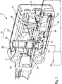
- Fig. 1 shows a sensor 11 according to the invention
- the housing 13 is cut in the longitudinal direction, in a perspective view.
- a laser diode 15 is arranged, which serves as a light source of the sensor 11 and above which a lens 17 is arranged.
- a transmitted light beam 19 is generated, which in Fig. 2 is shown schematically as a dotted line.
- the transmitted light beam 19 passes through a transmitter ear 21 and then exits through a front screen 23 from the sensor 11, which terminates the housing 13 with respect to an exterior space.
- the transmitter tube 21 divides the front screen 23 into a first section 25, which is arranged inside the transmitter tube 21 and through which the transmitted light beam 19 passes, and a second section 27 outside the transmitter tube 21.
- the transmitter tube 21 thus forms a separating element in the region of the front screen 23 29 between the first portion 25 and the second portion 27 of the windscreen 23rd
- the first portion 25 of the windshield with respect to the second portion 27 is arranged slightly inclined.
- the surfaces of the first portion 25 and the second portion 27 include an angle 30 of about 1 degree.
- the transmitted light beam 19 When the transmitted light beam 19 impinges on an object (not shown) outside the housing 13 of the sensor 11, the transmitted light beam 19 is reflected or remitted thereon. A portion of this light passes through a receiving path 31 back to the front glass 23 of the sensor 11.
- the receiving path 31 is in Fig. 2 illustrated by way of example with reference to two light beams 33.
- the light reflected or remitted on the object also passes along the receiving path 31 through the front screen 23 to a mirror 35, which represents a focusing element of the sensor 11.
- the sensor 11 is characterized in that the mirror 35 is arranged in the region of the transmitter ear 21 and at least partially surrounds it. How to get in Fig. 1 and 3 can recognize, the mirror 35 extends into areas in the direction of Fig. 1 and 3 lie behind the transmitter ear 21.
- the mirror 35 By this arrangement of the mirror 35, the transmitted light beam 19 and the reception path 31 in the area in front of the mirror 35, ie in Fig. 1 and 3 above the mirror 35, aligned substantially parallel.
- the transmitted light beam 19 in this case runs almost through the focal point of the mirror 35. Due to the parallel alignment of the receiving path 31 and the transmitted light beam 19, the mirror 35 has a large focal length, which is larger than in sensors from the prior art, as a focusing element Use lens.
- the transmitted light beam 19 is completely isolated by means of the transmitter ear 21 completely opposite the mirror 35 and other components of the sensor 11, which are arranged along the receiving path 31.
- a sealing element 37 is additionally arranged for optical isolation.
- the sealing element 37 serves to connect the Transmitter ear 21 with a support member 39 (see. Fig. 2 ), in which the lens 17 is housed.
- the sealing element 37 ensures a tolerance compensation in the arrangement and orientation of the transmitter ear 21st
- the transmitter ear 21 forms the separating element 29 between the first and second sections 25, 27 of the front screen 23
- light from the transmitted light beam 19 is prevented from being reflected or scattered in the front screen 23 within the housing 13 of the sensor 11 into the receiving path 31 and in particular reaches the mirror 35.
- the separating element 29 extends for this purpose over the entire cross section of the windshield 23, i. to its outer surface.
- An "optical crosstalk" between the transmitted light beam 19 and the receiving path 31 is thus prevented by the isolation of the transmitted light beam 19 by means of the transmitter ear 21 and the sealing element 37 and in particular by the separating element 29 between the first and second sections 25, 27 of the front screen 23.
- the focal length of the mirror 35 can be selected such that an intermediate image is generated in a plane in which a diaphragm 41 is arranged.
- a band pass filter 43 Between the mirror 35 and the diaphragm 41, there is further disposed a band pass filter 43 through which only light having a wavelength in a predetermined range passes, which includes the wavelength of the light emitted from the laser diode 15.
- the light detected by the mirror 35 falls onto a light guide element 45, via which the light is finally directed onto a detection element 47.
- the light guide element 45 is aligned almost parallel to the transmitted light beam 19.
- the detection element 47 comprises an array of single-photon avalanche photodiodes, also referred to as a SPAD array (single photon avalanche diode SPAD).
- SPAD array single photon avalanche diode SPAD
- the SPAD array of the detection element 47 is illuminated in a certain area or light spot via the light guide element 45 with light, which is detected by the mirror 35 and light of the transmitted light beam 19, which reflects on an object outside the housing 13 of the sensor 11 or was remitted. Due to the parallel orientation of the transmitted light beam 19 and the receiving path 31, the position of the illuminated area or light spot on the detection element 47 changes only insignificantly when the distance between the sensor 11 and the object changes.
- the mirror 35 surrounds the transmitter ear 21 and thus the transmitted light beam 19 and thus the mirror 35 is arranged as a focusing element of the sensor 11 in the same space below the windscreen 23 as the transmitted light beam 19, the angle between the transmitted light beam 19 and the light beams 33 is minimized, which reach the mirror 35 again along the receiving path 31 after reflection on the object via the front screen 23. Minimizing this angle minimizes triangulation which occurs as a perturbing effect in known sensors in which the transmitted light beam and a focusing element, such as a lens, are spaced and spatially separated in the form of a "double eye". With such a spacing, the reflected light on the object always falls at a certain angle on the front screen of the sensor before it reaches the focusing element.
- the light spot on the detection element which is formed by the focusing element thereon, shifts as the distance between the sensor and the object varies.
- the triangulation disturbing effects may occur, for example, by multiple scattering of light within the windscreen.
- the effects associated with the triangulation due to the parallel alignment of the transmitted light beam 19 and the receiving path 31 are minimized.
- Fig. 1 and 2 shown sensor 11 are the first and second portions 25, 27 of the front screen 23 and the transmitter ear 21 before mounting the sensor 11 initially separate parts. However, these are already connected to each other before assembly of the sensor 11 by means of ultrasonic welding to a pre-assembly, which then with the other elements of the sensor 11 is mounted. From the in Fig. 1 and 2 shown sensor 11 is different in Fig. 3 shown sensor 11 only in that the transmitter tube 21 is made together with the first and second sections 25, 27 by means of a two-component injection molding, before these elements 21, 25 and 27 are connected as a pre-assembly in turn with other components of the sensor 11. In this production of the subassembly by means of two-component injection molding, an inclined arrangement of the first section 25 of the front screen 23 with respect to the second section 27 is provided at an angle 30 of approximately 1 degree.
Landscapes
- Engineering & Computer Science (AREA)
- Physics & Mathematics (AREA)
- Computer Networks & Wireless Communication (AREA)
- General Physics & Mathematics (AREA)
- Radar, Positioning & Navigation (AREA)
- Remote Sensing (AREA)
- Electromagnetism (AREA)
- Optical Radar Systems And Details Thereof (AREA)
- Length Measuring Devices By Optical Means (AREA)
Applications Claiming Priority (1)
| Application Number | Priority Date | Filing Date | Title |
|---|---|---|---|
| DE102018108631.8A DE102018108631A1 (de) | 2018-04-11 | 2018-04-11 | Entfernungsmessender Sensor |
Publications (2)
| Publication Number | Publication Date |
|---|---|
| EP3553564A1 true EP3553564A1 (fr) | 2019-10-16 |
| EP3553564B1 EP3553564B1 (fr) | 2021-05-12 |
Family
ID=65904055
Family Applications (1)
| Application Number | Title | Priority Date | Filing Date |
|---|---|---|---|
| EP19163963.2A Active EP3553564B1 (fr) | 2018-04-11 | 2019-03-20 | Capteur mesurant la distance |
Country Status (2)
| Country | Link |
|---|---|
| EP (1) | EP3553564B1 (fr) |
| DE (1) | DE102018108631A1 (fr) |
Cited By (1)
| Publication number | Priority date | Publication date | Assignee | Title |
|---|---|---|---|---|
| EP4624085A1 (fr) | 2024-03-28 | 2025-10-01 | Sick Ag | Barrière lumineuse à l'intérieur d'une vitre frontale |
Families Citing this family (1)
| Publication number | Priority date | Publication date | Assignee | Title |
|---|---|---|---|---|
| DE202024105807U1 (de) * | 2024-10-09 | 2026-01-14 | Leuze Electronic Gmbh + Co. Kg | Optischer Sensor |
Citations (4)
| Publication number | Priority date | Publication date | Assignee | Title |
|---|---|---|---|---|
| DE4412044A1 (de) * | 1994-04-08 | 1995-10-12 | Leuze Electronic Gmbh & Co | Optoelektronische Vorrichtung zum Erfassen von Gegenständen in einem Überwachungsbereich |
| EP2645125A1 (fr) * | 2012-03-27 | 2013-10-02 | Sick AG | Capteur optoélectronique et procédé destiné à la détection d'objets dans une zone de surveillance |
| US9116243B1 (en) * | 2013-09-20 | 2015-08-25 | Rockwell Collins, Inc. | High altitude ice particle detection method and system |
| DE102014114363A1 (de) * | 2014-10-02 | 2016-04-07 | Valeo Schalter Und Sensoren Gmbh | Fensterkappe für das Gehäuse einer abtastenden optoelektronischen Messvorrichtung und Gehäuse mit einer solchen |
Family Cites Families (8)
| Publication number | Priority date | Publication date | Assignee | Title |
|---|---|---|---|---|
| DE2946111C2 (de) * | 1979-11-15 | 1986-09-11 | Messerschmitt-Bölkow-Blohm GmbH, 8012 Ottobrunn | Optischer Körper für ein Cassegrain- oder cassegrain-ähnliches System |
| DE102007019101B4 (de) * | 2007-04-23 | 2013-05-29 | Diehl Bgt Defence Gmbh & Co. Kg | Vorrichtung zur Erfassung einer Objektszene |
| US7894044B1 (en) * | 2008-03-11 | 2011-02-22 | Oceanit Laboratories, Inc. | Laser for coherent LIDAR |
| EP2375266B1 (fr) * | 2010-04-09 | 2012-05-16 | Sick AG | Capteur optoélectronique et procédé de sécurisation |
| DE102011000947A1 (de) * | 2011-02-25 | 2012-08-30 | Realeyes Gmbh | Flache 3D-Displayeinheit |
| DE102012106063A1 (de) * | 2012-07-06 | 2014-05-08 | Lisa Laser Products Ohg Fuhrberg & Teichmann | Resonatorlose Laservorrichtung mit einem optisch aktives Material aufweisenden Multimode-Lichtleiter |
| DE102011119707A1 (de) * | 2011-11-29 | 2013-05-29 | Valeo Schalter Und Sensoren Gmbh | Optische Messvorrichtung |
| EP2708914A1 (fr) * | 2012-09-18 | 2014-03-19 | Sick Ag | Capteur optoélectronique et procédé de détection d'une carte de profondeur |
-
2018
- 2018-04-11 DE DE102018108631.8A patent/DE102018108631A1/de not_active Withdrawn
-
2019
- 2019-03-20 EP EP19163963.2A patent/EP3553564B1/fr active Active
Patent Citations (4)
| Publication number | Priority date | Publication date | Assignee | Title |
|---|---|---|---|---|
| DE4412044A1 (de) * | 1994-04-08 | 1995-10-12 | Leuze Electronic Gmbh & Co | Optoelektronische Vorrichtung zum Erfassen von Gegenständen in einem Überwachungsbereich |
| EP2645125A1 (fr) * | 2012-03-27 | 2013-10-02 | Sick AG | Capteur optoélectronique et procédé destiné à la détection d'objets dans une zone de surveillance |
| US9116243B1 (en) * | 2013-09-20 | 2015-08-25 | Rockwell Collins, Inc. | High altitude ice particle detection method and system |
| DE102014114363A1 (de) * | 2014-10-02 | 2016-04-07 | Valeo Schalter Und Sensoren Gmbh | Fensterkappe für das Gehäuse einer abtastenden optoelektronischen Messvorrichtung und Gehäuse mit einer solchen |
Cited By (1)
| Publication number | Priority date | Publication date | Assignee | Title |
|---|---|---|---|---|
| EP4624085A1 (fr) | 2024-03-28 | 2025-10-01 | Sick Ag | Barrière lumineuse à l'intérieur d'une vitre frontale |
Also Published As
| Publication number | Publication date |
|---|---|
| EP3553564B1 (fr) | 2021-05-12 |
| DE102018108631A1 (de) | 2019-10-17 |
Similar Documents
| Publication | Publication Date | Title |
|---|---|---|
| EP3474033B1 (fr) | Module d'émission et de réception pour un capteur optoélectronique et procédé de détection d'objets | |
| EP2002208B1 (fr) | Dispositif de mesure optique de distances et son procédé de fonctionnement | |
| DE10326848B4 (de) | Optischer Sensor | |
| EP3432023B1 (fr) | Procédé de fabrication d'un capteur optoélectronique | |
| EP1405037A1 (fr) | Dispositif de mesure optique de distance sur une plage de mesure etendue | |
| WO2017045816A1 (fr) | Capteur lidar | |
| DE102013012789A1 (de) | Abtastende optoelektronische Detektionseinrichtung und Kraftfahrzeug mit einer solchen Detektionseinrichtung | |
| DE202005018197U1 (de) | Laser-Entfernungsmessungsvorrichtung | |
| DE102015217910A1 (de) | Lidarsensor mit optischem Filter | |
| EP4162289B1 (fr) | Système lidar à commande grossière d'angle | |
| EP3583444B1 (fr) | Capteur lidar servant à détecter un objet | |
| DE102012212150A1 (de) | Laserradarvorrichtung, die zwischen einem Kennzeichenschild und einemFahrzeugaufbau angeordnet ist | |
| DE10341548A1 (de) | Optoelektronische Erfassungseinrichtung | |
| EP3605139A1 (fr) | Capteur optoélectronique et procédé de détection d'un objet | |
| DE102007030880B4 (de) | Vorrichtung zur Erfassung einer Objektszene | |
| DE102018128630B4 (de) | Sensoren und Verfahren zur Erfassung von Objekten | |
| EP3553564B1 (fr) | Capteur mesurant la distance | |
| DE10346813B4 (de) | Optoelektronischer Sensor und Verfahren zur Detektion eines Objekts in einem Überwachungbereich | |
| WO2005064359A1 (fr) | Dispositif pour mesurer la distance a des objets proches et eloignes | |
| DE102016106154B3 (de) | Optoelektronischer Sensor und Verfahren zur Erfassung und Entfernungsbestimmung eines Objekts | |
| DE102019100929A1 (de) | Langstreckendetektor für LIDAR | |
| DE19756541A1 (de) | Opto-elektronischer Sensor | |
| EP3349042B1 (fr) | Capteur de surveillance et véhicule relié par le plancher | |
| EP3018500B1 (fr) | Capteur optoélectronique | |
| EP4369031B1 (fr) | Capteur optoélectronique |
Legal Events
| Date | Code | Title | Description |
|---|---|---|---|
| PUAI | Public reference made under article 153(3) epc to a published international application that has entered the european phase |
Free format text: ORIGINAL CODE: 0009012 |
|
| STAA | Information on the status of an ep patent application or granted ep patent |
Free format text: STATUS: THE APPLICATION HAS BEEN PUBLISHED |
|
| AK | Designated contracting states |
Kind code of ref document: A1 Designated state(s): AL AT BE BG CH CY CZ DE DK EE ES FI FR GB GR HR HU IE IS IT LI LT LU LV MC MK MT NL NO PL PT RO RS SE SI SK SM TR |
|
| AX | Request for extension of the european patent |
Extension state: BA ME |
|
| RAP1 | Party data changed (applicant data changed or rights of an application transferred) |
Owner name: SICK AG |
|
| STAA | Information on the status of an ep patent application or granted ep patent |
Free format text: STATUS: REQUEST FOR EXAMINATION WAS MADE |
|
| 17P | Request for examination filed |
Effective date: 20200323 |
|
| RBV | Designated contracting states (corrected) |
Designated state(s): AL AT BE BG CH CY CZ DE DK EE ES FI FR GB GR HR HU IE IS IT LI LT LU LV MC MK MT NL NO PL PT RO RS SE SI SK SM TR |
|
| STAA | Information on the status of an ep patent application or granted ep patent |
Free format text: STATUS: EXAMINATION IS IN PROGRESS |
|
| 17Q | First examination report despatched |
Effective date: 20200625 |
|
| GRAP | Despatch of communication of intention to grant a patent |
Free format text: ORIGINAL CODE: EPIDOSNIGR1 |
|
| STAA | Information on the status of an ep patent application or granted ep patent |
Free format text: STATUS: GRANT OF PATENT IS INTENDED |
|
| INTG | Intention to grant announced |
Effective date: 20210115 |
|
| GRAS | Grant fee paid |
Free format text: ORIGINAL CODE: EPIDOSNIGR3 |
|
| GRAA | (expected) grant |
Free format text: ORIGINAL CODE: 0009210 |
|
| STAA | Information on the status of an ep patent application or granted ep patent |
Free format text: STATUS: THE PATENT HAS BEEN GRANTED |
|
| AK | Designated contracting states |
Kind code of ref document: B1 Designated state(s): AL AT BE BG CH CY CZ DE DK EE ES FI FR GB GR HR HU IE IS IT LI LT LU LV MC MK MT NL NO PL PT RO RS SE SI SK SM TR |
|
| REG | Reference to a national code |
Ref country code: GB Ref legal event code: FG4D Free format text: NOT ENGLISH |
|
| REG | Reference to a national code |
Ref country code: CH Ref legal event code: EP |
|
| REG | Reference to a national code |
Ref country code: DE Ref legal event code: R096 Ref document number: 502019001396 Country of ref document: DE |
|
| REG | Reference to a national code |
Ref country code: IE Ref legal event code: FG4D Free format text: LANGUAGE OF EP DOCUMENT: GERMAN |
|
| REG | Reference to a national code |
Ref country code: AT Ref legal event code: REF Ref document number: 1392543 Country of ref document: AT Kind code of ref document: T Effective date: 20210615 |
|
| REG | Reference to a national code |
Ref country code: LT Ref legal event code: MG9D |
|
| REG | Reference to a national code |
Ref country code: NL Ref legal event code: MP Effective date: 20210512 |
|
| PG25 | Lapsed in a contracting state [announced via postgrant information from national office to epo] |
Ref country code: FI Free format text: LAPSE BECAUSE OF FAILURE TO SUBMIT A TRANSLATION OF THE DESCRIPTION OR TO PAY THE FEE WITHIN THE PRESCRIBED TIME-LIMIT Effective date: 20210512 Ref country code: HR Free format text: LAPSE BECAUSE OF FAILURE TO SUBMIT A TRANSLATION OF THE DESCRIPTION OR TO PAY THE FEE WITHIN THE PRESCRIBED TIME-LIMIT Effective date: 20210512 Ref country code: LT Free format text: LAPSE BECAUSE OF FAILURE TO SUBMIT A TRANSLATION OF THE DESCRIPTION OR TO PAY THE FEE WITHIN THE PRESCRIBED TIME-LIMIT Effective date: 20210512 Ref country code: BG Free format text: LAPSE BECAUSE OF FAILURE TO SUBMIT A TRANSLATION OF THE DESCRIPTION OR TO PAY THE FEE WITHIN THE PRESCRIBED TIME-LIMIT Effective date: 20210812 |
|
| PG25 | Lapsed in a contracting state [announced via postgrant information from national office to epo] |
Ref country code: IS Free format text: LAPSE BECAUSE OF FAILURE TO SUBMIT A TRANSLATION OF THE DESCRIPTION OR TO PAY THE FEE WITHIN THE PRESCRIBED TIME-LIMIT Effective date: 20210912 Ref country code: GR Free format text: LAPSE BECAUSE OF FAILURE TO SUBMIT A TRANSLATION OF THE DESCRIPTION OR TO PAY THE FEE WITHIN THE PRESCRIBED TIME-LIMIT Effective date: 20210813 Ref country code: NO Free format text: LAPSE BECAUSE OF FAILURE TO SUBMIT A TRANSLATION OF THE DESCRIPTION OR TO PAY THE FEE WITHIN THE PRESCRIBED TIME-LIMIT Effective date: 20210812 Ref country code: PL Free format text: LAPSE BECAUSE OF FAILURE TO SUBMIT A TRANSLATION OF THE DESCRIPTION OR TO PAY THE FEE WITHIN THE PRESCRIBED TIME-LIMIT Effective date: 20210512 Ref country code: LV Free format text: LAPSE BECAUSE OF FAILURE TO SUBMIT A TRANSLATION OF THE DESCRIPTION OR TO PAY THE FEE WITHIN THE PRESCRIBED TIME-LIMIT Effective date: 20210512 Ref country code: SE Free format text: LAPSE BECAUSE OF FAILURE TO SUBMIT A TRANSLATION OF THE DESCRIPTION OR TO PAY THE FEE WITHIN THE PRESCRIBED TIME-LIMIT Effective date: 20210512 Ref country code: RS Free format text: LAPSE BECAUSE OF FAILURE TO SUBMIT A TRANSLATION OF THE DESCRIPTION OR TO PAY THE FEE WITHIN THE PRESCRIBED TIME-LIMIT Effective date: 20210512 Ref country code: PT Free format text: LAPSE BECAUSE OF FAILURE TO SUBMIT A TRANSLATION OF THE DESCRIPTION OR TO PAY THE FEE WITHIN THE PRESCRIBED TIME-LIMIT Effective date: 20210913 |
|
| PG25 | Lapsed in a contracting state [announced via postgrant information from national office to epo] |
Ref country code: NL Free format text: LAPSE BECAUSE OF FAILURE TO SUBMIT A TRANSLATION OF THE DESCRIPTION OR TO PAY THE FEE WITHIN THE PRESCRIBED TIME-LIMIT Effective date: 20210512 |
|
| PG25 | Lapsed in a contracting state [announced via postgrant information from national office to epo] |
Ref country code: SK Free format text: LAPSE BECAUSE OF FAILURE TO SUBMIT A TRANSLATION OF THE DESCRIPTION OR TO PAY THE FEE WITHIN THE PRESCRIBED TIME-LIMIT Effective date: 20210512 Ref country code: EE Free format text: LAPSE BECAUSE OF FAILURE TO SUBMIT A TRANSLATION OF THE DESCRIPTION OR TO PAY THE FEE WITHIN THE PRESCRIBED TIME-LIMIT Effective date: 20210512 Ref country code: ES Free format text: LAPSE BECAUSE OF FAILURE TO SUBMIT A TRANSLATION OF THE DESCRIPTION OR TO PAY THE FEE WITHIN THE PRESCRIBED TIME-LIMIT Effective date: 20210512 Ref country code: CZ Free format text: LAPSE BECAUSE OF FAILURE TO SUBMIT A TRANSLATION OF THE DESCRIPTION OR TO PAY THE FEE WITHIN THE PRESCRIBED TIME-LIMIT Effective date: 20210512 Ref country code: DK Free format text: LAPSE BECAUSE OF FAILURE TO SUBMIT A TRANSLATION OF THE DESCRIPTION OR TO PAY THE FEE WITHIN THE PRESCRIBED TIME-LIMIT Effective date: 20210512 Ref country code: SM Free format text: LAPSE BECAUSE OF FAILURE TO SUBMIT A TRANSLATION OF THE DESCRIPTION OR TO PAY THE FEE WITHIN THE PRESCRIBED TIME-LIMIT Effective date: 20210512 Ref country code: RO Free format text: LAPSE BECAUSE OF FAILURE TO SUBMIT A TRANSLATION OF THE DESCRIPTION OR TO PAY THE FEE WITHIN THE PRESCRIBED TIME-LIMIT Effective date: 20210512 |
|
| REG | Reference to a national code |
Ref country code: DE Ref legal event code: R097 Ref document number: 502019001396 Country of ref document: DE |
|
| PLBE | No opposition filed within time limit |
Free format text: ORIGINAL CODE: 0009261 |
|
| STAA | Information on the status of an ep patent application or granted ep patent |
Free format text: STATUS: NO OPPOSITION FILED WITHIN TIME LIMIT |
|
| 26N | No opposition filed |
Effective date: 20220215 |
|
| PG25 | Lapsed in a contracting state [announced via postgrant information from national office to epo] |
Ref country code: IS Free format text: LAPSE BECAUSE OF FAILURE TO SUBMIT A TRANSLATION OF THE DESCRIPTION OR TO PAY THE FEE WITHIN THE PRESCRIBED TIME-LIMIT Effective date: 20210912 Ref country code: AL Free format text: LAPSE BECAUSE OF FAILURE TO SUBMIT A TRANSLATION OF THE DESCRIPTION OR TO PAY THE FEE WITHIN THE PRESCRIBED TIME-LIMIT Effective date: 20210512 |
|
| PG25 | Lapsed in a contracting state [announced via postgrant information from national office to epo] |
Ref country code: MC Free format text: LAPSE BECAUSE OF FAILURE TO SUBMIT A TRANSLATION OF THE DESCRIPTION OR TO PAY THE FEE WITHIN THE PRESCRIBED TIME-LIMIT Effective date: 20210512 |
|
| REG | Reference to a national code |
Ref country code: CH Ref legal event code: PL |
|
| REG | Reference to a national code |
Ref country code: BE Ref legal event code: MM Effective date: 20220331 |
|
| PG25 | Lapsed in a contracting state [announced via postgrant information from national office to epo] |
Ref country code: LU Free format text: LAPSE BECAUSE OF NON-PAYMENT OF DUE FEES Effective date: 20220320 Ref country code: LI Free format text: LAPSE BECAUSE OF NON-PAYMENT OF DUE FEES Effective date: 20220331 Ref country code: IE Free format text: LAPSE BECAUSE OF NON-PAYMENT OF DUE FEES Effective date: 20220320 Ref country code: CH Free format text: LAPSE BECAUSE OF NON-PAYMENT OF DUE FEES Effective date: 20220331 |
|
| PG25 | Lapsed in a contracting state [announced via postgrant information from national office to epo] |
Ref country code: BE Free format text: LAPSE BECAUSE OF NON-PAYMENT OF DUE FEES Effective date: 20220331 |
|
| GBPC | Gb: european patent ceased through non-payment of renewal fee |
Effective date: 20230320 |
|
| PG25 | Lapsed in a contracting state [announced via postgrant information from national office to epo] |
Ref country code: GB Free format text: LAPSE BECAUSE OF NON-PAYMENT OF DUE FEES Effective date: 20230320 |
|
| PG25 | Lapsed in a contracting state [announced via postgrant information from national office to epo] |
Ref country code: GB Free format text: LAPSE BECAUSE OF NON-PAYMENT OF DUE FEES Effective date: 20230320 |
|
| PG25 | Lapsed in a contracting state [announced via postgrant information from national office to epo] |
Ref country code: MK Free format text: LAPSE BECAUSE OF FAILURE TO SUBMIT A TRANSLATION OF THE DESCRIPTION OR TO PAY THE FEE WITHIN THE PRESCRIBED TIME-LIMIT Effective date: 20210512 Ref country code: CY Free format text: LAPSE BECAUSE OF FAILURE TO SUBMIT A TRANSLATION OF THE DESCRIPTION OR TO PAY THE FEE WITHIN THE PRESCRIBED TIME-LIMIT Effective date: 20210512 |
|
| PG25 | Lapsed in a contracting state [announced via postgrant information from national office to epo] |
Ref country code: HU Free format text: LAPSE BECAUSE OF FAILURE TO SUBMIT A TRANSLATION OF THE DESCRIPTION OR TO PAY THE FEE WITHIN THE PRESCRIBED TIME-LIMIT; INVALID AB INITIO Effective date: 20190320 |
|
| PG25 | Lapsed in a contracting state [announced via postgrant information from national office to epo] |
Ref country code: MT Free format text: LAPSE BECAUSE OF FAILURE TO SUBMIT A TRANSLATION OF THE DESCRIPTION OR TO PAY THE FEE WITHIN THE PRESCRIBED TIME-LIMIT Effective date: 20210512 |
|
| PGFP | Annual fee paid to national office [announced via postgrant information from national office to epo] |
Ref country code: DE Payment date: 20250319 Year of fee payment: 7 |
|
| PGFP | Annual fee paid to national office [announced via postgrant information from national office to epo] |
Ref country code: AT Payment date: 20250319 Year of fee payment: 7 |
|
| PGFP | Annual fee paid to national office [announced via postgrant information from national office to epo] |
Ref country code: FR Payment date: 20250324 Year of fee payment: 7 |
|
| PGFP | Annual fee paid to national office [announced via postgrant information from national office to epo] |
Ref country code: IT Payment date: 20250331 Year of fee payment: 7 |
|
| PG25 | Lapsed in a contracting state [announced via postgrant information from national office to epo] |
Ref country code: TR Free format text: LAPSE BECAUSE OF FAILURE TO SUBMIT A TRANSLATION OF THE DESCRIPTION OR TO PAY THE FEE WITHIN THE PRESCRIBED TIME-LIMIT Effective date: 20210512 |