EP3554968B1 - Rouleau de manutention doté d'une douille d'accouplement entraînée par friction et/ou par continuité de matière - Google Patents
Rouleau de manutention doté d'une douille d'accouplement entraînée par friction et/ou par continuité de matière Download PDFInfo
- Publication number
- EP3554968B1 EP3554968B1 EP17818536.9A EP17818536A EP3554968B1 EP 3554968 B1 EP3554968 B1 EP 3554968B1 EP 17818536 A EP17818536 A EP 17818536A EP 3554968 B1 EP3554968 B1 EP 3554968B1
- Authority
- EP
- European Patent Office
- Prior art keywords
- roller body
- radially
- circumferential surface
- section
- drive
- Prior art date
- Legal status (The legal status is an assumption and is not a legal conclusion. Google has not performed a legal analysis and makes no representation as to the accuracy of the status listed.)
- Active
Links
Images


Classifications
-
- B—PERFORMING OPERATIONS; TRANSPORTING
- B65—CONVEYING; PACKING; STORING; HANDLING THIN OR FILAMENTARY MATERIAL
- B65G—TRANSPORT OR STORAGE DEVICES, e.g. CONVEYORS FOR LOADING OR TIPPING, SHOP CONVEYOR SYSTEMS OR PNEUMATIC TUBE CONVEYORS
- B65G39/00—Rollers, e.g. drive rollers, or arrangements thereof incorporated in roller-ways or other types of mechanical conveyors
- B65G39/02—Adaptations of individual rollers and supports therefor
- B65G39/09—Arrangements of bearing or sealing means
-
- B—PERFORMING OPERATIONS; TRANSPORTING
- B65—CONVEYING; PACKING; STORING; HANDLING THIN OR FILAMENTARY MATERIAL
- B65G—TRANSPORT OR STORAGE DEVICES, e.g. CONVEYORS FOR LOADING OR TIPPING, SHOP CONVEYOR SYSTEMS OR PNEUMATIC TUBE CONVEYORS
- B65G13/00—Roller-ways
- B65G13/02—Roller-ways having driven rollers
- B65G13/06—Roller driving means
-
- B—PERFORMING OPERATIONS; TRANSPORTING
- B65—CONVEYING; PACKING; STORING; HANDLING THIN OR FILAMENTARY MATERIAL
- B65G—TRANSPORT OR STORAGE DEVICES, e.g. CONVEYORS FOR LOADING OR TIPPING, SHOP CONVEYOR SYSTEMS OR PNEUMATIC TUBE CONVEYORS
- B65G23/00—Driving gear for endless conveyors; Belt- or chain-tensioning arrangements
- B65G23/02—Belt- or chain-engaging elements
- B65G23/04—Drums, rollers, or wheels
- B65G23/08—Drums, rollers, or wheels with self-contained driving mechanisms, e.g. motors and associated gearing
-
- F—MECHANICAL ENGINEERING; LIGHTING; HEATING; WEAPONS; BLASTING
- F16—ENGINEERING ELEMENTS AND UNITS; GENERAL MEASURES FOR PRODUCING AND MAINTAINING EFFECTIVE FUNCTIONING OF MACHINES OR INSTALLATIONS; THERMAL INSULATION IN GENERAL
- F16B—DEVICES FOR FASTENING OR SECURING CONSTRUCTIONAL ELEMENTS OR MACHINE PARTS TOGETHER, e.g. NAILS, BOLTS, CIRCLIPS, CLAMPS, CLIPS OR WEDGES; JOINTS OR JOINTING
- F16B5/00—Joining sheets or plates, e.g. panels, to one another or to strips or bars parallel to them
- F16B5/08—Joining sheets or plates, e.g. panels, to one another or to strips or bars parallel to them by means of welds or the like
-
- F—MECHANICAL ENGINEERING; LIGHTING; HEATING; WEAPONS; BLASTING
- F16—ENGINEERING ELEMENTS AND UNITS; GENERAL MEASURES FOR PRODUCING AND MAINTAINING EFFECTIVE FUNCTIONING OF MACHINES OR INSTALLATIONS; THERMAL INSULATION IN GENERAL
- F16D—COUPLINGS FOR TRANSMITTING ROTATION; CLUTCHES; BRAKES
- F16D1/00—Couplings for rigidly connecting two coaxial shafts or other movable machine elements
- F16D1/06—Couplings for rigidly connecting two coaxial shafts or other movable machine elements for attachment of a member on a shaft or on a shaft-end
- F16D1/064—Couplings for rigidly connecting two coaxial shafts or other movable machine elements for attachment of a member on a shaft or on a shaft-end non-disconnectable
- F16D1/068—Couplings for rigidly connecting two coaxial shafts or other movable machine elements for attachment of a member on a shaft or on a shaft-end non-disconnectable involving gluing, welding or the like
-
- F—MECHANICAL ENGINEERING; LIGHTING; HEATING; WEAPONS; BLASTING
- F16—ENGINEERING ELEMENTS AND UNITS; GENERAL MEASURES FOR PRODUCING AND MAINTAINING EFFECTIVE FUNCTIONING OF MACHINES OR INSTALLATIONS; THERMAL INSULATION IN GENERAL
- F16D—COUPLINGS FOR TRANSMITTING ROTATION; CLUTCHES; BRAKES
- F16D1/00—Couplings for rigidly connecting two coaxial shafts or other movable machine elements
- F16D1/06—Couplings for rigidly connecting two coaxial shafts or other movable machine elements for attachment of a member on a shaft or on a shaft-end
- F16D1/08—Couplings for rigidly connecting two coaxial shafts or other movable machine elements for attachment of a member on a shaft or on a shaft-end with clamping hub; with hub and longitudinal key
-
- F—MECHANICAL ENGINEERING; LIGHTING; HEATING; WEAPONS; BLASTING
- F16—ENGINEERING ELEMENTS AND UNITS; GENERAL MEASURES FOR PRODUCING AND MAINTAINING EFFECTIVE FUNCTIONING OF MACHINES OR INSTALLATIONS; THERMAL INSULATION IN GENERAL
- F16D—COUPLINGS FOR TRANSMITTING ROTATION; CLUTCHES; BRAKES
- F16D1/00—Couplings for rigidly connecting two coaxial shafts or other movable machine elements
- F16D1/10—Quick-acting couplings in which the parts are connected by simply bringing them together axially
- F16D1/104—Quick-acting couplings in which the parts are connected by simply bringing them together axially having retaining means rotating with the coupling and acting only by friction
-
- F—MECHANICAL ENGINEERING; LIGHTING; HEATING; WEAPONS; BLASTING
- F16—ENGINEERING ELEMENTS AND UNITS; GENERAL MEASURES FOR PRODUCING AND MAINTAINING EFFECTIVE FUNCTIONING OF MACHINES OR INSTALLATIONS; THERMAL INSULATION IN GENERAL
- F16D—COUPLINGS FOR TRANSMITTING ROTATION; CLUTCHES; BRAKES
- F16D1/00—Couplings for rigidly connecting two coaxial shafts or other movable machine elements
- F16D1/10—Quick-acting couplings in which the parts are connected by simply bringing them together axially
- F16D2001/103—Quick-acting couplings in which the parts are connected by simply bringing them together axially the torque is transmitted via splined connections
Definitions
- the invention relates to a motor-driven conveyor roller for conveyor systems for conveying containers, pallets and the like, with a roller body, the outer peripheral surface of which represents a support surface for conveyed material, a drive unit which is arranged within an interior of the roller body, and a coupling unit designed to transmit a torque from the drive unit to an inner peripheral surface of the interior of the roller body, which coupling unit has a coupling bushing which has a drive section which is connected to the drive unit and an outer peripheral output section.
- Motor-driven conveyor rollers of this type are used for various purposes in logistics applications. For example, they can be used in pallet conveying, in conveying packages in parcel shipping centers, for conveying containers in warehouses of various types or for luggage transport in airports and in numerous other applications.
- Such motor-driven conveyor rollers are regularly used in conveyor lines that consist of several rollers arranged next to one another, the upper circumferential surface of which serves to hold the goods being conveyed.
- idle rollers are arranged in these conveyor lines, which are driveless and are only rotatably mounted in a conveyor frame.
- driven conveyor rollers are arranged in these conveyor lines, which are motor-driven and are set in rotation by an electric drive unit.
- motor-driven Conveyor rollers are designed in such a way that the drive unit is arranged inside the roller itself, so that no mechanical components arranged outside the roller body are required to generate the rotation of the roller.
- the motor-driven conveyor rollers serve on the one hand to transport the material to be conveyed directly via the outer circumferential surface of their roller body, and on the other hand, by transferring the rotation of the motor-driven conveyor roller to one or more idle rollers by means of a transmission element, for example a belt drive, the motor-driven conveyor roller can also set the idle rollers in rotation in order to drive the material to be conveyed via their outer circumferential surface.
- a motor-driven conveyor roller is known in which the drive unit is arranged inside the conveyor roller.
- This motor-driven conveyor roller has a pressure unit which comprises a first and a second disk which define a V-shape on the outside, into which an elastic pressure ring is inserted. The two disks can be pushed onto a conical drive shaft of the drive unit and pressed together using a central screw.
- a frictional, torque-resistant connection to the drive shaft is established between one of the two disks and at the same time the pressure ring is pressed together from a state in which it can be inserted into the inner circumference of the roller body into a tensioned state in which the pressure ring is deformed radially outwards so that it forms a press fit both to the two conical clamping surfaces of the disks which form the V-shape and to the inner circumference of the roller body.
- This frictional coupling transfers the drive torque of the drive unit to the roller body.
- a coupling unit for transmitting a torque from the drive unit to an inner circumferential surface of the interior of the roller body, which coupling unit has a clamping bush, a clamping ring that is axially movable relative to the clamping bush, a fastening element for holding an axial position of the clamping ring relative to the clamping bush in a clamped position and a pressure ring that is fixed between a clamping surface of the clamping bush and a clamping surface of the clamping ring in the clamped position and in the clamped position is in frictional engagement with the inner circumferential surface of the interior of the roller body on the outside.
- the clamping bush of the coupling element has an inner cavity, and the fastening element is arranged radially outward from this cavity.
- a power transmission element which has a connecting element, an intermediate element and an engaging element.
- the connecting element has an annular portion.
- the outer peripheral surface of the annular portion is provided with arcuate portions, and the inner peripheral surface of the annular portion is provided with concave-convex portions.
- the engaging element has projections and a shaft insertion hole.
- the arcuate portions of the connecting element are in contact with the inner peripheral surface of the roller body, and the connecting element and the roller body are also securely connected to each other by means of a securing device.
- the intermediate element engages with the concave-convex portions and the projections, the shaft insertion hole of the engaging element is held in the center of the roller body, and a drive unit engages with the shaft insertion hole.
- individual projections or pins are now provided which extend radially from the peripheral inner surface of the roller body and can engage in the recesses of the connecting element.
- the object of the present invention is therefore to provide a conveyor roller of the type mentioned at the outset, which is simplified in terms of construction and in which a reliable torque transmission from the drive to the conveyor roller is possible even with wide tolerances without deformation of the roller body.
- the object is achieved by a motor-driven conveyor roller according to claim 1. Furthermore, the object is achieved by a motor-driven conveyor roller according to claim 13.
- the present invention proposes using a point-based frictional connection or a point-based material-fit connection.
- Both frictional and material-fit connections are significantly simpler in construction than positive connections. They allow significantly higher tolerances than positive connections, which reduces manufacturing costs.
- a point-based frictional connection is also simpler than a circumferential frictional connection, as this also allows higher tolerances. This avoids the problem of excessive pressure due to insufficient tolerances, thus simplifying production overall and making the conveyor roller more cost-effective to manufacture.
- a point-based frictional connection as proposed by the invention, also has the advantage that oil present on the inner circumferential surface of the roller body can be displaced more easily. According to the invention, it is therefore possible to achieve an effective frictional connection even with oil-lubricated conveyor rollers, without the need for complex degreasing or the frictional connection decreasing during operation.
- the invention is based on the knowledge that very high torques do not have to be transmitted with motor-driven conveyor rollers and that a point-based frictional connection is therefore sufficient in contrast to a comprehensive frictional connection, which provides a much larger area for torque transmission.
- This allows the advantage of the point-based frictional connection, in particular the compensation of manufacturing tolerances, which simplifies production.
- a similar advantage is offered by the material-to-material connection, as this can also compensate for manufacturing tolerances if it is formed at specific points. Therefore, both variants are equally preferred and solve the same problem.
- the output section of the coupling bushing has a plurality of radial lugs that are intended to be in contact with the inner circumferential surface of the roller body.
- the lugs form contact points at which a point-by-point frictional connection is established between the coupling bushing and the roller body.
- the lugs are preferably rounded in cross-section and/or have a slightly trapezoidal shape that forms a slight plateau at the radially outer end.
- the lugs preferably have an outer contour that is approximately partially cylindrical and extends at least partially, preferably completely, over the coupling bushing in the axial direction.
- the radial lugs together define a diameter that is larger than the diameter of the inner circumferential surface. This achieves a particularly good frictional connection between the coupling bushing and the roller body, since the lugs together define an oversize and the coupling bushing is thus inserted into the roller body under pre-tension.
- the lugs are preferably designed to be flexible.
- a flexible design of the lugs limits the radial force that acts from the coupling bushing on the roller body, which can effectively prevent deformation of the roller body.
- the lugs are preferably hollow on the inside. This makes it possible to compress the lugs radially in order to achieve flexibility.
- the lugs can, for example, be designed as sheet metal sections that act in a springy manner in order to exert a contact force on the roller body in the radial direction in order to create a frictional connection between the coupling bushing and the roller body.
- the lugs have a known spring constant that is predefined. This makes it possible to provide a radial contact force within a defined range, even with certain tolerance deviations, which is high enough to achieve a torque transfer from the coupling bushing to the roller body, to displace oil, but at the same time to avoid deformation of the roller body.
- the output section is welded to the inner circumferential surface of the roller body. According to the invention, this welding is only provided at certain points in order to enable the point-acting, material-locking transfer of torque from the coupling bush to the roller body.
- the output section is preferably connected to the inner circumferential surface of the roller body by means of spot welding. Roller bodies are usually provided with a zinc layer, which is damaged by high heat input. With spot welding, the heat input is very low. This enables a material-locking connection of the coupling bush to the roller body without changing the structure topology or the visual appearance of the galvanization on the outside of the roller body. This is achieved in particular by the minimal energy and thus heat input during spot welding. Laser spot welding is particularly preferred, since the energy and heat input can be kept particularly low here.
- a spot weld connection is provided in the area of the radial lugs. Due to the pre-tension, the radial lugs are permanently in contact with the inner circumferential surface, so that these sections are particularly suitable for the material-fit connection by means of spot welding. Even with certain dimensional deviations, a good contact between the coupling bushing and the inner circumferential section is achieved in these sections, which allows spot welding.
- 3 to 20, preferably 5 to 15, particularly preferably 7 to 10 separate connection points are provided around the circumference of the output section, at which the coupling bushing is connected at certain points to the inner circumferential surface of the roller body. It has been found that a number in the range of 3 to 20 and particularly preferably 7 to 10 connection points is sufficient to achieve good torque transmission and at the same time to absorb forces acting axially, perpendicular to the rotation axis of the roller body. In relation to the preferred embodiment described above, this means that 3 to 20 lugs and/or 3 to 20 welding points are provided. The individual separate connection points are preferably evenly distributed around the circumference. The exact number is determined depending on the torques to be transmitted and also the diameter of the roller body.
- the coupling bushing is in two or more parts and has a radially outer part, which forms the output section, and a radially inner part which forms part of a shaft-hub connection and is connected to an output shaft of the drive.
- the inner part forms part of a shaft-hub connection, it is particularly easy to connect to the output shaft of the drive.
- the output shaft of the drive has a polygonal profile
- the inner part of the coupling bush has an inner polygon which corresponds to the outer polygon of the output shaft of the drive.
- Other preferred shaft-hub connections are keyway connections, clamp connections and the like. A toothed connection is also conceivable and preferred.
- the inner part is connected to the outer part in order to ensure torque transmission from the inner part to the outer part. It can be provided that the inner and outer parts are elastically connected to one another in order to compensate for drive jolts, other shocks or vibrations.
- the radially outer part is designed as a corrugated sheet metal strip, in a particularly preferred embodiment from a spring steel.
- a corrugated sheet metal strip can, for example, be placed on a substantially cylindrical peripheral surface of the inner part.
- the radially outer part is preferably placed on the peripheral surface in a pre-stressed manner and, when pressed into the roller body, is pressed in such a way that the radially outer part is frictionally connected to both the peripheral surface of the inner part and the roller body in order to be able to transmit a torque from the radially inner part to the roller body via the radially outer part.
- a positive-locking anti-twisting device for example, to secure the radially outer part against rotation relative to the radially inner part.
- a positive-locking anti-twisting device can allow a certain amount of rotation as long as it takes effect after a certain rotation (in particular a few degrees) and prevents further rotation.
- the anti-twisting device should take effect in particular when a frictional connection between the inner and outer parts is not sufficient, for example when high torques are to be transmitted.
- the anti-twisting device is designed as a stop against which a circumferential end section of the radially outer part strikes.
- the anti-twisting device acts in a form-fitting manner.
- an anti-twisting device acting in a material-fitting manner is also conceivable and preferred.
- the radially outer part can be attached to the radially inner part by means of one or more welding points. It is also conceivable that the radially outer part is positively connected to the radially inner part by means of a pin.
- the radially inner part is made of a flexible material, in particular an elastomer material.
- a flexible material in particular an elastomer material.
- the coupling bushing is mounted axially displaceably relative to the drive unit.
- the hub is also mounted axially displaceably.
- no additional axial fixation such as a front-end screw for fixing the hub, is provided.
- at least the hub is mounted on the output shaft of the drive by means of an axial loose bearing, or the coupling bushing is mounted on the hub by means of an axial loose bearing. This allows an axial relative displacement between the coupling bushing and the drive unit. On the one hand, this is preferred in order to compensate for tolerances, and on the other hand, it is made possible by the connection between the coupling bushing and the roller body.
- the coupling bushing has a central recess into which an output shaft of the drive is inserted, the central recess having projections and recesses that extend radially around the circumference.
- the recess can be formed in the inner part of the coupling bushing and form part of the shaft-hub connection.
- the recess is preferably designed as a through-opening.
- the central recess has a substantially star-shaped contour in cross-section, which also allows the manufacturing tolerances to be compensated.
- the inner part or the coupling bushing is slightly flexible due to the star-shaped inner recess and is thus able to compensate for small manufacturing tolerances.
- the star-shaped contour can also be used for the positive transmission of torque from the output shaft of the drive to the coupling bushing.
- the projections are concavely flattened at the radially inner tips. This makes it possible to achieve a contact with essentially cylindrical sections of an output shaft of the drive.
- the coupling bushing preferably has axial recesses in the region of the radial projections.
- the axial recesses extend partially in the axial direction through the coupling bushing, preferably the recesses extend completely through the coupling bushing.
- the recesses have a substantially trapezoidal shape in cross section.
- the cross section of the recesses corresponds to the cross section of the projections, so that an approximately uniform wall thickness results between the recess in the projection and the central recess.
- Such recesses achieve weight and material savings, and the projections are further flexible and are able to absorb a jolt or other load peaks.
- the lateral flanks of the radial projections are aligned substantially radially.
- the flanks of the radial projections provide contact surfaces for torque transmission, and a force from the output shaft of the drive to the coupling bushing acts perpendicularly on the flank of the projections when the drive drives the coupling bushing.
- the coupling bushing has an axially extending collar on which the output section is formed.
- the axially extending collar extends axially away from the inner part and is preferably formed on the outer part.
- the collar preferably has a diameter that is larger than the diameter of the axially adjacent section of the coupling bushing. This also further compensates for manufacturing tolerances.
- This embodiment is particularly preferred when the output section is integrally connected to the roller body.
- the axially extending collar can in this case be formed from a thin sheet metal section that can be connected to the roller body in a simple manner by means of spot welding, in particular by means of laser spot welding.
- Fig. 1 shows the basic structure of a motor-driven conveyor roller 1 according to the invention.
- a A firmly connected end cap 4 is inserted, within which a rolling bearing 6 is arranged.
- the rolling bearing 6 serves to rotatably support a bearing journal 8.
- the bearing journal 8 is provided with an external thread on one end pointing outwards, onto which a nut 10 is screwed and with the aid of which the bearing pin 8 can be fastened in a torque-proof manner in an opening of a frame.
- the frame is clamped between the nut (not shown) and a sleeve fixed on the thread 10 inwards from the nut.
- the roller body 2 has an inner circumferential surface 12 which radially outwardly delimits an interior space 14 in the roller body 2.
- the bearing pin 8 is hollow, and supply and control lines 16 are led through the inner bore of the bearing pin 8 to a drive unit 18 arranged inside.
- the drive unit 18 is arranged inside the roller body 2 and is connected to the bearing pin 8 in a torque-resistant manner.
- the drive unit 18 has, at its end facing the bearing pin 8, control electronics 20 for controlling an electric drive motor 22, which is preferably designed as a brushless, three-phase direct current motor with an internal rotor.
- the drive motor 22 is arranged between the control electronics 20 and a planetary gear 24 in the drive unit 18, which is arranged at the end of the drive unit 18 facing away from the bearing pin 8.
- the planetary gear 24 has an output shaft 26, which in turn is mounted in a roller bearing 28.
- the conveyor roller 1 To transmit torque from the output shaft 26 to the roller body 2, the conveyor roller 1 has a coupling unit 30, which will be explained in more detail below. As a result of the transmission of torque from the output shaft 28 via the coupling unit 30 to the roller body 2, the roller body rotates with the drive torque relative to the bearing pin 8 and the drive unit 18.
- a head piece 32 is inserted into the roller body 2 in a torque-resistant manner.
- This head piece 32 has several W-shaped circumferential grooves 34, by means of which the rotation and the torque of the conveyor roller 1 can be transmitted to adjacent idle rollers.
- a receptacle 36 for a roller bearing for supporting the conveyor roller 1 on an end bearing journal (not shown) is formed.
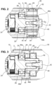
- Fig. 2 now shows the outbreak B from Fig. 1 in an enlarged view.
- the clutch unit 30 can be seen, which is mounted on the output shaft 26.
- the clutch unit 30 has a hub 40, which is mounted against the output shaft 26 by means of a screw 42.
- the output shaft 26 has a blind hole 44, which is provided with an internal thread.
- the hub 40 lies with a front end 46 against the roller bearing 28 when it is fixed axially on the output shaft 26 with the screw 42, as in the embodiment shown.
- the hub 40 has a substantially cylindrical basic shape which is provided with radial projections 48a, 48b.
- a coupling bushing 50 is provided which is formed in one piece.
- the coupling bushing 50 has an output section 52 which in this embodiment is connected at certain points in a frictionally engaged manner to the inner circumferential surface 12 of the roller body in order to transmit torque.
- the coupling bushing 50 has a plurality of radial lugs 54 which are in contact with the inner circumferential surface 12.
- the lugs 54 together define a diameter D1 that is slightly larger than the diameter D2, which is the inner diameter of the roller body 2.
- the individual lugs 54 are designed to be slightly springy so that they can be elastically deformed, in particular so that the diameter D1 is reduced.
- the coupling bushing 50 can be arranged axially in the interior 14 of the roller body 2, with the lugs 54 elastically exerting a radial force on the inner circumferential surface 12, so that a frictional connection between the coupling bushing 50 and the roller body 2 is achieved.
- the coupling bushing 50 further comprises a web 56 which extends radially at an axial end of the output section 52, but has a diameter which is smaller than the diameter D2.
- the web 56 is not used for torque transmission, but solely for positioning the coupling bushing 50.
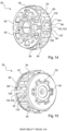
- FIG. 3 an embodiment of the invention is shown. Identical and similar elements are provided with the same reference numerals, and in this respect reference is made in full to the above description. Fig. 2 and 1 reference is made.
- Fig. 3 also exhibits outbreak B Fig. 1 , in which case a different coupling bushing 50 is used.
- the coupling bushing 50 sits on the hub 40, which in turn is constructed like the hub 40 according to the first example ( Fig. 2 ) is provided with radial projections 48c, 48d.
- the coupling bush 50 is in two parts and is mounted with reference to the Fig. 10 and 11 will be explained in more detail.
- the coupling bushing 50 has a radially outer part 60 and a radially inner part 62, wherein the radially inner part 62 is made of a flexible material, in particular a plastic or elastomer.
- the outer part 60 has the output section 52, which according to this exemplary embodiment is designed as an axially extending collar.
- the collar 64 of the output section 52 is made of a thin-walled sheet metal material, which in particular has a smaller thickness than the roller body 2. According to this exemplary embodiment, the thickness of the collar 64 is approximately half the thickness of the roller body 2, in particular 40%, 30% or less.
- the coupling bushing 50 is connected to the roller body 2 via a material connection.
- several welding points 66a, 66b are provided, which connect the collar 64 to the inner circumferential surface 12 of the roller body 2.
- the individual welding points 66a, 66b can be formed axially slightly offset from an axial front end of the collar 64, as shown in the case of welding point 66a, or directly at the axial end, as shown in the case of welding point 66b. In this way, manufacturing tolerances and manufacturing inaccuracies of the collar 64 and the roller body 2 can be compensated for.
- the collar 64 is made of a relatively thin sheet metal material and can therefore also be easily compressed radially.
- the coupling bushing 50 to be inserted, even if the collar 64 is slightly larger than the diameter of the roller body 2.
- the collar 64 is made of a relatively thin sheet material, it is not able to provide a sufficient force-fitting press connection between the coupling bushing 50 and the roller body 2. In order to transmit torque, the collar 64 is therefore materially connected to the roller body 2 at a plurality of individual welding points.
- a laser device is preferably positioned from the outside at the pipe end and the laser beam is directed to the desired Places inside the pipe are focused in order to selectively melt the components to be joined.
- Fig. 2 and the embodiment of the Fig. 3 can also be combined and only their structure initially in the Fig. 2 and 3 represent various alternatives. It is also preferred to additionally connect the individual lugs 54 to the inner circumferential surface 12 of the roller body 2 via welding points 66a, 66b in order to achieve an even more effective torque transmission.
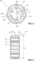
- Fig. 4 shows first a coupling bushing 50, as it is basically also shown in the example according to the Fig. 1 and 2 is installed.
- Fig. 5 shows the cross section AA from Fig. 4 , and in the following both figures will be discussed equally.
- the coupling bushing 50 has an output section 52 and a plurality of radial lugs 54 arranged thereon.
- a total of seven lugs 54 (in Fig. 4 only two are provided with reference numerals) evenly distributed around the circumference.
- the lugs 54 together define a diameter D1 (see Fig. 5 ), which is slightly larger than the diameter D2 of the roller body 2.
- the lugs 54 have a cross-section (cf. Fig. 4 ) have a spherical profile and have two essentially flat flanks 68a, 68b and a round tip 70. Due to this design, the noses 54 are somewhat elastic overall in that they can expand in the circumferential direction through radial compression. This makes it possible to compensate for tolerances and still produce a good frictional connection between the coupling bushing 50 and the roller body 2.
- the lugs 54 also have spherical insertion surfaces 72a, 72b, so that the coupling bushing 50 can easily be joined in the axial direction into the interior 14 of the roller body 2.
- the coupling bush 50 has a central recess 74, which is designed as a through-hole. By means of this recess 74, the coupling bush 50 can be pushed onto the hub 40 in the axial direction.
- the inner circumferential surface 76 of the central recess 74 has a contour which provides a positive Connection in the direction of rotation between the hub 40 and the coupling sleeve 50 is permitted.
- a plurality of projections 78 and recesses 80 are provided on the central recess 74 (in Fig. 4 only one of them is provided with a reference number), which are evenly distributed around the circumference of the central recess 74.
- axial recesses 82 are provided in the area of the projections 78 (cf. Fig. 6 ). These axial recesses 82 have a cross-section perpendicular to the axis of rotation of the coupling bush 50 (i.e. in the plane of the drawing according to Fig. 6 ) has a substantially trapezoidal shape. Its tip 83 corresponds substantially to the contour of the projection 78, so that a wall 84 which separates the axial recess 82 from the central recess 74 in the region of the projections 78 has a substantially constant wall thickness.
- the projections 78 have a concave contour 86 radially inwardly at the tips.
- the lateral flanks 88a, 88b of the projections 78 are essentially radially aligned. This results in the recesses 80 widening slightly radially outwards and opening into a concavely shaped base 90.
- the radial alignment of the lateral flanks 88a, 88b results in the radial projections 48a, 48b on the hub 40 coming into contact flush with the flanks 88a, 88b and a force from the projections 48a, 48b acting essentially perpendicularly on the flanks 88a, 88b.
- the axial recesses 82 lead on the one hand to a weight reduction, on the other hand they explicitly serve the slightly elastic design of the projections 78, which serves to cushion jolts and other load peaks.
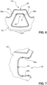
- the Fig. 8 and 9 illustrate a second embodiment, which is similar to the first example.
- the coupling bushing 50 is formed in two parts. It has a radially inner part 62 and a radially outer part 60, which forms the output section 52.
- the inner part 62 has a substantially cylindrical peripheral surface 92, on which the outer part 60 is applied in the form of a corrugated sheet metal strip.
- the corrugated sheet metal strip of the outer part 60 forms a plurality of lugs 54, which in this embodiment are then hollow and define a cavity 94 in the interior. This the elasticity of the lugs 54 is further developed and manufacturing tolerances can be compensated even more effectively.
- Fig. 9 shows a slightly modified embodiment in which not only trapezoidal recesses 82 are formed in the area of the projections 78, but also essentially rectangular axial recesses 96 in the area of the recesses 80. This leads to a further reduction in weight and also to a further elastic design of the coupling bushing 50.
- the hub 40 has an inner hub part 41, which is preferably made of a substantially rigid material, such as wear-resistant plastic such as polyamide.
- the inner hub part 41 has a central recess 43, via which the hub 40 can be connected to the corresponding section of the output shaft 26.
- the central recess 43 has a first section 43a with an internal polygon, and a stop ring 43b.
- the internal polygon cooperates with the corresponding external polygon of the output shaft 26 for torque transmission.
- the stop ring 43b is used for axial positioning.
- the hub 40 further comprises an outer part 45 which radially and circumferentially surrounds the inner part 41 and is preferably formed from a flexible material, such as in particular an elastomer material.
- the outer part 41 defines the projections 48a, 48b, 48c, 48d (in the Figures 10 and 11 not all projections are provided with a reference number).
- the projections 48a, 48b, 48c, 48d are each supported by a web 47a, 47b, 47d which is formed on the inner part 41 and extends radially therefrom.
- the webs 47a, 47b, 47d provide reinforcement for the projections 48a, 48b, 48c, 48d.
- the projections 48a, 48b, 48c, 48d each have a radial tongue 49a, 49b, 49d, which together define a collar having a diameter D 4 that is larger than the diameter D 3 of the projections 48a, 48b, 48c, 48d.
- the purpose of the tongues 49a, 49b, 49d is to prevent the hub 40 from "wandering out” during operation if it is not secured by a screw 42.
- the hub 40 is arranged with the section 43a on the output shaft 26.
- the coupling bush 50 is then pushed on and then lies with its drive facing end face to the tongues 49a, 49b, 49d.
- the drive and coupling bushing 50 are in turn axially fixed; the drive via the end cap 4 and the coupling bushing 50 via its connection to the roller body 2. This also axially fixes the hub 40 and prevents it from "wandering out", even though it has a loose bearing and is not clamped by a screw 42.
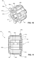
- the Fig. 12 and 13 illustrate another embodiment of the coupling bushing as shown in Fig. 3
- the coupling bushing is shown in the Fig. 12 and 13 is again in two parts and has an inner part 62 and an outer part 60.
- the inner part 62 is made of a plastic or elastomer material to compensate for a jolt or other load peaks.
- the output section 52 is here, as already mentioned with reference to Fig. 3 described, is designed as a collar 64 which extends away from a section 98 which encases the inner part 62. While the section 98 forms a radially outer shell for the flexible inner part 62, the collar 64 is made of a relatively thin sheet metal material which can be easily connected to the roller body 2 by means of spot welding.
- the axial extension of the collar 64 serves on the one hand to keep the collar 64 flexible in order to be able to both expand and contract radially in order to compensate for manufacturing tolerances. On the other hand, this also provides a spatial distance between the welding points and the inner part 62 in order to avoid heating of the flexible inner part 62. The use of laser spot welding further increases this effect.
- the inner part 62 has, according to the first embodiments, a central recess 74 which has an inner contour 76 which is approximately star-shaped. This contour 76 also has projections 78 and recesses 80 which are equally distributed around the circumference. The alternating recesses 80 and projections 78 serve to allow a positive force transmission and torque transmission from the hub 40 to the coupling bushing 50.
- FIGS. 14 and 15 show a further embodiment of the coupling bushing 50.
- this embodiment is similar to the second third embodiment ( Fig. 8 ) and the coupling bushing 50 is formed in two parts with a radially outer part 60, which defines the output section 52, and a radially inner part 62.
- the radially outer part 60 is in turn formed as a corrugated sheet metal strip which sits on a substantially cylindrical peripheral surface 92 of the radially inner part 62.
- the corrugated sheet metal strip has a radial gap 99 which is delimited by a first end section 104 and a second end section 105. This gap 99 is also present in the sheet metal strip of the third embodiment ( Fig. 8 ). It serves to adapt the sheet metal strip more easily to the diameter of the radially inner part 62.
- the radially inner part 62 has, as already seen from the first embodiment ( Fig. 5 ), has a web 56 which has a larger diameter than the peripheral surface 92 and thus serves for the axial positioning of the radially outer part 60.
- an anti-twist device 100 is provided.
- the anti-twist device 100 has a stop 102 against which one of the first and second end sections 104, 105 can strike.
- the stop 102 sits within the gap 99, but has a smaller circumferential extent, so that a certain rotation of the radially outer part 60 is permitted until the first or second end section 104, 105 comes into contact with the stop 102.
- Circumferential front sides 106, 107 (cf. Fig. 14 ) of the stop 102 are radially aligned so that they provide a flat contact surface for the end sections 104, 105. This provides a secure contact that can prevent the radially outer part 60 from coming loose and axially moving away from the web 56.
- the diameter or radial extent of the stop 102 is equal to or less than that of the web 56 to enable easy assembly.
- stop 102 instead of the stop 102, however, a purely material-locking anti-twisting device is also conceivable, for example by providing one or more welding points to connect the sheet metal strip to the peripheral surface 90.
- the hub 40 of the Fig. 10 The recesses 82 are in this embodiment ( Fig. 14, 15 ) are designed as blind hole-like recesses, so that the axial front side in Fig. 15 appears closed. This saves material (mass inertia/costs) and allows for almost constant wall thicknesses to be achieved, which is advantageous for cast/injection-molded parts.
Landscapes
- Engineering & Computer Science (AREA)
- General Engineering & Computer Science (AREA)
- Mechanical Engineering (AREA)
- Rolls And Other Rotary Bodies (AREA)
- Rollers For Roller Conveyors For Transfer (AREA)
Claims (13)
- Rouleau de convoyage (1) entraîné par moteur, destiné à des systèmes de convoyage pour convoyer des conteneurs, des palettes et analogues, pourvu- d'un corps de rouleau (2), dont la surface circonférentielle extérieure représente une surface de dépose pour des produits à convoyer,- d'une unité d'entraînement (18), qui est placée à l'intérieur de l'espace intérieur (14) du corps de rouleau (2),- d'une unité d'accouplement (30), conçue pour la transmission d'un couple de rotation de l'unité d'entraînement (18) sur une surface circonférentielle intérieure (12) de l'espace intérieur (14) du corps de rouleau (2), laquelle comporte un manchon d'accouplement (50), qui comporte une section d'entraînement, qui est en liaison avec l'unité d'entraînement (18) et qui comporte une section de sortie (52) extérieure périphérique,le manchon d'accouplement (50) étant en deux ou en plusieurs parties et comportant une partie (60) extérieure en direction radiale, laquelle définit la section de sortie (52) et une partie (62) intérieure en direction radiale, laquelle constitue une partie d'une liaison arbre-moyeu et est reliée avec un arbre de sortie (26) de l'entraînement,la partie (62) intérieure en direction radiale étant conçue en une matière souple, notamment en une matière élastomère,caractérisé en ce quele manchon d'accouplement (50) n'est relié que ponctuellement par friction avec la surface circonférentielle intérieure (12) du corps de rouleau (2), pour la transmission de couples de rotation.
- Rouleau de convoyage selon la revendication 1, la section de sortie (52) du manchon d'accouplement (50) comportant une pluralité d'ergots (54) radiaux qui sont prévus pour être en contact avec la surface circonférentielle intérieure (12) du corps de rouleau (2).
- Rouleau de convoyage selon la revendication 2, les ergots (54) radiaux définissant en commun un diamètre (D1) qui est supérieur au diamètre (D2) de la surface circonférentielle intérieure (12).
- Rouleau de convoyage selon la revendication 3, les ergots (54) étant conçus en étant souples et de préférence à intérieur creux.
- Rouleau de convoyage selon l'une quelconque des revendications précédentes, autour d'une circonférence de la section de sortie (52) étant prévus de 3 à 20, de préférence de 5 à 15, de manière particulièrement préférentielle de 7 à 10 points de liaison (54, 66a, 66b) séparés, sur lesquels le manchon d'accouplement (50) est relié ponctuellement avec la surface circonférentielle intérieure (12) du corps de rouleau (2).
- Rouleau de convoyage selon l'une quelconque des revendications précédentes, la partie (60) extérieure en direction radiale étant conçue sous la forme d'un ruban de tôle ondulé.
- Rouleau de convoyage selon la revendication 6, la partie (62) intérieure en direction radiale comportant une surface circonférentielle (92) sensiblement cylindrique, sur laquelle est posée la partie (60) extérieure.
- Rouleau de convoyage selon l'une quelconque des revendications précédentes, comportant un blocage anti-rotation (100), destiné à bloquer la partie (60) extérieure en direction radiale contre une rotation par rapport à la partie (62) intérieure en direction radiale, notamment un blocage anti-rotation par complémentarité de forme, le blocage anti-rotation (100) étant conçu de préférence sous la forme d'une butée (102), contre laquelle bute une section d'extrémité (104, 105) circonférentielle de la partie (60) extérieure en direction radiale.
- Rouleau de convoyage selon l'une quelconque des revendications précédentes, le manchon d'accouplement (50) étant logé de manière déplaçable en direction axiale, en rapport à l'unité d'entraînement (18).
- Rouleau de convoyage selon l'une quelconque des revendications précédentes, le manchon d'accouplement (50) comportant un évidement (74) central, dans lequel est inséré un arbre de sortie (26),l'évidement (74) central comportant des saillies (78) et des évidements (80) s'étendant réciproquement en direction radiale sur la circonférence,les saillies (78) étant aplaties de forme concave de préférence sur les pointes (86) intérieures en direction radiale et des flancs (88a, 88b) latéraux des saillies (78) radiales étant orientés de préférence sensiblement en direction radiale.
- Rouleau de convoyage selon la revendication 10, le manchon d'accouplement (50) comportant dans la zone des saillies (78) radiales des évidements (82) axiaux, les évidements (82) axiaux étant de préférence de forme sensiblement trapézoïdale dans leur section transversale.
- Rouleau de convoyage selon l'une quelconque des revendications précédentes, le manchon d'accouplement (50) comportant une collerette (64) s'étendant en direction axiale, sur laquelle est conçue la section de sortie (52).
- Rouleau de convoyage (1) entraîné par moteur, destiné à des systèmes de convoyage pour convoyer des conteneurs, des palettes et analogues, pourvu- d'un corps de rouleau (2), dont la surface circonférentielle extérieure représente une surface de dépose pour des produits à convoyer,- d'une unité d'entraînement (18), qui est placée à l'intérieur de l'espace intérieur (14) du corps de rouleau (2),- d'une unité d'accouplement (30), conçue pour la transmission d'un couple de rotation de l'unité d'entraînement (18) sur une surface circonférentielle intérieure (12) de l'espace intérieur (14) du corps de rouleau (2), laquelle comporte un manchon d'accouplement (50), qui comporte une section d'entraînement, qui est en liaison avec l'unité d'entraînement (18) et qui comporte une section de sortie (52) extérieure périphérique,le manchon d'accouplement (50) n'étant relié que ponctuellement par conjugaison de matières pour la transmission de couples de rotation avec la surface circonférentielle intérieure (12) du corps de rouleau (2),le manchon d'accouplement (50) étant en deux ou en plusieurs parties et comportant une partie (60) extérieure en direction radiale, laquelle définit la section de sortie (52) et une partie (62) intérieure en direction radiale, laquelle constitue une partie d'une liaison arbre-moyeu et est reliée avec un arbre de sortie (26) de l'entraînement,le manchon d'accouplement (50) comportant une collerette (64) s'étendant en direction axiale, sur laquelle est conçue la section de sortie (52,caractérisé en ce quela collerette (64) s'étend en s'éloignant en direction axiale d'une section (98) enveloppant la partie (62) intérieure et n'est reliée que ponctuellement par conjugaison de matières pour la transmission de couples de rotation avec la surface circonférentielle intérieure (12) du corps de rouleau (2).
Applications Claiming Priority (2)
| Application Number | Priority Date | Filing Date | Title |
|---|---|---|---|
| DE102016124689.1A DE102016124689B4 (de) | 2016-12-16 | 2016-12-16 | Förderrolle mit reib- und/oder stoffschlüssiger Kupplungsbuchse |
| PCT/EP2017/083025 WO2018109165A1 (fr) | 2016-12-16 | 2017-12-15 | Rouleau de manutention doté d'une douille d'accouplement entraînée par friction et/ou par continuité de matière |
Publications (2)
| Publication Number | Publication Date |
|---|---|
| EP3554968A1 EP3554968A1 (fr) | 2019-10-23 |
| EP3554968B1 true EP3554968B1 (fr) | 2024-11-27 |
Family
ID=60788602
Family Applications (1)
| Application Number | Title | Priority Date | Filing Date |
|---|---|---|---|
| EP17818536.9A Active EP3554968B1 (fr) | 2016-12-16 | 2017-12-15 | Rouleau de manutention doté d'une douille d'accouplement entraînée par friction et/ou par continuité de matière |
Country Status (9)
| Country | Link |
|---|---|
| US (1) | US10926959B2 (fr) |
| EP (1) | EP3554968B1 (fr) |
| JP (1) | JP6923651B2 (fr) |
| KR (1) | KR20190095390A (fr) |
| CN (1) | CN110214118B (fr) |
| BR (1) | BR112019011971A2 (fr) |
| CA (1) | CA3046111C (fr) |
| DE (2) | DE102016124689B4 (fr) |
| WO (1) | WO2018109165A1 (fr) |
Families Citing this family (15)
| Publication number | Priority date | Publication date | Assignee | Title |
|---|---|---|---|---|
| DE102017121486B4 (de) | 2017-09-15 | 2019-05-23 | Interroll Holding Ag | Motorbetriebene Förderrolle mit in das Trommelrohr eingepresster Kühlhülse |
| DE102018133478A1 (de) | 2018-12-21 | 2020-06-25 | Interroll Holding Ag | Motorbetriebene Förderrolle mit integrierter Steuerung |
| EP3715285B1 (fr) * | 2019-03-08 | 2024-05-01 | Intelligrated Headquarters LLC | Rouleau de convoyeur motorisé comportant un ensemble d'entraînement |
| US12145805B2 (en) | 2019-06-04 | 2024-11-19 | Nidec Motor Corporation | Integrated conveyor motor |
| US11014756B2 (en) | 2019-06-04 | 2021-05-25 | Nidec Motor Corporation | Integrated conveyor motor |
| JP2022098345A (ja) * | 2020-12-21 | 2022-07-01 | ロベルト・ボッシュ・ゲゼルシャフト・ミト・ベシュレンクテル・ハフツング | ブレーキ液圧制御装置およびその製造方法 |
| EP4291514A1 (fr) * | 2021-02-12 | 2023-12-20 | Interroll Holding AG | Rouleau de transport |
| WO2022182999A1 (fr) | 2021-02-26 | 2022-09-01 | Nidec Motor Corporation | Convoyeur double pour véhicule guidé autonome |
| DE102021112177A1 (de) | 2021-05-10 | 2022-11-10 | Interroll Holding Ag | Förderrolle |
| US11603269B2 (en) * | 2021-08-05 | 2023-03-14 | Dorner Mfg. Corp. | Mounting assembly for gearmotor of a conveyor assembly |
| DE102021121235A1 (de) | 2021-08-16 | 2023-02-16 | Vecoplan Ag | Zerkleinerungsanordnung mit Einzugswalze |
| EP4493492A1 (fr) | 2022-03-16 | 2025-01-22 | Interroll Holding AG | Rouleau de frein, transporteur à rouleaux et procédé d'installation d'un transporteur à rouleaux |
| CN115818152A (zh) * | 2022-11-25 | 2023-03-21 | 浙江德马工业设备有限公司 | 一种电动辊筒 |
| CN116054478A (zh) * | 2023-02-15 | 2023-05-02 | 深圳市兆威机电股份有限公司 | 张紧结构及滚筒电机 |
| WO2025065537A1 (fr) * | 2023-09-28 | 2025-04-03 | 德昌电机(江门)有限公司 | Rouleau à entraînement direct et dispositif transporteur du type rouleau |
Citations (3)
| Publication number | Priority date | Publication date | Assignee | Title |
|---|---|---|---|---|
| DE8212286U1 (de) * | 1982-04-29 | 1984-09-20 | Karl Stumpf Kg, 4282 Velen | Rollenbahnrolle |
| US6286659B1 (en) * | 1996-06-11 | 2001-09-11 | Gebo Conveyors, Consultants & Systems, Inc. | Motorized conveyor pulley |
| DE20319969U1 (de) * | 2003-12-23 | 2004-03-11 | Siemens Ag | Rotationsträger mit elastischer Verbindungseinrichtung zum Einbau elektrischer Maschinen in Rohre |
Family Cites Families (19)
| Publication number | Priority date | Publication date | Assignee | Title |
|---|---|---|---|---|
| JPS5314678B2 (fr) | 1973-10-01 | 1978-05-19 | ||
| JPH0678324A (ja) | 1992-08-25 | 1994-03-18 | Sony Corp | デジタルカラー映像信号の振幅制限方法及び振幅制限装置 |
| JPH0678324U (ja) * | 1993-04-14 | 1994-11-04 | 伊東電機株式会社 | モータ内蔵ローラ |
| US5442248A (en) * | 1994-04-11 | 1995-08-15 | Interroll Holding, A.G. | Motorized pulley with integral electrical connector |
| US7566102B2 (en) * | 2000-09-21 | 2009-07-28 | Innowheel Pty Ltd. | Multiple roller wheel |
| JP3673923B2 (ja) | 2002-12-09 | 2005-07-20 | 伊東電機株式会社 | ローラ装置、並びに、ローラ装置の製造方法 |
| DE10336304B4 (de) | 2003-07-31 | 2020-08-27 | Interroll Holding Ag | Motorbetriebene Förderrolle, Steuervorrichtung für eine motorbetriebene Förderrolle, Rollenförderanlage und Steuerverfahren für eine Rollenförderanlage |
| JP2006220172A (ja) | 2005-02-08 | 2006-08-24 | Kurashiki Kako Co Ltd | アルミ金具複合防振体及びその製造方法 |
| JP4992006B2 (ja) | 2007-07-11 | 2012-08-08 | 伊東電機株式会社 | モータ内蔵ローラ |
| WO2009139068A1 (fr) | 2008-05-16 | 2009-11-19 | 株式会社協和製作所 | Rouleau de transporteur à rouleaux à moteur intégré et dispositif transporteur à rouleaux utilisant ce dernier |
| JP2010001900A (ja) | 2008-06-18 | 2010-01-07 | Bridgestone Corp | 防振装置 |
| EP2466730A1 (fr) | 2010-12-20 | 2012-06-20 | Cyoris Ag | Entraînement de galets sans engrenage |
| DE202012005380U1 (de) | 2012-06-01 | 2013-09-03 | Interroll-Holding Ag | Motorbetriebene Förderrolle für Förderanlagen zum Fördern von Behältern, Paletten und dergleichen |
| DE202013002290U1 (de) | 2013-03-11 | 2014-06-12 | Interroll-Holding Ag | Förderrolle mit Versteifungselement |
| JP6432078B2 (ja) | 2014-05-07 | 2018-12-05 | 伊東電機株式会社 | モータ内蔵ローラ、動力伝達部材及びモータ内蔵ローラの製造方法 |
| EP3031758A1 (fr) | 2014-12-10 | 2016-06-15 | Reifenhäuser GmbH & Co. KG Maschinenfabrik | Arbre d'enroulement et procédé d'insertion d'un arbre d'enroulement dans un dispositif d'enroulement |
| DE102014018769B3 (de) * | 2014-12-16 | 2016-03-03 | Interroll Holding Ag | Rolle mit Innenbaugruppe |
| JP6610922B2 (ja) | 2015-04-24 | 2019-11-27 | 伊東電機株式会社 | モータ内蔵ローラ、及び動力伝達部材 |
| DE102016125136B4 (de) * | 2016-12-21 | 2020-09-10 | Interroll Holding Ag | Förderrolle mit konischem Aufschiebling |
-
2016
- 2016-12-16 DE DE102016124689.1A patent/DE102016124689B4/de active Active
-
2017
- 2017-12-15 US US16/469,195 patent/US10926959B2/en active Active
- 2017-12-15 KR KR1020197020471A patent/KR20190095390A/ko not_active Ceased
- 2017-12-15 EP EP17818536.9A patent/EP3554968B1/fr active Active
- 2017-12-15 WO PCT/EP2017/083025 patent/WO2018109165A1/fr not_active Ceased
- 2017-12-15 DE DE202017006722.6U patent/DE202017006722U1/de active Active
- 2017-12-15 BR BR112019011971-0A patent/BR112019011971A2/pt not_active Application Discontinuation
- 2017-12-15 CN CN201780084466.6A patent/CN110214118B/zh active Active
- 2017-12-15 CA CA3046111A patent/CA3046111C/fr active Active
- 2017-12-15 JP JP2019532003A patent/JP6923651B2/ja active Active
Patent Citations (3)
| Publication number | Priority date | Publication date | Assignee | Title |
|---|---|---|---|---|
| DE8212286U1 (de) * | 1982-04-29 | 1984-09-20 | Karl Stumpf Kg, 4282 Velen | Rollenbahnrolle |
| US6286659B1 (en) * | 1996-06-11 | 2001-09-11 | Gebo Conveyors, Consultants & Systems, Inc. | Motorized conveyor pulley |
| DE20319969U1 (de) * | 2003-12-23 | 2004-03-11 | Siemens Ag | Rotationsträger mit elastischer Verbindungseinrichtung zum Einbau elektrischer Maschinen in Rohre |
Also Published As
| Publication number | Publication date |
|---|---|
| CA3046111C (fr) | 2022-04-05 |
| CN110214118A (zh) | 2019-09-06 |
| DE102016124689A1 (de) | 2018-06-21 |
| JP6923651B2 (ja) | 2021-08-25 |
| JP2020502007A (ja) | 2020-01-23 |
| DE202017006722U1 (de) | 2018-03-02 |
| EP3554968A1 (fr) | 2019-10-23 |
| DE102016124689B4 (de) | 2021-07-29 |
| BR112019011971A2 (pt) | 2019-11-05 |
| CN110214118B (zh) | 2021-09-07 |
| US10926959B2 (en) | 2021-02-23 |
| KR20190095390A (ko) | 2019-08-14 |
| WO2018109165A1 (fr) | 2018-06-21 |
| US20200102151A1 (en) | 2020-04-02 |
| CA3046111A1 (fr) | 2018-06-21 |
Similar Documents
| Publication | Publication Date | Title |
|---|---|---|
| EP3554968B1 (fr) | Rouleau de manutention doté d'une douille d'accouplement entraînée par friction et/ou par continuité de matière | |
| EP3853490B1 (fr) | Dispositif d'arbre | |
| WO2008122277A2 (fr) | Ensemble roulement de roue | |
| EP2778100B1 (fr) | Rouleau de manutention avec raidisseur | |
| DE3001998C2 (de) | Befestigungshülse für Maschinenteile | |
| DE102012007329A1 (de) | Welle-Nabe-Verbindung | |
| EP2897887B1 (fr) | Rouleau de transport muni d'un élément de raccordement | |
| DE102007027934B4 (de) | Welle-Nabe-Baugruppe mit Spreizelement | |
| DE69703347T2 (de) | Übertragungsgelenkkreuz und entsprechendes übertragungsgelenk | |
| EP3190302A1 (fr) | Agencement d'etancheite pour un equilibrage des longueurs d'un arbre de transmission et arbre de transmission | |
| EP2078872B1 (fr) | Agencement de palier | |
| DE102007016742A1 (de) | Gelenklager, insbesondere an einem Drehgelenk zwischen einem Vorderwagen und Hinterwagen eines Gelenkbusses | |
| DE2910979C2 (de) | Kupplungsanordnung | |
| WO2008155041A1 (fr) | Rouleau de transport monté au moyen de cuvettes de palier | |
| DE102017121653A1 (de) | Bundlager mit parallel zueinander gerichteten Verklinkungen | |
| DE19510761B4 (de) | Anlaufscheibe für Gelenkkreuzbüchsen | |
| DE102005026499B4 (de) | Lageranordnung | |
| DE102021125484B4 (de) | Schubgestänge für einen Linearaktuator und Linearaktuator mit einem Schubgestänge | |
| DE102022209234A1 (de) | Lenkantrieb für ein Flurförderzeug, lenkbare Antriebseinheit für ein Flurförderzeug, Flurförderzeug und Verfahren zur Montage eines Lenkantriebs für ein Flurförderzeug | |
| EP1332082B1 (fr) | Systeme de colonne de direction et son procede de production | |
| WO2018192600A1 (fr) | Mécanisme fileté à roulement | |
| DE112013006601B4 (de) | Kugelgleichlaufverschiebegelenk und Anordnung mit Kugelgleichlaufverschiebegelenk | |
| DE102009055657A1 (de) | Radlagereinheit mit funktionskombiniertem Wälznietbund | |
| DE102020208514A1 (de) | Aktuator einer steer-by-wire-Lenkvorrichtung eines Kraftfahrzeuges sowie Verfahren zur Montage eines Aktuators einer steer-by-wire-Lenkvorrichtung | |
| EP2565480A1 (fr) | Elément mécanique de couplage ou d'embrayage |
Legal Events
| Date | Code | Title | Description |
|---|---|---|---|
| STAA | Information on the status of an ep patent application or granted ep patent |
Free format text: STATUS: UNKNOWN |
|
| STAA | Information on the status of an ep patent application or granted ep patent |
Free format text: STATUS: THE INTERNATIONAL PUBLICATION HAS BEEN MADE |
|
| PUAI | Public reference made under article 153(3) epc to a published international application that has entered the european phase |
Free format text: ORIGINAL CODE: 0009012 |
|
| STAA | Information on the status of an ep patent application or granted ep patent |
Free format text: STATUS: REQUEST FOR EXAMINATION WAS MADE |
|
| 17P | Request for examination filed |
Effective date: 20190716 |
|
| AK | Designated contracting states |
Kind code of ref document: A1 Designated state(s): AL AT BE BG CH CY CZ DE DK EE ES FI FR GB GR HR HU IE IS IT LI LT LU LV MC MK MT NL NO PL PT RO RS SE SI SK SM TR |
|
| AX | Request for extension of the european patent |
Extension state: BA ME |
|
| DAV | Request for validation of the european patent (deleted) | ||
| DAX | Request for extension of the european patent (deleted) | ||
| STAA | Information on the status of an ep patent application or granted ep patent |
Free format text: STATUS: EXAMINATION IS IN PROGRESS |
|
| 17Q | First examination report despatched |
Effective date: 20220314 |
|
| GRAP | Despatch of communication of intention to grant a patent |
Free format text: ORIGINAL CODE: EPIDOSNIGR1 |
|
| STAA | Information on the status of an ep patent application or granted ep patent |
Free format text: STATUS: GRANT OF PATENT IS INTENDED |
|
| RIC1 | Information provided on ipc code assigned before grant |
Ipc: F16D 1/10 20060101ALN20240704BHEP Ipc: B65G 23/08 20060101AFI20240704BHEP |
|
| RAP3 | Party data changed (applicant data changed or rights of an application transferred) |
Owner name: INTERROLL HOLDING AG |
|
| INTG | Intention to grant announced |
Effective date: 20240724 |
|
| RAP3 | Party data changed (applicant data changed or rights of an application transferred) |
Owner name: INTERROLL HOLDING AG |
|
| GRAS | Grant fee paid |
Free format text: ORIGINAL CODE: EPIDOSNIGR3 |
|
| GRAA | (expected) grant |
Free format text: ORIGINAL CODE: 0009210 |
|
| STAA | Information on the status of an ep patent application or granted ep patent |
Free format text: STATUS: THE PATENT HAS BEEN GRANTED |
|
| AK | Designated contracting states |
Kind code of ref document: B1 Designated state(s): AL AT BE BG CH CY CZ DE DK EE ES FI FR GB GR HR HU IE IS IT LI LT LU LV MC MK MT NL NO PL PT RO RS SE SI SK SM TR |
|
| REG | Reference to a national code |
Ref country code: GB Ref legal event code: FG4D Free format text: NOT ENGLISH |
|
| REG | Reference to a national code |
Ref country code: CH Ref legal event code: EP |
|
| REG | Reference to a national code |
Ref country code: IE Ref legal event code: FG4D Free format text: LANGUAGE OF EP DOCUMENT: GERMAN |
|
| REG | Reference to a national code |
Ref country code: DE Ref legal event code: R096 Ref document number: 502017016582 Country of ref document: DE |
|
| REG | Reference to a national code |
Ref country code: LT Ref legal event code: MG9D |
|
| REG | Reference to a national code |
Ref country code: NL Ref legal event code: MP Effective date: 20241127 |
|
| PG25 | Lapsed in a contracting state [announced via postgrant information from national office to epo] |
Ref country code: IS Free format text: LAPSE BECAUSE OF FAILURE TO SUBMIT A TRANSLATION OF THE DESCRIPTION OR TO PAY THE FEE WITHIN THE PRESCRIBED TIME-LIMIT Effective date: 20250327 Ref country code: PT Free format text: LAPSE BECAUSE OF FAILURE TO SUBMIT A TRANSLATION OF THE DESCRIPTION OR TO PAY THE FEE WITHIN THE PRESCRIBED TIME-LIMIT Effective date: 20250327 Ref country code: HR Free format text: LAPSE BECAUSE OF FAILURE TO SUBMIT A TRANSLATION OF THE DESCRIPTION OR TO PAY THE FEE WITHIN THE PRESCRIBED TIME-LIMIT Effective date: 20241127 |
|
| PG25 | Lapsed in a contracting state [announced via postgrant information from national office to epo] |
Ref country code: FI Free format text: LAPSE BECAUSE OF FAILURE TO SUBMIT A TRANSLATION OF THE DESCRIPTION OR TO PAY THE FEE WITHIN THE PRESCRIBED TIME-LIMIT Effective date: 20241127 Ref country code: NL Free format text: LAPSE BECAUSE OF FAILURE TO SUBMIT A TRANSLATION OF THE DESCRIPTION OR TO PAY THE FEE WITHIN THE PRESCRIBED TIME-LIMIT Effective date: 20241127 |
|
| PG25 | Lapsed in a contracting state [announced via postgrant information from national office to epo] |
Ref country code: BG Free format text: LAPSE BECAUSE OF FAILURE TO SUBMIT A TRANSLATION OF THE DESCRIPTION OR TO PAY THE FEE WITHIN THE PRESCRIBED TIME-LIMIT Effective date: 20241127 |
|
| PG25 | Lapsed in a contracting state [announced via postgrant information from national office to epo] |
Ref country code: ES Free format text: LAPSE BECAUSE OF FAILURE TO SUBMIT A TRANSLATION OF THE DESCRIPTION OR TO PAY THE FEE WITHIN THE PRESCRIBED TIME-LIMIT Effective date: 20241127 |
|
| PG25 | Lapsed in a contracting state [announced via postgrant information from national office to epo] |
Ref country code: NO Free format text: LAPSE BECAUSE OF FAILURE TO SUBMIT A TRANSLATION OF THE DESCRIPTION OR TO PAY THE FEE WITHIN THE PRESCRIBED TIME-LIMIT Effective date: 20250227 |
|
| PG25 | Lapsed in a contracting state [announced via postgrant information from national office to epo] |
Ref country code: LV Free format text: LAPSE BECAUSE OF FAILURE TO SUBMIT A TRANSLATION OF THE DESCRIPTION OR TO PAY THE FEE WITHIN THE PRESCRIBED TIME-LIMIT Effective date: 20241127 Ref country code: GR Free format text: LAPSE BECAUSE OF FAILURE TO SUBMIT A TRANSLATION OF THE DESCRIPTION OR TO PAY THE FEE WITHIN THE PRESCRIBED TIME-LIMIT Effective date: 20250228 |
|
| PG25 | Lapsed in a contracting state [announced via postgrant information from national office to epo] |
Ref country code: PL Free format text: LAPSE BECAUSE OF FAILURE TO SUBMIT A TRANSLATION OF THE DESCRIPTION OR TO PAY THE FEE WITHIN THE PRESCRIBED TIME-LIMIT Effective date: 20241127 |
|
| PG25 | Lapsed in a contracting state [announced via postgrant information from national office to epo] |
Ref country code: RS Free format text: LAPSE BECAUSE OF FAILURE TO SUBMIT A TRANSLATION OF THE DESCRIPTION OR TO PAY THE FEE WITHIN THE PRESCRIBED TIME-LIMIT Effective date: 20250227 |
|
| PG25 | Lapsed in a contracting state [announced via postgrant information from national office to epo] |
Ref country code: SM Free format text: LAPSE BECAUSE OF FAILURE TO SUBMIT A TRANSLATION OF THE DESCRIPTION OR TO PAY THE FEE WITHIN THE PRESCRIBED TIME-LIMIT Effective date: 20241127 |
|
| PG25 | Lapsed in a contracting state [announced via postgrant information from national office to epo] |
Ref country code: DK Free format text: LAPSE BECAUSE OF FAILURE TO SUBMIT A TRANSLATION OF THE DESCRIPTION OR TO PAY THE FEE WITHIN THE PRESCRIBED TIME-LIMIT Effective date: 20241127 |
|
| PG25 | Lapsed in a contracting state [announced via postgrant information from national office to epo] |
Ref country code: EE Free format text: LAPSE BECAUSE OF FAILURE TO SUBMIT A TRANSLATION OF THE DESCRIPTION OR TO PAY THE FEE WITHIN THE PRESCRIBED TIME-LIMIT Effective date: 20241127 |
|
| PG25 | Lapsed in a contracting state [announced via postgrant information from national office to epo] |
Ref country code: RO Free format text: LAPSE BECAUSE OF FAILURE TO SUBMIT A TRANSLATION OF THE DESCRIPTION OR TO PAY THE FEE WITHIN THE PRESCRIBED TIME-LIMIT Effective date: 20241127 |
|
| PG25 | Lapsed in a contracting state [announced via postgrant information from national office to epo] |
Ref country code: SK Free format text: LAPSE BECAUSE OF FAILURE TO SUBMIT A TRANSLATION OF THE DESCRIPTION OR TO PAY THE FEE WITHIN THE PRESCRIBED TIME-LIMIT Effective date: 20241127 |
|
| PG25 | Lapsed in a contracting state [announced via postgrant information from national office to epo] |
Ref country code: CZ Free format text: LAPSE BECAUSE OF FAILURE TO SUBMIT A TRANSLATION OF THE DESCRIPTION OR TO PAY THE FEE WITHIN THE PRESCRIBED TIME-LIMIT Effective date: 20241127 |
|
| PG25 | Lapsed in a contracting state [announced via postgrant information from national office to epo] |
Ref country code: IT Free format text: LAPSE BECAUSE OF FAILURE TO SUBMIT A TRANSLATION OF THE DESCRIPTION OR TO PAY THE FEE WITHIN THE PRESCRIBED TIME-LIMIT Effective date: 20241127 |
|
| REG | Reference to a national code |
Ref country code: CH Ref legal event code: PL |
|
| PG25 | Lapsed in a contracting state [announced via postgrant information from national office to epo] |
Ref country code: LU Free format text: LAPSE BECAUSE OF NON-PAYMENT OF DUE FEES Effective date: 20241215 |
|
| REG | Reference to a national code |
Ref country code: DE Ref legal event code: R097 Ref document number: 502017016582 Country of ref document: DE |
|
| PG25 | Lapsed in a contracting state [announced via postgrant information from national office to epo] |
Ref country code: SE Free format text: LAPSE BECAUSE OF FAILURE TO SUBMIT A TRANSLATION OF THE DESCRIPTION OR TO PAY THE FEE WITHIN THE PRESCRIBED TIME-LIMIT Effective date: 20241127 |
|
| PG25 | Lapsed in a contracting state [announced via postgrant information from national office to epo] |
Ref country code: MC Free format text: LAPSE BECAUSE OF FAILURE TO SUBMIT A TRANSLATION OF THE DESCRIPTION OR TO PAY THE FEE WITHIN THE PRESCRIBED TIME-LIMIT Effective date: 20241127 |
|
| PLBE | No opposition filed within time limit |
Free format text: ORIGINAL CODE: 0009261 |
|
| STAA | Information on the status of an ep patent application or granted ep patent |
Free format text: STATUS: NO OPPOSITION FILED WITHIN TIME LIMIT |
|
| REG | Reference to a national code |
Ref country code: BE Ref legal event code: MM Effective date: 20241231 |
|
| PG25 | Lapsed in a contracting state [announced via postgrant information from national office to epo] |
Ref country code: BE Free format text: LAPSE BECAUSE OF NON-PAYMENT OF DUE FEES Effective date: 20241231 |
|
| PG25 | Lapsed in a contracting state [announced via postgrant information from national office to epo] |
Ref country code: CH Free format text: LAPSE BECAUSE OF NON-PAYMENT OF DUE FEES Effective date: 20241231 |
|
| PG25 | Lapsed in a contracting state [announced via postgrant information from national office to epo] |
Ref country code: IE Free format text: LAPSE BECAUSE OF NON-PAYMENT OF DUE FEES Effective date: 20241215 |
|
| GBPC | Gb: european patent ceased through non-payment of renewal fee |
Effective date: 20250227 |
|
| 26N | No opposition filed |
Effective date: 20250828 |
|
| PG25 | Lapsed in a contracting state [announced via postgrant information from national office to epo] |
Ref country code: GB Free format text: LAPSE BECAUSE OF NON-PAYMENT OF DUE FEES Effective date: 20250227 |
|
| PGFP | Annual fee paid to national office [announced via postgrant information from national office to epo] |
Ref country code: FR Payment date: 20251217 Year of fee payment: 9 |
|
| REG | Reference to a national code |
Ref country code: AT Ref legal event code: MM01 Ref document number: 1745534 Country of ref document: AT Kind code of ref document: T Effective date: 20241215 |
|
| PGFP | Annual fee paid to national office [announced via postgrant information from national office to epo] |
Ref country code: DE Payment date: 20251222 Year of fee payment: 9 |
|
| PG25 | Lapsed in a contracting state [announced via postgrant information from national office to epo] |
Ref country code: AT Free format text: LAPSE BECAUSE OF NON-PAYMENT OF DUE FEES Effective date: 20241215 |