EP3557541A1 - Redresseur de bouteilles, dispositif automatique de recyclage et installation de tri - Google Patents
Redresseur de bouteilles, dispositif automatique de recyclage et installation de tri Download PDFInfo
- Publication number
- EP3557541A1 EP3557541A1 EP19163376.7A EP19163376A EP3557541A1 EP 3557541 A1 EP3557541 A1 EP 3557541A1 EP 19163376 A EP19163376 A EP 19163376A EP 3557541 A1 EP3557541 A1 EP 3557541A1
- Authority
- EP
- European Patent Office
- Prior art keywords
- empties
- transport element
- container
- bottle
- conveyor belt
- Prior art date
- Legal status (The legal status is an assumption and is not a legal conclusion. Google has not performed a legal analysis and makes no representation as to the accuracy of the status listed.)
- Granted
Links
Images

Classifications
-
- G—PHYSICS
- G07—CHECKING-DEVICES
- G07F—COIN-FREED OR LIKE APPARATUS
- G07F7/00—Mechanisms actuated by objects other than coins to free or to actuate vending, hiring, coin or paper currency dispensing or refunding apparatus
- G07F7/06—Mechanisms actuated by objects other than coins to free or to actuate vending, hiring, coin or paper currency dispensing or refunding apparatus by returnable containers, i.e. reverse vending systems in which a user is rewarded for returning a container that serves as a token of value, e.g. bottles
- G07F7/0609—Mechanisms actuated by objects other than coins to free or to actuate vending, hiring, coin or paper currency dispensing or refunding apparatus by returnable containers, i.e. reverse vending systems in which a user is rewarded for returning a container that serves as a token of value, e.g. bottles by fluid containers, e.g. bottles, cups, gas containers
Definitions
- the present invention relates to a bottle stand and a reverse vending machine and a sorting system with such a bottle stand.
- Automatic reverse vending machines or return systems serve to receive empty beverage packaging and to pay or credit a corresponding deposit to the user.
- Various types of beverage containers are intended for redemption, such as individual bottles, cans, or cups, etc.
- empty beverage containers are also referred to as empty containers.
- empties can be divided into different classes based on their characteristics, to which different deposit values are assigned.
- the characteristics are the external shape, the weight, any damage or residual filling present or a closure on the bottle.
- Automatic reverse vending machines are designed to determine the characteristics of a bottle introduced into the vending machine, to decide on the acceptance or rejection of the bottle and to issue a corresponding deposit.
- Assumed bottles can then be forwarded within the system and set up and collected for example by means of a bottle stand on a bottle table or in a corresponding intermediate storage area for further processing by the staff. Possibly In the course of bottle take-back, pre-sorting of the bottles may take place in order to be able to further process these as efficiently as possible according to their characteristics or properties.
- bottles are fed lying over a feed chute, then set up and optionally transported further, see for example the publication DE 100 61 462 C2 ,
- the present invention has the object to find the most efficient solutions for the return and / or sorting process of empties containers.
- this object is achieved by a bottle display with the features of claim 1, by a reverse vending machine with the features of claim 14 and / or by a sorting system with the features of claim 15.
- the idea on which the present invention is based is to stabilize an empty packaging container which may be supplied via a feed chute and, due to the impulse thus obtained, by tumbling it to a transport element which subsequently transports the empty container.
- the particular advantage of the present invention is now to be seen in that the transport element on the one hand serves as an object or barrier for pressing the empties container, on the other hand, however, at the same time acts as a means of transport for the empties container.
- the bottle stand according to the invention can be made very compact and simple.
- the number of items to be installed can be kept low, which ultimately saves manufacturing, maintenance and installation costs.
- the system according to the invention is less error-prone than known systems of the prior art.
- the bottle displays according to the invention are particularly suitable for use in reverse vending machines and / or sorting systems or similar devices in which a very large number of empties containers as efficient as possible and error-proof record, transport and / or to sort is.
- the bottle stands according to the invention can serve not only for the installation, transport and sorting of bottles in the true sense here. Rather, general empties containers, such as cans, cups, barrels, containers, etc. can be processed, which can be disposable containers or reusable containers.
- the feed chute can be designed for the substantially vertical supply of the empties package.
- the empties containers can be moved on a conveyor belt in a lying manner on the feed chute, at which they then slide obliquely and / or vertically down or fall so that they impinge in an approximately upright and / or approximately vertical position in the feed region.
- the empties containers can be provided here obliquely and / or tumbling over the feed chute in the feed region, with the empties containers subsequently being brought into a vertically stabilized rest position via the stabilizer.
- the transport element may be formed with at least one empties compartment.
- the stabilizer may be designed to push the supplied empties container into the at least one empties compartment.
- the transport element can be designed to further transport the inserted empties container in the at least one empties compartment.
- the stabilizer pushes the empties container thus first in the empties compartment and there against the transport element, for example against a back wall of the empties compartment.
- the stabilizer may be configured to press the empties container for a predetermined period of time to the transport element, in which this is sufficiently stabilized in its rest position. Subsequently, the empties container is moved by the transport element on.
- the stabilizer may be formed as a horizontal, linearly movable pressing member.
- the pressing member may be configured to push the supplied empties container from the feed chute against the transport element and to stabilize such. Afterwards, the pressing part can be returned again before the empty container is moved over the transport element.
- the empties compartment can be dimensioned accordingly, so that the empties containers to be transported remain safe and stable in the empties compartment when they are transported by the transport element.
- the bottle stand can be designed for the transport of returnable bottles, wherein the empties compartment is dimensioned such that a standing upright in the empties compartment bottle can not tip over.
- the transport element can be designed as a rotational body to transport the empties container by means of self-rotation on.
- an empties container is thus supplied via the feed chute, pressed to the transport element and thereby stabilized and then moved by rotation of the transport element.
- the transport element can be designed as a turnstile with several empties compartments.
- the turnstile may have two, three, four, five, six or more empties compartments.
- the empties compartments may be arranged one behind the other in a circumferential direction around the turnstile, wherein the empties compartments may be formed to be open radially outwardly.
- the perimeter of the turnstile may be divided into identically designed and dimensioned empties compartments, e.g. four empties compartments, each occupying an angular range of about 90 °.
- the turnstile may have four identical rotary blades, which are oriented radially from a center of the turnstile to the outside in the form of a cross, with two rotary blades defining an empties compartment in the circumferential direction. Due to the provision of multiple empties compartments, it is possible, for example, several empties containers at the same time to pass through the bottle stand and the transport element.
- the transport element may be designed to rotate continuously and / or stepwise.
- the transport element may be designed to rotate around an angle range corresponding to the number of empties compartments, for example, in the case of four identical empties compartments, a stepwise rotation through 90 ° may be provided.
- the transport element can likewise be designed with a plurality of empties compartments which cover different angular ranges, eg a total of three compartments with two times 90 ° and once 180 °, etc., so that a rotation can accordingly take place in variable or different steps.
- the transport element can likewise rotate continuously about its axis, wherein the rotational speed can be chosen to be so small, for example, that the stabilizer can insert a container of empties into an empties compartment and stabilize there, without, for example, a pressing part of the stabilizer coming into conflict with the movement of the transport element.
- the pressing member may retract again before the transport element is significantly further rotated.
- the transport element may be formed with three empties compartments.
- the transport element may be designed to rotate incrementally by 120 °.
- the transport element may alternatively or additionally be designed to rotate continuously.
- the bottle display can be designed with different operating modes in which the transport element is operated differently, e.g. optionally rotated continuously or stepwise.
- a first conveyor belt for further transport of the empties container can further be provided.
- the transport element can be designed to transfer the calmed empties container to the first conveyor belt.
- the transport element can rotate as a rotational body over at least a portion of the first conveyor belt, which is stopped during the rotation of the transport element. As soon as the empties container is on the first conveyor belt, the rotation of the transport element can be stopped and in return the first conveyor belt is started, which then carries the empties container away.
- a second conveyor belt may be provided for further transport of the empties container.
- the transport element may be designed to, the calmed empties can be handed over either to the first conveyor belt or the second conveyor belt.
- the bottle stand and / or the reverse vending machine or the sorting system can be designed to determine predetermined characteristics of the empties container.
- the transport element can now be designed to transfer the empties container either to the first conveyor belt or the second conveyor belt depending on the feature.
- the bottle stand also fulfills a sorting function in addition to a stabilization and transport function.
- the reverse vending machine, the sorting system and / or the bottle stand can have a sensor device by means of which one or more features of the empty goods package can be detected.
- a feature may be the outer shape and weight of a bottle, any damage or residue left over, an existing bar or bar code, or a closure on the bottle.
- the sensor device may be connected to a control device, which is designed to evaluate the feature detected by the sensor device.
- the control device can further control the bottle stand and / or the transport element accordingly, so that after the evaluation of the feature, the transport element is caused to transfer the empty goods container to the first conveyor belt or the second conveyor belt.
- a reverse vending machine may have an acceptance area in which empties containers can be inserted via an insertion opening attached to the outside of a housing of the reverse vending machine.
- this insertion opening may be, for example, circular and the acceptance area as be formed hollow cylindrical area.
- the acceptance area can furthermore comprise a conveyor belt, which forwards an emptied container introduced into the acceptance area to a sensor device, by means of which one or more features of the empties container are detected.
- the reverse vending machine can now include a control device which is connected to the sensor device.
- the control device may be a central control device of the reverse vending machine.
- the control device can likewise be provided in the bottle stand, for example in the feed area of the bottle stand. Accordingly, the sensor device or the sensor can be provided in or at the feed region.
- the control device of the reverse vending machine or the bottle stand can now be designed to instruct the transport element accordingly to sort the empties container in accordance with its determined characteristics.
- the transport element can be designed to transfer the empties container to the first conveyor belt by self-rotation in a direction of rotation.
- the transport element can be designed to transfer the empties container to the second conveyor belt by self-rotation counter to the direction of rotation.
- a particularly compact and efficient bottle stand is thus created, which implements the stabilization, transport and sorting of empties containers with a minimum number of system components.
- the transport element serves as a stabilization object or stabilization barrier, as a means of transport and as a sorting aid.
- a control device for controlling the stabilizer can furthermore be provided.
- a presence sensor may be provided in the feed area.
- the control device may be coupled to the presence sensor.
- the control device can be designed to detect the presence of an added empties container in the feed region by means of the presence sensor.
- the control device may also be configured to cause the stabilizer to push the empty container against the transport element, when the presence of a supplied empties container has been determined.
- the presence sensor can be designed as an optical sensor and / or weight sensor or the like.
- the presence sensor may be formed as a laser barrier, which is arranged below the feed chute in the feed region.
- the presence sensor may comprise a weight sensor in the feed area, e.g. in and / or on a floor below the feed chute.
- the stabilizer may be formed with a compensating spring mechanism for providing a variable pressing force.
- a compensating spring mechanism for providing a variable pressing force.
- different container diameters can be compensated, so that the bottle stand can process, for example, bottles of different sizes or different diameters.
- the idea on which this embodiment is based consists of selectively transferring an emptied container fed via a feed chute by means of a transport element to one of at least two conveyor belts and subsequently transporting it further thereon.
- a (pre-) sorting of the empties containers is thus already possible within the bottle stand.
- the bottle stand and / or the reverse vending machine or the sorting system can be designed to determine predetermined characteristics of the empties container.
- the transport element can now be designed to transfer the empties container either to the first conveyor belt or the second conveyor belt depending on the feature.
- the bottle stand can therefore also fulfill a sorting function in addition to a set-up and transport function. Furthermore, it can be provided to pass empty containers regardless of their specific characteristics on one of the conveyor belts.
- each of the conveyor belts can lead to a separate (intermediate) storage area for the empty containers. If, for example, one of the storage areas is currently filled, all the following empty containers can be routed via an alternative conveyor belt to a storage area that is not yet fully utilized. It is also possible that the empties container in case of failure of one of the conveyor belts and / or failure of one of these subsequent conveyor belt components via an alternative Conveyor be redirected. The system is thus more comfortable, more versatile and less prone to error than known systems of the prior art.
- the transport element may be designed as a rotational body to pass the empties container by means of self-rotation.
- an empties container is thus supplied via the feed chute and then moved on by means of rotation of the transport element.
- the transport element may be designed to transfer the empties container to the first conveyor belt by self-rotation in a direction of rotation.
- the transport element can rotate as a rotational body over at least a portion of the first conveyor belt, which is stopped during the rotation of the transport element.
- the rotation of the transport element can be stopped and in return the first conveyor belt is started, which then carries the empties container away.
- the transport element may be designed to transfer the empties container to the second conveyor belt by self-rotation counter to the direction of rotation.
- a particularly compact and efficient bottle display is thus created, which implements the stabilization, transport and sorting of empties containers with a minimum number of system components.
- the transport element serves simultaneously as a means of transport and as a sorting aid and optionally also as a stabilization object or stabilization barrier.
- the transport element may be formed with at least one empties compartment for the transport of the empties container.
- the feed chute be arranged and designed such that the empties container in the empties compartment, so to speak slips into it itself and is transported there.
- a stabilizer or the like may be configured to push the supplied empties container into the at least one empties compartment.
- the stabilizer may be designed to push the supplied empty containers in the feed area against the transport element to bring the empties container in a static rest position.
- the transport element can be designed to further transport the inserted empties container in the at least one empties compartment.
- the stabilizer pushes the empties container thus first in the empties compartment and there against the transport element, for example against a rear wall of the empties compartment.
- the stabilizer may be configured to press the empties container for a predetermined period of time to the transport element, in which this is sufficiently stabilized in its rest position. Subsequently, the empties container is moved by the transport element on.
- the stabilizer may be formed as a horizontal, linearly movable pressing member. The pressing member may be configured to push the supplied empties container from the feed chute against the transport element and to stabilize such. Afterwards, the pressing part can be returned again, before the empty container is put over the Transport element is moved further.
- the empties compartment can be dimensioned accordingly, so that the empties containers to be transported remain safe and stable in the empties compartment when they are transported by the transport element.
- the bottle stand can be designed for the transport of returnable bottles, wherein the empties compartment is dimensioned such that a standing upright in the empties compartment bottle can not tip over.
- the transport element may be formed as a turnstile with a plurality of empties compartments.
- the turnstile may have two, three, four, five, six or more empties compartments.
- the empties compartments may be arranged one behind the other in a circumferential direction around the turnstile, wherein the empties compartments may be formed to be open radially outwardly.
- the perimeter of the turnstile may be divided into identically designed and dimensioned empties compartments, e.g. four empties compartments, each occupying an angular range of about 90 °.
- the turnstile may have four identical rotary blades, which are oriented radially from a center of the turnstile to the outside in the form of a cross, with two rotary blades defining an empties compartment in the circumferential direction. Due to the provision of multiple empties compartments, it is possible, for example, several empties containers at the same time to pass through the bottle stand and the transport element.
- the transport element may be designed to rotate continuously and / or stepwise.
- the transport element may be designed to rotate an angular range corresponding to the number of empties compartments, For example, in the case of four identical empties compartments, a stepwise rotation by 90 ° may be provided.
- the transport element can also be designed with a plurality of empties compartments which cover different angular ranges, for example a total of three compartments with two times 90 ° and once 180 ° etc., so that a rotation can accordingly take place in variable or different steps.
- the transport element can also rotate continuously about its axis, wherein the rotational speed can be selected, for example, so low that an empties container can be introduced into an empties compartment, without this being in conflict with the movement of the transport element.
- the empties container can be inserted via a pressing member or a stabilizer in an empties compartment and stabilized there, with the pressing member retracts again before the transport element is significantly further rotated.
- the transport element may be formed with three empties compartments.
- the transport element may be designed to rotate incrementally by 120 °.
- the transport element may alternatively or additionally be designed to rotate continuously.
- the bottle display can be designed with different operating modes in which the transport element is operated differently, e.g. optionally rotated continuously or stepwise.
- the transport element may be configured to selectively deliver the empties container to the first conveyor belt or the second conveyor belt on the basis of identified empties characteristics of the empties container to hand over.
- the reverse vending machine, the sorting system and / or the bottle stand can have a sensor device, by which one or more empties characteristics of the empties container can be detected.
- an emptying feature may be the outer shape and weight of a bottle, any damage or residue left over, an existing bar or bar code, or a closure on the bottle.
- the sensor device may be connected to a control device, which is designed to evaluate the emptying feature detected by the sensor device.
- the control device can further control the bottle stand and / or the transport element accordingly, so that the transport element is caused after the evaluation of the emptying feature to pass the empties container to the first conveyor belt or the second conveyor belt.
- a reverse vending machine may have an acceptance area in which empties containers can be inserted via an insertion opening attached to the outside of a housing of the reverse vending machine.
- this insertion opening may be, for example, circular and the acceptance area may be formed as a hollow-cylindrical area.
- the acceptance area can furthermore comprise a conveyor belt which forwards an emptied container introduced into the acceptance area to a sensor device by which one or more empties characteristics of the empties container are detected.
- the reverse vending machine can now include a control device which is connected to the sensor device.
- the control device may be a central control device of the reverse vending machine.
- control device may be provided in the bottle stand be, for example in the feed area of the bottle stand. Accordingly, the sensor device or the sensor can be provided in or at the feed region.
- the control device of the reverse vending machine or the bottle stand can now be designed to instruct the transport element accordingly to sort the empties container according to its identified empties characteristics.
- a control device for controlling the transport element can furthermore be provided.
- the control device can be designed to determine the empties characteristics of the empties container and, based on this, to cause the transport element to transfer the empties container to the first conveyor belt or the second conveyor belt.
- the control device may receive or request otherwise identified empties characteristics of the empties package, e.g. by means of communication with a central control device of a reverse vending machine and / or a sorting system, wherein the empties features, for example, in an acceptance area of the reverse vending machine and / or the sorting system may already have been detected. Based on these empties features, the control device can now cause a corresponding sorting of the empties container on a specific conveyor belt.
- the control device may be coupled to sensors of the bottle stand, which in turn are designed to detect the empties characteristics of the empties container and forward them to the control device.
- control device may be coupled to a presence sensor in the feed region.
- the control device may be configured to Detecting the presence of a supplied empties container in the feed region by means of the presence sensor and, based on this, to cause the transport element to transfer the empties container to the first conveyor belt or the second conveyor belt.
- the presence sensor may be formed as an optical sensor and / or weight sensor or the like.
- the presence sensor may be formed as a laser barrier, which is arranged below the feed chute in the feed region.
- the presence sensor may comprise a weight sensor in the feed area, e.g. in and / or on a floor below the feed chute.
- the presence sensor may be configured to detect the empties characteristics of the empties container.
- the occupancy sensor may be designed to detect empties characteristics on the basis of identifiers attached to the empties container and / or on the basis of external features of the empties container, such as its weight, its external shape and / or its size or the like.
- the presence sensor may be formed, for example, as an optical sensor and / or as a weight sensor.
- the feed chute may be designed for the substantially vertical feed of the empties package.
- the empties can be moved via a conveyor belt in a lying manner on the feed chute, at which they then slid and / or vertically down or fall, so that they are in an approximately upright and / or approximately vertical position in the feed area.
- the empties containers can be provided here obliquely and / or tumbling over the feed chute in the feed region, with the empties containers subsequently being brought into a vertically stabilized rest position via a stabilizer or the like.
- the feed chute, the feed area and / or the transport element can be configured accordingly, so that a supplementary stabilization is not necessary, for example because the empties container is brought directly into an empties compartment of the transport element, wherein tumbling is prevented due to the walls of the empties compartment.
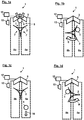
- Figure 1a-d show schematic plan views of a bottle display 1 according to one embodiment during the transport of a container Empties 4th
- the bottle display 1 shown is a machine that allows the installation, transportation and sorting of empties 4 such as bottles and the like.
- the empties 4 can be processed in different shapes, sizes and materials.
- the basic principle of the bottle stand is to supply the empty containers 4 via a feed chute 3 and transfer them to a transport element 2, which sorts them onto different conveyor belts 8a, 8b, where they are subsequently transported further.
- downstream machines for example, can be charged with the transported empties containers 4 and / or stored temporarily, eg on a collection table (cf. 3 and 4 ).
- the exact procedure of the transport is described below with reference to Fig. 1a-d explained.
- the bottle stand 1 comprises a transport element 2 and a feed chute 3, via which empties 4, eg bottles, are fed into a feed area 5 (indicated by arrows on the feed chute 3 in FIG Fig. 1a ).
- the empty containers 4 can be moved on a conveyor belt (not shown) or the like in a lying manner on the feed chute 3, at which they then slid or fall down or vertically, so that they are in a more or less upright or oblique position impinge in the feed area 5.
- the transport element 2 of the bottle maker 1 is designed to transfer the supplied empty container 4 optionally to the first conveyor belt 8a or the second conveyor belt 8b.
- the transport element 2 is formed as a turnstile, which the empties container 4 by means of self-rotation passes.
- the turnstile has three identically designed empties compartments 7, each occupying an angular range of 120 °.
- the empty container 4 is transferred to the first conveyor belt 8a by self-rotation in a direction of rotation 9 and to the second conveyor belt 8b by self-rotation counter to the direction of rotation 9.
- the empties container 4 is carried within the empties compartment 7 (see. Fig. 1b ).
- the transport element 2 is positioned on or on a first conveyor belt 8a in such a way that the empties container 4 is moved onto the conveyor belt 8a due to the rotation of the transport element 2 and can be carried by it in a conveying direction 16 (cf. Fig. 1c ). Due to the symmetrical design of the transport element 2, an empties compartment 7 is again aligned in the direction of the feed chute 3 after a rotation of 120 °, so that a further empties container 4 can be supplied. In principle, this can already happen during the rotation of the transport element 2.
- the empties container 4 can optionally also be transferred to the second conveyor belt 8b instead of the first conveyor belt 8a.
- the transport element 2 can rotate by self-rotation in a counter-rotation direction 9 'in the counterclockwise direction (cf. Fig. 1d ).
- the second conveyor belt 8b can now move the empties container 4 in a conveying direction 16 similar to the first conveyor belt 8a, wherein the conveying direction 16 can be identical to the conveying direction 16 of the first conveyor belt 8a, as shown in FIG.
- the two conveyor belts 8a, 8b run or are oriented in different directions.
- more than two conveyor belts are possible, For example, three, four or more conveyor belts, the expert will train the transport element in these cases accordingly, so that empty containers can be optionally transferred to the conveyor belts.
- the transport element 2 is configured to selectively transfer the empties container 4 to the first conveyor belt 8a or the second conveyor belt 8b on the basis of detected empties characteristics of the empty goods container 4.
- the bottle stand 1 a control device 12 for controlling the transport element 2, which identifies the empties characteristics of the empties 4 and based on the transport element 2 causes the empties 4 to pass to the first conveyor belt 8a or the second conveyor belt 8b.
- the control device 12 is communicatively connected to a presence sensor 13 in the feed area 5.
- the presence sensor 13 is designed to detect the presence of a supplied empties container 4 in the feed region 5.
- the presence sensor 13 may be used, for example, as an optical sensor, e.g.
- the presence sensor 13 detects this and transmits this information to the control device 12, which in turn initiates a rotation of the transport element 2 based thereon.
- the presence sensor 13 and / or another sensor (not shown) in the feed region 5 may be designed to detect one or more empties characteristics of the empties container 4.
- an empties feature the be external shape and the weight of the empties 4, any existing damage or residual filling, an existing bar or bar code or a closure located on the empties container etc.
- the control device 12 may be configured to evaluate the detected by the sensor empties feature and building on it To rotate the transport element 2 either in the direction of rotation 9 or alternatively in the counter-rotation direction 9 'to further transport the empties container 4 either on the first conveyor belt 8a or the second conveyor belt 8b.
- the empties characteristics of the emptied container 4 supplied may also have already been ascertained prior to the delivery to the bottle stand 1, for example by a sensor system of a superordinated or upstream machine, and subsequently to the control device 12 of the bottle stander 1.
- the control device 12 with a higher-level control, such as a reverse vending machine or the like, in communication (see. 3 and 4 ).
- a bottle stand 1 is explained according to an embodiment of the invention.
- This bottle stand 1 is basically similar to that in Fig. 1a-d educated.
- a stabilizer 6 which is adapted to push the supplied empty containers 4 in the feed region 5 against the transport element 2 to bring the empties container 4 in an upright static rest position, ie perpendicular stabilized rest position (see. Fig. 2b ).
- the bottle stand 1 on a control device 12 which controls, inter alia, the stabilizer 6.
- the control device 12 is communicatively connected to a presence sensor 13 in the feed area 5.
- the presence sensor 13 is designed to detect the presence of a supplied empties container 4 in the feed region 5.
- the presence sensor 13 may be configured, for example, as an optical sensor, for example a laser barrier or the like, and / or as a weight sensor. As soon as an empties container 4 is supplied, the presence sensor 13 detects this and transmits this information to the control device 12, which in turn based on this causes the stabilizer 6 to push the empties container 4 against the transport element 2.
- the stabilizer 6 may be formed, for example, as a horizontally displaceable pressing member which can be moved back and forth in a straight line between feed chute 3 and transport element 2. The stabilizer 6 is driven in the embodiment shown by a drive, such as an electric motor such as a servomotor or the like, and pushed with a pressing force 15 against the empties container 4.
- the stabilizer 6 is formed with a compensating spring mechanism 14 for providing a variable pressing force 15.
- the stabilizer 6 thus pushes the empties container 4 against the transport element 2 such that the empties container 4 assumes a static rest position.
- a force gauge such as a piezoelectric element, be provided to determine whether the empties container 4 is pressed with a predetermined force against the transport element 2.
- the stabilizer 6 is extended by a predetermined distance, for example via a servo motor, the compensating spring mechanism 14 compensating for different external dimensions of the empty container 4. Subsequently, the control device 12 can cause the stabilizer 6 is moved back to its original position.
- the transport element 2 is formed in this embodiment as a turnstile with three identically designed empties compartments 7, which each occupy an angular range of 120 °.
- the transport element 2 is thus formed as a rotational body to further transport the empties container 4 by means of self-rotation.
- the stabilizer 6 pushes the empties container 4 in one of the empties compartments 7 until it abuts the transport element 2 and is stabilized in its rest position. Subsequently, the stabilizer 6 returns to its original position.
- the transport element 2 rotates stepwise by 120 ° in a direction of rotation 9 in a clockwise direction.
- the empties container 4 is carried within the empties compartment 7 (see. Fig. 2c ).
- the transport element 2 is positioned on or on a first conveyor belt 8a in such a way that the empties container 4 is moved onto the conveyor belt 8a due to the rotation of the transport element 2 and can be carried by it in a conveying direction 16 (cf. Fig. 2d ). Because of the symmetrical Embodiment of the transport element 2 is again aligned with a rotation of 120 ° an empties compartment 7 in the direction of the feed chute 3, so that a further empties container 4 can be supplied. In principle, this can already happen during the rotation of the transport element 2.
- the bottle stand 1 is designed not only for setting up and transporting empties 4, but can also sort them in terms of their characteristics, as will be explained below with reference to Fig. 1e.
- a second conveyor belt 8b is provided for the further transport of the empties container 4, to which the transport element 2 can pass the calmed empties container 4 optionally instead of the first conveyor belt 8a.
- the transport element 2 can rotate by self-rotation in a counter-rotation direction 9 'in the counterclockwise direction (cf. Fig. 2e ).
- the second conveyor belt 8b can now further move the empties container 4 in a conveying direction 16, similar to the first conveyor belt 8a, wherein the conveying direction 16 can be identical to the conveying direction 16 of the first conveyor belt 8a, as shown in FIG. 1e.
- the presence sensor 13 and / or another sensor (not shown) in the feed region 5 may be designed to detect one or more empties characteristics of the empties container 4.
- an empties feature may be the outer shape and weight of the empties box 4, any existing damage or residue, an existing bar or bar code or one on the empties container
- the control device 12 may further be designed to control the transport element 2.
- the control device 12 can be designed to evaluate the emptying feature detected by the sensor and, based on this, to rotate the transport element 2 either in the direction of rotation 9 or alternatively in the counter-rotation direction 9 ', around the empties container 4 either on the first conveyor belt 8a or the second conveyor belt 8b continue to transport.
- the properties of the emptied container 4 supplied may also have already been ascertained prior to being supplied to the bottle stand 1, for example by a sensor system of a superordinated or upstream machine, and subsequently transmitted to the control device 12 of the bottle stander 1.
- the control of the transport element 2 can also be taken over by a higher-level controller, for example a reverse vending machine or the like (cf. 3 and 4 ).
- a bottle display 1 which sets up empties 4 such as bottles or the like in the most efficient manner, sorted and transported.
- the transport element 2 serves at the same time as a stabilizing barrier for the installation of the empties container 4 and as a rotary lock for the selection of the empties container 4 on the basis of predetermined characteristics.
- the bottle stand 1 is characterized by a particularly simple and robust construction with a minimum number of items. Thus, the bottle stand 1 is particularly cost, maintenance and installation efficiency. This is partly due to the design of the transport element 2 as a two-sided rotatable, three-part turnstile reached, via which empties 4 can be issued on two different conveyor belts 8a, 8b.
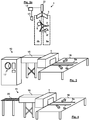
- FIG. 3 and 4 show two exemplary uses of the bottle maker Fig. 1a-d and or Fig. 2a-e , on the one hand as a component of a reverse vending machine 10 in Fig. 3 and on the other hand as a component of a sorting system 11 in Fig. 4 ,
- the exemplary reverse vending machine 10 in FIG Fig. 3 is intended for the return of bottles.
- the reverse vending machine 1 comprises a housing with an insertion opening 17, which is embedded in its front side and which is formed as a hollow cylinder for receiving empty bottles. Furthermore, outside the front of the housing, the usual components, such as a display panel and / or a dispensing opening may be attached.
- the reverse vending machine 10 comprises a conveyor belt (not shown) which forwards a bottle introduced into the insertion opening 17 to a sensor device (also not shown) by which one or more empties characteristics of the bottle are detected.
- an emptying feature may be the outer shape and weight of the bottle, any damage or residue left over, an existing bar or bar code, or a closure on the bottle.
- the reverse vending machine further comprises a control device (not shown) connected to the conveyor belt and the sensor device. This is designed to evaluate the identified by the sensor device empties feature. After the evaluation of the entered bottle, the control device either - in the case that the bottle is accepted - causes the further transport of the bottle through the conveyor belt or - in case the Bottle is rejected - the return of the bottle. If the bottle is accepted, it is forwarded via a transport device 18 to a bottle stand 1.
- the bottle stand 1 corresponds for example to that in Fig. 1a-d and / or that in Fig. 2a-e , Accordingly, the bottle is placed here and forwarded depending on the features either on the first conveyor belt 8a or the second conveyor belt 8b.
- the bottle is placed on a collecting table, where it is turned off depending on the characteristics and used conveyor belt 8a, 8b on different sides of the collecting table 19 (by arrows in Fig. 3 indicated).
- the sorting underlying characteristics can be determined, for example, by the sensor device of the automatic reverse vending machine 10, so that the transport element 2 of the bottle maker 1 based on this can make a corresponding selection.
- the sorting system 11 in Fig. 4 also has a bottle stand 1, which is fed by a transport device 18 and the bottles subsequently leads to a collecting table 19.
- the bottles are delivered in the sorting system 11 via a roller conveyor 20.
- Such a sorting system 11 can, in principle, be part of a reverse vending machine, eg, like that in FIG Fig. 3 , In principle, however, further applications are possible, for example within a production line production or the like, in which containers are to be set up and selected or sorted before they are possibly filled, for example.
Landscapes
- Physics & Mathematics (AREA)
- General Physics & Mathematics (AREA)
- Branching, Merging, And Special Transfer Between Conveyors (AREA)
- Discharge Of Articles From Conveyors (AREA)
- Sorting Of Articles (AREA)
Applications Claiming Priority (3)
| Application Number | Priority Date | Filing Date | Title |
|---|---|---|---|
| DE102018205834 | 2018-04-17 | ||
| DE102018208575.7A DE102018208575B4 (de) | 2018-04-17 | 2018-05-30 | Flaschenaufsteller, Rücknahmeautomat und Sortieranlage |
| DE102018208581.1A DE102018208581B4 (de) | 2018-04-17 | 2018-05-30 | Flaschenaufsteller, Rücknahmeautomat und Sortieranlage |
Publications (2)
| Publication Number | Publication Date |
|---|---|
| EP3557541A1 true EP3557541A1 (fr) | 2019-10-23 |
| EP3557541B1 EP3557541B1 (fr) | 2023-07-26 |
Family
ID=65818286
Family Applications (1)
| Application Number | Title | Priority Date | Filing Date |
|---|---|---|---|
| EP19163376.7A Active EP3557541B1 (fr) | 2018-04-17 | 2019-03-18 | Redresseur de bouteilles, dispositif automatique de recyclage et installation de tri |
Country Status (4)
| Country | Link |
|---|---|
| EP (1) | EP3557541B1 (fr) |
| ES (1) | ES2958823T3 (fr) |
| FI (1) | FI3557541T3 (fr) |
| PL (1) | PL3557541T3 (fr) |
Cited By (3)
| Publication number | Priority date | Publication date | Assignee | Title |
|---|---|---|---|---|
| CN115743701A (zh) * | 2022-12-20 | 2023-03-07 | 广州三拓识别技术有限公司 | 一种对称包装自动定位配瓶装置 |
| WO2024231187A1 (fr) * | 2023-05-05 | 2024-11-14 | PFABO GmbH | Dispositif et procédé pour sceller un emballage réutilisable |
| WO2024256502A1 (fr) * | 2023-06-16 | 2024-12-19 | AMI Retail Solution GmbH | Dispositif d'alignement pour aligner des contenants de marchandises vides, et système de retour de marchandises vides |
Citations (6)
| Publication number | Priority date | Publication date | Assignee | Title |
|---|---|---|---|---|
| DE69719090T2 (de) * | 1996-07-12 | 2003-12-04 | Tomra Systems Asa, Asker | Flaschenaufrichter |
| DE10061462C2 (de) | 2000-12-08 | 2003-12-11 | Prokent Ag | Leerflaschen-Rücknahmeautomat |
| DE102007009240A1 (de) * | 2006-02-22 | 2007-08-30 | Khm Transportanlagen Gmbh | Vorrichtung zum Transport beliebiger Teile |
| DE102006041888B3 (de) * | 2006-08-23 | 2008-03-27 | Wincor Nixdorf International Gmbh | Aufstellvorrichtung für Leergutbehälter |
| DE102009031479A1 (de) * | 2009-07-01 | 2011-01-05 | Krones Ag | Vorrichtung zum Anbringen von Etikettenstreifen an Behältnissen |
| EP3208783A1 (fr) * | 2016-02-19 | 2017-08-23 | Wincor Nixdorf International GmbH | Dispositif de tri de consignes et système de reprise de consignes |
Family Cites Families (1)
| Publication number | Priority date | Publication date | Assignee | Title |
|---|---|---|---|---|
| NO321229B1 (no) * | 2004-07-08 | 2006-04-10 | Repant As | Anordning ved flaskereiser |
-
2019
- 2019-03-18 PL PL19163376.7T patent/PL3557541T3/pl unknown
- 2019-03-18 FI FIEP19163376.7T patent/FI3557541T3/en active
- 2019-03-18 ES ES19163376T patent/ES2958823T3/es active Active
- 2019-03-18 EP EP19163376.7A patent/EP3557541B1/fr active Active
Patent Citations (6)
| Publication number | Priority date | Publication date | Assignee | Title |
|---|---|---|---|---|
| DE69719090T2 (de) * | 1996-07-12 | 2003-12-04 | Tomra Systems Asa, Asker | Flaschenaufrichter |
| DE10061462C2 (de) | 2000-12-08 | 2003-12-11 | Prokent Ag | Leerflaschen-Rücknahmeautomat |
| DE102007009240A1 (de) * | 2006-02-22 | 2007-08-30 | Khm Transportanlagen Gmbh | Vorrichtung zum Transport beliebiger Teile |
| DE102006041888B3 (de) * | 2006-08-23 | 2008-03-27 | Wincor Nixdorf International Gmbh | Aufstellvorrichtung für Leergutbehälter |
| DE102009031479A1 (de) * | 2009-07-01 | 2011-01-05 | Krones Ag | Vorrichtung zum Anbringen von Etikettenstreifen an Behältnissen |
| EP3208783A1 (fr) * | 2016-02-19 | 2017-08-23 | Wincor Nixdorf International GmbH | Dispositif de tri de consignes et système de reprise de consignes |
Cited By (3)
| Publication number | Priority date | Publication date | Assignee | Title |
|---|---|---|---|---|
| CN115743701A (zh) * | 2022-12-20 | 2023-03-07 | 广州三拓识别技术有限公司 | 一种对称包装自动定位配瓶装置 |
| WO2024231187A1 (fr) * | 2023-05-05 | 2024-11-14 | PFABO GmbH | Dispositif et procédé pour sceller un emballage réutilisable |
| WO2024256502A1 (fr) * | 2023-06-16 | 2024-12-19 | AMI Retail Solution GmbH | Dispositif d'alignement pour aligner des contenants de marchandises vides, et système de retour de marchandises vides |
Also Published As
| Publication number | Publication date |
|---|---|
| FI3557541T3 (en) | 2023-09-29 |
| ES2958823T3 (es) | 2024-02-15 |
| PL3557541T3 (pl) | 2023-11-27 |
| EP3557541B1 (fr) | 2023-07-26 |
Similar Documents
| Publication | Publication Date | Title |
|---|---|---|
| EP3254893B1 (fr) | Véhicule de livraison et procédé de livraison d'envois à différents endroits le long d'un itinéraire | |
| EP1765525B1 (fr) | Dispositif de tri d'envois plats | |
| EP3557541B1 (fr) | Redresseur de bouteilles, dispositif automatique de recyclage et installation de tri | |
| EP3456424B1 (fr) | Station de transfert et machine de reprise | |
| DE3517848A1 (de) | Maschine zur annahme, ausgabe und wiederausgabe von banknoten | |
| EP2704109B1 (fr) | Installation de recyclage de gerbes avec un dispositif de répartition | |
| EP1892207A2 (fr) | Dispositif destiné à la répartition et/ou le trie de rouleaux de matériau et leur transmission et un procédé de transport de rouleaux de matériau | |
| EP3953281B1 (fr) | Station de courrier par tube comprenant un échangeur d'outils | |
| AT522525B1 (de) | Pipettenspitzentrennsystem | |
| EP2002405B1 (fr) | Unite de transport dans un systeme de recuperation de produits vides | |
| EP3166736B1 (fr) | Système de manutention pour des bouteilles consignées | |
| DE102018208581B4 (de) | Flaschenaufsteller, Rücknahmeautomat und Sortieranlage | |
| EP2615586B1 (fr) | Dispositif destiné à la manipulation de monnaie avec des récipients collecteurs placés de chaque côté | |
| EP2764502A1 (fr) | Dispositif et procédé de traitement de billets de banque | |
| EP2695144B1 (fr) | Dispositif de manipulation de pièces de monnaie | |
| DE102020003557B4 (de) | Sammelvorrichtung, Wannenförderer und Verfahren zum Stapeln von Wannen | |
| EP2083401A1 (fr) | Automate de reprise pour bouteilles consignées | |
| WO2006094819A2 (fr) | Dispositif de compression axiale ou radiale de recipients | |
| EP4576032A1 (fr) | Dispositif de stockage pour stocker des produits dans un distributeur automatique combiné, automate et procédé | |
| EP4485411A1 (fr) | Dispositif de réception destiné à recevoir ou à distribuer des produits dans un automate combiné | |
| WO2004019285A1 (fr) | Appareil de tri d'objets en forme de plaquettes, en particulier de pieces de monnaie | |
| EP4002313A1 (fr) | Compartiment de stockage, dispositif de stockage et procédé de stockage d'une pluralité de récipients roulants acheminés individuellement, dispositif automatique de réception | |
| CH650747A5 (de) | Rohrpostanlage. | |
| EP2764500B1 (fr) | Dispositif de manipulation de pièces de monnaie comportant un stock intermédiaire | |
| DE102010036947A1 (de) | Vorrichtung zur Handhabung von Münzen mit mehreren Weichenmodulen |
Legal Events
| Date | Code | Title | Description |
|---|---|---|---|
| PUAI | Public reference made under article 153(3) epc to a published international application that has entered the european phase |
Free format text: ORIGINAL CODE: 0009012 |
|
| STAA | Information on the status of an ep patent application or granted ep patent |
Free format text: STATUS: THE APPLICATION HAS BEEN PUBLISHED |
|
| AK | Designated contracting states |
Kind code of ref document: A1 Designated state(s): AL AT BE BG CH CY CZ DE DK EE ES FI FR GB GR HR HU IE IS IT LI LT LU LV MC MK MT NL NO PL PT RO RS SE SI SK SM TR |
|
| AX | Request for extension of the european patent |
Extension state: BA ME |
|
| STAA | Information on the status of an ep patent application or granted ep patent |
Free format text: STATUS: REQUEST FOR EXAMINATION WAS MADE |
|
| 17P | Request for examination filed |
Effective date: 20191128 |
|
| RBV | Designated contracting states (corrected) |
Designated state(s): AL AT BE BG CH CY CZ DE DK EE ES FI FR GB GR HR HU IE IS IT LI LT LU LV MC MK MT NL NO PL PT RO RS SE SI SK SM TR |
|
| STAA | Information on the status of an ep patent application or granted ep patent |
Free format text: STATUS: EXAMINATION IS IN PROGRESS |
|
| 17Q | First examination report despatched |
Effective date: 20210426 |
|
| RAP3 | Party data changed (applicant data changed or rights of an application transferred) |
Owner name: SIELAFF GMBH & CO. KG AUTOMATENBAU HERRIEDEN |
|
| GRAP | Despatch of communication of intention to grant a patent |
Free format text: ORIGINAL CODE: EPIDOSNIGR1 |
|
| STAA | Information on the status of an ep patent application or granted ep patent |
Free format text: STATUS: GRANT OF PATENT IS INTENDED |
|
| INTG | Intention to grant announced |
Effective date: 20230214 |
|
| RAP3 | Party data changed (applicant data changed or rights of an application transferred) |
Owner name: SIELAFF GMBH & CO. KG AUTOMATENBAU HERRIEDEN |
|
| GRAS | Grant fee paid |
Free format text: ORIGINAL CODE: EPIDOSNIGR3 |
|
| GRAA | (expected) grant |
Free format text: ORIGINAL CODE: 0009210 |
|
| STAA | Information on the status of an ep patent application or granted ep patent |
Free format text: STATUS: THE PATENT HAS BEEN GRANTED |
|
| P01 | Opt-out of the competence of the unified patent court (upc) registered |
Effective date: 20230601 |
|
| AK | Designated contracting states |
Kind code of ref document: B1 Designated state(s): AL AT BE BG CH CY CZ DE DK EE ES FI FR GB GR HR HU IE IS IT LI LT LU LV MC MK MT NL NO PL PT RO RS SE SI SK SM TR |
|
| REG | Reference to a national code |
Ref country code: CH Ref legal event code: EP |
|
| REG | Reference to a national code |
Ref country code: IE Ref legal event code: FG4D Free format text: LANGUAGE OF EP DOCUMENT: GERMAN |
|
| REG | Reference to a national code |
Ref country code: DE Ref legal event code: R096 Ref document number: 502019008621 Country of ref document: DE |
|
| REG | Reference to a national code |
Ref country code: RO Ref legal event code: EPE |
|
| REG | Reference to a national code |
Ref country code: NO Ref legal event code: T2 Effective date: 20230726 |
|
| REG | Reference to a national code |
Ref country code: NL Ref legal event code: FP |
|
| REG | Reference to a national code |
Ref country code: FI Ref legal event code: FGE |
|
| REG | Reference to a national code |
Ref country code: SE Ref legal event code: TRGR |
|
| REG | Reference to a national code |
Ref country code: LT Ref legal event code: MG9D |
|
| REG | Reference to a national code |
Ref country code: EE Ref legal event code: FG4A Ref document number: E023598 Country of ref document: EE Effective date: 20230920 |
|
| REG | Reference to a national code |
Ref country code: SK Ref legal event code: T3 Ref document number: E 42350 Country of ref document: SK |
|
| PG25 | Lapsed in a contracting state [announced via postgrant information from national office to epo] |
Ref country code: GR Free format text: LAPSE BECAUSE OF FAILURE TO SUBMIT A TRANSLATION OF THE DESCRIPTION OR TO PAY THE FEE WITHIN THE PRESCRIBED TIME-LIMIT Effective date: 20231027 |
|
| PG25 | Lapsed in a contracting state [announced via postgrant information from national office to epo] |
Ref country code: IS Free format text: LAPSE BECAUSE OF FAILURE TO SUBMIT A TRANSLATION OF THE DESCRIPTION OR TO PAY THE FEE WITHIN THE PRESCRIBED TIME-LIMIT Effective date: 20231126 |
|
| PG25 | Lapsed in a contracting state [announced via postgrant information from national office to epo] |
Ref country code: RS Free format text: LAPSE BECAUSE OF FAILURE TO SUBMIT A TRANSLATION OF THE DESCRIPTION OR TO PAY THE FEE WITHIN THE PRESCRIBED TIME-LIMIT Effective date: 20230726 Ref country code: PT Free format text: LAPSE BECAUSE OF FAILURE TO SUBMIT A TRANSLATION OF THE DESCRIPTION OR TO PAY THE FEE WITHIN THE PRESCRIBED TIME-LIMIT Effective date: 20231127 Ref country code: LV Free format text: LAPSE BECAUSE OF FAILURE TO SUBMIT A TRANSLATION OF THE DESCRIPTION OR TO PAY THE FEE WITHIN THE PRESCRIBED TIME-LIMIT Effective date: 20230726 Ref country code: LT Free format text: LAPSE BECAUSE OF FAILURE TO SUBMIT A TRANSLATION OF THE DESCRIPTION OR TO PAY THE FEE WITHIN THE PRESCRIBED TIME-LIMIT Effective date: 20230726 Ref country code: IS Free format text: LAPSE BECAUSE OF FAILURE TO SUBMIT A TRANSLATION OF THE DESCRIPTION OR TO PAY THE FEE WITHIN THE PRESCRIBED TIME-LIMIT Effective date: 20231126 Ref country code: HR Free format text: LAPSE BECAUSE OF FAILURE TO SUBMIT A TRANSLATION OF THE DESCRIPTION OR TO PAY THE FEE WITHIN THE PRESCRIBED TIME-LIMIT Effective date: 20230726 Ref country code: GR Free format text: LAPSE BECAUSE OF FAILURE TO SUBMIT A TRANSLATION OF THE DESCRIPTION OR TO PAY THE FEE WITHIN THE PRESCRIBED TIME-LIMIT Effective date: 20231027 |
|
| REG | Reference to a national code |
Ref country code: ES Ref legal event code: FG2A Ref document number: 2958823 Country of ref document: ES Kind code of ref document: T3 Effective date: 20240215 |
|
| PGFP | Annual fee paid to national office [announced via postgrant information from national office to epo] |
Ref country code: NL Payment date: 20240320 Year of fee payment: 6 |
|
| REG | Reference to a national code |
Ref country code: DE Ref legal event code: R097 Ref document number: 502019008621 Country of ref document: DE |
|
| PG25 | Lapsed in a contracting state [announced via postgrant information from national office to epo] |
Ref country code: SM Free format text: LAPSE BECAUSE OF FAILURE TO SUBMIT A TRANSLATION OF THE DESCRIPTION OR TO PAY THE FEE WITHIN THE PRESCRIBED TIME-LIMIT Effective date: 20230726 Ref country code: DK Free format text: LAPSE BECAUSE OF FAILURE TO SUBMIT A TRANSLATION OF THE DESCRIPTION OR TO PAY THE FEE WITHIN THE PRESCRIBED TIME-LIMIT Effective date: 20230726 Ref country code: CZ Free format text: LAPSE BECAUSE OF FAILURE TO SUBMIT A TRANSLATION OF THE DESCRIPTION OR TO PAY THE FEE WITHIN THE PRESCRIBED TIME-LIMIT Effective date: 20230726 |
|
| PGFP | Annual fee paid to national office [announced via postgrant information from national office to epo] |
Ref country code: RO Payment date: 20240314 Year of fee payment: 6 Ref country code: FI Payment date: 20240320 Year of fee payment: 6 Ref country code: EE Payment date: 20240320 Year of fee payment: 6 |
|
| PLBE | No opposition filed within time limit |
Free format text: ORIGINAL CODE: 0009261 |
|
| STAA | Information on the status of an ep patent application or granted ep patent |
Free format text: STATUS: NO OPPOSITION FILED WITHIN TIME LIMIT |
|
| 26N | No opposition filed |
Effective date: 20240429 |
|
| PG25 | Lapsed in a contracting state [announced via postgrant information from national office to epo] |
Ref country code: SI Free format text: LAPSE BECAUSE OF FAILURE TO SUBMIT A TRANSLATION OF THE DESCRIPTION OR TO PAY THE FEE WITHIN THE PRESCRIBED TIME-LIMIT Effective date: 20230726 |
|
| REG | Reference to a national code |
Ref country code: CH Ref legal event code: PL |
|
| PG25 | Lapsed in a contracting state [announced via postgrant information from national office to epo] |
Ref country code: BG Free format text: LAPSE BECAUSE OF FAILURE TO SUBMIT A TRANSLATION OF THE DESCRIPTION OR TO PAY THE FEE WITHIN THE PRESCRIBED TIME-LIMIT Effective date: 20230726 |
|
| PG25 | Lapsed in a contracting state [announced via postgrant information from national office to epo] |
Ref country code: LU Free format text: LAPSE BECAUSE OF NON-PAYMENT OF DUE FEES Effective date: 20240318 |
|
| PG25 | Lapsed in a contracting state [announced via postgrant information from national office to epo] |
Ref country code: MC Free format text: LAPSE BECAUSE OF FAILURE TO SUBMIT A TRANSLATION OF THE DESCRIPTION OR TO PAY THE FEE WITHIN THE PRESCRIBED TIME-LIMIT Effective date: 20230726 |
|
| PG25 | Lapsed in a contracting state [announced via postgrant information from national office to epo] |
Ref country code: MC Free format text: LAPSE BECAUSE OF FAILURE TO SUBMIT A TRANSLATION OF THE DESCRIPTION OR TO PAY THE FEE WITHIN THE PRESCRIBED TIME-LIMIT Effective date: 20230726 Ref country code: LU Free format text: LAPSE BECAUSE OF NON-PAYMENT OF DUE FEES Effective date: 20240318 Ref country code: BG Free format text: LAPSE BECAUSE OF FAILURE TO SUBMIT A TRANSLATION OF THE DESCRIPTION OR TO PAY THE FEE WITHIN THE PRESCRIBED TIME-LIMIT Effective date: 20230726 |
|
| REG | Reference to a national code |
Ref country code: BE Ref legal event code: MM Effective date: 20240331 |
|
| PG25 | Lapsed in a contracting state [announced via postgrant information from national office to epo] |
Ref country code: BE Free format text: LAPSE BECAUSE OF NON-PAYMENT OF DUE FEES Effective date: 20240331 |
|
| PG25 | Lapsed in a contracting state [announced via postgrant information from national office to epo] |
Ref country code: IE Free format text: LAPSE BECAUSE OF NON-PAYMENT OF DUE FEES Effective date: 20240318 |
|
| PG25 | Lapsed in a contracting state [announced via postgrant information from national office to epo] |
Ref country code: IE Free format text: LAPSE BECAUSE OF NON-PAYMENT OF DUE FEES Effective date: 20240318 Ref country code: BE Free format text: LAPSE BECAUSE OF NON-PAYMENT OF DUE FEES Effective date: 20240331 Ref country code: CH Free format text: LAPSE BECAUSE OF NON-PAYMENT OF DUE FEES Effective date: 20240331 |
|
| PGFP | Annual fee paid to national office [announced via postgrant information from national office to epo] |
Ref country code: SE Payment date: 20250321 Year of fee payment: 7 |
|
| PGFP | Annual fee paid to national office [announced via postgrant information from national office to epo] |
Ref country code: DE Payment date: 20250331 Year of fee payment: 7 |
|
| PGFP | Annual fee paid to national office [announced via postgrant information from national office to epo] |
Ref country code: NO Payment date: 20250321 Year of fee payment: 7 |
|
| PGFP | Annual fee paid to national office [announced via postgrant information from national office to epo] |
Ref country code: AT Payment date: 20250320 Year of fee payment: 7 |
|
| PGFP | Annual fee paid to national office [announced via postgrant information from national office to epo] |
Ref country code: FR Payment date: 20250326 Year of fee payment: 7 Ref country code: PL Payment date: 20250310 Year of fee payment: 7 |
|
| PGFP | Annual fee paid to national office [announced via postgrant information from national office to epo] |
Ref country code: SK Payment date: 20250310 Year of fee payment: 7 Ref country code: IT Payment date: 20250325 Year of fee payment: 7 Ref country code: GB Payment date: 20250324 Year of fee payment: 7 |
|
| PGFP | Annual fee paid to national office [announced via postgrant information from national office to epo] |
Ref country code: ES Payment date: 20250429 Year of fee payment: 7 |
|
| PG25 | Lapsed in a contracting state [announced via postgrant information from national office to epo] |
Ref country code: CY Free format text: LAPSE BECAUSE OF FAILURE TO SUBMIT A TRANSLATION OF THE DESCRIPTION OR TO PAY THE FEE WITHIN THE PRESCRIBED TIME-LIMIT; INVALID AB INITIO Effective date: 20190318 |
|
| PG25 | Lapsed in a contracting state [announced via postgrant information from national office to epo] |
Ref country code: HU Free format text: LAPSE BECAUSE OF FAILURE TO SUBMIT A TRANSLATION OF THE DESCRIPTION OR TO PAY THE FEE WITHIN THE PRESCRIBED TIME-LIMIT; INVALID AB INITIO Effective date: 20190318 |
|
| PG25 | Lapsed in a contracting state [announced via postgrant information from national office to epo] |
Ref country code: FI Free format text: LAPSE BECAUSE OF NON-PAYMENT OF DUE FEES Effective date: 20250318 |
|
| PG25 | Lapsed in a contracting state [announced via postgrant information from national office to epo] |
Ref country code: RO Free format text: LAPSE BECAUSE OF NON-PAYMENT OF DUE FEES Effective date: 20250318 |
|
| REG | Reference to a national code |
Ref country code: NL Ref legal event code: MM Effective date: 20250401 |
|
| PG25 | Lapsed in a contracting state [announced via postgrant information from national office to epo] |
Ref country code: TR Free format text: LAPSE BECAUSE OF FAILURE TO SUBMIT A TRANSLATION OF THE DESCRIPTION OR TO PAY THE FEE WITHIN THE PRESCRIBED TIME-LIMIT Effective date: 20230726 |
|
| PG25 | Lapsed in a contracting state [announced via postgrant information from national office to epo] |
Ref country code: NL Free format text: LAPSE BECAUSE OF NON-PAYMENT OF DUE FEES Effective date: 20250401 |
|
| PG25 | Lapsed in a contracting state [announced via postgrant information from national office to epo] |
Ref country code: EE Free format text: LAPSE BECAUSE OF NON-PAYMENT OF DUE FEES Effective date: 20250331 |