EP4485411A1 - Dispositif de réception destiné à recevoir ou à distribuer des produits dans un automate combiné - Google Patents
Dispositif de réception destiné à recevoir ou à distribuer des produits dans un automate combiné Download PDFInfo
- Publication number
- EP4485411A1 EP4485411A1 EP24183969.5A EP24183969A EP4485411A1 EP 4485411 A1 EP4485411 A1 EP 4485411A1 EP 24183969 A EP24183969 A EP 24183969A EP 4485411 A1 EP4485411 A1 EP 4485411A1
- Authority
- EP
- European Patent Office
- Prior art keywords
- product
- receiving
- opening
- receiving unit
- guide
- Prior art date
- Legal status (The legal status is an assumption and is not a legal conclusion. Google has not performed a legal analysis and makes no representation as to the accuracy of the status listed.)
- Pending
Links
Images


Classifications
-
- G—PHYSICS
- G07—CHECKING-DEVICES
- G07F—COIN-FREED OR LIKE APPARATUS
- G07F7/00—Mechanisms actuated by objects other than coins to free or to actuate vending, hiring, coin or paper currency dispensing or refunding apparatus
- G07F7/06—Mechanisms actuated by objects other than coins to free or to actuate vending, hiring, coin or paper currency dispensing or refunding apparatus by returnable containers, i.e. reverse vending systems in which a user is rewarded for returning a container that serves as a token of value, e.g. bottles
-
- G—PHYSICS
- G07—CHECKING-DEVICES
- G07F—COIN-FREED OR LIKE APPARATUS
- G07F11/00—Coin-freed apparatus for dispensing, or the like, discrete articles
- G07F11/02—Coin-freed apparatus for dispensing, or the like, discrete articles from non-movable magazines
- G07F11/04—Coin-freed apparatus for dispensing, or the like, discrete articles from non-movable magazines in which magazines the articles are stored one vertically above the other
- G07F11/16—Delivery means
- G07F11/165—Delivery means using xyz-picker or multi-dimensional article picking arrangements
Definitions
- the present invention relates to a receiving device for receiving or dispensing products in a combination machine. Furthermore, the invention relates to a method for returning or dispensing products using a combination machine.
- vending machines or vending machines for short, which are often also referred to as self-sellers, have long been used to sell food, drinks, cigarettes or other items and can be designed in a variety of different ways, such as candy machines, drinks machines, cigarette machines, general store machines and the like. In the case of a combination machine, deposit items can also be returned to the machine.
- the deposit items can be products such as PET bottles, CO2 bottles, glass bottles, beverage cans, reusable items or similar, which are to be collected in a return system.
- the DE 11 37 588 B shows a vending machine with a drawer for vertically stored goods.
- the drawer is pulled out manually using the handle and can be moved along rails.
- the product is moved upwards to the outlet via a movable base that is pivoted.
- the movable base is guided by a guide pin in a bent slot.
- FIG. 17 02 485 U Another vending machine is shown that has a drawer with a pivoting level.
- the drawer should not be pushed back when there is still product in it. This is done by a pivoting level that forms a lever that is blocked in the tilted position by a locking pawl. If the product is removed, the lever pivots into the horizontal position, allowing the drawer to be pushed back in again.
- the object of the present invention is to provide an improved intake or dispensing of products in a combination vending machine.
- this object is achieved by a receiving device having the features of patent claim 1 and/or by a method having the features of patent claim 14.
- the finding underlying the present invention is that the transport unit can move the receiving unit to different positions within the combination machine in order to dispense or pick up at least one product and to transport the product beforehand or subsequently to a desired position within the combination machine.
- the idea underlying the present invention is to couple the receiving unit to the transport unit in such a way that a product stored in the receiving unit can be released through an opening in the transport unit, in particular into a collecting container or at least one shaft, and preferably in a downward or upward direction.
- the product can in particular be a deposit container such as a CO2 bottle or other goods that are designed for multiple use.
- such a receiving device can be used to receive deposit containers or goods in an aligned manner so that the deposit containers can then be stored in an aligned manner on top of each other and next to each other. This prevents damage to the deposit containers and at the same time allows for space-saving storage.
- the opening in the transport unit can be a passage that is arranged directly below the receiving unit.
- the opening is preferably larger than a product or deposit product, so that the product can be transported through the opening, particularly when lying down. If, for example, it is a CO2 combination machine, the opening is preferably designed in such a way that a bottle or cylinder can be transported vertically downwards or upwards through the opening when lying down.
- the opening can be provided as a rectangular opening in the transport unit.
- the opening can also have any shape.
- the transport unit can have a carriage, wherein the opening is arranged on a bottom side of the carriage.
- the carriage is designed in particular to move the transport unit along a specific direction.
- the direction runs in particular transversely to the direction in which the receiving unit can be moved towards the dispensing opening or away from it.
- the carriage can be designed to move the receiving unit towards or away from the dispensing opening and to move the transport unit transversely to the dispensing opening.
- the at least one product can be dispensed at a desired position within the combination machine, which can be selected independently of the dispensing opening.
- the transport unit can have at least one guide element, wherein the receiving unit can be moved along the guide element.
- the guide elements are in particular integrated with the carriage.
- the guide elements can be designed, for example, as angled sheet metal elements on which the receiving unit can be supported or latched. If the opening is provided as a rectangular opening in the transport unit, the guide elements can be formed on two opposite sides of the opening, in particular as bent sheet metal parts, which can be formed from the material for forming the opening.
- two guide elements can be designed as stop elements, wherein the receiving unit has rollers that can be guided along the stop elements.
- the stop elements can be formed as a type of undercut, in particular as angled sheet metal elements.
- the stop elements can hold the receiving unit at a desired position with respect to the unit, in particular with respect to the carriage, since these are held against vertical movement by the stop elements.
- the stop elements form limiting elements that prevent the receiving unit from being moved vertically upwards.
- the transport unit itself prevents the receiving unit from being moved vertically downwards. This allows the receiving unit to be moved back and forth in a rail between the stop elements and the transport unit.
- the transport unit can be mounted on at least one guide rail, so that the transport unit can be moved transversely to the dispensing opening. This allows the product to be moved to any position inside or outside the machine in order to be dispensed through the opening. Furthermore, a product can be placed into the receiving unit from any position inside or outside the machine and then moved to the dispensing opening.
- a guide contour can be formed on the at least one guide rail and the receiving unit can have at least one guide pin, so that when the guide pin comes into contact along the guide contour, the receiving unit can be moved in the direction of the dispensing opening. This allows the product to be moved automatically towards the dispensing opening, so that ergonomic removal or insertion of the product can be ensured. An additional motorized unit for this movement can therefore be dispensed with.
- the guide rails can be arranged parallel to one another, whereby one of the guide rails can be arranged closer to the dispensing opening than the other guide rail.
- the guide contour can be formed in one piece with the at least one guide rail, in particular with the guide rail that is arranged further away from the dispensing opening.
- the guide contour can also be formed as a separate component that is attached to the at least one guide rail, in particular screwed or welded.
- the guide contour can preferably be arranged between the two guide rails in order to come into contact with the guide pin that is arranged on the transport unit.
- the guide contour can be formed in an edge region of the at least one guide rail, so that the product can be dispensed or picked up in the edge region.
- the guide rails can thus be arranged, for example, parallel to a front side of the combination machine within the combination machine, wherein the dispensing opening can be arranged on a right or left side of the combination machine.
- the guide contour can describe a partial circular shape at least in sections, so that the guide pin is moved by contact along the guide contour in the direction of the dispensing opening. This can prevent the pin from getting caught in the guide contour if the guide contour is designed as a continuous shape. It can also prevent the receiving unit from being moved forwards in a jerky manner in the direction of the dispensing opening, which prevents the product from falling out.
- the receiving unit can be movable relative to the transport unit by contact of the guide pin along the guide contour.
- the receiving unit can be moved within the guide elements by the contact between the guide pin and the guide contour.
- the receiving unit can have a pivoting device, wherein the pivoting device can be pivoted in the direction of the opening so that the product can be dispensed through the opening.
- the pivoting device can be mounted on one side so that a pivot axis is formed. From this one-sided mounting, the pivoting device can be designed as a type of cantilever arm, wherein the pivoting device preferably forms a support surface for the at least one product.
- the pivoting device can, for example, have a recess so that secure reception of the product can be ensured. If the pivoting device is now pivoted in the direction of the opening, the product is released from the recess and conveyed through the opening.
- the pivot axis is preferably aligned horizontally so that the product can be dispensed downwards by pivoting downwards about a horizontal axis. Likewise, the product can be dispensed upwards by pivoting upwards.
- the support surface can be curved in such a way that on the one hand the recess is formed and on the other hand at least one rolling edge is formed over which the product can slide or roll.
- the pivoting device can have a recess, with a rolling edge being formed on two opposite sides of the recess. This allows the product to be rolled off the swivel device and can be released upwards or downwards in particular.
- the pivoting device can be held in a frame, the frame being open on one side so that the product can be dispensed through the dispensing opening on this open side.
- Open means that the frame is not formed all the way around, but only has three sides.
- the frame is preferably part of the receiving unit and can be U-shaped, for example.
- the product can also be placed on the pivoting device through the dispensing opening and in particular can be inserted or fed into the receiving device.
- the pivoting device can protrude beyond the frame on the open side.
- the frame does not have to be moved all the way to the dispensing opening in order to store the product stored on the pivoting device within reach of the dispensing opening.
- the swivel device can be driven by an electric motor, wherein a drive shaft of the electric motor is connected to the swivel device, so that the swivel device can be deflected about the drive shaft by rotation of the drive shaft.
- the drive shaft can form the swivel axis.
- the transport unit can be mounted on at least one guide rail, so that the transport unit can be moved transversely to the dispensing opening, wherein a guide contour is formed on the at least one guide rail and the receiving unit has at least one guide pin, so that upon contact of the guide pin along the guide contour the receiving unit is moved in the direction of the dispensing opening and the product can be removed or inserted through the dispensing opening.
- Fig. 1 shows an embodiment of a receiving unit 3.
- the receiving unit 3 is designed to receive a product 2, which can be designed in particular as a deposit product, such as a CO2 bottle.
- the receiving unit 3 has a pivoting device 14, which is mounted on a frame 15. The mounting takes place on a drive shaft 16 of an electric motor, wherein the drive shaft 16 simultaneously forms a pivot axis 17 for the pivoting device 14.
- the frame 15 is open on one side, so that the pivoting device 14 protrudes beyond the frame 15 on the open side. This can ensure easier removal of the product 2 from a combination machine, as for example in Fig. 13 shown.
- Rollers 10 are arranged on the frame 15 so that the receiving unit 3 can be moved relative to a transport unit 5, as shown in Figure 2 shown, can be moved.
- four rollers 10 can be provided, with one roller 10 each being arranged in a corner region of the frame 15.
- the rollers 10 are preferably located on one plane in order to form a plane of movement.
- Fig. 2 shows an embodiment of a receiving device 1.
- the receiving unit 3 is mounted in the transport unit 5.
- the receiving unit 3 can be moved automatically by the transport unit 5 at least in the direction of a dispensing opening of the combination machine and/or away from the dispensing opening.
- the transport unit 5 has guide elements 8 in which the rollers 10 can be mounted.
- the guide elements 8 can be designed, for example, as stop elements 9, wherein a vertical displacement of the rollers 10 upwards is prevented by the stop elements 9. A vertical displacement of the rollers 10 downwards is prevented by the transport unit 5, so that guide rails are formed for the rollers 10.
- the guide elements 8 can be formed as L-shaped bent sheet metal elements which are made from the material taken from an opening 6.
- the product 2, which is stored on the pivoting device 14 of the receiving unit 3, can be delivered through the opening 6.
- the product 2 can be delivered downwards through the opening 6, in particular into a collecting container or a shaft. This allows the products 2 to be stored in an aligned manner.
- Fig. 3 shows a side view of the embodiment of the receiving device 1 from Fig. 2 , whereby the swivel device 14 can be seen in a cross-section.
- the swivel device 14 is therefore designed as a type of cantilever arm, which is mounted on the drive shaft 16.
- the cantilever arm forms a support surface for the product 2 and, in particular, has a recess for this purpose. This allows the product 2 to be stored securely on the swivel device 14.
- the recess can, for example, be V-shaped, so that the product 2 can be prevented from rolling to the right or left.
- Fig. 4 shows another side view of the embodiment of the receiving device 1 from Fig. 2
- An electric motor 18 is provided outside the frame 15 to control the drive shaft 16.
- the product 2 protrudes from the frame 15 on the open side of the frame 15 so that it can be ergonomically guided to a dispensing opening.
- the receiving unit 3 has a guide pin 13 on the underside which is Figures 9-12 is described in more detail.
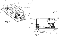
- Fig. 5 shows a further view of the embodiment of the receiving device 1 from Fig. 2 .
- the electric motor 18 and the guide pin 3 are located in a rear area of the receiving unit 3 or the transport unit 5, wherein these elements are arranged outside the frame 15.
- the drive shaft 16 is in particular positively connected to the swivel device 14, so that a movement of the drive shaft 16 is directly converted into a movement of the swivel device 14.
- the drive can also be carried out by a gear, belt or worm, for example.
- a drive with a rack, a cable, hydraulic or pneumatic is also conceivable.
- Fig. 6 shows the receiving device 1 during the dispensing of a product 2.
- the product 2 is dispensed through the opening 6 downwards through the transport unit 5.
- the dispensing takes place in particular between the two guide elements 8 and between the rollers 10.
- the pivoting device 14 can therefore be moved through the opening 6 in order to dispense the product. This is shown in the following Figure 7 shown.
- Fig. 7 shows the receiving device 1 during the dispensing of a product 2.
- the product 2 rolls over a rolling edge of the pivoting device 14 and can then be collected, for example, in a container or a shaft.
- Fig. 8 shows the receiving device 1 during the dispensing of a product 2 in a further embodiment.
- the product 2 is dispensed upwards and can also roll off the pivoting device 14 at a further rolling edge.
- the pivoting device 14 can have a rolling edge so that the product 2 can be dispensed on two opposite sides of the pivoting device 14.
- One of the rolling edges serves to dispense the product downwards through the opening 6, the other opposite rolling edge serves to dispense the product 2 upwards independently of the opening 6.
- the Figures 9 to 12 show the transport unit 5 mounted on guide rails 11.
- the guide rails 11 are arranged parallel to each other, whereby the guide rail shown in the figures can be arranged closer to a discharge opening.
- the discharge opening 4 is, for example, in Figure 13 , whereby the position of the guide rails 11 in the combination machine 19 can be clarified.
- the transport unit 5 can be moved towards the dispensing opening 4 by the guide rails 11 in order to enable a product 2 to be placed on the receiving unit 3. Furthermore, the transport unit 5 can be moved transversely to the dispensing opening 4 in order to dispense the product 2 at any position inside or outside the machine. The directions of travel are indicated by the arrows in Figure 10 shown.
- the Figures 11 and 12 show a guide contour 12 that is provided between the two guide rails 11.
- the guide contour 12 can be formed in one piece with a guide rail 11.
- the guide contour 12 can also be welded to the guide rail 11 or screwed to it.
- the guide contour 12 is designed as a component that has a side edge that is at least partially circular.
- the guide pin 13 can be guided along this side edge, which triggers a movement of the receiving unit 3.
- the guide pin 13 is therefore arranged on the receiving unit 3 so that the receiving unit 3 can be moved in the direction of the output opening 4 when the guide pin contacts the guide contour and the transport unit 5 is moved along the guide rails 11.
- a movement of the transport unit 5 in a first direction of movement can trigger a movement of the receiving unit 3 in a second direction of movement.
- the two directions of movement are directed in particular transversely to one another. This allows the product 2 to be moved towards the receiving opening 4 on the one hand and at least partially through the receiving opening 4 on the other. This ensures that the product can be removed or inserted easily and ergonomically.
- the product 2 projects beyond the guide rail 11 when the transport unit 5 is arranged on a side area on which the guide contour 12 is located.
- the product 2 can be delivered downwards through the opening 6, namely when the transport unit 5 is located at a position where the guide contour 12 is not arranged.
- the guide contour 12 is preferably aligned horizontally, so that the guide pin 13 can be guided horizontally along the guide contour 12.
- Fig. 13 shows an embodiment of the combination machine 19 with a receiving device 1.
- the interior of the combination machine 19 is shown in the area of the dispensing opening 4.
- the receiving device 1 can be seen.
- the receiving device 1 is in this illustration, for example, in the position as in Figure 12 shown.
- the product 2 can be moved towards a front side 20 of the combination machine 19 by means of the receiving device 1. and thereby move closer to the dispensing opening 4. Due to the possibility of moving the receiving unit 3 relative to the transport unit 5, the product 2 can also be moved away from the dispensing opening 4 in order to then be dispensed at any position within the combination machine 19. This position can also be reached via guide rails 11, along which the transport unit 5 can be moved.
- contour guides can be formed by different guide contours 12. This allows the depth of the machine to be optimally utilized. Furthermore, it can be possible for the pivoting device 14 to protrude through the dispensing opening 4 in order to enable the product 2 to be easily inserted or removed. The pivoting device can then be moved backwards away from the dispensing opening 4 in order to move the receiving unit 3 within the machine.
- sensors or at least a light barrier can be provided to detect what type of product has been inserted into the receiving unit 3.
- the detected product 2 can then be sorted in a targeted manner or, if necessary, rejected. For example, an incorrectly inserted product or even garbage can be detected, which should therefore not be introduced into the combination machine 19.
- a product that has been incorrectly identified can be discharged upwards rather than downwards, or vice versa.
- the swivel device 14 can therefore be used for sorting, whereby a selection of products can be discharged upwards and another selection of products can be discharged downwards.
- Individual products can also be disposed of in a waste container, for example.
- stepless travel options enable gentle handling of the products 2, whereby the holding device 1 is also suitable for glass bottles.
Landscapes
- Physics & Mathematics (AREA)
- General Physics & Mathematics (AREA)
- Vending Machines For Individual Products (AREA)
Applications Claiming Priority (1)
| Application Number | Priority Date | Filing Date | Title |
|---|---|---|---|
| DE102023116710.3A DE102023116710A1 (de) | 2023-06-26 | 2023-06-26 | Aufnahmevorrichtung zur Aufnahme oder Abgabe von Produkten in einem Kombiautomaten |
Publications (1)
| Publication Number | Publication Date |
|---|---|
| EP4485411A1 true EP4485411A1 (fr) | 2025-01-01 |
Family
ID=91664556
Family Applications (1)
| Application Number | Title | Priority Date | Filing Date |
|---|---|---|---|
| EP24183969.5A Pending EP4485411A1 (fr) | 2023-06-26 | 2024-06-24 | Dispositif de réception destiné à recevoir ou à distribuer des produits dans un automate combiné |
Country Status (2)
| Country | Link |
|---|---|
| EP (1) | EP4485411A1 (fr) |
| DE (1) | DE102023116710A1 (fr) |
Citations (8)
| Publication number | Priority date | Publication date | Assignee | Title |
|---|---|---|---|---|
| DE1702485U (de) | 1955-04-06 | 1955-07-14 | Aba Syst Throener Schneidereit | Warenverkaufsautomat mit herausziehbaren schubfaechern. |
| DE1137588B (de) | 1960-06-18 | 1962-10-04 | Gruenig Automaten Dieter | Schubfach fuer Selbstverkaeufer mit senkrechten Warenstapeln |
| DE202006018119U1 (de) * | 2006-11-29 | 2007-02-01 | Loetec Elektronische Fertigungssysteme Gmbh | Annahmeeinrichtung für Rücknahmeautomaten für zumindest nahezu achssymmetrische Rotationskörper |
| EP2107534A1 (fr) * | 2008-04-05 | 2009-10-07 | Wincor Nixdorf International GmbH | Automate de reprise pour bouteilles consignées |
| US20160182861A1 (en) * | 2014-12-17 | 2016-06-23 | Wincor Nixdorf International Gmbh | Reverse vending machine |
| WO2020089425A1 (fr) * | 2018-10-31 | 2020-05-07 | Tomra Systems Asa | Distributeur automatique inverse et procédé de fonctionnement d'un distributeur automatique inverse |
| US20210256792A1 (en) * | 2018-08-29 | 2021-08-19 | Swyft Inc. | Automated store technologies |
| US20220058604A1 (en) * | 2020-08-18 | 2022-02-24 | Dov Z. Glucksman | Autonomous Food Station |
-
2023
- 2023-06-26 DE DE102023116710.3A patent/DE102023116710A1/de active Pending
-
2024
- 2024-06-24 EP EP24183969.5A patent/EP4485411A1/fr active Pending
Patent Citations (8)
| Publication number | Priority date | Publication date | Assignee | Title |
|---|---|---|---|---|
| DE1702485U (de) | 1955-04-06 | 1955-07-14 | Aba Syst Throener Schneidereit | Warenverkaufsautomat mit herausziehbaren schubfaechern. |
| DE1137588B (de) | 1960-06-18 | 1962-10-04 | Gruenig Automaten Dieter | Schubfach fuer Selbstverkaeufer mit senkrechten Warenstapeln |
| DE202006018119U1 (de) * | 2006-11-29 | 2007-02-01 | Loetec Elektronische Fertigungssysteme Gmbh | Annahmeeinrichtung für Rücknahmeautomaten für zumindest nahezu achssymmetrische Rotationskörper |
| EP2107534A1 (fr) * | 2008-04-05 | 2009-10-07 | Wincor Nixdorf International GmbH | Automate de reprise pour bouteilles consignées |
| US20160182861A1 (en) * | 2014-12-17 | 2016-06-23 | Wincor Nixdorf International Gmbh | Reverse vending machine |
| US20210256792A1 (en) * | 2018-08-29 | 2021-08-19 | Swyft Inc. | Automated store technologies |
| WO2020089425A1 (fr) * | 2018-10-31 | 2020-05-07 | Tomra Systems Asa | Distributeur automatique inverse et procédé de fonctionnement d'un distributeur automatique inverse |
| US20220058604A1 (en) * | 2020-08-18 | 2022-02-24 | Dov Z. Glucksman | Autonomous Food Station |
Also Published As
| Publication number | Publication date |
|---|---|
| DE102023116710A1 (de) | 2025-01-02 |
Similar Documents
| Publication | Publication Date | Title |
|---|---|---|
| DE60208834T2 (de) | Zuführvorrichtung für Infusions- und Transfusionsflaschen | |
| DE10136354B4 (de) | Verfahren und Anlage zum Kommissionieren mit einem Behälterregal und zugeordnetem Regalbediengerät | |
| EP2401116B1 (fr) | Distributeur automatique d'outils modulaire | |
| EP3254893B1 (fr) | Véhicule de livraison et procédé de livraison d'envois à différents endroits le long d'un itinéraire | |
| EP2794433B1 (fr) | Installation de préparation des commandes et procédé de préparation des marchandises commandées | |
| EP3106241B1 (fr) | Machine-outil et procédé destinés a l'évacuation de parties d'une pièce à usiner | |
| EP4126719B1 (fr) | Procédé pour trier des articles et dispositif de tri | |
| EP0077554B1 (fr) | Dispositif pour le vidage de réceptacles | |
| DE20112328U1 (de) | Kommissionieranlage mit einem Behälterregal und zugeordnetem Regalbediengerät | |
| EP1322538B1 (fr) | Dispositif et procede permettant de charger l'unite d'entree d'une installation de tri d'envois | |
| DE202005008141U1 (de) | Warenbehälter zur Selbstbedienunsentnahme | |
| DE3530624C2 (fr) | ||
| EP3418227B1 (fr) | Robot transporteur sur rail et procédé de fonctionnement d'un robot transporteur sur rail | |
| EP1423314B1 (fr) | Magasin a rayonnage comportant des tiroirs montes dans les compartiments de rayonnage | |
| DE60102601T2 (de) | Verfahren und Vorrichtung zum Fördern von Gegenständen | |
| EP1322537B1 (fr) | Unite d'entree d'une installation de tri d'envois et son procede de chargement | |
| EP4485411A1 (fr) | Dispositif de réception destiné à recevoir ou à distribuer des produits dans un automate combiné | |
| EP1404596B1 (fr) | Gerbeur et procede permettant de desservir un rayonnage d'entrepot notamment un dispositif de preparation de commandes | |
| EP2002405A1 (fr) | Unite de transport dans un systeme de recuperation de produits vides | |
| DE3114718A1 (de) | "vorrichtung zum stapeln von blechzuschnitten bei tafelscheren" | |
| EP3159856A1 (fr) | Unite d'introduction pour un automate de reprise pour bouteilles consignees et automate de reprise pour bouteilles consignees | |
| EP1652799B1 (fr) | Dispositif pour individualiser des marchandises | |
| EP3166736A1 (fr) | Manutention d'emballages vides pour des systèmes de reprise | |
| EP4576032A1 (fr) | Dispositif de stockage pour stocker des produits dans un distributeur automatique combiné, automate et procédé | |
| DE10134602A1 (de) | Bandförderer für Stückgut |
Legal Events
| Date | Code | Title | Description |
|---|---|---|---|
| PUAI | Public reference made under article 153(3) epc to a published international application that has entered the european phase |
Free format text: ORIGINAL CODE: 0009012 |
|
| STAA | Information on the status of an ep patent application or granted ep patent |
Free format text: STATUS: THE APPLICATION HAS BEEN PUBLISHED |
|
| AK | Designated contracting states |
Kind code of ref document: A1 Designated state(s): AL AT BE BG CH CY CZ DE DK EE ES FI FR GB GR HR HU IE IS IT LI LT LU LV MC ME MK MT NL NO PL PT RO RS SE SI SK SM TR |
|
| STAA | Information on the status of an ep patent application or granted ep patent |
Free format text: STATUS: REQUEST FOR EXAMINATION WAS MADE |
|
| 17P | Request for examination filed |
Effective date: 20250424 |