EP4576032A1 - Dispositif de stockage pour stocker des produits dans un distributeur automatique combiné, automate et procédé - Google Patents
Dispositif de stockage pour stocker des produits dans un distributeur automatique combiné, automate et procédé Download PDFInfo
- Publication number
- EP4576032A1 EP4576032A1 EP24218326.7A EP24218326A EP4576032A1 EP 4576032 A1 EP4576032 A1 EP 4576032A1 EP 24218326 A EP24218326 A EP 24218326A EP 4576032 A1 EP4576032 A1 EP 4576032A1
- Authority
- EP
- European Patent Office
- Prior art keywords
- receiving unit
- storage unit
- unit
- storage
- product
- Prior art date
- Legal status (The legal status is an assumption and is not a legal conclusion. Google has not performed a legal analysis and makes no representation as to the accuracy of the status listed.)
- Pending
Links
Images


Classifications
-
- G—PHYSICS
- G07—CHECKING-DEVICES
- G07F—COIN-FREED OR LIKE APPARATUS
- G07F7/00—Mechanisms actuated by objects other than coins to free or to actuate vending, hiring, coin or paper currency dispensing or refunding apparatus
- G07F7/06—Mechanisms actuated by objects other than coins to free or to actuate vending, hiring, coin or paper currency dispensing or refunding apparatus by returnable containers, i.e. reverse vending systems in which a user is rewarded for returning a container that serves as a token of value, e.g. bottles
-
- G—PHYSICS
- G07—CHECKING-DEVICES
- G07F—COIN-FREED OR LIKE APPARATUS
- G07F11/00—Coin-freed apparatus for dispensing, or the like, discrete articles
- G07F11/02—Coin-freed apparatus for dispensing, or the like, discrete articles from non-movable magazines
- G07F11/04—Coin-freed apparatus for dispensing, or the like, discrete articles from non-movable magazines in which magazines the articles are stored one vertically above the other
- G07F11/16—Delivery means
Definitions
- the present invention relates to a storage device for storing products in a combination vending machine. Furthermore, the invention relates to a machine and a method for returning or dispensing products using a combination vending machine.
- vending machines or simply vending machines, often referred to as self-service machines, have long been used for the sale of food, beverages, cigarettes, or other items. They can be designed in a variety of different ways, such as candy machines, beverage machines, cigarette machines, general merchandise machines, and the like. Combined vending machines also allow deposits to be returned to the machine.
- the deposit items can be products such as PET bottles, CO2 bottles, glass bottles, beverage cans, reusable items or similar, which are to be collected in a return system.
- Combination vending machines are designed to dispense products on the one hand and store returned products on the other.
- a storage device is particularly necessary when more products are dispensed than are dispensed, i.e., more products are returned to the combination vending machine than are dispensed from the combination vending machine.
- a storage device is necessary if only products are handed out or taken back without any products being dispensed in between, referred to as collective delivery.
- combo vending machines unlike deposit return machines, combo vending machines typically do not have a conveyor belt or drop-in bin, meaning the products cannot be stored.
- a CO2 combo vending machine in which products can only be sorted into the designated chutes once they have been removed from the chute. However, this removal from the chutes should only take place once the products have been dispensed.
- the object of the present invention is to provide an improved receiving or dispensing of products in a combination vending machine.
- this object is achieved by a storage device having the features of patent claim 1 and/or by a machine having the features of patent claim 13 and/or by a method having the features of patent claim 14.
- the finding underlying the present invention is that a storage device can create the possibility of accepting products collectively in a combination vending machine without having to dispense a product in between.
- the idea underlying the present invention is to design a receiving unit for contact with a storage unit so that the products can be transported from the receiving unit to the storage unit and vice versa.
- such a storage device allows for the aligned transfer of products, particularly deposit containers or goods, in such a way that the deposit containers can then be stored aligned on top of each other or next to each other. This prevents damage to the deposit containers and simultaneously allows for space-saving storage.
- the input opening can be a passage located in the front area of the combination vending machine.
- the product can be inserted through the input opening, particularly in a horizontal position.
- the receiving unit is, in particular, a unit onto which the products are placed when they are inserted into the combi-machine through the input opening. Furthermore, the products can be removed from the receiving unit through the input opening.
- the storage unit is, in particular, a unit located inside the combination machine and is not accessible by a customer or from outside.
- the storage unit is therefore used in particular for temporary storage of products before they are sorted into appropriate shafts or stored in collection containers.
- the receiving unit and the storage unit are preferably aligned with each other in the combination machine in such a way that a transfer of at least one product from the receiving unit to the storage unit or from the storage unit to the receiving unit can be made possible.
- a transfer area can be formed which is made possible by contact from the corresponding edge areas.
- the product in particular a CO2 cylinder, can roll from the receiving unit to the storage unit once the product has been placed on the receiving unit and is then to be temporarily stored in the combination vending machine. Furthermore, the product, in particular a CO2 cylinder, can roll from the storage unit to the receiving unit when the product is to be dispensed.
- the receiving unit and the storage unit can therefore be arranged in at least two positions relative to one another.
- the two positions are determined, in particular, by the receiving unit and storage unit being aligned differently relative to one another, so that a respective transfer area is formed that enables a different movement of the product, in particular a different rolling or sliding movement of the product, in different directions based solely on gravity.
- the respective transfer area is located in particular in the area in which the two edge areas contact each other
- Corresponding edge regions are designed, in particular, to enable transfer from the receiving unit to the storage unit and vice versa. Accordingly, upon contact of the corresponding edge regions, a rollover surface is formed, which enables the product to roll over.
- the number of storage units can vary, whereby in particular a plurality of storage units can be provided next to one another or one above the other in order to temporarily store a plurality of products.
- the receiving unit can have a first pivoting device so that the receiving unit can be pivoted in the direction of the storage unit.
- an upward or downward pivoting direction can be enabled so that a product can be transferred from a receiving unit to a storage unit. If the receiving unit is located below the storage unit, a pivoting direction or pivoting movement takes place upwards, for example, in order to transfer the product from the receiving unit to the storage unit.
- a downward pivoting movement can be enabled if the receiving unit is located above the storage unit and a product is to be transferred from the receiving unit to the storage unit.
- the storage unit and the receiving unit can also be arranged next to one another.
- the storage unit can have a second pivoting device so that the storage unit can be pivoted upon contact with the receiving unit.
- the storage unit can also be pivoted to enable contact between the corresponding edge regions in the at least two different positions.
- the two pivoting devices are aligned with each other such that the respective pivot axes are arranged parallel to each other.
- the two pivot axes can also be aligned transversely or at an angle to each other.
- the first pivoting device can be arranged in the region of a first edge region on the receiving unit. This makes it possible, in particular, for a product to be guided over the receiving unit in the region where the first pivoting device is arranged.
- a type of rollover area can be formed above the first pivoting device.
- the edge region of the receiving unit can be located in the region of the first pivoting device.
- the second pivoting device can be arranged opposite a second edge region on the storage unit. This can in particular make it possible for a product to be guided over the storage unit in the region arranged opposite the second pivoting device.
- a type of roll-over region can be formed on the storage unit opposite the second pivoting device. In this way, in particular, the edge region of the storage unit can contact the edge region of the first pivoting device without the second pivoting device making it difficult to transfer the product. This is particularly advantageous when the receiving unit is arranged below or next to the storage unit.
- the second pivoting device of the storage unit can be designed to be self-resetting.
- Self-resetting means, in particular, that the storage unit rotates back to its original position after contact between the storage unit and the receiving unit, without the need for a drive element.
- At least one return element such as a return spring or tension spring, can be provided to automatically return the storage unit to its original position.
- the return element is located in particular in the area of the second pivoting device, so that a self-resetting rotation of the storage unit can be enabled in a space-saving manner.
- the corresponding edge regions can form a first inclined plane when the receiving unit comes into contact with the storage unit in the first position and a second inclined plane in the second position.
- An inclined plane enables, in particular, the rolling or sliding of a cylindrical or otherwise shaped product from the receiving unit to the storage unit or vice versa.
- An inclined plane is made possible, in particular, by contact between the mutually corresponding edge regions, wherein sections of the receiving unit and the storage unit adjacent to the edge regions can form the inclined plane.
- the storage unit and the receiving unit are each pivoted in such a way that they are aligned at a desired angle to one another in order to form a continuous inclined plane.
- a gradient of the first inclined plane can be oriented opposite to a gradient of the second inclined plane. This allows rolling or sliding in two essentially opposite directions.
- the receiving unit can be pivoted, for example, through a rotation angle of 90° to 120°, in particular through 110°, in particular pivoted upwards.
- the edge region of the receiving unit can contact the storage unit, i.e., the edge region of the storage unit.
- This can, for example, trigger a rotation of the storage unit.
- the storage unit can be deflected such that the first position is formed, wherein the first inclined plane has a gradient of 1° to 10°, in particular 3° to 5°, preferably 4° or 5°. Under such a gradient, the product can roll or slide onto the storage unit, for example, solely under gravity. Other gradient angles are equally suitable for enabling the product to roll or slide.
- the receiving unit in particular for transferring a product from the storage unit to the receiving unit, can be pivoted, for example, by a rotation angle of less than 90°, in particular by 70° to 85°, preferably 80°, in particular pivoted upwards.
- the edge region of the receiving unit can contact the storage unit, i.e. the edge region of the storage unit.
- This can trigger a rotation of the storage unit, wherein the rotation is different from the previously described rotation in the first position.
- the storage unit can be deflected such that the second position is formed, wherein the second inclined plane has a gradient of 1° to 10°, in particular 3° to 5°, preferably 4° or 5°. Under such a gradient, the product can be transferred onto the receiving unit, for example, alone Roll or slide due to gravity. Other slope angles are also suitable for allowing the product to roll or slide.
- the different inclined planes are achieved in particular by the fact that the recording unit and the storage unit are arranged differently relative to each other, in particular by being deflected in different rotational directions.
- the distance between the receiving unit and the storage unit is configured differently in the first position and the second position, so that, in combination with the different deflection of the storage unit and the receiving unit, the first and second inclined planes can be achieved.
- a transport unit can be provided for this purpose, in particular.
- the gradient of the first and/or second inclined plane can therefore be 5° to 10°, in particular more than 10°, in order to enable sliding or gliding on the surface of the inclined plane, depending on the product geometry.
- the storage unit and the receiving unit can each have at least one contact surface at the corresponding edge regions, so that the receiving element can be supported on the storage device or vice versa.
- the contact surfaces can be made possible, for example, by beveled edge regions or the like.
- aligned edges can serve to form the mutually corresponding edge regions as contact surfaces.
- the edge regions are designed as linear contact surfaces. or formed as flat contact surfaces.
- point-shaped contact surfaces can be implemented.
- the contact surface can form the entire respective edge region.
- multiple contact surfaces can be provided, which are arranged at a distance from one another along the edge region.
- two contact surfaces are provided per receiving unit or storage unit in order to enable aligned contact in the first position and the second position.
- the receiving unit can be linearly movable such that it can be moved away from or toward the storage unit.
- the receiving unit can, for example, be displaceable parallel to the storage unit. By linearly displacing the receiving unit, an inclined plane, as previously explained, can be achieved.
- a transport unit can be provided for the guided displacement of the receiving unit and/or the storage unit, wherein the receiving unit and the storage unit can be automatically moved towards and/or away from each other by the transport unit.
- several storage units can be provided along a transport unit in order to bring the different storage units into contact with the receiving unit.
- the transport unit can be designed as a guide device.
- a plurality of storage units are provided, each of which can receive a product. This allows products to be temporarily stored.
- only one receiving unit is provided, which can also be moved, for example, via a transport unit.
- several receiving units can be provided. to remove or dispense several products at the same time.
- the transport unit can have a carriage.
- the carriage is designed in particular to move the transport unit along a specific direction.
- the direction runs in particular transversely to the direction in which the receiving unit can be moved towards or away from the input opening.
- the carriage can be designed to move the receiving unit towards or away from the input opening and to displace the transport unit transversely to the input opening.
- the at least one product can be dispensed at a desired position within the combination vending machine, which can be selected independently of the input opening.
- the storage unit can also have a carriage.
- a plurality of storage units are mounted on a type of conveyor belt or chain element, for example, designed as a guide device, to enable intermediate storage of a plurality of products and to move the storage units linearly.
- the storage unit can be designed as a U-shaped holding element, which, when the product is received, aligns itself through the gravitational deflection around the second pivoting device.
- the U-shaped holding element enables, in particular, that the product is held in the storage unit solely by gravity when the storage unit is not in contact with the receiving unit. This allows a type of storage angle to be formed, in which the product can be securely held.
- An edge region of the U-shaped holding element can have a flat surface, which forms a partial region of the first or second inclined plane. Accordingly, a portion of the U-shaped holding element arranged opposite the second pivoting device can form an edge region that is designed for contact with the receiving unit and can form an inclined plane with the receiving unit.
- the receiving unit can be designed as a U-shaped holding element.
- the U-shaped holding element can be designed in a similar way to that of the storage unit.
- a section of the U-shaped holding element, on which the first pivoting device is also provided can be designed as a flat surface.
- a continuous inclined plane can be formed by contact between the receiving unit and the storage unit.
- a type of rolling edge can be formed, which forms an edge region of the receiving unit.
- the first pivoting device can be driven by an electric motor, wherein a drive shaft of the electric motor is connected to the pivoting device, so that rotation of the drive shaft can cause the pivoting device to be deflected about the drive shaft.
- the first and second positions can be reached depending on the distance between the receiving unit and the storage unit.
- the distance between the receiving unit and the storage unit can be adjusted to enable a product to be dispensed from the storage unit to the receiving unit, or vice versa.
- the movement can be achieved, for example, by moving the storage unit, in particular by a transport unit.
- the movement can be enabled, for example, by moving the receiving unit, in particular by a transport unit.
- the distance can be adjusted, in particular, by moving the receiving unit parallel to the storage unit.
- the only important thing is that the receiving unit and the storage unit can touch each other via the corresponding edge areas to enable product transfer.
- the storage unit and/or the receiving unit are arranged to be horizontally movable.
- the receiving unit is provided, for example, above the storage unit or below the storage unit. The distance is determined by a horizontal distance at which the receiving unit is spaced from the storage unit.
- a different deflection of the storage unit can be enabled over a different horizontal distance in response to the deflection of the receiving unit.
- the first and second inclined planes can be formed in this way.
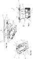
- the Figures 1(a) and 1(b) show an embodiment of a recording unit 3 in an exemplary embodiment, how these are combined with a storage unit 22 can be used to form a storage device 21.
- the receiving unit 3 is designed to receive a product 2, which can in particular be designed as a deposit product, such as a CO2 bottle.
- the receiving unit 3 has a first pivoting device 14, which is mounted, for example, on a frame 15. The mounting takes place, for example, on a drive shaft 16 of an electric motor, wherein the drive shaft 16 simultaneously forms a pivot axis 17 for the pivoting device 14.
- the frame 15 is open on one side, so that the pivoting device 14 projects beyond the frame 15 on the open side. This ensures easier removal or dispensing of the product 2 from or in a combination vending machine, such as in Fig. 15 shown.
- Rollers 10 are arranged on the frame 15, so that the receiving unit 3 can be moved relative to a transport unit 5, as shown for example in Figures 11 to 14 shown, can be moved.
- four rollers 10 can be provided, with one roller 10 each arranged in a corner region of the frame 15.
- the rollers 10 are preferably located on one plane in order to form a plane of movement.
- the receiving unit 3 can be moved automatically by the transport unit 5 at least in the direction of an input opening 4 of the combination machine and/or away from the input opening 4, as in Fig. 15 shown.
- the transport unit 5 has, for example, guide elements 8 in which the rollers 10 can be mounted.
- the guide elements 8 can, for example, be designed as stop elements 9, wherein a vertical displacement of the rollers 10 upwards is prevented by the stop elements 9. A vertical displacement of the rollers 10 downwards is prevented by the transport unit 5, so that guide rails are formed for the rollers 10.
- the guide elements 8 can be formed as L-shaped, bent sheet metal elements made from the material removed from an opening 6.
- the product 2, which is mounted on the pivoting device 14 of the receiving unit 3, can be discharged downwards through the opening 6, for example, in particular into a collecting container or a shaft. This also allows for aligned storage of the products 2.
- An electric motor 18 may be provided outside the frame 15 to drive the drive shaft 16.
- the product 2 may protrude beyond the frame 15 on the open side of the frame 15 so that it can be ergonomically guided to an input opening 4, see Fig. 15 .
- the receiving unit 3 has a guide pin 13 on the underside, which is Figures 11-14 is described in more detail.
- the drive shaft 16 is, in particular, positively connected to the pivoting device 14, so that a movement of the drive shaft 16 is directly converted into a movement of the pivoting device 14.
- the drive can also be provided by a gear, belt, or worm gear, for example.
- a drive with a rack, a cable, hydraulic, or pneumatic drive is also conceivable.
- the products are discharged, in particular upwards, into the storage unit 22.
- the receiving unit 3 can be provided differently from the illustration, in particular without the transport unit 5 and without downward discharge.
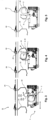
- Fig. 2 shows a possible arrangement of the storage unit 22 above the receiving unit 3.
- the receiving unit 3 is arranged offset to the left of the storage unit 22.
- the receiving unit 3 and the storage unit 22 can be arranged at a different distance from each other, in particular at a different horizontal distance as shown.
- a different distance makes it possible for the product 2 to be transferred from the receiving unit 3 to the storage unit 22, as shown in the Figure 3-5 shown, or from the storage unit 22 to the recording unit 3, as shown in the Figures 6-10 represented, can be transported.
- the receiving unit 3 and the storage unit 22 have mutually corresponding edge regions 26, with the receiving unit 3 having an edge region 26a and the storage unit 22 having an edge region 26b.
- the edge region 26a is arranged in the region of a first pivoting device 14.
- the edge region 26b is arranged on the storage unit 22 opposite the second pivoting device 24.
- the storage unit 22 comprises a second pivoting device 24 about which the storage unit 22 can be pivoted.
- a return element is provided on the second pivoting device 24, so that the storage unit 22 is designed to be self-resetting due to gravity.
- the storage unit 22 is formed from an angled cantilever arm.
- the cantilever arm is designed, in particular, as a U-shaped holding element, so that a product 2 can be held in the storage unit 22.
- Fig. 2 Two storage units 22 are provided, which are arranged on a common guide device 23. Consequently, two products 2 can be temporarily stored.
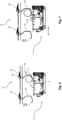
- the Figures 3 to 5 show an embodiment of the storage device 21 when a product 2 is delivered to the storage unit 22, wherein the storage unit 22 and the receiving unit 3 can be seen in cross section.
- the storage unit 22 is shaped as a type of cantilever arm which is mounted on the pivot axis 25.
- the storage unit 22 has, in particular, a U-shaped holding element.
- the U-shaped holding element forms a support surface for the product 2 and, for this purpose, has, in particular, a recess.
- the recess can, for example, be V-shaped so that the product 2 can be prevented from rolling to the right or left when the storage unit 22 is aligned due to gravity.
- the delivery of the product 2 into a storage unit 22 can be carried out as in the Figures 3 to 5 shown.
- the receiving unit 3 is pivoted upwards so that it can be contacted with the storage unit 22. As in Figure 3 As shown, the receiving unit 3 rotates about the first pivoting device 14. In particular, the receiving unit 3 can be pivoted upwards by 90° to 120°, preferably 110°, from the basic position.
- the edge regions 26a, 26b contact each other so that a first inclined plane 27 is formed.
- the first inclined plane 27 has an angle such that the product 2 can roll or slide from the receiving unit 3 into the storage unit 22. If the product 2 is not cylindrical, it can also slide or slide on the inclined plane 27.
- the storage unit 22 can be deflected to the right in the illustration. This allows the desired first inclined plane 27 can be reached in the first position.
- the storage unit 22 aligns itself automatically due to gravity, whereby the product 2 is securely held in the storage unit 22.
- the geometry of the cantilever arm is therefore formed, as shown, from surfaces angled towards one another, which in particular form a U-shaped holding element. Secure deposit is facilitated by the resetting of the storage unit 22 by a resetting element provided on the second pivoting device 24.
- the center of gravity of the storage unit 22 is aligned with respect to a pivot axis 25 in such a way that a resetting to the home positions can be optimized.
- contact surfaces 29a, 29b are provided at the edge regions 26a, 26b so that the storage unit 22 and the receiving unit 3 can be supported against one another.
- the contact surfaces 29a, 29b can be formed as beveled regions of the storage unit 22 or the receiving unit 3. In this case, several contact regions 29a, 29b can be provided at a distance from one another at each edge region 26a, 26b.
- FIGS. 6 to 10 show the dispensing of a product 2 from the storage unit 22 into the dispensing unit 3.
- the receiving unit 3 and the storage unit 22 for removing the product 2 from the combination machine are arranged at a distance, in particular at a horizontal distance, from each other, which does not correspond to the distance as in the Figures 3 to 5 shown.
- the receiving unit 3 and/or the storage unit 22 can be displaced horizontally.
- the receiving unit 3 can be displaced linearly to the right, in particular by 30 mm to 80 mm, preferably by 40 mm to 70 mm, in particular by 60 mm, as shown in Figure 7
- the specified distances are particularly advantageous when the receiving unit 3 is pivoted upwards.
- the receiving unit 3 and the storage unit 22 can be arranged at the same distance from each other as in the Figures 3 to 5 shown.
- a second inclined plane 28 is achieved solely by the angle of rotation in which the receiving unit 3 is pivoted.
- the receiving unit 3 can be pivoted upwards by 70° to 90°, in particular by 80°.
- the pivot angle is smaller than in the process of Figures 3 to 5 .
- the receiving unit 3 can be displaced linearly to the right, in particular by 30 mm to 80 mm, preferably by 40 mm to 70 mm, in particular by 40 mm to 60 mm.
- a second inclined plane 28 can be formed, which has a gradient opposite to that of the first inclined plane 27, as indicated by the dashed line in Figure 9 shown.
- the edge regions 26a, 26b contact each other, so that the storage unit 22 is deflected at a desired angle around the rotation axis 25.
- the product 2 can slide, slide or roll from the storage unit 22 onto the receiving unit 3, depending on the geometry of the product 2.
- the receiving unit 3 can be moved linearly in the opposite direction as previously described, ie to the left in the illustration, as shown in Figure 10 shown. Simultaneously or subsequently, the receiving unit 3 can be pivoted downwards back into its basic position, whereby contact with the storage unit 22 is lost.
- the storage unit 22 can therefore move back into its initial position, in particular by means of a return element on the second pivoting device 24. Once the product 2 is again on the receiving unit 3, it can either be removed from the combination machine by the customer or sorted into corresponding shafts or receiving containers within the combination machine.
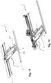
- the Figures 11 to 14 show a possible embodiment of the transport unit 5 of the receiving unit 3 mounted on guide rails 11.
- the illustrated overall system can be referred to as a receiving device 1.
- the guide rails 11 are arranged parallel to each other, whereby the front guide rail in the figures can be arranged closer to an input opening.
- the input opening 4 is, for example, Figure 15 , whereby the position of the guide rails 11 in the combination machine 19 can be clarified.
- the guide rails 11 allow the transport unit 5 to be moved towards the input opening 4 in order to enable the insertion of a product 2 onto the receiving unit 3.
- the transport unit 5 can be moved transversely to the input opening 4 in order to place the product 2 at any desired position inside or outside the machine.
- the directions of travel are indicated by the arrows in Figure 9 and Figure 10 shown.
- the Figures 13 and 14 show a guide contour 12 that can be provided between the two guide rails 11.
- the guide contour 12 can be formed in one piece with a guide rail 11.
- the guide contour 12 can be welded to the guide rail 11 or screwed to it.
- the guide contour 12 is designed as a component that has a side edge that is at least partially partially circular.
- the guide pin 13 can be guided along this side edge, thereby triggering a movement of the receiving unit 3.
- the guide pin 13 is therefore arranged on the receiving unit 3 so that the receiving unit 3 can be moved in the direction of the input opening 4 when the guide pin contacts the guide contour, and the transport unit 5 is moved along the guide rails 11.
- a movement of the transport unit 5 in a first direction of movement can trigger a movement of the receiving unit 3 in a second direction of movement.
- the two directions of movement are particularly directed transversely to each other. This allows the product 2 to be moved toward the input opening 4 on the one hand and at least partially through the input opening 4 on the other. This ensures simple and ergonomic removal and insertion of the product.
- the product 2 projects beyond the guide rail 11 when the transport unit 5 is arranged on a side area on which the guide contour 12 is located.
- Fig. 15 shows an embodiment of the combination machine 19 with a storage device 21.
- the interior of the combination machine 19 is shown in the area of the input opening 4.
- the receiving unit 3 can be seen.
- the receiving unit 3 is located in this illustration, for example, in the position as in Figure 14 shown.
- the product 2 can be moved towards a front side 20 of the combination machine 19, thereby moving it closer to the input opening 4.
- the product 2 can also be moved away from the input opening 4 in order to then be delivered to the storage unit 22 at any desired position within the combination machine 19. This position can also be reached via guide rails 11, along which the transport unit 5 can be moved.
- the combination machine 19 may further comprise a dispensing opening 30 which is provided in addition to the input opening 4.
- the storage unit 22 which is not accessible from the outside, can be provided inside the combination vending machine 19.
- the storage unit 22 enables targeted intermediate storage of the products 2 within the vending machine, particularly when fewer products are removed from the vending machine than are dispensed into it.
- sensors or at least a light barrier can be provided to detect what type of product was inserted into the receiving unit 3.
- the detected product 2 can then be specifically sorted or, if necessary, rejected. For example, an incorrectly inserted product or even waste can be detected, which should therefore not be introduced into the combination machine 19.
- a product that has been incorrectly detected can, for example, be discharged downwards.
- the pivoting device 14 can therefore be used for sorting, whereby a selection of products is discharged upwards and another selection of products downwards through an opening 6 in the receiving device 1, as shown in Fig. 1 shown.
- Individual products 2 can also be disposed of in a waste container, for example.
- the number of storage units 22 can be expanded as desired, whereby the number of temporarily stored products 2 can also be increased.
- the storage unit 22 is particularly suitable for the temporary storage of CO2 cylinders, but can also be used for deposit bottles, glass bottles, PET bottles or general products and containers.
- a drive for example, electrical, pneumatic, or hydraulic, can also be provided for the storage unit 22, so that it can also be operated independently of the receiving unit 3.
- the position of the center of gravity of the storage unit 22 with respect to the rotation axis 25 has a beneficial effect on the self-resetting due to gravity.
- the geometry of the receiving unit 3 and the storage unit 22 is designed such that a transfer can take place barrier-free, reliably and securely during both the depositing process and the removal process.
- different angles of rotation can be implemented, whereby the angles of rotation are not limited to the previously mentioned angular ranges.
- any desired linear displacement of the storage unit 22 relative to the receiving unit 3 can take place.
- the sequence can be varied, whereby the sequence of a displacement and a rotation can be carried out one after the other in any desired sequence. For example, when removing products 2, a movement, i.e. in particular a linear movement, can be omitted and only a pivoting can take place.
- stops in particular mechanical stops, can be provided to limit the angle of rotation of the storage unit 22 and/or the receiving unit 3, in particular in both directions of rotation. This can, in particular, prevent the storage unit 22 from oscillating or swinging upwards.
- this offers the advantage of enabling the collective dispensing of multiple products 2.
- multiple products can be accepted by the combination vending machine without having to dispense a product 2 in between.
- the number of products 2 that can be returned during a collective dispensing is regulated by the number of storage units 22 in the combination vending machine 19.
- items that are not intended to be accepted but have been left in the receiving unit 3 by a customer can also be sorted into the storage device 21.
- a cost-effective implementation of a storage device 21 can be provided that can be implemented with only a few components. Accordingly, integration into existing combination machines 19, such as in particular CO2 combination machines, can be achieved cost-effectively and with few components.
- stepless travel options enable gentle treatment of the products 2, whereby the storage device 21 is also suitable for glass bottles.
Landscapes
- Physics & Mathematics (AREA)
- General Physics & Mathematics (AREA)
- Vending Machines For Individual Products (AREA)
Applications Claiming Priority (1)
| Application Number | Priority Date | Filing Date | Title |
|---|---|---|---|
| DE102023135758.1A DE102023135758A1 (de) | 2023-12-19 | 2023-12-19 | Speichervorrichtung zur Speicherung von Produkten in einem Kombiautomaten, Automat und Verfahren |
Publications (1)
| Publication Number | Publication Date |
|---|---|
| EP4576032A1 true EP4576032A1 (fr) | 2025-06-25 |
Family
ID=93843607
Family Applications (1)
| Application Number | Title | Priority Date | Filing Date |
|---|---|---|---|
| EP24218326.7A Pending EP4576032A1 (fr) | 2023-12-19 | 2024-12-09 | Dispositif de stockage pour stocker des produits dans un distributeur automatique combiné, automate et procédé |
Country Status (2)
| Country | Link |
|---|---|
| EP (1) | EP4576032A1 (fr) |
| DE (1) | DE102023135758A1 (fr) |
Citations (8)
| Publication number | Priority date | Publication date | Assignee | Title |
|---|---|---|---|---|
| DE202006018119U1 (de) * | 2006-11-29 | 2007-02-01 | Loetec Elektronische Fertigungssysteme Gmbh | Annahmeeinrichtung für Rücknahmeautomaten für zumindest nahezu achssymmetrische Rotationskörper |
| EP2107534A1 (fr) * | 2008-04-05 | 2009-10-07 | Wincor Nixdorf International GmbH | Automate de reprise pour bouteilles consignées |
| US20160182861A1 (en) * | 2014-12-17 | 2016-06-23 | Wincor Nixdorf International Gmbh | Reverse vending machine |
| WO2020089425A1 (fr) * | 2018-10-31 | 2020-05-07 | Tomra Systems Asa | Distributeur automatique inverse et procédé de fonctionnement d'un distributeur automatique inverse |
| US20210256792A1 (en) * | 2018-08-29 | 2021-08-19 | Swyft Inc. | Automated store technologies |
| US20220058604A1 (en) * | 2020-08-18 | 2022-02-24 | Dov Z. Glucksman | Autonomous Food Station |
| US20220204280A1 (en) * | 2019-06-12 | 2022-06-30 | Pure Recycle Oy | A conveyor and a method for a beverage container recycler |
| GB2602803A (en) * | 2021-01-13 | 2022-07-20 | Revermatic Ltd | Container lowering system for a reverse vending machine |
-
2023
- 2023-12-19 DE DE102023135758.1A patent/DE102023135758A1/de active Pending
-
2024
- 2024-12-09 EP EP24218326.7A patent/EP4576032A1/fr active Pending
Patent Citations (8)
| Publication number | Priority date | Publication date | Assignee | Title |
|---|---|---|---|---|
| DE202006018119U1 (de) * | 2006-11-29 | 2007-02-01 | Loetec Elektronische Fertigungssysteme Gmbh | Annahmeeinrichtung für Rücknahmeautomaten für zumindest nahezu achssymmetrische Rotationskörper |
| EP2107534A1 (fr) * | 2008-04-05 | 2009-10-07 | Wincor Nixdorf International GmbH | Automate de reprise pour bouteilles consignées |
| US20160182861A1 (en) * | 2014-12-17 | 2016-06-23 | Wincor Nixdorf International Gmbh | Reverse vending machine |
| US20210256792A1 (en) * | 2018-08-29 | 2021-08-19 | Swyft Inc. | Automated store technologies |
| WO2020089425A1 (fr) * | 2018-10-31 | 2020-05-07 | Tomra Systems Asa | Distributeur automatique inverse et procédé de fonctionnement d'un distributeur automatique inverse |
| US20220204280A1 (en) * | 2019-06-12 | 2022-06-30 | Pure Recycle Oy | A conveyor and a method for a beverage container recycler |
| US20220058604A1 (en) * | 2020-08-18 | 2022-02-24 | Dov Z. Glucksman | Autonomous Food Station |
| GB2602803A (en) * | 2021-01-13 | 2022-07-20 | Revermatic Ltd | Container lowering system for a reverse vending machine |
Also Published As
| Publication number | Publication date |
|---|---|
| DE102023135758A1 (de) | 2025-06-26 |
Similar Documents
| Publication | Publication Date | Title |
|---|---|---|
| EP3106241B1 (fr) | Machine-outil et procédé destinés a l'évacuation de parties d'une pièce à usiner | |
| DE112006001872B4 (de) | Kommissionierverfahren sowie Kommissionierfördervorrichtung für ein Lager | |
| EP4126719B1 (fr) | Procédé pour trier des articles et dispositif de tri | |
| EP2353149B1 (fr) | Procédé et installation de transport pour le recyclage d'emballages vides en retour, en particulier de bouteilles et de boîtes | |
| EP2396269B1 (fr) | Dispositif pour remplir des récipients | |
| EP0077554B1 (fr) | Dispositif pour le vidage de réceptacles | |
| EP2125578B1 (fr) | Procédé pour le stockage de marchandises à stocker dans un rayonnage de stockage, comprenant plusieurs unités de rayonnage et un puits de transport, ainsi qu'un tel rayonnage de stockage | |
| EP2855282B1 (fr) | Procédé et appareil pour transférer des articles à partir de stations de distribution vers des stations de réception | |
| AT10979U1 (de) | Sortiervorrichtung | |
| DE69313784T2 (de) | Entladeeinheit einer Fördereinrichtung und Verfahren zum Entladen von der Fördereinrichtung | |
| EP1762511B1 (fr) | Entrepôt automatique avec transstockeur avec gaine tampon et méthode d'opération d'un tel entrepôt | |
| EP0695704A1 (fr) | Dispositif de transport pour articles | |
| DE3808157C2 (de) | Münzen-Stapelvorrichtung | |
| EP4576032A1 (fr) | Dispositif de stockage pour stocker des produits dans un distributeur automatique combiné, automate et procédé | |
| DE102010035670A1 (de) | Hochgeschwindigkeitsspeicher | |
| EP3557541A1 (fr) | Redresseur de bouteilles, dispositif automatique de recyclage et installation de tri | |
| EP2174897B1 (fr) | Dispositif de guidage de bouteilles consignées | |
| WO2007115946A1 (fr) | Unite de transport dans un systeme de recuperation de produits vides | |
| EP4029811A1 (fr) | Bande transporteuse destinée au transport des marchandises à transporter et ligne d'emballage d'une installation d'emballage doté d'une telle bande transporteuse | |
| EP0822739B1 (fr) | Appareil automatisé de test de cartes de circuit électronique | |
| DE2552211A1 (de) | Vorrichtung zum transportieren von gefaessen | |
| AT509952B1 (de) | Verfahren und vorrichtung zum fördern und puffern von gepressten paketen | |
| DE102006049411A1 (de) | Vorrichtung zum Transportieren von Behältern | |
| EP3166736A1 (fr) | Manutention d'emballages vides pour des systèmes de reprise | |
| DE202023102165U1 (de) | Sortiervorrichtung für ein Kommissioniersystem und Kommissioniersystem |
Legal Events
| Date | Code | Title | Description |
|---|---|---|---|
| PUAI | Public reference made under article 153(3) epc to a published international application that has entered the european phase |
Free format text: ORIGINAL CODE: 0009012 |
|
| STAA | Information on the status of an ep patent application or granted ep patent |
Free format text: STATUS: THE APPLICATION HAS BEEN PUBLISHED |
|
| AK | Designated contracting states |
Kind code of ref document: A1 Designated state(s): AL AT BE BG CH CY CZ DE DK EE ES FI FR GB GR HR HU IE IS IT LI LT LU LV MC ME MK MT NL NO PL PT RO RS SE SI SK SM TR |
|
| STAA | Information on the status of an ep patent application or granted ep patent |
Free format text: STATUS: REQUEST FOR EXAMINATION WAS MADE |
|
| 17P | Request for examination filed |
Effective date: 20251203 |
|
| RIC1 | Information provided on ipc code assigned before grant |
Ipc: G07F 7/06 20060101AFI20260205BHEP Ipc: G07F 11/16 20060101ALI20260205BHEP |
|
| GRAP | Despatch of communication of intention to grant a patent |
Free format text: ORIGINAL CODE: EPIDOSNIGR1 |
|
| STAA | Information on the status of an ep patent application or granted ep patent |
Free format text: STATUS: GRANT OF PATENT IS INTENDED |