EP3559554B1 - Appareil de cuisson à gaz - Google Patents
Appareil de cuisson à gaz Download PDFInfo
- Publication number
- EP3559554B1 EP3559554B1 EP17816853.0A EP17816853A EP3559554B1 EP 3559554 B1 EP3559554 B1 EP 3559554B1 EP 17816853 A EP17816853 A EP 17816853A EP 3559554 B1 EP3559554 B1 EP 3559554B1
- Authority
- EP
- European Patent Office
- Prior art keywords
- gas
- burner
- cooking
- cooking appliance
- regulating valve
- Prior art date
- Legal status (The legal status is an assumption and is not a legal conclusion. Google has not performed a legal analysis and makes no representation as to the accuracy of the status listed.)
- Active
Links
Images



Classifications
-
- F—MECHANICAL ENGINEERING; LIGHTING; HEATING; WEAPONS; BLASTING
- F23—COMBUSTION APPARATUS; COMBUSTION PROCESSES
- F23N—REGULATING OR CONTROLLING COMBUSTION
- F23N1/00—Regulating fuel supply
- F23N1/002—Regulating fuel supply using electronic means
-
- F—MECHANICAL ENGINEERING; LIGHTING; HEATING; WEAPONS; BLASTING
- F24—HEATING; RANGES; VENTILATING
- F24C—DOMESTIC STOVES OR RANGES ; DETAILS OF DOMESTIC STOVES OR RANGES, OF GENERAL APPLICATION
- F24C3/00—Stoves or ranges for gaseous fuels
- F24C3/12—Arrangement or mounting of control or safety devices
- F24C3/126—Arrangement or mounting of control or safety devices on ranges
-
- F—MECHANICAL ENGINEERING; LIGHTING; HEATING; WEAPONS; BLASTING
- F23—COMBUSTION APPARATUS; COMBUSTION PROCESSES
- F23N—REGULATING OR CONTROLLING COMBUSTION
- F23N1/00—Regulating fuel supply
- F23N1/005—Regulating fuel supply using electrical or electromechanical means
-
- F—MECHANICAL ENGINEERING; LIGHTING; HEATING; WEAPONS; BLASTING
- F23—COMBUSTION APPARATUS; COMBUSTION PROCESSES
- F23N—REGULATING OR CONTROLLING COMBUSTION
- F23N5/00—Systems for controlling combustion
- F23N5/02—Systems for controlling combustion using devices responsive to thermal changes or to thermal expansion of a medium
- F23N5/10—Systems for controlling combustion using devices responsive to thermal changes or to thermal expansion of a medium using thermocouples
- F23N5/102—Systems for controlling combustion using devices responsive to thermal changes or to thermal expansion of a medium using thermocouples using electronic means
-
- F—MECHANICAL ENGINEERING; LIGHTING; HEATING; WEAPONS; BLASTING
- F23—COMBUSTION APPARATUS; COMBUSTION PROCESSES
- F23N—REGULATING OR CONTROLLING COMBUSTION
- F23N5/00—Systems for controlling combustion
- F23N5/02—Systems for controlling combustion using devices responsive to thermal changes or to thermal expansion of a medium
- F23N5/10—Systems for controlling combustion using devices responsive to thermal changes or to thermal expansion of a medium using thermocouples
- F23N5/105—Systems for controlling combustion using devices responsive to thermal changes or to thermal expansion of a medium using thermocouples using electrical or electromechanical means
-
- F—MECHANICAL ENGINEERING; LIGHTING; HEATING; WEAPONS; BLASTING
- F23—COMBUSTION APPARATUS; COMBUSTION PROCESSES
- F23N—REGULATING OR CONTROLLING COMBUSTION
- F23N5/00—Systems for controlling combustion
- F23N5/20—Systems for controlling combustion with a time program acting through electrical means, e.g. using time-delay relays
- F23N5/203—Systems for controlling combustion with a time program acting through electrical means, e.g. using time-delay relays using electronic means
-
- F—MECHANICAL ENGINEERING; LIGHTING; HEATING; WEAPONS; BLASTING
- F24—HEATING; RANGES; VENTILATING
- F24C—DOMESTIC STOVES OR RANGES ; DETAILS OF DOMESTIC STOVES OR RANGES, OF GENERAL APPLICATION
- F24C3/00—Stoves or ranges for gaseous fuels
- F24C3/12—Arrangement or mounting of control or safety devices
-
- F—MECHANICAL ENGINEERING; LIGHTING; HEATING; WEAPONS; BLASTING
- F23—COMBUSTION APPARATUS; COMBUSTION PROCESSES
- F23N—REGULATING OR CONTROLLING COMBUSTION
- F23N2223/00—Signal processing; Details thereof
- F23N2223/38—Remote control
-
- F—MECHANICAL ENGINEERING; LIGHTING; HEATING; WEAPONS; BLASTING
- F23—COMBUSTION APPARATUS; COMBUSTION PROCESSES
- F23N—REGULATING OR CONTROLLING COMBUSTION
- F23N2225/00—Measuring
- F23N2225/08—Measuring temperature
-
- F—MECHANICAL ENGINEERING; LIGHTING; HEATING; WEAPONS; BLASTING
- F23—COMBUSTION APPARATUS; COMBUSTION PROCESSES
- F23N—REGULATING OR CONTROLLING COMBUSTION
- F23N2235/00—Valves, nozzles or pumps
- F23N2235/12—Fuel valves
- F23N2235/16—Fuel valves variable flow or proportional valves
-
- F—MECHANICAL ENGINEERING; LIGHTING; HEATING; WEAPONS; BLASTING
- F23—COMBUSTION APPARATUS; COMBUSTION PROCESSES
- F23N—REGULATING OR CONTROLLING COMBUSTION
- F23N2237/00—Controlling
- F23N2237/02—Controlling two or more burners
-
- F—MECHANICAL ENGINEERING; LIGHTING; HEATING; WEAPONS; BLASTING
- F23—COMBUSTION APPARATUS; COMBUSTION PROCESSES
- F23N—REGULATING OR CONTROLLING COMBUSTION
- F23N2241/00—Applications
- F23N2241/08—Household apparatus
Definitions
- the present invention relates to gas cooking appliances.
- Gas cooking appliances are known to comprise a gas line feeding at least one manual gas flow regulating valve, which can be a gas cock, and at least one gas burner fed by a gas flow regulated by the regulating valve.
- a manual gas flow regulating valve which can be a gas cock
- a gas burner fed by a gas flow regulated by the regulating valve.
- EP2789280A1 discloses a gas cooking appliance in which each manual regulating valve is in direct fluid communication with its respective gas burner.
- the gas cooking appliance further comprises one main cut-off valve between the gas supply and the gas line feeding the manual regulating valves, a control unit for controlling the cut-off valve and a manual actuator.
- the manual actuator comprises a first position allowing the passage of gas through the cut-off valve, and a second position allowing the user to control the operation of the gas cooking appliance remotely by means of a remote control unit, activating the control unit and putting said control unit in contact with the remote control unit by means of exchanging instructions.
- the user can remotely close the cut-off valve for turning the gas cooking appliance off.
- the manual actuator After closing the cut-off valve, it is necessary to move the manual actuator back to the first position in order to open the cut-off valve and turn the gas cooking appliance on again. After turning on the gas cooking appliance, the manual actuator has to be moved to the second position for activating the control unit.
- the gas cooking appliances comprise thermal safety elements connected to the control unit, detecting the temperature of the vessel and/or the cooked product.
- these gas cooking appliances usually comprise an electromagnetic valve fluidically arranged between the regulating valve and the gas burner.
- KR2015099080A describes a gas cooking appliance comprising at least one gas burner, a regulating valve for each gas burner for regulating the gas flow reaching the burner from a gas line, said regulating valve comprising an actuator movable in a range of actuation, the gas flow rate being changed when the manual actuator is moved in the range of actuation, an ON-OFF type electromagnetic gas valve fluidically communicating the regulating valve and the burner, a control unit for controlling the electromagnetic valve, and a temperature sensor electrically connected to the control unit to measure a temperature related to a cooking process in the burner.
- the gas cooking appliance protects the vessel and/or cooked product from excessive temperatures.
- US3297252A discloses a gas oven with a mode selecting control knob which permits the selection of a cooking mode and a control knob for selecting a cooking temperature.
- WO2009040243A2 discloses a gas cooktop comprising a gas burner, a manual regulating valve for regulating the gas flow reaching the burner, said regulating valve comprising a manual actuator movable in a range of actuation, the gas flow rate being changed through the regulating valve when the manual actuator is moved in the range of actuation.
- the gas cooktop also comprises an ON-OFF type electromagnetic gas valve fluidically communicating the regulating valve and the burner, a control unit controlling the electromagnetic valve when the cooktop operates in a temperature regulation operating mode, and a temperature sensor electrically connected to the control unit to measure a temperature related to a cooking process in the burner.
- the cooktop is configured to operate in a manual operating mode or in the temperature regulation operating mode. The user must select in which of the modes wants to operate, for example pressing an ON/OFF switch.
- the manual actuator of the gas valve can be used as temperature selector once the temperature regulation operating mode is selected.
- the object of the invention is to provide a gas cooking appliance, as defined in the claims.
- the gas cooking appliance of the invention comprises at least one gas burner, a manual regulating valve for each gas burner for regulating the gas flow reaching the burner from a gas line, said regulating valve comprising a manual actuator movable in a range of actuation, the gas flow rate being changed through the regulating valve when the actuator is moved in the range of actuation, an ON-OFF type electromagnetic gas valve fluidically communicating the regulating valve and the burner, a control unit for controlling the electromagnetic valve, and a temperature sensor electrically connected to the control unit to measure a temperature related to a cooking process in the burner.
- the gas cooking appliance comprises a cooking program selector which is electrically connected to the control unit and mechanically coupled to the actuator, such that when the actuator is moved in the range of actuation, each selected cooking program is associated with a specific gas flow rate supplied by the regulating valve.
- the program selector comprises:
- Gas cooking appliances of the prior art allow regulating the temperature of cooking processes only for a specific gas flow rate supplied by the regulating valve.
- the gas cooking appliance described in KR2015099080A cuts off gas flow when a specific temperature is reached for safety purposes and can even regulate the cooking temperature at high temperatures with a high gas flow to the gas burner, but a cooking program in any range of gas flow rate supplied by the regulating valve cannot be selected.
- the gas cooking appliance of the invention allows selecting a cooking program for different gas flow rates supplied by the regulating valve, such that said regulating valve can be designed to supply the desired gas flow rate to the gas burner at any point of the range of actuation of the actuator, and a cooking program with temperature regulation can be defined at any point of said range of actuation since the program selector which allows doing it is electrically connected to the control unit, the cooking program with temperature regulation being synchronized with a desired gas flow rate for said cooking program.
- Figure 1 shows a general outline of an embodiment of a gas cooking appliance 200 according to the invention which, in this case, is a gas cooker but can be any other gas cooking appliance.
- Figure 2 shows a general outline of a second embodiment of a gas cooking appliance 200 according to the invention.
- Figure 3 shows a partial outline of a regulating valve 20 of the gas cooking appliance 200 of Figure 1 with a program selector 70 coupled thereto, and a regulator element 21 comprising a regulating channel 22 of a gas burner 10, and a pilot channel 26 of a pilot burner 11 of the gas cooking appliance 200.
- Figure 4 shows a plan view of the regulator element 21 of the regulating valve 20 of Figure 3 .
- Figure 8 shows a vessel 110 used for cooking arranged on the gas burner 10 with the flame on, with a product 120 to be cooked therein, with a temperature sensor 60 arranged in contact with the vessel 110 and another temperature sensor 60 arranged in contact with the product 120 to be cooked.
- the first embodiment of the gas appliance 200 of the invention shown in Figure 1 comprises a gas burner 10 that has been turned on and has a flame, with a vessel 110 used for cooking on top.
- the gas cooking appliance 200 also comprises a gas valve 20 for said burner 10.
- the gas valve 20 is fluidically communicated with a gas inlet line 30 feeding said gas valve 20 in an inlet 23 and comprises a gas outlet 24 fluidically connected with the gas burner 10 which allows feeding gas thereto.
- the gas valve 20 comprises a manual actuator 40 which is suitable for acting on the regulating valve 20 for regulating gas flow to the gas burner 10.
- the gas valve 20 comprises a regulator element 21 arranged in the gas flow going through said regulating valve 20, in the interior thereof, in a cavity of the body of the regulating valve 20.
- the manual actuator 40 is mechanically coupled to said regulator element 21.
- the regulator element 21 has a frustoconical shape and can turn about its shaft when it is actuated by the manual actuator 40.
- the manual actuator 40, and therefore the regulator element 21, can turn a maximum angle of rotation A 0 .
- the regulator element 21 therefore moves angularly when it is actuated by the manual actuator 40 within the maximum angle of rotation Ao, which in this embodiment is 270°, between an initial OFF position corresponding to an angular position of 0°, in which the regulating valve 20 is closed and does not supply any gas flow to the burner 10, and a final position D corresponding to an angular position of 270°, in which the regulating valve 20 supplies a maximum flow in this embodiment.
- the regulator element 21 comprises in this embodiment a regulating channel 22 communicating the inlet 23 and the outlet 24 of the regulating valve 20 when the regulator element 21 is turned by the manual actuator 40 to specific angular positions.
- the regulator element 21 comprises a body with a hollow interior, the inlet 23 of the regulating valve 20 being communicated with said hollow interior and the regulating channel 22 fluidically communicating the hollow interior of the body of the regulator element 21 with the outside of said body.
- the regulating channel 22 is aligned with the outlet 24 of the regulating valve 20 in a specific angular position, and fluid communication takes place between the inlet 23 and the outlet 24 of the regulating valve 20.
- the range of angular positions in which gas is supplied to the outlet 24 is referred to as range of actuation, and in this embodiment of the gas cooking appliance 200 it is an angle of rotation A.
- This angle of rotation A is smaller than the maximum angle of rotation A 0 of the regulator element 21.
- gas flow supply to the outlet 24 starts in an angular position A 1 corresponding to a maximum gas flow Q Max , the position A 1 being 90°.
- the manual actuator 40 is turned further, the gas flow progressively decreases to an intermediate gas flow rate, until an angular path A 2 corresponding to a minimum gas flow Q Min , the angular path A 2 being between 180° and 220°, for example.
- the regulator element can be turned further up to 270°, starting at the end of the angular path A 2 with a rapid increase of gas flow to the maximum gas flow Q Max and maintaining it until the final position D.
- the description of the regulator element 21 of the regulating valve 20 is logically a mere embodiment.
- the regulating channel 22 can be designed in any shape such that the gas flow rate supplied to the gas burner 10 in each position of the range of actuation A can be different from one regulating valve 20 to another.
- the regulator element 21 does not have to have a frustoconical shape, nor does it have to be rotary.
- the regulator element 21 can have a shape such that gas flow to the burner 10 is regulated by sliding and not by turning, and the manual actuator 40 acts on the regulating valve 20 in a range of actuation A which is a distance and not an angle.
- the embodiment of the gas cooking appliance 200 that is shown comprises a pilot burner 11 which is arranged close to the gas burner 10.
- the regulating valve 20 supplies a gas flow to the pilot burner 11.
- the gas cooking appliance 200 comprises in this embodiment a gas line 25 fluidically connecting said regulating valve 20 and the pilot burner 11.
- the regulator element 21 also comprises in this embodiment a pilot channel 26 which, like the regulating channel 22, communicates with the hollow interior of the regulator element 21.
- the range of actuation in which gas is supplied to the pilot burner 11 is the same range of actuation A as that of the regulator element 21, gas being supplied from the angular position A 1 until the final position D, such that the inlet 23 of the regulating valve 20 is in fluid communication with the gas line 25 in the range of actuation A.
- said pilot channel 26 has a shape such that gas supply to the pilot burner 11 is constant.
- the gas cooking appliance 200 also comprises an electromagnetic valve 50.
- This electromagnetic valve 50 is an ON-OFF type gas valve, i.e., it has a gas inlet line and a gas outlet line communicated through a gas passage and a closure member (not shown in the drawings), such that by means of electrical signals said closure member is either in an OFF position, closing the gas passage, or in an ON position, leaving the gas passage open.
- the electromagnetic valve 50 is a normally open solenoid-type valve, i.e., the closure member transitions from the ON position to the OFF position when the electromagnetic valve 50 receives an electrical signal, and said electrical signal is maintained.
- the closure member transitions to the ON position with the gas passage open and remains in this position at all times. This allows being able to manually operate said appliance by acting on the regulating valve 20 if the gas cooking appliance 200 is left without electric power.
- Other types of electromagnetic valves 50 can also be used, such as for example a normally closed solenoid-type valve, or a bistable-type valve the closure member of which transitions from the ON position to the OFF position or vice versa by means of electrical pulses, without having to maintain the electrical signal.
- the electromagnetic valve 50 is arranged between the regulating valve 20 and the gas burner 10, allowing their fluid communication.
- the gas cooking appliance 200 comprises a control unit 100, said control unit 100 electrically controlling the electromagnetic valve 50 by sending electrical signals for transitioning said valve from the ON position to the OFF position and keeping it in said position. Furthermore, the gas cooking appliance 200 also comprises a temperature sensor 60 arranged in contact with the vessel 110, specifically in contact with the outer lower base of the vessel 110 which is arranged on the burner 10 that is turned on. In other embodiments of the gas cooking appliance 200, said gas cooking appliance 200 comprises, as shown in Figure 8 , a temperature sensor 60 arranged in contact with the vessel 110, specifically in contact with the lid of the vessel 110, and another temperature sensor 60 arranged in contact with the product 120 to be cooked.
- Each of the temperature sensors 60 is electrically connected to the control unit 100, such that said sensors send electrical signals to the control unit 100 associated with the temperatures that are being sensed during the established cooking process.
- These temperature sensors 60 can be of different types, with them normally being thermistors.
- the temperature sensor 60 arranged in the lid of the vessel 110 is a sensor with Bluetooth LE (Bluetooth Low Energy) technology which in this example senses the temperature in the lid and send the signals indicating the temperature to the control unit 100 by Bluetooth.
- the temperature sensor 60 which is in contact with the product 120 to be cooked is a probe which is placed in contact with said product 120, and sends the signals indicating the sensed temperature to the control unit 100 by means of a wire or wirelessly.
- the gas cooking appliance 200 comprises a cooking program selector 70.
- This program selector 70 is electrically connected to the control unit 100 and mechanically coupled to the manual actuator 40.
- the mechanical coupling takes place between the program selector 70 and a shaft 41 comprised in the manual actuator 40, said shaft 41 in turn being coupled to the regulator element 21 such that the actuation of the manual actuator 40 in its range of actuation A results in an actuation of the regulator element 21 of the regulating valve 20 and of the program selector 70. Therefore, in this embodiment of the gas appliance 200, turning the manual actuator 40 results into turning the regulator element 21 and into turning at least one component of the program selector 70.
- the program selector 70 basically comprises a box-shaped housing (not shown in the drawings) and a rotary element therein mechanically coupled to the shaft 41 of the manual actuator 40 with a conductive end, and a board with different electric circuits, by way of tracks, electrically connected with the control unit 100, said electric circuits corresponding to different cooking programs defined in the gas cooking appliance 200, these cooking programs being temperature-regulated programs. Therefore, when the shaft 41 turns, the rotary element turns, and the conductive end electrically contacts one of the circuits of the board of the program selector 70. Therefore, depending on how the board with electric circuits of the program selector 70 is designed, the conductive end will electrically contact one of said circuits, electrical signals which will be sent to the control unit 100 being generated.
- the board of the program selector 70 is designed such that the electric circuits are arranged within the range of actuation A of the manual actuator 40. Therefore, when acting on the manual actuator 40, electrical connection between the conductive end of the rotary element and one of the electric circuits of the board of the program selector 70 is made within the range of actuation A, said electrical connection coinciding with an angular position in said range of actuation A, the selected cooking program being synchronized with a specific gas flow rate supplied by the regulating valve 20 to the electromagnetic valve 50.
- the control unit when the control unit sends an electrical closing signal at the OFF position to the electromagnetic valve 50, there is no gas flow from the regulating valve 20 to the gas burner 10.
- the electromagnetic valve 50 does not comprise a bypass or gas pathway communicating the regulating valve 20 with the burner 10. This therefore allows the burner 10 to have the flame off and the temperature in the vessel 110 and/or in the product 120 to be cooked to drop.
- the gas cooking appliance 200 of this embodiment comprises the pilot burner 11 which the user turns on when they start to operate said gas cooking appliance 200.
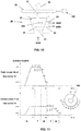
- Figure 5 shows a diagram linking the power of the gas burner 10 and the pilot burner 11 of the gas cooking appliance 200 of Figure 1 with the maximum angle of rotation A 0 of 270° of the regulator element 21 of the regulating valve 20, and it shows visual indicators 140 indicating to the user the cooking programs N, T they can select with the program selector 70.
- Figure 6 shows a diagram linking the power of the gas burner 10 and the pilot burner 11 of the gas cooking appliance 200 of Figure 1 with the maximum angle of rotation A 0 of 270° of the regulator element 21 in a second embodiment of the regulator element 21 of the regulating valve 20, and it shows visual indicators 140 indicating to the user the cooking programs N, T they can select with the program selector 70 in this second embodiment.
- the program selector 70 comprises cooking programs N without temperature regulation which can be selected by the user with the help of the visual indicators 140 arranged in the manual actuator 40 in this embodiment of the gas cooking appliance 200. These cooking programs N correspond with angular positions of the program selector 70, in the angle of rotation A, and therefore with angular positions of the board comprising the different circuits that do not correspond with the position of circuits corresponding to cooking programs T with temperature regulation. These angular positions of cooking programs N correspond to specific gas flow rates supplied by the regulating valve 20 through its regulator element 21.
- control unit 100 is not electrically connected with the electromagnetic valve 50, and therefore does not control it, such that said electromagnetic valve 50 is open and gas flow to the burner 10 is what corresponds to that position of the selected cooking program N, and therefore to the corresponding position of the regulator element 21.
- the program selector 70 also comprises cooking programs T with temperature regulation which can be selected by the user with the help of the visual indicators 140. These cooking programs T correspond with angular positions of the program selector 70, in the angle of rotation A, and therefore with angular positions of the board comprising the different circuits corresponding with the position of circuits corresponding to cooking programs T with temperature regulation. These angular positions of the cooking programs T correspond with specific gas flow rates supplied by the regulating valve 20 through its regulator element 21. In these cooking programs T, the control unit 100 is electrically connected with the electromagnetic valve 50, and therefore controls it.
- the control unit 100 will send electrical signals to the electromagnetic valve 50 for the closure thereof, or it will stop sending the electrical signal for the opening thereof. Therefore, the gas burner 10 may or may not receive a gas flow rate corresponding to the angular position of the selected cooking program T, and therefore to the corresponding position of the regulator element 21.
- the program selector 70 comprises six cooking programs without temperature regulation N 1 -N 6 which are arranged angularly in positions with intermediate gas flow in the regulating channel 22 of the regulator element 21. Then, in the turning direction of the regulator element 21, the program selector 70 comprises six cooking programs with temperature regulation T 1 -T 6 .
- the first three cooking programs T 1 -T 3 are arranged angularly in positions with minimum gas flow Q Min in the regulating channel 22 of the regulator element 21 and correspond with respective regulating temperatures of 60°C, 70°C and 80°C, these temperatures being used, for example, for melting chocolate or heating sauces or ready-made foods at 60°C, for foie gras confits or cod confits at 70°C, and for preparing sauces or sterilizing milk or vegetables at 80°C.
- the other three cooking programs T 4 -T 6 are arranged angularly in positions with maximum gas flow Q Max and correspond with respective regulating temperatures of 100°C, 150°C, and 180°C, these temperatures being used, for example, for rice or pasta at 100°C, for fried fish or battered foods at 150°C, and for french fries or tempuras at 180°C. Therefore, the gas flow rates correspond with the temperature level required by the corresponding cooking program T.
- the program selector 70 comprises six cooking programs without temperature regulation N 1 -N 6 which are arranged angularly in positions with intermediate gas flow in the regulating channel 22 of the regulator element 21.
- the program selector 70 comprises six cooking programs with temperature regulation T 1 -T 6 which are arranged in the following manner: (i) three of the programs arranged angularly in positions with maximum gas flow Q Max before cooking programs N 1 -N 6 in the regulating channel 22 of the regulator element 21, corresponding to cooking programs T 1 -T 3 with respective regulating temperatures of 180°C, 150°C, and 100°C; and (ii) the other three programs arranged angularly in positions with minimum gas flow Q Min corresponding to cooking programs T 4 -T 6 with respective regulating temperatures of 80°C, 70°C and 60°C. Therefore, the gas flow rates correspond with the temperature level
- Figure 7a shows a diagram linking the temperature T obtained at a point of the vessel 110 arranged on the burner 10 or in the cooked product 120, depending on the time t elapsed after turning on the flame in the gas burner 10.
- Figure 7b shows a diagram linking the open or closed state of the electromagnetic valve 50 fluidically communicating the regulating valve 20 and the gas burner 10 with the time t elapsed after turning on the flame in the gas burner 10.
- Figure 7c shows a diagram linking the evolution of the heat power of the gas burner 10 and the pilot burner 11 of the gas cooking appliance 200 of Figure 1 with respect to the time t elapsed after turning on the flame in the gas burner 10 in a cooking program with temperature regulation T 5 .
- Figure 7d shows a diagram linking the evolution of the heat power of the gas burner 10 and the pilot burner 11 of the gas cooking appliance 200 of Figure 1 with respect to the time t elapsed after turning on the flame in the gas burner 10 in a second cooking program with temperature regulation T 2 .
- the gas flow rate in the regulator element 21 corresponds with a maximum gas flow rate Q Max .
- the regulating valve 20 allows the passage of gas to the electromagnetic valve 50, and since cooking program T 5 is selected, an electrical signal reaches the control unit 100 which in turn keeps the electromagnetic valve 50 open. The gas therefore reaches the pilot burner 11 through the gas line 25 and the burner 10 through the outlet 24 of the regulating valve 20. The flame in the pilot burner 11, and accordingly the flame in the gas burner 10, is turned on.
- the pilot burner 11 has a heat power of 80 constant watts since the pilot channel 26 keeps a constant gas flow as a result of its shape.
- the gas burner 10 has a variable heat power since the regulating channel 22 has a shape such that it allows a variable gas flow depending on the angular position within the angle of rotation A. In the angular positions with minimum gas flow Q Min , the heat power of the burner 10 is 600 watts, and in the angular positions with maximum gas flow Q Max , the heat power of the burner 10 is 3,000 watts.
- the temperature sensed by the temperature sensor 60 of the vessel 110 will increase progressively until reaching the temperature level defined in cooking program T 5 , which is 150°C.
- the control unit 100 sends a signal to the electromagnetic valve 50, which thereby closes. Since there is no flame in the burner 10 and since the vessel 110 is only heated by the pilot burner 11 supplying a low heat power of 80 watts, the vessel 110 cools down. When the temperature reaches a lower threshold level for said temperature in the control unit 100, the control unit 100 stops sending the signal to the electromagnetic valve 50, which thereby opens. The burner 10 already receiving a gas flow turns on with the flame of the pilot burner 11, and the vessel 110 heats up. Progressively over time and while the time of cooking program T 5 lasts, the temperature will gradually be regulated.
- the gas passage in the electromagnetic valve 50 is initially open and there is gas flow to the gas burner 10. Every time the temperature reaches the upper threshold level, the gas passage in the electromagnetic valve 50 closes and there is no gas flow to the gas burner 10. Every time the temperature reaches the lower threshold level, the gas passage in the electromagnetic valve 50 opens and there is gas flow to the gas burner 10.
- the heat power corresponds to the sum of the heat powers of the burner 10, corresponding to 3,000 watts in this cooking program, and of the pilot burner 11, corresponding to 80 watts in this cooking program.
- the gas passage closes, and only the heat power of the pilot burner 11 exists.
- the gas passage opens, and the heat power of the burner 10 is again added to the heat power of the pilot burner 11, and so on and so forth as long as cooking program T 5 is underway.
- a cooking program with temperature regulation T 2 corresponding with a regulating temperature of 70°C is defined, for example, the gas flow rate in the regulator element 21 corresponds with a minimum gas flow rate Q Min .
- the regulation of the temperature overtime, and the evolution of the state of the electromagnetic valve 50 over time behave similarly as in cooking program T 5 , with the only difference being that for said selected temperature of 70°C it will correspond with upper and lower threshold levels corresponding to said temperature which will be defined in the control unit 100.
- the heat power of the pilot burner 11 is so low, i.e., 80 watts, it does not interfere with the regulation of low temperatures, as is the case in cooking program T 2 with a selected temperature of 70°C, since the vessel 110 is only heated with the flame of the pilot burner 11 at those times.
- the gas cooking appliance 200 also comprises a thermocouple 80 arranged close to the burner 10, and specifically close to the pilot burner 11, said thermocouple 80 being electrically connected to an electromagnetic valve of the regulating valve 20 (not shown in the drawings).
- This thermocouple 80 has a safety function because, as a result of the flame of the pilot burner 11, being ON at all times, the electromagnetic valve of the regulating valve 20 is open and the gas flow, where appropriate, is conducted to the electromagnetic valve 50. However, if for any reason the flame in the pilot burner 11 goes out, the electromagnetic valve of the regulating valve 20 closes, the gas flow to the electromagnetic valve 50 being closed.
- the gas cooking appliance 200 also comprises a spark igniter 90 arranged close to the burner 10.
- This spark igniter 90 is electrically connected to the control unit 100, and its function is an alternative to the function of the pilot burner 11, the control unit 100 being what sends ON signals to the spark igniter 90. Since the spark igniter 90 does not generate any heat power, it will not affect cooking programs T with low temperatures either, these programs being those running the greatest risk of temperatures not being regulated. However, every time the electromagnetic valve 50 closes and the burner 10 is turned off, said burner 10 is turned on again with the spark igniter 90.
- the control unit 100 is activated when the manual actuator 40 moves, since it activates an electric switch (not shown in the drawings).
- the gas cooking appliance 200 also comprises a remote control unit 150, the connection between the control unit 100 and the remote control unit 150 being activated when the manual actuator 40 moves axially.
- the remote control unit 150 allows monitoring and controlling the gas cooking appliance 200, the connection with the control unit 100 being able to be wired or wireless.
- the remote control unit 150 can be a smart mobile telephone or a tablet.
- the control unit 100 comprises visual and acoustic warning means 130, said warning means 130 alerting the user when one of the temperature sensors 60 does not detect the temperature defined by the cooking program with temperature regulation T selected with the program selector 70.
- This may be the case of providing a vessel 110 that is too large for the selected burner 10 or putting too much product 120 to be cooked in the vessel 110.
- the operativity of this appliance is the same as that described above for the first embodiment of the gas cooking appliance 200.
- the burner 10 of this second embodiment comprises two crowns, a central crown 10a and an outer crown 10b. Gas from a different inlet feeds each of the crowns of the burner 10.
- Each of these inlets to the crowns 10a, 10b of the burner 10 are fluidically communicated with a corresponding electromagnetic valve 50a, 50.
- these electromagnetic valves 50a, 50 are fluidically communicated with a corresponding outlet 24a, 24b of the regulating valve 20.
- the regulating valve 20 of this second embodiment of the gas cooking appliance 200 comprises a regulator element with two parallel regulating channels (not shown in the drawings) with the same range of actuation.
- a third embodiment of the gas cooking appliance 200 shown in Figure 9 , the operativity of this appliance is the same as that described above for the second embodiment of the gas cooking appliance 200.
- the pilot burner has been removed and the electromagnetic valve fluidically communicating the regulating valve 20 with the central crown 10a is a restrictor type electromagnetic valve 51, instead of being an ON-OFF electromagnetic valve.
- a restrictor type electromagnetic valve comprises a "closed" position that, instead of totally avoiding the flow of gas, provides a minimum flow of gas, said minimum flow being enough for keeping the flame ON. Therefore, the restrictor type electromagnetic gas valve 51 comprises a first position in which a maximum flow is provided and a second position in which a minimum flow is provided.
- the central crown 10a can act as a pilot burner and a pilot burner is not necessary.
- the thermocouple 80 is close to the central crown 10a.
- the regulating valve 20 comprises, as shown in Figure 10 , a regulator element 21 with two parallel corresponding channels, a pilot channel 26, and a regulating channel 22b, which in this embodiment have different ranges of actuation.
- gas flow supply from the pilot channel 26 to the gas line 25 starts in an angular position corresponding to a maximum gas flow Q Max , the position being 90°.
- the gas flow progressively decreases to an intermediate gas flow rate, until a final position being between 225° and 270°, for example.
- the manual actuator 40 is turned further, the gas flow progressively decreases to an intermediate gas flow rate, until a final position being 190°, for example.
- Figure 11 shows a diagram linking the power of the central crown 10a and the outer crown 10b of the gas burner 10 of the gas cooking appliance 200 of Figure 9 , with the angle of rotation of the regulator element 21, in one embodiment of the regulator element 21 of the regulating valve 20, and it shows visual indicators 140 indicating to the user the cooking programs they can select with the program selector 70.
- the program selector 70 comprises six cooking programs without temperature regulation N 1 -N 6 which are arranged angularly in positions, between 145° to 185°, with maximum gas flow, N 1 -N 3 , in the low-power channel 26 of the regulator element 21, and in positions, between 230° to 270°, with intermediate gas flow, N 4 -N 6 , in the low-power channel 26 of the regulator element 21.
- the program selector 70 also comprises six cooking programs with temperature regulation T 1 -T 6 .
- the first three cooking programs T 1 -T 3 are arranged angularly in positions between 100° to 145°, with maximum gas flow in the regulating channel 22b of the regulator element 21, and correspond with respective regulating temperatures of 180°C, 150°C and 100°C
- the other three cooking programs T 4 -T 6 are arranged angularly in positions between 185° to 230°, with maximum gas flow in the low-power channel 26, and correspond with respective regulating temperatures of 80°C, 70°C, and 60°C, the gas flow rates correspond with the temperature level required by the corresponding cooking program T.
- Figure 12 shows a preferred embodiment of the program selector 70 of the gas cooking appliance 200 of the invention.
- the program selector 70 comprises lighting means 75 that inform the user about the state of the gas cooking appliance 200 depending on the color and/or intensity and/or the frequency of the light emitted by said lighting means 75.
- the lighting means 75 comprise at least one led (three in the embodiment shown in Figure 12 ) and a light guide (not shown in Figure 12 ) that delimits the contour of the manual actuator 70.
- Figure 12 further shows the rotary element 71 mechanically coupled to the shaft 41 of the manual actuator 40 with a conductive end, and the board 72 with different electric circuits 73, by way of tracks, electrically connected with the control unit 100.
Landscapes
- Engineering & Computer Science (AREA)
- Chemical & Material Sciences (AREA)
- Combustion & Propulsion (AREA)
- Mechanical Engineering (AREA)
- General Engineering & Computer Science (AREA)
- Feeding And Controlling Fuel (AREA)
Claims (15)
- Appareil de cuisson à gaz comprenant au moins un brûleur à gaz (10), une vanne de régulation manuelle (20) pour chaque brûleur à gaz (10) pour réguler le débit de gaz atteignant le brûleur (10) depuis une conduite de gaz (30), ladite vanne de régulation (20) comprenant un actionneur manuel (40) mobile dans une plage d'actionnement (A), le débit de gaz (Q) étant modifié par la vanne de régulation (20) lorsque l'actionneur manuel (40) est déplacé dans la plage d'actionnement (A), au moins une vanne de gaz électromagnétique de type ON-OFF (50) faisant communiquer fluidiquement la vanne de régulation (20) et le brûleur (10), une unité de commande (100) commandant la soupape électromagnétique (50), au moins un capteur de température (60) relié électriquement à l'unité de commande (100) pour mesurer une température liée à un processus de cuisson dans le brûleur (10), et un sélecteur de programme de cuisson (70) relié électriquement à l'unité de commande (100) et couplé mécaniquement à l'actionneur (40), de sorte que lorsque l'actionneur (40) est déplacé dans la plage d'actionnement (A), chaque programme de cuisson sélectionné est associé à un débit de gaz spécifique (Q) fourni par la vanne de régulation (20), caractérisé en ce que le sélecteur de programme (70) comprend des programmes de cuisson (N) sans régulation de température qui peuvent être sélectionnés par l'utilisateur à l'aide d'indicateurs visuels (140), ces programmes de cuisson (N) correspondant à une pluralité de premières positions angulaires du sélecteur de programme (70) dans la plage d'actionnement (A), lesdites premières positions angulaires des programmes de cuisson (N) correspondant à des débits de gaz spécifiques fournis par la vanne de régulation (20), et des programmes de cuisson (T) avec régulation de température pour effectuer le processus de cuisson correspondant, qui peuvent être sélectionnés par l'utilisateur à l'aide des indicateurs visuels (140), ces programmes de cuisson (T) correspondant à une pluralité de secondes positions angulaires du sélecteur de programme (70) dans la plage d'actionnement (A), lesdites secondes positions angulaires des programmes de cuisson (T) correspondant à des débits de gaz spécifiques fournis par la soupape de régulation (20), l'unité de commande (100) agissant sur la vanne électromagnétique (50) en fonction du programme de cuisson (T) sélectionné avec régulation de la température.
- Appareil de cuisson à gaz selon la revendication 1, dans lequel, lorsque la vanne électromagnétique (50) est fermée, il n'y a pas de débit de gaz entre la vanne de régulation (20) et le brûleur respectif (10).
- Appareil de cuisson à gaz selon la revendication 1 ou 2, dans lequel le sélecteur de programme (70) comprend au moins un programme de cuisson avec régulation de la température (T) dans au moins une section avec un débit de gaz minimum (Qmin) fourni par la vanne de régulation (20) dans la plage d'actionnement (A).
- Appareil de cuisson à gaz selon l'une des revendications 1 à 3, dans lequel le sélecteur de programme (70) comprend au moins un programme de cuisson avec une régulation de température (T) dans au moins une section avec un débit de gaz maximum (QMax) fourni par la vanne de régulation (20) dans la plage d'actionnement (A).
- Appareil de cuisson au gaz selon l'une des revendications précédentes, dans lequel la vanne de régulation (20) comprend un élément régulateur (21) couplé à l'actionneur (40), l'élément régulateur (21) comprenant au moins un canal de régulation (22) adapté pour réguler le débit de gaz entre une entrée (23) et au moins une sortie (24) de la vanne de régulation (20), l'élément régulateur (21) étant rotatif et l'actionneur (40) comprenant un arbre (41) couplé audit élément régulateur (21), la plage d'actionnement (A) étant un angle de rotation, l'élément régulateur (21) se déplaçant angulairement selon un angle de rotation maximum (Ao) entre une position initiale (OFF) sans débit de gaz, et une position finale (D) correspondant à un débit de gaz spécifique (Q), l'angle de rotation (Ao) étant supérieur ou égal à la plage d'actionnement (A).
- Appareil de cuisson à gaz selon l'une des revendications précédentes, comprenant un brûleur pilote (11) disposé à proximité du brûleur (10), la vanne de régulation (20) étant en communication fluidique directe avec le brûleur pilote (11) au moyen d'une conduite de gaz (25).
- Appareil de cuisson à gaz selon l'une quelconque des revendications 1 à 6, dans lequel chaque brûleur (10) comprend une couronne centrale (10a) et une couronne extérieure (10b), une vanne électromagnétique à gaz (50) de type ON-OFF mettant en communication fluidique la vanne de régulation (20) et la couronne extérieure (10b) et une vanne électromagnétique à gaz supplémentaire mettant en communication la vanne de régulation (20) et la couronne centrale (10a).
- Appareil de cuisson à gaz selon la revendication 7, dans lequel la vanne électromagnétique à gaz supplémentaire qui fait communiquer la vanne de régulation (20) et la couronne centrale (10a) est une vanne électromagnétique à gaz de type ON-OFF (50a), l'appareil de cuisson à gaz comprenant en outre un brûleur pilote (11) disposé à proximité du brûleur (10), la vanne de régulation (20) étant en communication fluidique directe avec le brûleur pilote (11) au moyen d'une conduite de gaz (25).
- Appareil de cuisson au gaz selon la revendication 7, dans lequel la vanne de gaz électromagnétique supplémentaire qui fait communiquer la vanne de régulation (20) et la couronne centrale (10a) est une vanne de gaz électromagnétique de type à étranglement (51), la vanne de gaz électromagnétique de type à étranglement (51) comprenant une première position dans laquelle un débit maximal est prévu et une seconde position dans laquelle un débit minimal est prévu.
- Appareil de cuisson à gaz selon l'une des revendications précédentes, comprenant un thermocouple (80) disposé à proximité du brûleur (10), ledit thermocouple (80) étant connecté électriquement à une vanne électromagnétique de la vanne de régulation (20), et comprenant un allumeur à étincelles (90) disposé à proximité du brûleur (10), ledit allumeur à étincelles (90) étant connecté électriquement à l'unité de commande (100).
- Appareil de cuisson à gaz selon l'une des revendications précédentes, dans lequel le capteur de température (60) est une thermistance ou un capteur avec la technologie Bluetooth LE configuré pour être relié thermiquement à un récipient (110) utilisé pour la cuisson, ou une sonde configurée pour être reliée thermiquement à un produit à cuire (120).
- Appareil de cuisson à gaz selon l'une des revendications précédentes, dans lequel l'unité de commande (100) est activée lorsque l'actionneur (40) est déplacé axialement, ladite unité de commande (100) permettant la connexion avec une unité de commande à distance (150), l'appareil de cuisson à gaz (200) pouvant être surveillé et commandé par ladite unité de commande à distance (150).
- Appareil de cuisson à gaz selon l'une des revendications précédentes, dans lequel l'unité de commande (100) comprend des moyens d'avertissement visuels et/ou acoustiques (130), lesdits moyens d'avertissement (130) alertant l'utilisateur lorsque le capteur de température (60) ne détecte pas la température définie par le programme de cuisson avec régulation de température (T) sélectionné avec le sélecteur de programme (70), l'appareil de cuisson à gaz (200) comprenant de préférence des indicateurs visuels (140) indiquant à l'utilisateur le programme de cuisson avec ou sans régulation de température (N, T) sélectionné.
- Appareil de cuisson à gaz selon l'une des revendications précédentes, dans lequel la vanne électromagnétique (50) est une vanne solénoïde normalement ouverte, de sorte que si l'appareil de cuisson à gaz (200) est laissé sans alimentation électrique, il peut être actionné manuellement en agissant sur la vanne de régulation (20).
- Appareil de cuisson à gaz selon l'une des revendications précédentes, dans lequel le sélecteur de programme (70) comprend des moyens d'éclairage (75) qui informent l'utilisateur sur l'état de l'appareil de cuisson à gaz (200) en fonction de la couleur et/ou de l'intensité et/ou de la fréquence de la lumière émise par lesdits moyens d'éclairage (75), les moyens d'éclairage (75) comprenant de préférence au moins une led et un guide de lumière qui délimite le contour de l'actionneur manuel (70).
Applications Claiming Priority (2)
| Application Number | Priority Date | Filing Date | Title |
|---|---|---|---|
| EP16382638 | 2016-12-21 | ||
| PCT/EP2017/083394 WO2018114855A1 (fr) | 2016-12-21 | 2017-12-18 | Appareil de cuisson au gaz |
Publications (2)
| Publication Number | Publication Date |
|---|---|
| EP3559554A1 EP3559554A1 (fr) | 2019-10-30 |
| EP3559554B1 true EP3559554B1 (fr) | 2021-02-17 |
Family
ID=57860640
Family Applications (1)
| Application Number | Title | Priority Date | Filing Date |
|---|---|---|---|
| EP17816853.0A Active EP3559554B1 (fr) | 2016-12-21 | 2017-12-18 | Appareil de cuisson à gaz |
Country Status (5)
| Country | Link |
|---|---|
| US (1) | US10935250B2 (fr) |
| EP (1) | EP3559554B1 (fr) |
| CN (1) | CN110088531B (fr) |
| ES (1) | ES2867506T3 (fr) |
| WO (1) | WO2018114855A1 (fr) |
Families Citing this family (18)
| Publication number | Priority date | Publication date | Assignee | Title |
|---|---|---|---|---|
| ES2737523B2 (es) * | 2018-07-06 | 2021-05-11 | Orkli S Coop Ltda | Disposición valvular para un quemador de gas |
| JP7232139B2 (ja) * | 2019-06-27 | 2023-03-02 | 株式会社ハーマン | 加熱調理装置 |
| US11262070B2 (en) * | 2019-12-04 | 2022-03-01 | Haier Us Appliance Solutions, Inc. | Closed-loop simmer with a gas burner |
| US11698190B2 (en) * | 2020-07-16 | 2023-07-11 | Canadian Tire Corporation, Limited | Gas grill with temperature control |
| CN112032760B (zh) * | 2020-09-09 | 2022-11-29 | 江苏丰东热技术有限公司 | 燃烧控制系统、点火方法和热处理设备 |
| EP4252488A4 (fr) * | 2020-11-26 | 2024-10-02 | Garda Tech Ltd | Système et procédé de commande de la qualité de la cuisson |
| US12408793B2 (en) | 2021-09-10 | 2025-09-09 | Weber-Stephen Products Llc | Methods and apparatus for automating shutdown processes of gas grills |
| US11906171B2 (en) | 2021-10-15 | 2024-02-20 | Haier Us Appliance Solutions, Inc. | Control systems and methods for cooktop appliances |
| US11649969B2 (en) | 2021-10-15 | 2023-05-16 | Haier Us Appliance Solutions, Inc. | Control systems and methods for cooktop appliances |
| US11852354B2 (en) | 2021-10-15 | 2023-12-26 | Haier Us Appliance Solutions, Inc. | Control systems and methods for cooktop appliances |
| US12385646B2 (en) | 2022-08-29 | 2025-08-12 | Haier Us Appliance Solutions, Inc. | Control systems and methods for cooktop appliances |
| US12352449B2 (en) | 2022-09-02 | 2025-07-08 | Haier Us Appliance Solutions, Inc. | Cooktop including a single input control of multiple heating elements |
| US12359820B2 (en) | 2022-11-18 | 2025-07-15 | Haier Us Appliance Solutions, Inc. | Cooktop including a single input control of multiple heating elements |
| US12460824B2 (en) | 2022-11-23 | 2025-11-04 | Haier Us Appliance Solutions, Inc. | Gas cooktop with griddle assembly including temperature probe for monitoring failure modes |
| US12352450B2 (en) | 2022-11-23 | 2025-07-08 | Haier Us Appliance Solutions, Inc. | Gas cooktop with griddle assembly including removable temperature probe |
| US12270552B2 (en) | 2022-11-23 | 2025-04-08 | Haier Us Appliance Solutions, Inc. | Gas cooktop with griddle assembly including removable temperature probe |
| CN219222511U (zh) * | 2022-12-29 | 2023-06-20 | 中山市精广燃气具有限公司 | 卡式炉阀体 |
| USD1101580S1 (en) | 2024-01-31 | 2025-11-11 | Sharkninja Operating Llc | Temperature probe holder |
Family Cites Families (23)
| Publication number | Priority date | Publication date | Assignee | Title |
|---|---|---|---|---|
| US3297252A (en) * | 1963-05-13 | 1967-01-10 | Wilcolator Co | Self-clearing timer control circuits for cooking stoves and the like |
| FR2308868A1 (fr) | 1975-04-24 | 1976-11-19 | Gaz De France | Dispositif pour le chauffage ou la cuisson par generateur de chaleur a combustible gazeux |
| US5575638A (en) * | 1994-03-29 | 1996-11-19 | Thermador Corporation | Stove burner simmer control |
| IT1283738B1 (it) | 1996-04-15 | 1998-04-30 | Whirpool Europ S R L | Apparecchio funzionante a gas per il riscaldamento e/o cottura di alimenti e simili |
| US5816235A (en) * | 1996-06-25 | 1998-10-06 | Tony Yang Magic Corporation | Infrared gas burner for gas cookers |
| JP3773323B2 (ja) * | 1997-03-03 | 2006-05-10 | 松下電器産業株式会社 | ガス調理器 |
| WO2001029483A1 (fr) | 1999-10-18 | 2001-04-26 | Pierre Repper | Commande electronique de surface de cuisson au gaz comportant un systeme de mijotage, et procede d'utilisation |
| CN2479391Y (zh) * | 2001-01-23 | 2002-02-27 | 豪山国际股份有限公司 | 具温度感应装置的瓦斯炊具 |
| JP4079838B2 (ja) | 2003-06-17 | 2008-04-23 | リンナイ株式会社 | ガス調理器具 |
| US7669590B2 (en) | 2003-09-25 | 2010-03-02 | Bsh Bosch Und Siemens Hausgeraete Gmbh | Gas cooking surface |
| BRPI0614791A2 (pt) | 2005-08-16 | 2011-04-12 | Bsh Bosch Siemens Hausgeraete | dispositivo para aumentar potência por um tempo limitado |
| US20070204858A1 (en) * | 2006-02-22 | 2007-09-06 | The Brinkmann Corporation | Gas cooking appliance and control system |
| CN102066841B (zh) * | 2007-09-21 | 2015-10-07 | Bsh家用电器有限公司 | 燃气灶口 |
| ES2325197B1 (es) | 2007-09-28 | 2010-06-04 | Coprecitec, S.L. | "aparato de cocina a gas con regulacion de potencia de llama". |
| CN101413685A (zh) * | 2007-10-16 | 2009-04-22 | 王利虹 | 让燃气具能随所定温度自控加热火力量的方法 |
| CN101846339A (zh) * | 2009-03-23 | 2010-09-29 | 王利虹 | 串阀及改进炉头做成能控温燃气型灶具加猛火的方法 |
| ES2610364T3 (es) * | 2012-08-28 | 2017-04-27 | Electrolux Home Products Corporation N.V. | Método para el funcionamiento de un quemador de gas de un aparado de cocción |
| WO2014102384A1 (fr) | 2012-12-31 | 2014-07-03 | Arcelik Anonim Sirketi | Bouton lumineux, mécanisme de commutation pour le bouton lumineux et appareil de cuisson à gaz/électrique les utilisant |
| ES2507315B1 (es) | 2013-04-12 | 2015-11-04 | Coprecitec, S.L. | Barbacoa alimentada con gas |
| KR20150099080A (ko) | 2014-02-21 | 2015-08-31 | 주식회사 파세코 | 자기 유지형 화력조절밸브 및 이를 갖는 연소기기 |
| US9841191B2 (en) * | 2015-04-22 | 2017-12-12 | Whirlpool Corporation | Appliance with electronically-controlled gas flow to burners |
| CN205372657U (zh) * | 2015-10-20 | 2016-07-06 | 肖阳 | 一种具有智能控温控时装置的燃气灶 |
| US10948192B2 (en) * | 2018-05-03 | 2021-03-16 | Grand Mate Co., Ltd. | Gas appliance and control method thereof |
-
2017
- 2017-12-18 ES ES17816853T patent/ES2867506T3/es active Active
- 2017-12-18 WO PCT/EP2017/083394 patent/WO2018114855A1/fr not_active Ceased
- 2017-12-18 CN CN201780078595.4A patent/CN110088531B/zh active Active
- 2017-12-18 EP EP17816853.0A patent/EP3559554B1/fr active Active
-
2019
- 2019-06-21 US US16/448,687 patent/US10935250B2/en active Active
Non-Patent Citations (1)
| Title |
|---|
| None * |
Also Published As
| Publication number | Publication date |
|---|---|
| EP3559554A1 (fr) | 2019-10-30 |
| CN110088531B (zh) | 2020-09-29 |
| US20190309954A1 (en) | 2019-10-10 |
| CN110088531A (zh) | 2019-08-02 |
| WO2018114855A1 (fr) | 2018-06-28 |
| ES2867506T3 (es) | 2021-10-20 |
| US10935250B2 (en) | 2021-03-02 |
Similar Documents
| Publication | Publication Date | Title |
|---|---|---|
| US10935250B2 (en) | Gas cooking appliance | |
| EP2789280B1 (fr) | barbecue à gaz | |
| US11536452B2 (en) | Valve arrangement for a gas burner | |
| US9345362B2 (en) | Temperature-controllable gas grill and the method of controlling temperature | |
| EP3338599B1 (fr) | Dispositif de cuisson et son procédé de commande | |
| US20070117058A1 (en) | Control system for the operation of a kitchen oven | |
| TWI721079B (zh) | 加熱調理器 | |
| US7268324B2 (en) | Electric cooking assembly with hot-warning indicator | |
| RU183363U1 (ru) | Устройство для приготовления пищи | |
| JP6706114B2 (ja) | 加熱調理器 | |
| EP3147566A1 (fr) | Système de brûleur à gaz pour une cuisinière à gaz avec un thermocouple | |
| US9671113B2 (en) | Gas range | |
| US11191388B2 (en) | Apparatus for regulating the temperature of a grill, in particular a gas grill | |
| JP2019002632A (ja) | 制御装置およびガス機器 | |
| JP6659340B2 (ja) | 加熱調理器 | |
| KR102307949B1 (ko) | 가열조리기 | |
| JP6706087B2 (ja) | 加熱調理器 | |
| CA3124244C (fr) | Appareil de cuisson et bouton de commande a affichage integre | |
| JPS61259025A (ja) | 加熱コンロ | |
| CN101317736A (zh) | 具有热保持性能的蒸锅用蒸汽发生装置 | |
| JP4397318B2 (ja) | 加熱調理器 | |
| JPS61208443A (ja) | ガスコンロ | |
| JPH0776613B2 (ja) | コンロ | |
| JP2005257134A (ja) | 調理用加熱装置 |
Legal Events
| Date | Code | Title | Description |
|---|---|---|---|
| STAA | Information on the status of an ep patent application or granted ep patent |
Free format text: STATUS: UNKNOWN |
|
| STAA | Information on the status of an ep patent application or granted ep patent |
Free format text: STATUS: THE INTERNATIONAL PUBLICATION HAS BEEN MADE |
|
| PUAI | Public reference made under article 153(3) epc to a published international application that has entered the european phase |
Free format text: ORIGINAL CODE: 0009012 |
|
| STAA | Information on the status of an ep patent application or granted ep patent |
Free format text: STATUS: REQUEST FOR EXAMINATION WAS MADE |
|
| 17P | Request for examination filed |
Effective date: 20190722 |
|
| AK | Designated contracting states |
Kind code of ref document: A1 Designated state(s): AL AT BE BG CH CY CZ DE DK EE ES FI FR GB GR HR HU IE IS IT LI LT LU LV MC MK MT NL NO PL PT RO RS SE SI SK SM TR |
|
| AX | Request for extension of the european patent |
Extension state: BA ME |
|
| DAV | Request for validation of the european patent (deleted) | ||
| DAX | Request for extension of the european patent (deleted) | ||
| GRAP | Despatch of communication of intention to grant a patent |
Free format text: ORIGINAL CODE: EPIDOSNIGR1 |
|
| STAA | Information on the status of an ep patent application or granted ep patent |
Free format text: STATUS: GRANT OF PATENT IS INTENDED |
|
| INTG | Intention to grant announced |
Effective date: 20201106 |
|
| GRAS | Grant fee paid |
Free format text: ORIGINAL CODE: EPIDOSNIGR3 |
|
| GRAA | (expected) grant |
Free format text: ORIGINAL CODE: 0009210 |
|
| STAA | Information on the status of an ep patent application or granted ep patent |
Free format text: STATUS: THE PATENT HAS BEEN GRANTED |
|
| AK | Designated contracting states |
Kind code of ref document: B1 Designated state(s): AL AT BE BG CH CY CZ DE DK EE ES FI FR GB GR HR HU IE IS IT LI LT LU LV MC MK MT NL NO PL PT RO RS SE SI SK SM TR |
|
| REG | Reference to a national code |
Ref country code: GB Ref legal event code: FG4D |
|
| REG | Reference to a national code |
Ref country code: CH Ref legal event code: EP |
|
| REG | Reference to a national code |
Ref country code: DE Ref legal event code: R096 Ref document number: 602017032890 Country of ref document: DE |
|
| REG | Reference to a national code |
Ref country code: AT Ref legal event code: REF Ref document number: 1361957 Country of ref document: AT Kind code of ref document: T Effective date: 20210315 |
|
| REG | Reference to a national code |
Ref country code: IE Ref legal event code: FG4D |
|
| REG | Reference to a national code |
Ref country code: LT Ref legal event code: MG9D |
|
| REG | Reference to a national code |
Ref country code: NL Ref legal event code: MP Effective date: 20210217 |
|
| PG25 | Lapsed in a contracting state [announced via postgrant information from national office to epo] |
Ref country code: GR Free format text: LAPSE BECAUSE OF FAILURE TO SUBMIT A TRANSLATION OF THE DESCRIPTION OR TO PAY THE FEE WITHIN THE PRESCRIBED TIME-LIMIT Effective date: 20210518 Ref country code: HR Free format text: LAPSE BECAUSE OF FAILURE TO SUBMIT A TRANSLATION OF THE DESCRIPTION OR TO PAY THE FEE WITHIN THE PRESCRIBED TIME-LIMIT Effective date: 20210217 Ref country code: FI Free format text: LAPSE BECAUSE OF FAILURE TO SUBMIT A TRANSLATION OF THE DESCRIPTION OR TO PAY THE FEE WITHIN THE PRESCRIBED TIME-LIMIT Effective date: 20210217 Ref country code: NO Free format text: LAPSE BECAUSE OF FAILURE TO SUBMIT A TRANSLATION OF THE DESCRIPTION OR TO PAY THE FEE WITHIN THE PRESCRIBED TIME-LIMIT Effective date: 20210517 Ref country code: PT Free format text: LAPSE BECAUSE OF FAILURE TO SUBMIT A TRANSLATION OF THE DESCRIPTION OR TO PAY THE FEE WITHIN THE PRESCRIBED TIME-LIMIT Effective date: 20210617 Ref country code: BG Free format text: LAPSE BECAUSE OF FAILURE TO SUBMIT A TRANSLATION OF THE DESCRIPTION OR TO PAY THE FEE WITHIN THE PRESCRIBED TIME-LIMIT Effective date: 20210517 Ref country code: LT Free format text: LAPSE BECAUSE OF FAILURE TO SUBMIT A TRANSLATION OF THE DESCRIPTION OR TO PAY THE FEE WITHIN THE PRESCRIBED TIME-LIMIT Effective date: 20210217 |
|
| REG | Reference to a national code |
Ref country code: AT Ref legal event code: MK05 Ref document number: 1361957 Country of ref document: AT Kind code of ref document: T Effective date: 20210217 |
|
| PG25 | Lapsed in a contracting state [announced via postgrant information from national office to epo] |
Ref country code: PL Free format text: LAPSE BECAUSE OF FAILURE TO SUBMIT A TRANSLATION OF THE DESCRIPTION OR TO PAY THE FEE WITHIN THE PRESCRIBED TIME-LIMIT Effective date: 20210217 Ref country code: NL Free format text: LAPSE BECAUSE OF FAILURE TO SUBMIT A TRANSLATION OF THE DESCRIPTION OR TO PAY THE FEE WITHIN THE PRESCRIBED TIME-LIMIT Effective date: 20210217 Ref country code: RS Free format text: LAPSE BECAUSE OF FAILURE TO SUBMIT A TRANSLATION OF THE DESCRIPTION OR TO PAY THE FEE WITHIN THE PRESCRIBED TIME-LIMIT Effective date: 20210217 Ref country code: LV Free format text: LAPSE BECAUSE OF FAILURE TO SUBMIT A TRANSLATION OF THE DESCRIPTION OR TO PAY THE FEE WITHIN THE PRESCRIBED TIME-LIMIT Effective date: 20210217 Ref country code: SE Free format text: LAPSE BECAUSE OF FAILURE TO SUBMIT A TRANSLATION OF THE DESCRIPTION OR TO PAY THE FEE WITHIN THE PRESCRIBED TIME-LIMIT Effective date: 20210217 |
|
| PG25 | Lapsed in a contracting state [announced via postgrant information from national office to epo] |
Ref country code: IS Free format text: LAPSE BECAUSE OF FAILURE TO SUBMIT A TRANSLATION OF THE DESCRIPTION OR TO PAY THE FEE WITHIN THE PRESCRIBED TIME-LIMIT Effective date: 20210617 |
|
| REG | Reference to a national code |
Ref country code: ES Ref legal event code: FG2A Ref document number: 2867506 Country of ref document: ES Kind code of ref document: T3 Effective date: 20211020 |
|
| PG25 | Lapsed in a contracting state [announced via postgrant information from national office to epo] |
Ref country code: SM Free format text: LAPSE BECAUSE OF FAILURE TO SUBMIT A TRANSLATION OF THE DESCRIPTION OR TO PAY THE FEE WITHIN THE PRESCRIBED TIME-LIMIT Effective date: 20210217 Ref country code: AT Free format text: LAPSE BECAUSE OF FAILURE TO SUBMIT A TRANSLATION OF THE DESCRIPTION OR TO PAY THE FEE WITHIN THE PRESCRIBED TIME-LIMIT Effective date: 20210217 Ref country code: EE Free format text: LAPSE BECAUSE OF FAILURE TO SUBMIT A TRANSLATION OF THE DESCRIPTION OR TO PAY THE FEE WITHIN THE PRESCRIBED TIME-LIMIT Effective date: 20210217 Ref country code: CZ Free format text: LAPSE BECAUSE OF FAILURE TO SUBMIT A TRANSLATION OF THE DESCRIPTION OR TO PAY THE FEE WITHIN THE PRESCRIBED TIME-LIMIT Effective date: 20210217 |
|
| REG | Reference to a national code |
Ref country code: DE Ref legal event code: R097 Ref document number: 602017032890 Country of ref document: DE |
|
| PG25 | Lapsed in a contracting state [announced via postgrant information from national office to epo] |
Ref country code: RO Free format text: LAPSE BECAUSE OF FAILURE TO SUBMIT A TRANSLATION OF THE DESCRIPTION OR TO PAY THE FEE WITHIN THE PRESCRIBED TIME-LIMIT Effective date: 20210217 Ref country code: SK Free format text: LAPSE BECAUSE OF FAILURE TO SUBMIT A TRANSLATION OF THE DESCRIPTION OR TO PAY THE FEE WITHIN THE PRESCRIBED TIME-LIMIT Effective date: 20210217 Ref country code: DK Free format text: LAPSE BECAUSE OF FAILURE TO SUBMIT A TRANSLATION OF THE DESCRIPTION OR TO PAY THE FEE WITHIN THE PRESCRIBED TIME-LIMIT Effective date: 20210217 |
|
| PLBE | No opposition filed within time limit |
Free format text: ORIGINAL CODE: 0009261 |
|
| STAA | Information on the status of an ep patent application or granted ep patent |
Free format text: STATUS: NO OPPOSITION FILED WITHIN TIME LIMIT |
|
| 26N | No opposition filed |
Effective date: 20211118 |
|
| PG25 | Lapsed in a contracting state [announced via postgrant information from national office to epo] |
Ref country code: AL Free format text: LAPSE BECAUSE OF FAILURE TO SUBMIT A TRANSLATION OF THE DESCRIPTION OR TO PAY THE FEE WITHIN THE PRESCRIBED TIME-LIMIT Effective date: 20210217 |
|
| PG25 | Lapsed in a contracting state [announced via postgrant information from national office to epo] |
Ref country code: SI Free format text: LAPSE BECAUSE OF FAILURE TO SUBMIT A TRANSLATION OF THE DESCRIPTION OR TO PAY THE FEE WITHIN THE PRESCRIBED TIME-LIMIT Effective date: 20210217 |
|
| PG25 | Lapsed in a contracting state [announced via postgrant information from national office to epo] |
Ref country code: IS Free format text: LAPSE BECAUSE OF FAILURE TO SUBMIT A TRANSLATION OF THE DESCRIPTION OR TO PAY THE FEE WITHIN THE PRESCRIBED TIME-LIMIT Effective date: 20210617 |
|
| REG | Reference to a national code |
Ref country code: DE Ref legal event code: R119 Ref document number: 602017032890 Country of ref document: DE |
|
| PG25 | Lapsed in a contracting state [announced via postgrant information from national office to epo] |
Ref country code: MC Free format text: LAPSE BECAUSE OF FAILURE TO SUBMIT A TRANSLATION OF THE DESCRIPTION OR TO PAY THE FEE WITHIN THE PRESCRIBED TIME-LIMIT Effective date: 20210217 |
|
| REG | Reference to a national code |
Ref country code: CH Ref legal event code: PL |
|
| GBPC | Gb: european patent ceased through non-payment of renewal fee |
Effective date: 20211218 |
|
| REG | Reference to a national code |
Ref country code: BE Ref legal event code: MM Effective date: 20211231 |
|
| PG25 | Lapsed in a contracting state [announced via postgrant information from national office to epo] |
Ref country code: LU Free format text: LAPSE BECAUSE OF NON-PAYMENT OF DUE FEES Effective date: 20211218 Ref country code: IE Free format text: LAPSE BECAUSE OF NON-PAYMENT OF DUE FEES Effective date: 20211218 Ref country code: GB Free format text: LAPSE BECAUSE OF NON-PAYMENT OF DUE FEES Effective date: 20211218 Ref country code: DE Free format text: LAPSE BECAUSE OF NON-PAYMENT OF DUE FEES Effective date: 20220701 |
|
| PG25 | Lapsed in a contracting state [announced via postgrant information from national office to epo] |
Ref country code: FR Free format text: LAPSE BECAUSE OF NON-PAYMENT OF DUE FEES Effective date: 20211231 Ref country code: BE Free format text: LAPSE BECAUSE OF NON-PAYMENT OF DUE FEES Effective date: 20211231 |
|
| PG25 | Lapsed in a contracting state [announced via postgrant information from national office to epo] |
Ref country code: LI Free format text: LAPSE BECAUSE OF NON-PAYMENT OF DUE FEES Effective date: 20211231 Ref country code: CH Free format text: LAPSE BECAUSE OF NON-PAYMENT OF DUE FEES Effective date: 20211231 |
|
| PG25 | Lapsed in a contracting state [announced via postgrant information from national office to epo] |
Ref country code: CY Free format text: LAPSE BECAUSE OF FAILURE TO SUBMIT A TRANSLATION OF THE DESCRIPTION OR TO PAY THE FEE WITHIN THE PRESCRIBED TIME-LIMIT Effective date: 20210217 |
|
| PG25 | Lapsed in a contracting state [announced via postgrant information from national office to epo] |
Ref country code: HU Free format text: LAPSE BECAUSE OF FAILURE TO SUBMIT A TRANSLATION OF THE DESCRIPTION OR TO PAY THE FEE WITHIN THE PRESCRIBED TIME-LIMIT; INVALID AB INITIO Effective date: 20171218 |
|
| PG25 | Lapsed in a contracting state [announced via postgrant information from national office to epo] |
Ref country code: MK Free format text: LAPSE BECAUSE OF FAILURE TO SUBMIT A TRANSLATION OF THE DESCRIPTION OR TO PAY THE FEE WITHIN THE PRESCRIBED TIME-LIMIT Effective date: 20210217 |
|
| PG25 | Lapsed in a contracting state [announced via postgrant information from national office to epo] |
Ref country code: MT Free format text: LAPSE BECAUSE OF FAILURE TO SUBMIT A TRANSLATION OF THE DESCRIPTION OR TO PAY THE FEE WITHIN THE PRESCRIBED TIME-LIMIT Effective date: 20210217 |
|
| PGFP | Annual fee paid to national office [announced via postgrant information from national office to epo] |
Ref country code: IT Payment date: 20251219 Year of fee payment: 9 |
|
| PGFP | Annual fee paid to national office [announced via postgrant information from national office to epo] |
Ref country code: TR Payment date: 20251216 Year of fee payment: 9 |
|
| PGFP | Annual fee paid to national office [announced via postgrant information from national office to epo] |
Ref country code: ES Payment date: 20260109 Year of fee payment: 9 |