EP3719582B1 - Gehäusering für uhr - Google Patents
Gehäusering für uhr Download PDFInfo
- Publication number
- EP3719582B1 EP3719582B1 EP19166736.9A EP19166736A EP3719582B1 EP 3719582 B1 EP3719582 B1 EP 3719582B1 EP 19166736 A EP19166736 A EP 19166736A EP 3719582 B1 EP3719582 B1 EP 3719582B1
- Authority
- EP
- European Patent Office
- Prior art keywords
- elastic
- casing ring
- timepiece
- movement
- casing
- Prior art date
- Legal status (The legal status is an assumption and is not a legal conclusion. Google has not performed a legal analysis and makes no representation as to the accuracy of the status listed.)
- Active
Links
Images


Classifications
-
- G—PHYSICS
- G04—HOROLOGY
- G04B—MECHANICALLY-DRIVEN CLOCKS OR WATCHES; MECHANICAL PARTS OF CLOCKS OR WATCHES IN GENERAL; TIME PIECES USING THE POSITION OF THE SUN, MOON OR STARS
- G04B3/00—Normal winding of clockworks by hand or mechanically; Winding up several mainsprings or driving weights simultaneously
- G04B3/04—Rigidly-mounted keys, knobs or crowns
- G04B3/048—Operation exclusively by axial movement of a push-button, e.g. for chronographs
-
- G—PHYSICS
- G04—HOROLOGY
- G04B—MECHANICALLY-DRIVEN CLOCKS OR WATCHES; MECHANICAL PARTS OF CLOCKS OR WATCHES IN GENERAL; TIME PIECES USING THE POSITION OF THE SUN, MOON OR STARS
- G04B29/00—Frameworks
Definitions
- the present invention relates to a casing ring for a timepiece, said timepiece comprising a movement and a case, said casing ring comprising a body intended to at least partially surround the movement and at least one actuating member intended to be actuated from outside the case to actuate a movement control member.
- the casing ring is a ring that at least partially surrounds the movement. It serves to fill the space between the movement and the case.
- the casing ring typically carries levers.
- the Chrono Dame 7150 watch from Patek Philippe features a casing ring 100, typically in rhodium-plated brass, as shown in Figures 1 and 2 .
- This casing circle 100 comprises a rigid annular body 101 and two holes 102 in each of which is driven a tube 103 serving as an axis of rotation and thread for a screw 104, a lever 105 made of hardened steel is mounted on this tube and retained by said screw 104.
- the lever 105 is intended to be actuated by a push button 106, this actuator 106 passing through the middle 107 of the watch case, as illustrated in figure 2 .
- This 105 flip-flop is a intermediate between the push button 106 and a control member 108 of the movement to be actuated.
- each of the 106 push buttons illustrated in the figure 2 incorporates a spring which is stressed when the associated button 106 is pressed so that it can be repositioned after being pressed.
- a main technical difficulty in designing such structures is that they comprise many parts and can lead to the generation of rhodium particles which pollute the movement when driving the tubes 103 and/or screwing the levers 105 into the body 101.
- the arrangement of the movement may make it difficult to use control means such as those illustrated in Figures 1 and 2 . Indeed, for reasons of space, it may be preferable for the actuator accessible from outside the watch case to be angularly offset relative to the control means that it must actuate.
- the self-winding “5905P - complications” watch from Patek Philippe includes a casing ring 200 as illustrated in figure 3 .
- the casing ring 200 comprises a rigid annular body 201 and two holes in each of which is driven a tube serving as an axis of rotation and thread for a screw 204a, 204b.
- Rockers 205a, 205b made of hardened steel are mounted freely rotatable on these tubes and retained by said screws 204a, 204b.
- Rocker 205a is intended to be actuated by a push button 206, passing through the middle 207 of the watch case.
- Each of the two rockers 205a, 205b comprises a first arm, respectively 2051a, 2051b and a second arm, respectively 2052a, 2052b.
- the first arm 2051a of the first rocker 205a is intended to cooperate with the push button 206 and the second arm 2052a of the first rocker is intended to cooperate with the first arm 2051b of the second rocker 205b.
- the second arm 2052b of the second rocker 205b is intended to cooperate with a control member 208 of the movement that it can actuate to trigger a predefined action. It is said that the first 205a and second 205b rockers are arranged in series.
- the body 201 carries a spring 202 arranged to exert on the second arm 2052b of the second lever 205b a force moving it away from the control member 208 by tending to pivot the latter in the counterclockwise direction around its screw 204b.
- the second lever 205b keeps the first arm 2051a of the first lever 205a pressing against a pin 209.
- Such a casing ring 200 has the advantage of angularly offsetting the actuator 206 accessible from the outside of the watch case relative to the control means 208 that it must actuate in order to adapt to the possible bulk of the watch movement with which it interacts.
- it includes the same drawbacks as those described previously. for the casing circle 100, namely a large number of parts and the risk of generating particles, typically rhodium plating, polluting the movement when mounting the levers 205a, 205b on the body 201.
- the document FR 2341154 describes a casing ring comprising a ring intended to at least partially surround the movement and a flexible actuating member intended to be actuated by a push button.
- the actuating member and the ring are made in one piece and transmit the movement of the push button to a contact spring of the movement.
- the push button is arranged on the same axis as the contact spring that it actuates. No solution is proposed to allow the angular offset between the push button accessible from outside the watch case and the contact spring of the movement that it must actuate.
- An aim of the present invention is to at least partially overcome the aforementioned drawbacks.
- the invention provides for this purpose a casing circle for a timepiece according to claim 1.
- the invention also relates to a timepiece such as a wristwatch, a pocket watch, a pendulum or a small clock comprising such a casing circle.
- a casing ring 1 for a wristwatch comprises an annular body 2 with center O and rigid and two elastic members 3 forming with said body 2 a single-piece assembly.
- Each of said elastic members 3 comprises a rigid part 3a, movable relative to the body 2, and an elastic part 3b connecting the latter to the body 2.
- the elastic part here takes the form of an elastic blade 3b and defines with the body 2 a connecting interface 4 corresponding to the interface between the rigid body 2 and the elastic blade 3b.
- the two elastic members 3 are identical.
- FIG. 5 illustrates the casing ring 1 mounted in a watch. It is arranged around the movement of this watch and inside its caseband 5.
- each of the elastic members 3 cooperates, typically directly, on the one hand with a push button 6 of the watch, said push button 6 passing through the caseband 5 and being partly outside the case of this watch, and on the other hand with a movement control member such as a control lever 7 of which only a part is visible at the figure 5 .
- the side of the rigid part 3a of the elastic member 3 oriented towards the outside of the body 2 cooperates, typically directly, with the push button 6.
- the part of the control member 7 intended to cooperate with the rigid part 3a is located on the axis of movement of the push button 6, the push button 6 and the control member 7 which it must actuate are located on the same radius of the body 2.
- the casing circle 1 is designed so that the rigid part 3a of each of its elastic members 3 is able to move with an amplitude sufficient to actuate the control member 7. This amplitude depends essentially on the deformation properties of the associated elastic part 3b.
- the rigid part 3a forms a protuberance relative to the rest of the elastic member 3.
- This enlarged shape of the rigid part 3a is not essential but it has the advantage of making it close to the two elements with which it cooperates in operation, namely the push button 6 and the control member 7.
- the push button 6 will only have to make a small movement to move the rigid part 3a which will then only have to make a small movement to actuate the control member 7.
- the push button 6 is typically a start/stop push button or a reset push button for a chronograph mechanism and the control member is typically a control lever 7 of a chronograph.
- the control member is typically a control lever 7 of a chronograph.
- body 2 is a closed ring of width “L”. It carries on its inner edge tabs 8, some of which are drilled, which allow the casing circle 1 to be fixed in relation to the movement plate.
- the body 2 also comprises recesses 9 on its upper part in which the elastic members 3 extend.
- the elastic members 3 are located mainly above the body 2. They are intended to move in a plane parallel to that in which the body 2 extends, that is to say in a plane parallel to the plate of the movement. The upper part of each of said recesses 9 participates in guiding them in this plane.
- each actuating member 3 Due to the unique connection interface 4 of each actuating member 3 with the body 2, the rigid part 3a of each elastic member 3 moves substantially along an arc of a circle relative to the body 2, the center of this arc of a circle corresponding to the center of said connection interface 4.
- the nesting circle 1 illustrated in Figures 4 and 5 comprises two identical elastic members 3, each of them comprising a rigid part 3a and a curved elastic blade 3b, substantially in an arc of a circle, connecting said rigid part 3a to the body 2.
- the casing circle 1 could comprise a single elastic member 3 or more than two elastic members 3, for example three or four, said elastic member(s) forming in any case with the body 2 a single-piece assembly.
- the casing circle 1 comprises at least two elastic members 3, these may be identical, as in the example illustrated in Figures 4 to 7 , or be different or partly different from each other.
- each of the elastic members 3 of the casing circle 1 can be connected to the body 2 by a single elastic part 3b, as in the cases illustrated in Figures 4 to 6 , or by several elastic parts, for example by two elastic blades 3b, 3c as in the case illustrated in figure 7 .
- each elastic member 3 comprises two identical elastic arms 3b, 3c arranged on either side of a rigid part 3a. These are arranged so that the rigid part 3a is able to move along a linear trajectory relative to the body 2; they are diametrically opposed relative to this rigid part 3a.
- the linear trajectory that they follow extends radially relative to the circle defined by the annular body 2.
- Such a trajectory has the advantage of limiting both the friction between the push button 6 and the part of the elastic member 3 with which it cooperates during its actuation and the friction between the control member 7 and the part of the elastic member 3 with which it cooperates during its actuation.
- Each of the elastic members 3 of the casing circle 1 may not comprise a rigid part 3a.
- Such an elastic member 3 comprises only an elastic part, typically a simple arm or a simple elastic blade intended to cooperate on the one hand with the push button 6 and on the other hand with the control member 7 of the movement, by one or more parts.
- each of the elastic parts 3b of the casing circle 1 can take various shapes, for example curved, as illustrated in Figures 4 and 5 , right, as shown in the figure 6 , or even sinuous as illustrated in the figure 7 . More generally, the shape of the elastic organs 3 can vary infinitely as long as their functions are ensured.
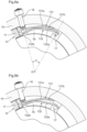
- the part of the elastic member 3 intended to cooperate with the push button 6 of the watch can be offset by an angle ⁇ with center O relative to the part of the elastic member 3 intended to cooperate with the control member 7 of the movement of this watch to trigger a predefined action, as illustrated in Figures 8a and 8b .
- the angle ⁇ is approximately 45°.
- the rigid part 3a of the casing circle 1 is bent and extends over an angle ⁇ with center O of approximately 75°. It is connected to the body 2 by means of a flexible guide member with circular necks constituting the elastic part 3b.
- the two parts of the elastic member 3 intended to cooperate respectively with the push button 6 and with the control member 7 of the movement are typically located in the rigid part 3a.
- the hollow of the bend of the rigid part 3a receives the part of the control member 7 of the movement with which it cooperates.
- the Figure 8a illustrates such a casing circle 1 at rest, that is to say when the push button 6 is not actuated, the elastic member 3 being in its rest position and the control member 7 being in a first position.
- figure 8b illustrates the same casing circle 1 when the push button 6 is actuated, the elastic part 3b of the elastic member 3 being deformed and the control member 7 being in a second position.
- a casing circle 10 for a wristwatch comprises an annular body 11 with center O and rigid as well as a first 131 and a second 132 elastic members forming with said body 11 a single-piece assembly.
- Each of said elastic members 131, 132 comprises a rigid part 131a, 132a movable relative to the body 11, and an elastic part 131b, 132b connecting the latter to the body 11.
- the rigid part 131a of the casing circle 10 is connected to the body 11 by means of an elastic part 131b consisting of a flexible guide member with circular necks.
- the rigid part 132a of the casing circle 10 is connected to the body 11 by means of an elastic part 132b consisting of a flexible guide member with circular necks.
- FIGS. 9a and 9b illustrate the casing ring 10 mounted in a watch. As for the first embodiment of the invention, it is arranged around the movement of this watch and inside its caseband 15.
- the first elastic member 131 cooperates, typically directly, on the one hand with a push button 16 of the watch, said button 16 passing through the caseband 15 and thus being partly outside the case of this watch as in the embodiment illustrated in the Figures 4 and 5 , and on the other hand with the second elastic member 132.
- the second elastic member 132 cooperates, typically directly, on the one hand with the first elastic member 131 and on the other hand with a movement control member 17 such as a control lever of which only a part is visible to the eye.
- Figures 9a and 9b .
- the first and second elastic members are arranged in series, that is to say arranged so that the actuation of said first elastic member 131 from outside the box actuates said control member 17 via said second elastic member 132.
- the rigid part 131a is moved towards the interior of the body 11 by deformation of the flexible guide member with circular necks 131b and acts in turn, by means of its side oriented towards the interior of the body 11, on the rigid part 132a of the second elastic member 132.
- the rigid part 132a is thus moved towards the interior of the body 11 by deformation of the flexible guide member with circular necks 132b and acts in turn on the control member 17 to trigger a predefined action.
- the part of the control member 17 intended to cooperate with the rigid part 132a is offset by an angle ⁇ of center O of approximately 45° relative to the axis of movement of the push button 16.
- the rigid part 131a of the casing circle 10 extends over a center angle O of approximately 35° and the rigid part 132a of the casing circle 10 extends over a center angle O of approximately 50°, these angles intersecting.
- the casing circle 10 is designed so that the rigid parts 131a, 132a of its elastic members 131, 132 are able to move with an amplitude sufficient to actuate the control member 17. This amplitude depends essentially on the deformation properties of the elastic parts 131b, 132b.
- the button 16 is typically a start/stop pushbutton or a reset pushbutton for a chronograph mechanism and the control member is typically a control lever 17 of a chronograph.
- the control member is typically a control lever 17 of a chronograph.
- the body 11 is a closed ring of width “L”. Like the body 2 of the casing circle 1 according to the embodiment illustrated in the Figures 4 and 5 , the body 11 will typically be able to carry its inner edge of the tabs to fix the casing circle 10 relative to the plate of the movement.
- the body 11 also comprises a recess 19 on its upper part in which the elastic members 131, 132 extend in part.
- the elastic members 131, 132 are located mainly above the body 11. They are intended to move in a plane parallel to that in which the body 11 extends, that is to say in a plane parallel to the plate of the movement. The upper part of the recess 19 participates in guiding them in this plane.
- each elastic member 131, 132 moves substantially along an arc of a circle relative to the body 11, the center of this arc of a circle corresponding, for each elastic member, to the pivot center of its flexible guide member with circular necks 131b, 132b.
- the nesting circle 10 illustrated in Figures 9a and 9b comprises two elastic members 131, 132 arranged in series, each of said elastic members comprising a rigid part 131a, 132a in the form of a slightly curved rigid arm and an elastic part 131b, 132 taking the form of a flexible guide member with circular necks.
- the casing circle 10 according to the second embodiment which is an embodiment of the invention, could comprise several series of at least two elastic members.
- Each series of elastic members of the casing circle 10 could comprise more than two elastic members, the said elastic member(s) of the series forming in any case with the body a single-piece assembly.
- each of the elastic members 131, 132 of the casing circle 10 can be connected to the body 11 by a single elastic part 131b, 132b, as in the case illustrated in Figures 9a and 9b , or by several elastic parts, typically two.
- the elastic members of the casing circle 10 may not include a rigid part 131a, 132a. They may then be simple elastic arms.
- Each of the elastic parts 131b, 132b can also take various shapes, other than that of a circular neck. More generally, the shape of the elastic members 131, 132 can vary infinitely as long as their functions are ensured.
- serial arrangement of several elastic members according to the second embodiment which is an embodiment of the invention, as in the case illustrated in Figures 9a and 9b , is particularly suitable for a casing ring intended to be used in a timepiece in which the push button must, typically for reasons of space, be offset by an angle ⁇ of center O relative to the movement control member.
- Such an arrangement remains possible, however, for use in all kinds of timepieces.
- each of the push buttons 6, 16 could be replaced by any other suitable actuator.
- the casing ring according to the invention is typically made of a non-magnetic copper alloy, such as brass, a copper-beryllium alloy or an alloy of copper, nickel and zinc possibly comprising lead known as nickel silver.
- the casing ring is rhodium-plated. It is typically made by mechanical machining, for example by chip removal, by electroerosion or by means of a laser.
- a casing ring for a timepiece comprising a body, at least one first elastic member as described in the first embodiment not falling within the scope of the invention and at least one series of at least two elastic members as described in the second embodiment, which is an embodiment of the invention, said first elastic member and said series of elastic members being arranged to cooperate respectively with first and second actuators intended to be actuated from outside the case of said timepiece to actuate respectively first and second control members of the movement of said timepiece, the body, the first elastic member and the series of at least two elastic members forming a single-piece assembly.
- the casing ring according to the invention can take various shapes, it is typically of the same shape as the watch case of the timepiece in which it is intended to be inserted, typically round as in the examples illustrated in the figures, or else oval, square, rectangular or polygonal for example. In these cases, it is intended to completely surround the movement of said timepiece. In variants, the casing ring according to the invention can also be intended to only partially surround the movement of said timepiece. It can thus be of a shape corresponding to only a portion of the aforementioned shapes, for example in an arc of a circle. It is typically the body of the casing ring which takes this shape.
- the casing circle according to the invention and in particular the fact that its body forms with its elastic members a single-piece assembly, has several advantages.
- each of its elastic members generates a restoring force, which can be used to return the push buttons to position after they have been actuated.
- the spring traditionally present in the push button such as button 106 illustrated in the figure 2 can be deleted.
- the restoring force of each of the elastic members is also easily adjustable, which makes it possible to simply manage the pressure required by the user to actuate a movement control member, this pressure having to be both sufficient to avoid its involuntary actuation but also limited for the comfort of the user.
- the adjustment of this force is typically done by playing on the thickness of the elastic members, on their length and/or on the material used for the production of the casing circle.
- the casing circle according to the invention also has the advantage of angularly offsetting the actuator accessible from the outside of the watch case relative to the control member that it must actuate in order to adapt to the possible size of the watch movement with which it interacts.
Landscapes
- Physics & Mathematics (AREA)
- General Physics & Mathematics (AREA)
- Electric Clocks (AREA)
Claims (12)
- Gehäusering (1; 10) für Uhr, wobei die Uhr ein Uhrwerk und ein Gehäuse umfasst, wobei der Gehäusering (1; 10) einen Körper (2; 11), der dazu bestimmt ist, das Uhrwerk zumindest teilweise zu umgeben, und mindestens ein Betätigungsorgan (3; 131) umfasst, das dazu bestimmt ist, von der Außenseite des Gehäuses betätigt zu werden, um ein Steuerorgan (7; 17) des Uhrwerks zu betätigen, wobei das Betätigungsorgan (3; 131) elastisch ist und mit dem Körper (2; 11) eine Anordnung aus einem Stück bildet, dadurch gekennzeichnet, dass er mindestens ein anderes elastisches Organ (132) umfasst, das derart mit dem Betätigungsorgan (131) in Reihe eingerichtet ist, dass die Betätigung des Betätigungsorgans (131) von der Außenseite des Gehäuses das Steuerorgan (17) über das andere elastische Organ (132) betätigt, wobei das elastische Organ (132) Teil der Anordnung aus einem Stück ist.
- Gehäusering (1; 10) nach Anspruch 1, dadurch gekennzeichnet, dass das Betätigungsorgan (3; 131) einen starren Teil (3a; 131a), der in Bezug auf den Körper (2; 11) beweglich ist, und mindestens einen elastischen Teil (3b; 131b) umfasst, der den starren Teil (3a; 131a) mit dem Körper (2; 11) verbindet.
- Gehäusering (1) nach Anspruch 2, dadurch gekennzeichnet, dass das Betätigungsorgan (3) zwei elastische Teile (3b, 3c) umfasst, die derart auf beiden Seiten des starren Teils (3a) eingerichtet sind, dass sie ihn in Bezug auf den Körper (2) translatorisch führen.
- Gehäusering (1; 10) nach Anspruch 2 oder 3, dadurch gekennzeichnet, dass der starre Teil (3a; 131a) einen Höcker in Bezug auf den oder die elastischen Teil/e (3b; 131b) bildet.
- Gehäusering (10) nach einem der vorhergehenden Ansprüche, dadurch gekennzeichnet, dass das andere elastische Organ auch einen starren Teil (132a), der in Bezug auf den Körper (11) beweglich ist, und mindestens einen elastischen Teil (132b) umfasst, der den starren Teil (131a) mit dem Körper (11) verbindet.
- Gehäusering (1; 10) nach einem der vorhergehenden Ansprüche, dadurch gekennzeichnet, dass die Anordnung aus einem Stück aus einer nicht magnetischen Kupferlegierung besteht, die vorzugsweise ausgewählt ist aus Messing, einer Kupfer-Beryllium-Legierung oder einer Kupfer-, Nickel- und Zinklegierung, die gegebenenfalls Blei umfasst.
- Gehäusering (1; 10) nach einem der vorhergehenden Ansprüche, dadurch gekennzeichnet, dass er eine Form aufweist, die rund, quadratisch, oval, rechteckig ist oder einem Abschnitt der Formen entspricht, zum Beispiel kreisbogenförmig.
- Uhr, wie beispielsweise eine Armbanduhr, eine Taschenuhr, eine Pendeluhr oder eine Pendulette, die einen Gehäusering (1; 10) nach einem der Ansprüche 1 bis 7 umfasst.
- Uhr nach Anspruch 8, dadurch gekennzeichnet, dass sie ein Wirkglied (6; 16) umfasst, das sich zumindest teilweise auf der Außenseite des Gehäuses befindet und dessen Betätigung das Betätigungsorgan (2; 131) derart elastisch verformt, dass es direkt oder indirekt über das andere elastische Organ (132) das Steuerorgan (17) betätigt.
- Uhr nach Anspruch 9, dadurch gekennzeichnet, dass das Wirkglied (6; 16) und das Steuerorgan in Bezug aufeinander um einen Winkel α versetzt sind, dessen Mittelpunkt O dem Mittelpunkt des Körpers (2; 11) entspricht, wobei der Winkel α mindestens 5°, vorzugsweise mindestens 10°, vorzugsweise mindestens 20°, vorzugsweise mindestens 30°, ferner vorzugsweise mindestens 40° beträgt.
- Uhr nach Anspruch 9 oder 10, dadurch gekennzeichnet, dass das Wirkglied (6; 16) ein Druckknopf ist, der den Mittelteil des Gehäuses durchquert.
- Uhr nach einem der Ansprüche 8 bis 10, dadurch gekennzeichnet, dass das Steuerorgan (7; 17) ein Steuerhebel wie beispielsweise ein Chronographen-Steuerhebel ist.
Priority Applications (1)
| Application Number | Priority Date | Filing Date | Title |
|---|---|---|---|
| EP19166736.9A EP3719582B1 (de) | 2019-04-02 | 2019-04-02 | Gehäusering für uhr |
Applications Claiming Priority (1)
| Application Number | Priority Date | Filing Date | Title |
|---|---|---|---|
| EP19166736.9A EP3719582B1 (de) | 2019-04-02 | 2019-04-02 | Gehäusering für uhr |
Publications (2)
| Publication Number | Publication Date |
|---|---|
| EP3719582A1 EP3719582A1 (de) | 2020-10-07 |
| EP3719582B1 true EP3719582B1 (de) | 2024-12-11 |
Family
ID=66091911
Family Applications (1)
| Application Number | Title | Priority Date | Filing Date |
|---|---|---|---|
| EP19166736.9A Active EP3719582B1 (de) | 2019-04-02 | 2019-04-02 | Gehäusering für uhr |
Country Status (1)
| Country | Link |
|---|---|
| EP (1) | EP3719582B1 (de) |
Citations (1)
| Publication number | Priority date | Publication date | Assignee | Title |
|---|---|---|---|---|
| FR2341154A1 (fr) * | 1976-02-12 | 1977-09-09 | Bulova Watch Co Inc | Anneau de montage pour mouvement d'horlogerie |
Family Cites Families (3)
| Publication number | Priority date | Publication date | Assignee | Title |
|---|---|---|---|---|
| FR2548797A1 (fr) * | 1983-07-05 | 1985-01-11 | Yema | Dispositif de commande et de reglage de positionnement d'une lunette de montre |
| EP1710635A1 (de) * | 2005-04-04 | 2006-10-11 | Bruno Affolter S.A. | Betätigungsvorrichtung für eine Uhr und eine Uhr mit derartiger Vorrichtung |
| EP1890202A1 (de) * | 2006-08-17 | 2008-02-20 | The Swatch Group Research and Development Ltd. | Vorrichtung zur Betätigung einer Uhr |
-
2019
- 2019-04-02 EP EP19166736.9A patent/EP3719582B1/de active Active
Patent Citations (1)
| Publication number | Priority date | Publication date | Assignee | Title |
|---|---|---|---|---|
| FR2341154A1 (fr) * | 1976-02-12 | 1977-09-09 | Bulova Watch Co Inc | Anneau de montage pour mouvement d'horlogerie |
Also Published As
| Publication number | Publication date |
|---|---|
| EP3719582A1 (de) | 2020-10-07 |
Similar Documents
| Publication | Publication Date | Title |
|---|---|---|
| EP3559755B1 (de) | Flexible monolithisches bauteil für uhren | |
| EP2048548B1 (de) | Schlagwerk | |
| EP3206089A1 (de) | Resonatormechanismus eines uhrwerks | |
| EP3457221A2 (de) | Oszillator einer uhr mit flexiblem zapfen | |
| EP2776894B1 (de) | Mechanismus zur ansteuerung eines indikators | |
| EP2957964B1 (de) | Kippkupplung für uhren | |
| EP2766778B1 (de) | Uhr | |
| EP3629102B1 (de) | Anzeigemechanismus mit einer fensteranzeige | |
| EP3824354A1 (de) | Uhrwerkmechanismus mit einem nocken | |
| EP3401740A1 (de) | Uhrkomponente zum einpressen ohne gratbildung | |
| EP3719582B1 (de) | Gehäusering für uhr | |
| EP2798414B1 (de) | Feder für uhrwerk | |
| EP2124112A1 (de) | Uhrmechanismus und diesen Mechanismus umfassendes Modul | |
| EP4273635B1 (de) | Uhrwerk | |
| EP1801671A1 (de) | Mit Arretierungsmitteln versehene Kalenderuhr | |
| EP3486735B1 (de) | Uhrwerksmechanismus zur nullrückstellung der sekunde mit schneckennocken | |
| EP3907563B1 (de) | Uhrwerkmechanismus, das ein schwenkorgan umfasst | |
| EP3407142A1 (de) | Uhrwerk mit sekunden-stopp-funktion | |
| CH719059B1 (fr) | Dispositif horloger comprenant un marteau comportant deux parties reliées entre elles par un organe de guidage flexible. | |
| EP1316863A1 (de) | Formuhrwerk mit Chronograph | |
| EP1475682B1 (de) | Chronographuhr mit sofortiger Anzeige von Sekunden-Bruchteilen | |
| EP4425275B1 (de) | Uhrmechanismus | |
| EP4425272B1 (de) | Uhrmechanismus | |
| EP3714336B1 (de) | Halterung eines mobilgeräts mit einer anzeigescheibe | |
| CH720984A1 (fr) | Mécanisme de commande pour pièce d'horlogerie |
Legal Events
| Date | Code | Title | Description |
|---|---|---|---|
| PUAI | Public reference made under article 153(3) epc to a published international application that has entered the european phase |
Free format text: ORIGINAL CODE: 0009012 |
|
| STAA | Information on the status of an ep patent application or granted ep patent |
Free format text: STATUS: THE APPLICATION HAS BEEN PUBLISHED |
|
| AK | Designated contracting states |
Kind code of ref document: A1 Designated state(s): AL AT BE BG CH CY CZ DE DK EE ES FI FR GB GR HR HU IE IS IT LI LT LU LV MC MK MT NL NO PL PT RO RS SE SI SK SM TR |
|
| AX | Request for extension of the european patent |
Extension state: BA ME |
|
| STAA | Information on the status of an ep patent application or granted ep patent |
Free format text: STATUS: REQUEST FOR EXAMINATION WAS MADE |
|
| 17P | Request for examination filed |
Effective date: 20210311 |
|
| RBV | Designated contracting states (corrected) |
Designated state(s): AL AT BE BG CH CY CZ DE DK EE ES FI FR GB GR HR HU IE IS IT LI LT LU LV MC MK MT NL NO PL PT RO RS SE SI SK SM TR |
|
| REG | Reference to a national code |
Ref country code: DE Ref legal event code: R079 Free format text: PREVIOUS MAIN CLASS: G04B0003040000 Ref country code: DE Ref legal event code: R079 Ref document number: 602019063289 Country of ref document: DE Free format text: PREVIOUS MAIN CLASS: G04B0003040000 Ipc: G04B0029000000 |
|
| RIC1 | Information provided on ipc code assigned before grant |
Ipc: G04B 3/04 20060101AFI20220804BHEP |
|
| RIC1 | Information provided on ipc code assigned before grant |
Ipc: G04B 3/04 20060101ALI20220824BHEP Ipc: G04B 29/00 20060101AFI20220824BHEP |
|
| STAA | Information on the status of an ep patent application or granted ep patent |
Free format text: STATUS: EXAMINATION IS IN PROGRESS |
|
| 17Q | First examination report despatched |
Effective date: 20221108 |
|
| P01 | Opt-out of the competence of the unified patent court (upc) registered |
Effective date: 20230521 |
|
| GRAP | Despatch of communication of intention to grant a patent |
Free format text: ORIGINAL CODE: EPIDOSNIGR1 |
|
| STAA | Information on the status of an ep patent application or granted ep patent |
Free format text: STATUS: GRANT OF PATENT IS INTENDED |
|
| INTG | Intention to grant announced |
Effective date: 20240712 |
|
| GRAS | Grant fee paid |
Free format text: ORIGINAL CODE: EPIDOSNIGR3 |
|
| GRAA | (expected) grant |
Free format text: ORIGINAL CODE: 0009210 |
|
| STAA | Information on the status of an ep patent application or granted ep patent |
Free format text: STATUS: THE PATENT HAS BEEN GRANTED |
|
| AK | Designated contracting states |
Kind code of ref document: B1 Designated state(s): AL AT BE BG CH CY CZ DE DK EE ES FI FR GB GR HR HU IE IS IT LI LT LU LV MC MK MT NL NO PL PT RO RS SE SI SK SM TR |
|
| REG | Reference to a national code |
Ref country code: GB Ref legal event code: FG4D Free format text: NOT ENGLISH |
|
| REG | Reference to a national code |
Ref country code: CH Ref legal event code: EP |
|
| REG | Reference to a national code |
Ref country code: IE Ref legal event code: FG4D Free format text: LANGUAGE OF EP DOCUMENT: FRENCH |
|
| REG | Reference to a national code |
Ref country code: DE Ref legal event code: R096 Ref document number: 602019063289 Country of ref document: DE |
|
| REG | Reference to a national code |
Ref country code: LT Ref legal event code: MG9D |
|
| PG25 | Lapsed in a contracting state [announced via postgrant information from national office to epo] |
Ref country code: HR Free format text: LAPSE BECAUSE OF FAILURE TO SUBMIT A TRANSLATION OF THE DESCRIPTION OR TO PAY THE FEE WITHIN THE PRESCRIBED TIME-LIMIT Effective date: 20241211 |
|
| PG25 | Lapsed in a contracting state [announced via postgrant information from national office to epo] |
Ref country code: FI Free format text: LAPSE BECAUSE OF FAILURE TO SUBMIT A TRANSLATION OF THE DESCRIPTION OR TO PAY THE FEE WITHIN THE PRESCRIBED TIME-LIMIT Effective date: 20241211 |
|
| PG25 | Lapsed in a contracting state [announced via postgrant information from national office to epo] |
Ref country code: BG Free format text: LAPSE BECAUSE OF FAILURE TO SUBMIT A TRANSLATION OF THE DESCRIPTION OR TO PAY THE FEE WITHIN THE PRESCRIBED TIME-LIMIT Effective date: 20241211 |
|
| REG | Reference to a national code |
Ref country code: NL Ref legal event code: MP Effective date: 20241211 |
|
| PG25 | Lapsed in a contracting state [announced via postgrant information from national office to epo] |
Ref country code: ES Free format text: LAPSE BECAUSE OF FAILURE TO SUBMIT A TRANSLATION OF THE DESCRIPTION OR TO PAY THE FEE WITHIN THE PRESCRIBED TIME-LIMIT Effective date: 20241211 |
|
| PG25 | Lapsed in a contracting state [announced via postgrant information from national office to epo] |
Ref country code: NO Free format text: LAPSE BECAUSE OF FAILURE TO SUBMIT A TRANSLATION OF THE DESCRIPTION OR TO PAY THE FEE WITHIN THE PRESCRIBED TIME-LIMIT Effective date: 20250311 |
|
| PG25 | Lapsed in a contracting state [announced via postgrant information from national office to epo] |
Ref country code: LV Free format text: LAPSE BECAUSE OF FAILURE TO SUBMIT A TRANSLATION OF THE DESCRIPTION OR TO PAY THE FEE WITHIN THE PRESCRIBED TIME-LIMIT Effective date: 20241211 Ref country code: GR Free format text: LAPSE BECAUSE OF FAILURE TO SUBMIT A TRANSLATION OF THE DESCRIPTION OR TO PAY THE FEE WITHIN THE PRESCRIBED TIME-LIMIT Effective date: 20250312 |
|
| PG25 | Lapsed in a contracting state [announced via postgrant information from national office to epo] |
Ref country code: RS Free format text: LAPSE BECAUSE OF FAILURE TO SUBMIT A TRANSLATION OF THE DESCRIPTION OR TO PAY THE FEE WITHIN THE PRESCRIBED TIME-LIMIT Effective date: 20250311 |
|
| PG25 | Lapsed in a contracting state [announced via postgrant information from national office to epo] |
Ref country code: NL Free format text: LAPSE BECAUSE OF FAILURE TO SUBMIT A TRANSLATION OF THE DESCRIPTION OR TO PAY THE FEE WITHIN THE PRESCRIBED TIME-LIMIT Effective date: 20241211 |
|
| REG | Reference to a national code |
Ref country code: AT Ref legal event code: MK05 Ref document number: 1750880 Country of ref document: AT Kind code of ref document: T Effective date: 20241211 |
|
| PG25 | Lapsed in a contracting state [announced via postgrant information from national office to epo] |
Ref country code: SM Free format text: LAPSE BECAUSE OF FAILURE TO SUBMIT A TRANSLATION OF THE DESCRIPTION OR TO PAY THE FEE WITHIN THE PRESCRIBED TIME-LIMIT Effective date: 20241211 |
|
| PG25 | Lapsed in a contracting state [announced via postgrant information from national office to epo] |
Ref country code: PL Free format text: LAPSE BECAUSE OF FAILURE TO SUBMIT A TRANSLATION OF THE DESCRIPTION OR TO PAY THE FEE WITHIN THE PRESCRIBED TIME-LIMIT Effective date: 20241211 |
|
| PG25 | Lapsed in a contracting state [announced via postgrant information from national office to epo] |
Ref country code: IS Free format text: LAPSE BECAUSE OF FAILURE TO SUBMIT A TRANSLATION OF THE DESCRIPTION OR TO PAY THE FEE WITHIN THE PRESCRIBED TIME-LIMIT Effective date: 20250411 |
|
| PG25 | Lapsed in a contracting state [announced via postgrant information from national office to epo] |
Ref country code: PT Free format text: LAPSE BECAUSE OF FAILURE TO SUBMIT A TRANSLATION OF THE DESCRIPTION OR TO PAY THE FEE WITHIN THE PRESCRIBED TIME-LIMIT Effective date: 20250411 |
|
| PG25 | Lapsed in a contracting state [announced via postgrant information from national office to epo] |
Ref country code: EE Free format text: LAPSE BECAUSE OF FAILURE TO SUBMIT A TRANSLATION OF THE DESCRIPTION OR TO PAY THE FEE WITHIN THE PRESCRIBED TIME-LIMIT Effective date: 20241211 |
|
| PGFP | Annual fee paid to national office [announced via postgrant information from national office to epo] |
Ref country code: CH Payment date: 20250501 Year of fee payment: 7 |
|
| PG25 | Lapsed in a contracting state [announced via postgrant information from national office to epo] |
Ref country code: AT Free format text: LAPSE BECAUSE OF FAILURE TO SUBMIT A TRANSLATION OF THE DESCRIPTION OR TO PAY THE FEE WITHIN THE PRESCRIBED TIME-LIMIT Effective date: 20241211 Ref country code: RO Free format text: LAPSE BECAUSE OF FAILURE TO SUBMIT A TRANSLATION OF THE DESCRIPTION OR TO PAY THE FEE WITHIN THE PRESCRIBED TIME-LIMIT Effective date: 20241211 |
|
| PG25 | Lapsed in a contracting state [announced via postgrant information from national office to epo] |
Ref country code: SK Free format text: LAPSE BECAUSE OF FAILURE TO SUBMIT A TRANSLATION OF THE DESCRIPTION OR TO PAY THE FEE WITHIN THE PRESCRIBED TIME-LIMIT Effective date: 20241211 |
|
| PG25 | Lapsed in a contracting state [announced via postgrant information from national office to epo] |
Ref country code: CZ Free format text: LAPSE BECAUSE OF FAILURE TO SUBMIT A TRANSLATION OF THE DESCRIPTION OR TO PAY THE FEE WITHIN THE PRESCRIBED TIME-LIMIT Effective date: 20241211 |
|
| PG25 | Lapsed in a contracting state [announced via postgrant information from national office to epo] |
Ref country code: IT Free format text: LAPSE BECAUSE OF FAILURE TO SUBMIT A TRANSLATION OF THE DESCRIPTION OR TO PAY THE FEE WITHIN THE PRESCRIBED TIME-LIMIT Effective date: 20241211 |
|
| PG25 | Lapsed in a contracting state [announced via postgrant information from national office to epo] |
Ref country code: SE Free format text: LAPSE BECAUSE OF FAILURE TO SUBMIT A TRANSLATION OF THE DESCRIPTION OR TO PAY THE FEE WITHIN THE PRESCRIBED TIME-LIMIT Effective date: 20241211 |
|
| REG | Reference to a national code |
Ref country code: DE Ref legal event code: R097 Ref document number: 602019063289 Country of ref document: DE |
|
| PG25 | Lapsed in a contracting state [announced via postgrant information from national office to epo] |
Ref country code: DK Free format text: LAPSE BECAUSE OF FAILURE TO SUBMIT A TRANSLATION OF THE DESCRIPTION OR TO PAY THE FEE WITHIN THE PRESCRIBED TIME-LIMIT Effective date: 20241211 |
|
| PLBE | No opposition filed within time limit |
Free format text: ORIGINAL CODE: 0009261 |
|
| STAA | Information on the status of an ep patent application or granted ep patent |
Free format text: STATUS: NO OPPOSITION FILED WITHIN TIME LIMIT |
|
| REG | Reference to a national code |
Ref country code: DE Ref legal event code: R119 Ref document number: 602019063289 Country of ref document: DE |
|
| 26N | No opposition filed |
Effective date: 20250912 |
|
| PG25 | Lapsed in a contracting state [announced via postgrant information from national office to epo] |
Ref country code: LU Free format text: LAPSE BECAUSE OF NON-PAYMENT OF DUE FEES Effective date: 20250402 |
|
| PG25 | Lapsed in a contracting state [announced via postgrant information from national office to epo] |
Ref country code: MC Free format text: LAPSE BECAUSE OF FAILURE TO SUBMIT A TRANSLATION OF THE DESCRIPTION OR TO PAY THE FEE WITHIN THE PRESCRIBED TIME-LIMIT Effective date: 20241211 |
|
| GBPC | Gb: european patent ceased through non-payment of renewal fee |
Effective date: 20250402 |
|
| REG | Reference to a national code |
Ref country code: BE Ref legal event code: MM Effective date: 20250430 |
|
| PG25 | Lapsed in a contracting state [announced via postgrant information from national office to epo] |
Ref country code: DE Free format text: LAPSE BECAUSE OF NON-PAYMENT OF DUE FEES Effective date: 20251104 |
|
| PG25 | Lapsed in a contracting state [announced via postgrant information from national office to epo] |
Ref country code: GB Free format text: LAPSE BECAUSE OF NON-PAYMENT OF DUE FEES Effective date: 20250402 |
|
| PG25 | Lapsed in a contracting state [announced via postgrant information from national office to epo] |
Ref country code: FR Free format text: LAPSE BECAUSE OF NON-PAYMENT OF DUE FEES Effective date: 20250430 |
|
| PG25 | Lapsed in a contracting state [announced via postgrant information from national office to epo] |
Ref country code: BE Free format text: LAPSE BECAUSE OF NON-PAYMENT OF DUE FEES Effective date: 20250430 |
|
| PG25 | Lapsed in a contracting state [announced via postgrant information from national office to epo] |
Ref country code: IE Free format text: LAPSE BECAUSE OF NON-PAYMENT OF DUE FEES Effective date: 20250402 |