EP3560792A2 - Method for operating a railway safety system - Google Patents
Method for operating a railway safety system Download PDFInfo
- Publication number
- EP3560792A2 EP3560792A2 EP19166128.9A EP19166128A EP3560792A2 EP 3560792 A2 EP3560792 A2 EP 3560792A2 EP 19166128 A EP19166128 A EP 19166128A EP 3560792 A2 EP3560792 A2 EP 3560792A2
- Authority
- EP
- European Patent Office
- Prior art keywords
- rail vehicle
- ids1
- identification data
- ids2
- rule
- Prior art date
- Legal status (The legal status is an assumption and is not a legal conclusion. Google has not performed a legal analysis and makes no representation as to the accuracy of the status listed.)
- Granted
Links
Images

Classifications
-
- B—PERFORMING OPERATIONS; TRANSPORTING
- B61—RAILWAYS
- B61L—GUIDING RAILWAY TRAFFIC; ENSURING THE SAFETY OF RAILWAY TRAFFIC
- B61L25/00—Recording or indicating positions or identities of vehicles or trains or setting of track apparatus
- B61L25/02—Indicating or recording positions or identities of vehicles or trains
- B61L25/04—Indicating or recording train identities
- B61L25/043—Indicating or recording train identities using inductive tags
-
- B—PERFORMING OPERATIONS; TRANSPORTING
- B61—RAILWAYS
- B61L—GUIDING RAILWAY TRAFFIC; ENSURING THE SAFETY OF RAILWAY TRAFFIC
- B61L1/00—Devices along the route controlled by interaction with the vehicle or train
- B61L1/02—Electric devices associated with track, e.g. rail contacts
-
- B—PERFORMING OPERATIONS; TRANSPORTING
- B61—RAILWAYS
- B61L—GUIDING RAILWAY TRAFFIC; ENSURING THE SAFETY OF RAILWAY TRAFFIC
- B61L25/00—Recording or indicating positions or identities of vehicles or trains or setting of track apparatus
- B61L25/02—Indicating or recording positions or identities of vehicles or trains
- B61L25/04—Indicating or recording train identities
- B61L25/048—Indicating or recording train identities using programmable tags
-
- B—PERFORMING OPERATIONS; TRANSPORTING
- B61—RAILWAYS
- B61L—GUIDING RAILWAY TRAFFIC; ENSURING THE SAFETY OF RAILWAY TRAFFIC
- B61L29/00—Safety means for rail/road crossing traffic
- B61L29/08—Operation of gates; Combined operation of gates and signals
- B61L29/18—Operation by approaching rail vehicle or train
- B61L29/22—Operation by approaching rail vehicle or train electrically
- B61L29/222—Operation by approaching rail vehicle or train electrically using conductor circuits with separate contacts or conductors
- B61L29/224—Operation by approaching rail vehicle or train electrically using conductor circuits with separate contacts or conductors using rail contacts
-
- B—PERFORMING OPERATIONS; TRANSPORTING
- B61—RAILWAYS
- B61L—GUIDING RAILWAY TRAFFIC; ENSURING THE SAFETY OF RAILWAY TRAFFIC
- B61L29/00—Safety means for rail/road crossing traffic
- B61L29/08—Operation of gates; Combined operation of gates and signals
- B61L29/18—Operation by approaching rail vehicle or train
- B61L29/22—Operation by approaching rail vehicle or train electrically
- B61L29/226—Operation by approaching rail vehicle or train electrically using track-circuits, closed or short-circuited by train or using isolated rail-sections
-
- B—PERFORMING OPERATIONS; TRANSPORTING
- B61—RAILWAYS
- B61L—GUIDING RAILWAY TRAFFIC; ENSURING THE SAFETY OF RAILWAY TRAFFIC
- B61L29/00—Safety means for rail/road crossing traffic
- B61L29/24—Means for warning road traffic that a gate is closed or closing, or that rail traffic is approaching, e.g. for visible or audible warning
- B61L29/28—Means for warning road traffic that a gate is closed or closing, or that rail traffic is approaching, e.g. for visible or audible warning electrically operated
- B61L29/32—Timing, e.g. advance warning of approaching train
-
- B—PERFORMING OPERATIONS; TRANSPORTING
- B61—RAILWAYS
- B61L—GUIDING RAILWAY TRAFFIC; ENSURING THE SAFETY OF RAILWAY TRAFFIC
- B61L1/00—Devices along the route controlled by interaction with the vehicle or train
- B61L1/16—Devices for counting axles; Devices for counting vehicles
Definitions
- the invention relates to a track device and a method for controlling a railway safety system.
- the invention has for its object to further improve a method of the type specified in terms of determining an optimal switching time for the railway safety system on.
- the track device checks on the basis of the at least one measurement result and one or more identification data records as to whether the approaching rail vehicle is to be assigned to or one of the identification data sets and is a control train described by the identification data record to be assigned, and the route device in the case of a recognized one Regelzugs from a memory in which at least one auxiliary parameter value is stored for the detected rule, this reads at least one auxiliary parameter value and the switching time determined using this at least one read auxiliary parameter value.
- a significant advantage of the method according to the invention is that the determination of the switching time for the railway safety system can be carried out on a regular basis, ie on the basis of detected control trains. If it is determined that an approaching rail vehicle is a control train according to an identification data record, then the determination of the changeover time can take place in an optimal manner by referring to findings for precisely this control train. If an approaching rail vehicle is not recognized as a regular train, then the control of the railway safety system can take place, as is customary today and has been described for example in the above-mentioned published patent application. In other words, the inventive idea is to optimize the determination of the switching time for such rail vehicles whose arrival time at the railway safety system is particularly well predictable or predictable due to their Regelzugkonformen behavior.
- the track device draws at least one of the following measurement results, preferably at least two of the following measurement results, to determine whether the approaching rail vehicle is to be assigned to the or one of the identification data sets and a control train described by the identification data record to be assigned: the time interval between rail vehicles Cycle between rolling stock, the absolute time, the speed of the rail vehicle, the acceleration of the rail vehicle, the total number of axles of the rail vehicle, the spacings of the rail vehicle, the train length of the rail vehicle, the axle load of the rail vehicle, the axle loads of driven and / or non-powered cars in case a multi-unit rail vehicle, the number of powered vehicles or locomotives of the rail vehicle, the number of traction units of the railway vehicle, the number of pantographs on the overhead contact line of the rail vehicle and / or the traction energy of the rail vehicle.
- the track device carries out the check as to whether the approaching rail vehicle is a regular train on the basis of a self-created identification data record which it has itself prepared by evaluating measurement results in approach events in the past.
- the route device generates the identification data record itself by checking whether the measured measurement results are identical or at least sufficiently similar according to a predetermined similarity threshold in the case of approach events in the past for a subset of the rail vehicles Subset on the basis of considered as similar measurement results (for example, by averaging the similarly regarded measurement results) generates identification data for the identification record and forms the identification record using the generated identification data.
- the route device preferably draws at least one of the above-mentioned gauges in order to form the identification data record.
- Types of measurement results preferably at least two of the above.
- G Types of measurement results.
- the route device carries out the check as to whether the approaching rail vehicle is a control train on the basis of an externally specified identification data record.
- the track device the examination of whether the approaching rail vehicle is a rule train, on the basis of a modified identification data set performs, by evaluating measurement results in approach events in the past by modifying an earlier created, externally specified or previously self-modified identification data set created himself.
- the route device modifies the existing identification data record and forms a more closely defined identification data record if the measurement results measured at approach events in the past show that rail vehicles that are detected by the existing identification data record and recognized as a corresponding control train, would also be covered by the more narrowly defined identification record.
- the route device modifies the predefined identification data record, if the measurement results measured during approach events in the past show that rail vehicles that are detected by the existing identification data record and recognized as the same rule train are assigned to different subgroups of rule trains can.
- the route device pulls at least one of the o. G. To form the modified identification data record. Types of measurement results, preferably at least two of the above. G. Types of measurement results.
- each at least one identification record in particular a self-created, an externally given or previously self-modified identification record, and for each rule at least each rulezugindividueller Auxiliary parameter value is stored for determining the switching time and the link device checks on the basis of the at least one measurement result in each approach event respectively, if the approaching rail vehicle is one of the rules and optionally reads the at least one corresponding auxiliary parameter value from the memory for the detected rule.
- the route device for the one or more rules forms the at least one auxiliary parameter value itself.
- each of the or at least one of the rule-specific auxiliary parameter values is a quantitative quantity to be taken into account quantitatively in the calculation of the switching time (for example, a fixed lead time, a fixed hold time at one or more breakpoints in front of the railroad safety system, standard acceleration for the regular train, allowed maximum speed, etc.).
- the or at least one of the rule-specific auxiliary parameter values is an identifier that defines the calculation formula in the calculation of the switching time (for example identifier "1"): calculation of the switching instant without consideration of the acceleration currently measured by the sensor identifier "2": Calculation of the changeover time taking into account the acceleration currently measured by the sensor, etc.).
- auxiliary parameter values may advantageously also be stored for a period of time.
- the railway safety system is preferably a railroad crossing.
- the invention also relates to a track device for controlling a railway safety system, wherein the track device has a control device that evaluates at least approaching a rail vehicle to the railway safety system rail-related measurement result and determined based on the measurement result a switching time for the railway safety system.
- the track device is designed such that it checks on the basis of the at least one measurement result and on the basis of one or more identification data records as to whether the approaching rail vehicle is to be assigned to or one of the identification data sets and is a control train described by the identification data record to be assigned, and Track device is designed such that it is in the case of a detected rule from a memory in which for the detected rule train at least one auxiliary parameter value is stored, this reads at least one auxiliary parameter value and determines the switching time using this at least one read auxiliary parameter value.
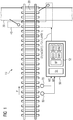
- FIG. 1 shows a railway track 10, which is crossed in the region of a crossing point 20 of a road 30 and there is equipped with a railway safety device 40 in the form of a railroad crossing.
- the railway safety system 40 and one or more sensors arranged on the railway track system 10 are connected to a track device 50.
- the track device 50 is connected to two sensors 60 and 70, of which the sensor 60 transmits a measurement result M1 and the sensor 70 transmits a measurement result M2 to the track device 50.
- the two sensors 60 and 70 detect along the direction of travel P - ie in the FIG. 1 From left to right - on the railway safety device 40 moving rail vehicle, for example by an axle detection of the passing rail vehicle, and pass a corresponding measurement result M1 or M2 to the track device 50 on.
- the two sensors 60 and 70 can transmit overrun events as such to the track device 50, or derived therefrom measurement results or other measurement results, in particular for example one or two of the following measurement results: the time interval between rail vehicles, the time cycle between rail vehicles, the absolute time, the Speed of the rail vehicle, the acceleration of the rail vehicle, the total number of axles of the rail vehicle, the axial spacing of the rail vehicle, the train length of the rail vehicle, the axle load of the rail vehicle, the number of traction units of the rail vehicle, the number of conductors on the overhead line of the rail vehicle and / or the traction energy of the rail vehicle.
- the route device 50 is equipped with a computer 51 and a memory 52.
- An operating program BP is stored in the memory 52 which, when executed by the computer 51, enables the track device 50 and causes it to control the railway safety system 40 and to determine a changeover point to the railway safety system 40 for this purpose.
- the switching time can be transmitted as such to the railway safety system 40, which subsequently generates the corresponding closing command for closing the railway safety system 40 on the basis of the received switching time; Alternatively, the switching time can be transmitted indirectly in the form of a control signal ST, which transmits the corresponding closing command itself to the railway safety system 40 at the switching time.
- identification records are stored, which uses the operating program BP for the operation of the railway safety system 40.
- two identification records which are identified by the reference numerals IDS1 and IDS2.
- Each of the two identification records IDS1 and IDS2 defines each a rule train, which is to be recognized by the route device and to be treated in a predetermined manner with respect to the switching time.
- auxiliary parameter values are stored in the memory 52, which in each case directly indicate the changeover point of the railway safety system 40 for a recognized control train or at least enable a determination of the changeover time on the basis thereof.
- auxiliary parameter set HW1 is assigned to the identification data record IDS1; this means that the auxiliary parameter set HW1 contains auxiliary parameter values for rail vehicles, which are detected by the identification data record IDS1. Accordingly, the auxiliary parameter set HW2 contains auxiliary parameter values for those rail vehicles which fall under the definition of the identification data record IDS2.
- identification data sets and auxiliary parameters for two control sequences are stored in the memory 52.
- the route device 50 is preferably operated as follows: If a rail vehicle passes the two sensors 60 and 70 as it travels along the direction of travel P, the corresponding measurement results M1 and M2 are sent to the route device 50.
- the operating program BP evaluates the measurement results M1 and M2 and checks whether the identification data sets IDS1 and IDS2 Allocate approaching rail vehicle one of the two identification records IDS1 or IDS2 leaves. If this is the case, the operating program BP concludes from this that the approaching rail vehicle is a control train which is to be treated in accordance with the auxiliary parameter set HW1 or HW2 associated with the identification data record.
- the approaching rail vehicle is a control train which is described by the identification data record IDS1 or is detected by it. Accordingly, the operating program BP will read the associated auxiliary parameter set HW1 from the memory 52 for the detected control train or for the identification data set IDS1 and determine the switching time for the railway safety system 40 on the basis of the auxiliary parameter values of the auxiliary parameter set HW1.
- the rule-specific auxiliary parameter sets HW1 and HW2 can include one or more quantitative variables that are to be taken into account quantitatively in the calculation of the switching time, for example, a fixed lead time, a fixed holding time at one or more breakpoints in front of the railway safety system, a standard acceleration for the rule train , a permitted maximum speed, etc.
- one or more identifiers may be stored in the auxiliary parameter sets HW1 and HW2 as rule-specific auxiliary parameter values that define the calculation formula when calculating the switchover time.
- an identifier "1" may indicate that the calculation of the switchover instant should be done without taking into account the train's currently measured acceleration of the train;
- An identifier "2" can indicate that the calculation of the switching time should be made taking into account the acceleration currently measured by the sensor.
- further identifiers for handling the respective rule can be defined.
- FIG. 2 shows a first embodiment of an operating program BP, which in the memory 52 of the track device 50 according to FIG. 1 can be stored and is suitable for operation of the computer 51.
- an operating program BP which in the memory 52 of the track device 50 according to FIG. 1 can be stored and is suitable for operation of the computer 51.
- the operating program BP comprises a read-in module 100 for detecting the measurement results M1 and M2 according to FIG. 1 ,
- the read-in module 100 If the read-in module 100 has measurement results, it is checked in a subsequent test step 110 whether identification data records are present in the memory 52.
- a comparison step 120 is continued, in which the measurement results M1 and M2 are compared with the identification data sets IDS1 and IDS2.
- a standard activation step 130 is carried out, which performs the control of the railway safety system 40 with a standard switching time Tu (STD)) and, for example, a corresponding one Control signal ST (Tu (STD)) setting the standard switching time Tu (STD)) to the railway safety relay 40 according to FIG FIG. 1 transmitted.
- the standard switching time Tu (STD)) can be calculated, for example, by adding the transition time determined by the sensors 60 and 70 to a predetermined standard delay value.
- the comparison step 120 If, however, it is determined in the comparison step 120 that one of the two identification data sets, for example the identification data record IDS1, can be assigned to the measurement results M1 and M2, and thus it can be concluded that the approaching rail vehicle is a regulatory train according to the identification data record IDS1, then continued with a read-out step 140.
- one of the two identification data sets for example the identification data record IDS1
- the computer 51 reads from the memory 52 the auxiliary parameter set HW1, which is assigned to the identification data record IDS1.
- a subordinate control-individual control step 150 on the basis of the rule-specific auxiliary parameter values which are stored in the auxiliary parameter set HW1, the regular-individual changeover time for the railway safety system 40 is determined.
- the switching timing Tu (HW1)) or a corresponding control signal ST (Tu (HW1)) is formed and transmitted to the railway safety relay 40.
- the regular individual switching time Tu (HW1)) can be calculated for example by adding the determined by the sensors 60 and 70 Kochfahrzeitticians with a regelzugindividual delay value.
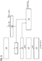
- FIG. 3 shows a second embodiment of an operating program BP, the control of the railway safety device 40 by the track device 50 according to FIG. 1 allows.
- the operating program BP according to FIG. 3 with respect to the program module 100, the checking step 110, the comparing step 120, the standard driving step 130, the reading step 140, and the rule-individual driving step 150 corresponds to the operation program BP according to FIG. 2 so, in this regard, the above explanations in connection with the FIG. 2 referenced.
- the operating program BP according to FIG. 3 has an additional data-set-forming module 160 which cooperates with the test step 110 and the read-in module 100.
- the program module BP works as follows: If it is determined in test step 110 that no identification data records are stored in memory 52 at all and, for this reason, a comparison with existing identification data sets can not take place, control of the railway safety system 40 is carried out in accordance with standard activation step 130, as described in connection with FIG FIG. 2 has been explained.
- the data set-forming module 160 is activated, which independently uses the data records M1, M2 of the read-in module 100 that are present on the input side, identification data sets, for example the identification data records IDS1 and IDS2 according to FIG FIG. 1 , generated.
- the record-forming module 160 uses the measurement results M1 and M2 to generate the identification data sets IDS1 and IDS2, preferably by checking whether the past approximation events in the case of a subset of rail vehicles are identical or at least sufficiently similar in accordance with a predetermined similarity threshold, in the case of a detected one Subset generated on the basis of the considered similar measurement results identification data for the identification record and the identification record using the generated identification data forms. A sufficient similarity of a subset of measurement results can be concluded, for example, if the measurement results of this subset do not deviate from the mean value of the respective subset beyond a predetermined extent.
- the data set-forming module 160 uses at least one of the above-mentioned types of measurement results as the measurement result M1 and M2.
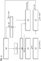
- FIG. 4 shows a third embodiment of an operating program BP
- the computer 51 of the track device 50 according to FIG. 1 can be executed to control the railway safety system 40.
- the program module BP according to FIG. 4 includes all program steps or program modules associated with the Figures 2 and 3 have already been explained; In this regard, reference is made to the above statements.
- a modification module 170 is provided, which cooperates with the comparison step 120 and the read-in module 100 and is configured to modify an identification data record identified in the context of the comparison step 120, for example the identification data record IDS1, as a function of the measurement results M1 and M2 currently acquired by the read-in module 100.
- a modified modification data record IDS1 ' is generated, which is stored in the memory 52 as a replacement for the previously stored earlier identification data record IDS1 there.
- the modified identification data set IDS1 ' replaces the earlier identification data set IDS1, which is stored in the FIG. 1 is shown.
- a more narrowly defined identification data record can be formed, in particular if the measurement results measured during approach events in the past show that rail vehicles that are detected by the identification data record and recognized as a corresponding control code also depend on the more narrowly defined identification data record would be recorded.
- a modification of the identification data record IDS1 is also advantageous if the measurement results measured during approach events in the past show that rail vehicles that are detected by the predefined identification data record and recognized as the same rule train are assigned to different subgroups of rule trains can.
- sub-data records can be generated within the identification data record IDS1, or the existing identification data record IDS1 can be replaced by two new identification data records which are stored in the identification data record IDS1 FIG. 4 are denoted by the reference character IDS1 'and IDS''.
Landscapes
- Engineering & Computer Science (AREA)
- Mechanical Engineering (AREA)
- Automation & Control Theory (AREA)
- Train Traffic Observation, Control, And Security (AREA)
- Electric Propulsion And Braking For Vehicles (AREA)
Abstract
Die Erfindung bezieht sich auf ein Verfahren zum Betreiben einer Streckeneinrichtung (50) zur Ansteuerung einer Eisenbahnsicherungsanlage (40), wobei die Streckeneinrichtung (50) bei Annäherung eines Schienenfahrzeugs an die Eisenbahnsicherungsanlage (40) mit zumindest einem Sensor (60, 70) zumindest ein schienenfahrzeugbezogenes Messergebnis (M1, M2) erfasst und anhand des Messergebnisses (M1, M2) einen Umschaltzeitpunkt (Tu) für die Eisenbahnsicherungsanlage (40) ermittelt. Erfindungsgemäß ist vorgesehen, dass die Streckeneinrichtung (50) anhand des zumindest einen Messergebnisses (M1, M2) und anhand eines oder mehrerer Identifikationsdatensätze (IDS1, IDS2) prüft, ob das sich annähernde Schienenfahrzeug dem oder einem der Identifikationsdatensätze (IDS1, IDS2) zuzuordnen ist und ein durch den zuzuordnenden Identifikationsdatensatz (IDS1, IDS2) beschriebener Regelzug ist, und die Streckeneinrichtung (50) im Falle eines erkannten Regelzugs aus einem Speicher (52), in dem für den erkannten Regelzug zumindest ein Hilfsparameterwert abgespeichert ist, diesen zumindest einen Hilfsparameterwert ausliest und den Umschaltzeitpunkt (Tu) unter Heranziehung dieses zumindest einen ausgelesenen Hilfsparameterwerts ermittelt.The invention relates to a method for operating a track device (50) for controlling a railway safety system (40), wherein the track device (50) with at least one sensor (60, 70) when approaching a rail vehicle to the railway safety system (40) at least one rail vehicle related Measurement result (M1, M2) detected and based on the measurement result (M1, M2) determines a switching time (Tu) for the railway safety system (40). According to the invention, the track device (50) checks on the basis of the at least one measurement result (M1, M2) and on the basis of one or more identification data sets (IDS1, IDS2) as to whether the approaching rail vehicle is to be assigned to the or one of the identification data records (IDS1, IDS2) and a rule train described by the identification data record (IDS1, IDS2) to be assigned, and the route device (50) in the case of a recognized rule train from a memory (52) in which at least one auxiliary parameter value is stored for the detected rule train, reads this at least one auxiliary parameter value and the switching time (Tu) determined using this at least one read auxiliary parameter value.
Description
Die Erfindung bezieht sich auf eine Streckeneinrichtung und ein Verfahren zur Ansteuerung einer Eisenbahnsicherungsanlage.The invention relates to a track device and a method for controlling a railway safety system.
Aus der europäischen Offenlegungsschrift
Der Erfindung liegt die Aufgabe zugrunde, ein Verfahren der eingangs angegebenen Art hinsichtlich der Ermittlung eines optimalen Umschaltzeitpunkts für die Eisenbahnsicherungsanlage weiter zu verbessern.The invention has for its object to further improve a method of the type specified in terms of determining an optimal switching time for the railway safety system on.
Diese Aufgabe wird erfindungsgemäß durch ein Verfahren mit den Merkmalen gemäß Patentanspruch 1 gelöst. Vorteilhafte Ausgestaltungen des erfindungsgemäßen Verfahrens sind in Unteransprüchen angegeben.This object is achieved by a method having the features according to claim 1. Advantageous embodiments of the method according to the invention are specified in subclaims.
Danach ist erfindungsgemäß vorgesehen, dass die Streckeneinrichtung anhand des zumindest einen Messergebnisses und anhand eines oder mehrerer Identifikationsdatensätze prüft, ob das sich annähernde Schienenfahrzeug dem oder einem der Identifikationsdatensätze zuzuordnen ist und ein durch den zuzuordnenden Identifikationsdatensatz beschriebener Regelzug ist, und die Streckeneinrichtung im Falle eines erkannten Regelzugs aus einem Speicher, in dem für den erkannten Regelzug zumindest ein Hilfsparameterwert abgespeichert ist, diesen zumindest einen Hilfsparameterwert ausliest und den Umschaltzeitpunkt unter Heranziehung dieses zumindest einen ausgelesenen Hilfsparameterwerts ermittelt.According to the invention, it is provided that the track device checks on the basis of the at least one measurement result and one or more identification data records as to whether the approaching rail vehicle is to be assigned to or one of the identification data sets and is a control train described by the identification data record to be assigned, and the route device in the case of a recognized one Regelzugs from a memory in which at least one auxiliary parameter value is stored for the detected rule, this reads at least one auxiliary parameter value and the switching time determined using this at least one read auxiliary parameter value.
Ein wesentlicher Vorteil des erfindungsgemäßen Verfahrens besteht darin, dass die Ermittlung des Umschaltzeitpunkts für die Eisenbahnsicherungsanlage regelzugindividuell, also auf der Basis erkannter Regelzüge erfolgen kann. Wird festgestellt, dass ein sich annäherndes Schienenfahrzeug ein Regelzug gemäß einem Identifikationsdatensatz ist, so kann die Ermittlung des Umschaltzeitpunkts in optimaler Weise erfolgen, indem auf Erkenntnisse für eben diesen Regelzug Bezug genommen wird. Wird ein sich annäherndes Schienenfahrzeug nicht als Regelzug erkannt, so kann die Ansteuerung der Eisenbahnsicherungsanlage erfolgen, wie dies heutzutage üblich ist und beispielsweise in der oben genannten Offenlegungsschrift beschrieben worden ist. Mit anderen Worten besteht der erfinderische Gedanke darin, die Bestimmung des Umschaltzeitpunkts für solche Schienenfahrzeuge zu optimieren, deren Ankunftszeit an der Eisenbahnsicherungsanlage aufgrund ihres regelzugkonformen Verhaltens besonders gut abschätzbar bzw. vorhersehbar ist.A significant advantage of the method according to the invention is that the determination of the switching time for the railway safety system can be carried out on a regular basis, ie on the basis of detected control trains. If it is determined that an approaching rail vehicle is a control train according to an identification data record, then the determination of the changeover time can take place in an optimal manner by referring to findings for precisely this control train. If an approaching rail vehicle is not recognized as a regular train, then the control of the railway safety system can take place, as is customary today and has been described for example in the above-mentioned published patent application. In other words, the inventive idea is to optimize the determination of the switching time for such rail vehicles whose arrival time at the railway safety system is particularly well predictable or predictable due to their Regelzugkonformen behavior.
Die Streckeneinrichtung zieht zur Prüfung, ob das sich annähernde Schienenfahrzeug dem oder einem der Identifikationsdatensätze zuzuordnen ist und ein durch den zuzuordnenden Identifikationsdatensatz beschriebener Regelzug ist, zumindest eines der folgenden Messergebnisse, vorzugsweise zumindest zwei der folgenden Messergebnisse heran: den zeitlichen Abstand zwischen Schienenfahrzeugen, den zeitliche Takt zwischen Schienenfahrzeugen, die absolute Uhrzeit, die Geschwindigkeit des Schienenfahrzeugs, die Beschleunigung des Schienenfahrzeugs, die Gesamtachsanzahl des Schienenfahrzeugs, die Achsabstände des Schienenfahrzeugs, die Zuglänge des Schienenfahrzeugs, die Achslast des Schienenfahrzeugs, die Achslasten von angetriebenen und/oder nicht angetriebenen Wagen im Falle eines mehrgliedrigen Schienenfahrzeugs, die Anzahl der angetriebenen Wagen oder Triebfahrzeuge des Schienenfahrzeugs, die Anzahl der Triebfahrzeuge des Schienenfahrzeugs, die Anzahl an der Oberleitung anliegender Stromabnehmer des Schienenfahrzeugs und/oder die Traktionsenergie des Schienenfahrzeugs.The track device draws at least one of the following measurement results, preferably at least two of the following measurement results, to determine whether the approaching rail vehicle is to be assigned to the or one of the identification data sets and a control train described by the identification data record to be assigned: the time interval between rail vehicles Cycle between rolling stock, the absolute time, the speed of the rail vehicle, the acceleration of the rail vehicle, the total number of axles of the rail vehicle, the spacings of the rail vehicle, the train length of the rail vehicle, the axle load of the rail vehicle, the axle loads of driven and / or non-powered cars in case a multi-unit rail vehicle, the number of powered vehicles or locomotives of the rail vehicle, the number of traction units of the railway vehicle, the number of pantographs on the overhead contact line of the rail vehicle and / or the traction energy of the rail vehicle.
Bei einer als vorteilhaft angesehenen Verfahrensvariante ist vorgesehen, dass die Streckeneinrichtung die Prüfung, ob das sich annähernde Schienenfahrzeug ein Regelzug ist, auf der Basis eines selbst erstellten Identifikationsdatensatzes durchführt, den sie durch Auswertung von Messergebnissen bei Annäherungsereignissen in der Vergangenheit selbst erstellt hat.In a method variant which is considered to be advantageous, it is provided that the track device carries out the check as to whether the approaching rail vehicle is a regular train on the basis of a self-created identification data record which it has itself prepared by evaluating measurement results in approach events in the past.
Bei der letztgenannten Verfahrensvariante ist es besonders vorteilhaft, wenn die Streckeneinrichtung den Identifikationsdatensatz selbst erstellt, indem sie prüft, ob bei Annäherungsereignissen in der Vergangenheit bei einer Teilmenge der Schienenfahrzeuge die gemessenen Messergebnisse identisch oder gemäß einer vorgegebenen Ähnlichkeitsschwelle zumindest hinreichend ähnlich sind, im Falle einer erkannten Teilmenge auf der Basis der als ähnlich angesehenen Messergebnisse (beispielsweise durch Mittelwertbildung der als ähnlich angesehenen Messergebnisse) Identifikationsdaten für den Identifikationsdatensatz erzeugt und den Identifikationsdatensatz unter Heranziehung der erzeugten Identifikationsdaten bildet.In the case of the last-mentioned method variant, it is particularly advantageous if the route device generates the identification data record itself by checking whether the measured measurement results are identical or at least sufficiently similar according to a predetermined similarity threshold in the case of approach events in the past for a subset of the rail vehicles Subset on the basis of considered as similar measurement results (for example, by averaging the similarly regarded measurement results) generates identification data for the identification record and forms the identification record using the generated identification data.
Die Streckeneinrichtung zieht zur Bildung des Identifikationsdatensatzes vorzugsweise zumindest eine der o. g. Arten von Messergebnissen, vorzugsweise zumindest zwei der o. g. Arten von Messergebnissen heran.The route device preferably draws at least one of the above-mentioned gauges in order to form the identification data record. Types of measurement results, preferably at least two of the above. G. Types of measurement results.
Bei einer anderen als vorteilhaft angesehenen Verfahrensvariante ist vorgesehen, dass die Streckeneinrichtung die Prüfung, ob das sich annähernde Schienenfahrzeug ein Regelzug ist, auf der Basis eines extern vorgegebenen Identifikationsdatensatzes durchführt.In another method variant considered advantageous, it is provided that the route device carries out the check as to whether the approaching rail vehicle is a control train on the basis of an externally specified identification data record.
Bei einer wiederum anderen als vorteilhaft angesehenen Verfahrensvariante ist vorgesehen, dass die Streckeneinrichtung die Prüfung, ob das sich annähernde Schienenfahrzeug ein Regelzug ist, auf der Basis eines modifizierten Identifikationsdatensatzes durchführt, den sie durch Auswertung von Messergebnissen bei Annäherungsereignissen in der Vergangenheit durch Modifikation eines zu einem früheren Zeitpunkt selbst erstellten, eines extern vorgegebenen oder eines zuvor selbst modifizierten Identifikationsdatensatzes selbst erstellt hat.In yet another method variant considered advantageous, it is provided that the track device the examination of whether the approaching rail vehicle is a rule train, on the basis of a modified identification data set performs, by evaluating measurement results in approach events in the past by modifying an earlier created, externally specified or previously self-modified identification data set created himself.
Bei der letztgenannten Verfahrensvariante ist es besonders vorteilhaft, wenn die Streckeneinrichtung den vorhandenen Identifikationsdatensatz modifiziert und einen enger definierten Identifikationsdatensatz bildet, wenn die bei Annäherungsereignissen in der Vergangenheit gemessenen Messergebnisse zeigen, dass Schienenfahrzeuge, die von dem vorhandenen Identifikationsdatensatz erfasst und als korrespondierender Regelzug erkannt werden, auch von dem enger definierten Identifikationsdatensatz ebenfalls erfasst werden würden.In the last-mentioned method variant, it is particularly advantageous if the route device modifies the existing identification data record and forms a more closely defined identification data record if the measurement results measured at approach events in the past show that rail vehicles that are detected by the existing identification data record and recognized as a corresponding control train, would also be covered by the more narrowly defined identification record.
Bei der letztgenannten Verfahrensvariante ist es besonders vorteilhaft, wenn die Streckeneinrichtung den vorgegebenen Identifikationsdatensatz modifiziert, wenn die bei Annäherungsereignissen in der Vergangenheit gemessenen Messergebnisse zeigen, dass Schienenfahrzeuge, die von dem vorhandenen Identifikationsdatensatz erfasst und als derselbe Regelzug erkannt werden, unterschiedlichen Untergruppen an Regelzügen zugeordnet werden können.In the case of the last-mentioned method variant, it is particularly advantageous if the route device modifies the predefined identification data record, if the measurement results measured during approach events in the past show that rail vehicles that are detected by the existing identification data record and recognized as the same rule train are assigned to different subgroups of rule trains can.
Die Streckeneinrichtung zieht zur Bildung des modifizierten Identifikationsdatensatzes zumindest eine der o. g. Arten von Messergebnissen, vorzugsweise zumindest zwei der o. g. Arten von Messergebnissen heran.The route device pulls at least one of the o. G. To form the modified identification data record. Types of measurement results, preferably at least two of the above. G. Types of measurement results.
Im Übrigen wird es als vorteilhaft angesehen, wenn in einem Speicher der Streckeneinrichtung für zwei oder mehr Regelzüge jeweils zumindest ein Identifikationsdatensatz, insbesondere ein selbst erstellter, ein extern vorgegebener oder ein zuvor selbst modifizierter Identifikationsdatensatz, sowie für jeden Regelzug jeweils zumindest ein regelzugindividueller Hilfsparameterwert zur Ermittlung des Umschaltzeitpunkts abgespeichert ist und die Streckeneinrichtung anhand des zumindest einen Messergebnisses bei jedem Annäherungsereignis jeweils prüft, ob das sich annähernde Schienenfahrzeug einer der Regelzüge ist und gegebenenfalls für den erkannten Regelzug den zumindest einen korrespondierenden Hilfsparameterwert aus dem Speicher ausliest.Moreover, it is considered advantageous if in a memory of the link device for two or more rules each at least one identification record, in particular a self-created, an externally given or previously self-modified identification record, and for each rule at least each rulezugindividueller Auxiliary parameter value is stored for determining the switching time and the link device checks on the basis of the at least one measurement result in each approach event respectively, if the approaching rail vehicle is one of the rules and optionally reads the at least one corresponding auxiliary parameter value from the memory for the detected rule.
Vorteilhaft ist es, wenn die Streckeneinrichtung für den oder die Regelzüge den zumindest einen Hilfsparameterwert selbst bildet.It is advantageous if the route device for the one or more rules forms the at least one auxiliary parameter value itself.
Vorzugsweise ist bei jedem der Regelzüge jeweils der oder zumindest einer der regelzugindividuellen Hilfsparameterwerte eine quantitative Größe, die bei der Berechnung des Umschaltzeitpunkts quantitativ zu berücksichtigen ist (zum Beispiel eine fest vorgegebene Vorlaufzeit, eine fest vorgegebene Haltezeit an einem oder mehreren Haltepunkten vor der Eisenbahnsicherungsanlage, Standardbeschleunigung für den Regelzug, erlaubte Maximalgeschwindigkeit usw.).Preferably, in each of the control trains, each of the or at least one of the rule-specific auxiliary parameter values is a quantitative quantity to be taken into account quantitatively in the calculation of the switching time (for example, a fixed lead time, a fixed hold time at one or more breakpoints in front of the railroad safety system, standard acceleration for the regular train, allowed maximum speed, etc.).
Alternativ oder zusätzlich kann in vorteilhafter Weise vorgesehen sein, dass der oder zumindest einer der regelzugindividuellen Hilfsparameterwerte eine Kennung ist, die die Berechnungsformel bei der Berechnung des Umschaltzeitpunkts definiert (zum Beispiel Kennung "1": Berechnung des Umschaltzeitpunkts ohne Berücksichtigung der vom Sensor aktuell gemessenen Beschleunigung des Zuges; Kennung "2": Berechnung des Umschaltzeitpunkts mit Berücksichtigung der vom Sensor aktuell gemessenen Beschleunigung, usw.).Alternatively or additionally, it can be provided in an advantageous manner that the or at least one of the rule-specific auxiliary parameter values is an identifier that defines the calculation formula in the calculation of the switching time (for example identifier "1"): calculation of the switching instant without consideration of the acceleration currently measured by the sensor identifier "2": Calculation of the changeover time taking into account the acceleration currently measured by the sensor, etc.).
Als zumindest einer der Hilfsparameterwerte kann im Übrigen in vorteilhafter Weise auch eine Zeitspanne hinterlegt sein.Incidentally, at least one of the auxiliary parameter values may advantageously also be stored for a period of time.
Bei der Eisenbahnsicherungsanlage handelt es sich vorzugsweise um einen Bahnübergang.The railway safety system is preferably a railroad crossing.
Die Erfindung bezieht sich darüber hinaus auf eine Streckeneinrichtung zur Ansteuerung einer Eisenbahnsicherungsanlage, wobei die Streckeneinrichtung eine Steuereinrichtung aufweist, die bei Annäherung eines Schienenfahrzeugs an die Eisenbahnsicherungsanlage zumindest ein schienenfahrzeugbezogenes Messergebnis auswertet und anhand des Messergebnisses einen Umschaltzeitpunkt für die Eisenbahnsicherungsanlage ermittelt.The invention also relates to a track device for controlling a railway safety system, wherein the track device has a control device that evaluates at least approaching a rail vehicle to the railway safety system rail-related measurement result and determined based on the measurement result a switching time for the railway safety system.
Erfindungsgemäß ist vorgesehen, dass die Streckeneinrichtung derart ausgebildet ist, dass sie anhand des zumindest einen Messergebnisses und anhand eines oder mehrerer Identifikationsdatensätze prüft, ob das sich annähernde Schienenfahrzeug dem oder einem der Identifikationsdatensätze zuzuordnen ist und ein durch den zuzuordnenden Identifikationsdatensatz beschriebener Regelzug ist, und die Streckeneinrichtung derart ausgebildet ist, dass sie im Falle eines erkannten Regelzugs aus einem Speicher, in dem für den erkannten Regelzug zumindest ein Hilfsparameterwert abgespeichert ist, diesen zumindest einen Hilfsparameterwert ausliest und den Umschaltzeitpunkt unter Heranziehung dieses zumindest einen ausgelesenen Hilfsparameterwerts ermittelt.According to the invention, the track device is designed such that it checks on the basis of the at least one measurement result and on the basis of one or more identification data records as to whether the approaching rail vehicle is to be assigned to or one of the identification data sets and is a control train described by the identification data record to be assigned, and Track device is designed such that it is in the case of a detected rule from a memory in which for the detected rule train at least one auxiliary parameter value is stored, this reads at least one auxiliary parameter value and determines the switching time using this at least one read auxiliary parameter value.
Bezüglich der Vorteile der erfindungsgemäßen Streckeneinrichtung sei auf die obigen Ausführungen im Zusammenhang mit dem erfindungsgemäßen Verfahren verwiesen.With regard to the advantages of the track device according to the invention, reference is made to the above statements in connection with the method according to the invention.
Die Erfindung wird nachfolgend anhand von Ausführungsbeispielen näher erläutert, dabei zeigen beispielhaft
- Figur 1
- ein Ausführungsbeispiel für eine erfindungsgemäße Streckeneinrichtung zur Ansteuerung einer Eisenbahnsicherungsanlage,
- Figur 2
- ein Ausführungsbeispiel für ein Betriebsprogramm für einen Rechner der Streckeneinrichtung gemäß Figur 1, wobei das Betriebsprogramm auf der Basis extern vorgegebener Identifikationsdatensätze arbeitet,
- Figur 3
- ein Ausführungsbeispiel für ein Betriebsprogramm für die Streckeneinrichtung gemäß
Figur 1 , das auf der Basis selbsterstellter Identifikationsdatensätze arbeitet, und - Figur 4
- ein Ausführungsbeispiel für ein Betriebsprogramm für die Streckeneinrichtung gemäß
Figur 1 , das auf der Basis selbstmodifizierter Identifikationsdatensätze arbeitet.
- FIG. 1
- an embodiment of a track device according to the invention for controlling a railway safety system,
- FIG. 2
- an embodiment of an operating program for a computer of the route device according to Figure 1, wherein the operating program on the basis externally predetermined identification records works,
- FIG. 3
- an embodiment of an operating program for the track device according to
FIG. 1 , which works on the basis of self-created identification records, and - FIG. 4
- an embodiment of an operating program for the track device according to
FIG. 1 based on self-modified identification records.
In den Figuren werden der Übersicht halber für identische oder vergleichbare Komponenten stets dieselben Bezugszeichen verwendet.For the sake of clarity, the same reference numbers are always used in the figures for identical or comparable components.
Die
Die Eisenbahnsicherungsanlage 40 sowie ein oder mehrere an der Eisenbahngleisanlage 10 angeordnete Sensoren stehen mit einer Streckeneinrichtung 50 in Verbindung. Bei dem Ausführungsbeispiel gemäß
Die beiden Sensoren 60 und 70 erfassen ein entlang der Fahrtrichtung P - also in der
Die beiden Sensoren 60 und 70 können Überfahrereignisse als solche an die Streckeneinrichtung 50 übermitteln, oder daraus abgeleitete Messergebnisse oder andere Messergebnisse, insbesondere beispielsweise eines oder zwei der folgenden Messergebnisse: der zeitliche Abstand zwischen Schienenfahrzeugen, der zeitliche Takt zwischen Schienenfahrzeugen, die absolute Uhrzeit, die Geschwindigkeit des Schienenfahrzeugs, die Beschleunigung des Schienenfahrzeugs, die Gesamtachsanzahl des Schienenfahrzeugs, die Achsabstände des Schienenfahrzeugs, die Zuglänge des Schienenfahrzeugs, die Achslast des Schienenfahrzeugs, die Anzahl der Triebfahrzeuge des Schienenfahrzeugs, die Anzahl an der Oberleitung anliegender Stromabnehmer des Schienenfahrzeugs und/oder die Traktionsenergie des Schienenfahrzeugs.The two
Die Streckeneinrichtung 50 ist mit einem Rechner 51 und einem Speicher 52 ausgestattet. In dem Speicher 52 ist ein Betriebsprogramm BP abgespeichert, das bei Ausführung durch den Rechner 51 die Streckeneinrichtung 50 befähigt und dazu veranlasst, die Eisenbahnsicherungsanlage 40 anzusteuern und zu diesem Zweck einen Umschaltzeitpunkt zu der Eisenbahnsicherungsanlage 40 zu ermitteln. Der Umschaltzeitpunkt kann als solcher zur Eisenbahnsicherungsanlage 40 übermittelt werden, die nachfolgend anhand des empfangenen Umschaltzeitpunkts selbst den entsprechenden Schließbefehl zum Schließen der Eisenbahnsicherungsanlage 40 erzeugt; alternativ kann der Umschaltzeitpunkt mittelbar in Form eines Steuersignals ST, das zum Umschaltzeitpunkt den entsprechenden Schließbefehl selbst an die Eisenbahnsicherungsanlage 40 übermittelt, übertragen werden.The
In dem Speicher 52 sind darüber hinaus Identifikationsdatensätze abgespeichert, die das Betriebsprogramm BP für den Betrieb der Eisenbahnsicherungsanlage 40 heranzieht. Bei dem Ausführungsbeispiel gemäß
In dem Speicher 52 sind darüber hinaus Hilfsparameterwerte abgespeichert, die für einen erkannten Regelzug jeweils den Umschaltzeitpunkt der Eisenbahnsicherungsanlage 40 unmittelbar angeben oder zumindest eine Ermittlung des Umschaltzeitpunkts auf deren Basis ermöglichen.In addition, auxiliary parameter values are stored in the
Bei dem Ausführungsbeispiel gemäß
Mit anderen Worten sind in dem Speicher 52 Identifikationsdatensätze sowie Hilfsparameter für zwei Regelzüge abgespeichert.In other words, identification data sets and auxiliary parameters for two control sequences are stored in the
Die Streckeneinrichtung 50 gemäß
Passiert ein Schienenfahrzeug bei seiner Fahrt entlang der Fahrtrichtung P die beiden Sensoren 60 und 70, so gelangen entsprechende Messergebnisse M1 und M2 zur Streckeneinrichtung 50. Das Betriebsprogramm BP wertet die Messergebnisse M1 und M2 aus und prüft anhand der Identifikationsdatensätze IDS1 und IDS2, ob sich das annähernde Schienenfahrzeug einem der beiden Identifikationsdatensätze IDS1 oder IDS2 zuordnen lässt. Ist dies der Fall, so schließt das Betriebsprogramm BP daraus, dass es sich bei dem annähernden Schienenfahrzeug um einen Regelzug handelt, der entsprechend dem zu dem Identifikationsdatensatz zugehörigen Hilfsparametersatz HW1 bzw. HW2 zu behandeln ist.The
If a rail vehicle passes the two
Nachfolgend wird beispielhaft davon ausgegangen, dass das sich annähernde Schienenfahrzeug ein Regelzug ist, das durch den Identifikationsdatensatz IDS1 beschrieben ist bzw. von diesem erfasst wird. Demgemäß wird das Betriebsprogramm BP aus dem Speicher 52 für den erkannten Regelzug bzw. für den Identifikationsdatensatz IDS1 den zugehörigen Hilfsparametersatz HW1 auslesen und den Umschaltzeitpunkt für die Eisenbahnsicherungsanlage 40 anhand der Hilfsparameterwerte des Hilfsparametersatzes HW1 bestimmen.In the following, it is assumed by way of example that the approaching rail vehicle is a control train which is described by the identification data record IDS1 or is detected by it. Accordingly, the operating program BP will read the associated auxiliary parameter set HW1 from the
Die regelzugindividuellen Hilfsparametersätze HW1 und HW2 können einen oder mehrere quantitative Größen umfassen, die bei der Berechnung des Umschaltzeitpunkts quantitativ zu berücksichtigen sind, zum Beispiel eine fest vorgegebene Vorlaufzeit, eine fest vorgegebene Haltezeit an einem oder mehreren Haltepunkten vor der Eisenbahnsicherungsanlage, eine Standardbeschleunigung für den Regelzug, eine erlaubte Maximalgeschwindigkeit usw.The rule-specific auxiliary parameter sets HW1 and HW2 can include one or more quantitative variables that are to be taken into account quantitatively in the calculation of the switching time, for example, a fixed lead time, a fixed holding time at one or more breakpoints in front of the railway safety system, a standard acceleration for the rule train , a permitted maximum speed, etc.
Alternativ oder zusätzlich können in den Hilfsparametersätzen HW1 und HW2 als regelzugindividuelle Hilfsparameterwerte eine oder mehrere Kennungen abgespeichert sein, die die Berechnungsformel bei der Berechnung des Umschaltzeitpunkts definieren. Zum Beispiel kann eine Kennung "1" anzeigen, dass die Berechnung des Umschaltzeitpunkts ohne Berücksichtigung der vom Sensor aktuell gemessenen Beschleunigung des Zuges erfolgen soll; eine Kennung "2" kann anzeigen, dass die Berechnung des Umschaltzeitpunkts mit Berücksichtigung der vom Sensor aktuell gemessenen Beschleunigung erfolgen soll. In entsprechender Weise können weitere Kennungen zur Handhabung des jeweiligen Regelzugs definiert sein.Alternatively or additionally, one or more identifiers may be stored in the auxiliary parameter sets HW1 and HW2 as rule-specific auxiliary parameter values that define the calculation formula when calculating the switchover time. For example, an identifier "1" may indicate that the calculation of the switchover instant should be done without taking into account the train's currently measured acceleration of the train; An identifier "2" can indicate that the calculation of the switching time should be made taking into account the acceleration currently measured by the sensor. In a corresponding manner, further identifiers for handling the respective rule can be defined.
Die
Das Betriebsprogramm BP umfasst ein Einlesemodul 100 zum Erfassen der Messergebnisse M1 und M2 gemäß
Liegen dem Einlesemodul 100 Messergebnisse vor, so wird in einem nachfolgenden Prüfschritt 110 geprüft, ob Identifikationsdatensätze im Speicher 52 vorhanden sind.If the read-in
Ist dies der Fall, so wird mit einem Vergleichsschritt 120 fortgefahren, in dem die Messergebnisse M1 und M2 mit den Identifikationsdatensätzen IDS1 und IDS2 verglichen werden.If this is the case, then a
Wird in dem Vergleichsschritt 120 festgestellt, dass die Messergebnisse M1 und M2 zu keinem der beiden Identifikationsdatensätze IDS1 oder IDS2 passen, so wird mit einem Standardansteuerschritt 130 fortgefahren, der die Ansteuerung der Eisenbahnsicherungsanlage 40 mit einem Standardumschaltzeitpunkt Tu(STD)) vornimmt und beispielsweise ein entsprechendes Steuersignal ST(Tu(STD)), das den Standardumschaltzeitpunkt Tu(STD)) festlegt, an die Eisenbahnsicherungsanlage 40 gemäß
Wird in dem Vergleichsschritt 120 hingegen festgestellt, dass sich einer der beiden Identifikationsdatensätze, beispielsweise der Identifikationsdatensatz IDS1, den Messergebnissen M1 und M2 zuordnen lässt, und somit daraus geschlossen werden kann, dass das sich annähernde Schienenfahrzeug ein Regelzug gemäß dem Identifikationsdatensatz IDS1 ist, so wird mit einem Ausleseschritt 140 fortgefahren.If, however, it is determined in the
In dem Ausleseschritt 140 liest der Rechner 51 aus dem Speicher 52 den Hilfsparametersatz HW1 aus, der dem Identifikationsdatensatz IDS1 zugeordnet ist.In the read-
Nachfolgend wird in einem nachgeordneten regelzugindividuellen Ansteuerschritt 150 auf der Basis der regelzugindividuellen Hilfsparameterwerte, die im Hilfsparametersatz HW1 abgespeichert sind, der regelzugindividuelle Umschaltzeitpunkt für die Eisenbahnsicherungsanlage 40 bestimmt. Als Ergebnis wird der Umschaltzeitpunkt Tu(HW1)) oder ein entsprechendes Steuersignal ST(Tu(HW1)) gebildet und zur Eisenbahnsicherungsanlage 40 übertragen. Der regelzugindividuelle Umschaltzeitpunkt Tu(HW1)) kann beispielsweise durch Addition des von den Sensoren 60 und 70 ermittelten Überfahrzeitpunkts mit einem regelzugindividuellen Verzögerungswert errechnet werden.Subsequently, in a subordinate control-
Die
Das Betriebsprogramm BP gemäß
Zusätzlich zu den genannten Programmteilen des Betriebsprogramms gemäß
Das Programmmodul BP gemäß
Wird in dem Prüfschritt 110 festgestellt, dass in dem Speicher 52 überhaupt keine Identifikationsdatensätze abgespeichert sind und aus diesem Grunde ein Vergleich mit vorhandenen Identifikationsdatensätzen nicht stattfinden kann, so wird die Ansteuerung der Eisenbahnsicherungsanlage 40 gemäß dem Standardansteuerschritt 130 durchgeführt, wie dies im Zusammenhang mit der
If it is determined in
Zusätzlich wird das Datensatzbildungsmodul 160 aktiviert, das anhand der eingangsseitig anliegenden Messergebnisse M1 und M2 des Einlesemoduls 100 selbständig Identifikationsdatensätze, beispielsweise die Identifikationsdatensätze IDS1 und IDS2 gemäß
Das Datensatzbildungsmodul 160 erstellt anhand der Messergebnisse M1 und M2 die Identifikationsdatensätze IDS1 und IDS2, vorzugsweise indem es prüft, ob bei Annäherungsereignissen in der Vergangenheit bei einer Teilmenge der Schienenfahrzeuge die gemessenen Messergebnisse identisch oder gemäß einer vorgegebenen Ähnlichkeitsschwelle zumindest hinreichend ähnlich sind, im Falle einer erkannten Teilmenge auf der Basis der als ähnlich angesehenen Messergebnisse Identifikationsdaten für den Identifikationsdatensatz erzeugt und den Identifikationsdatensatz unter Heranziehung der erzeugten Identifikationsdaten bildet. Auf eine hinreichende Ähnlichkeit einer Teilmenge von Messergebnissen kann beispielsweise geschlossen werden, wenn die Messergebnisse dieser Teilmenge von dem Mittelwert der jeweiligen Teilmenge nicht über ein vorgegebenes Maß hinaus abweichen.The record-forming
Vorteilhaft ist es, wenn das Datensatzbildungsmodul 160 als Messergebnis M1 und M2 zumindest eine der oben bereits genannten Arten von Messergebnissen heranzieht.It is advantageous if the data set-forming
Die
Zusätzlich zu den bereits erläuterten Programmmodulen ist bei dem Betriebsprogramm BP gemäß
Findet eine solche Modifikation des Identifikationsdatensatzes IDS1 statt, so wird ein modifizierter Modifikationsdatensatz IDS1' erzeugt, der im Speicher 52 als Ersatz für den zuvor dort abgespeicherten früheren Identifikationsdatensatz IDS1 abgespeichert wird. Mit anderen Worten ersetzt der modifizierte Identifikationsdatensatz IDS1' den früheren Identifikationsdatensatz IDS1, der in der
Im Rahmen der Modifikation des Identifikationsdatensatzes IDS1 kann beispielsweise ein enger definierter Identifikationsdatensatz gebildet werden, insbesondere wenn die bei Annäherungsereignissen in der Vergangenheit gemessenen Messergebnisse zeigen, dass Schienenfahrzeuge, die von dem Identifikationsdatensatz erfasst und als korrespondierender Regelzug erkannt werden, auch von dem enger definierten Identifikationsdatensatz ebenfalls erfasst werden würden.In the context of the modification of the identification data record IDS1, for example, a more narrowly defined identification data record can be formed, in particular if the measurement results measured during approach events in the past show that rail vehicles that are detected by the identification data record and recognized as a corresponding control code also depend on the more narrowly defined identification data record would be recorded.
Auch ist eine Modifikation des Identifikationsdatensatzes IDS1 von Vorteil, wenn die bei Annäherungsereignissen in der Vergangenheit gemessenen Messergebnisse zeigen, dass Schienenfahrzeuge, die von dem vorgegebenen Identifikationsdatensatz erfasst und als derselbe Regelzug erkannt werden, unterschiedlichen Untergruppen an Regelzügen zugeordnet werden können. In einem solchen Fall können innerhalb des Identifikationsdatensatzes IDS1 Unterdatensätze erzeugt werden, oder es kann der vorhandene Identifikationsdatensatz IDS1 durch zwei neue Identifikationsdatensätze ersetzt werden, die in der
Obwohl die Erfindung im Detail durch bevorzugte Ausführungsbeispiele näher illustriert und beschrieben wurde, so ist die Erfindung nicht durch die offenbarten Beispiele eingeschränkt und andere Variationen können vom Fachmann hieraus abgeleitet werden, ohne den Schutzumfang der Erfindung zu verlassen.While the invention has been further illustrated and described in detail by way of preferred embodiments, the invention is not limited by the disclosed examples, and other variations can be derived therefrom by those skilled in the art without departing from the scope of the invention.
Claims (15)
dadurch gekennzeichnet, dass
characterized in that
dadurch gekennzeichnet, dass die Streckeneinrichtung (50) zur Prüfung, ob das sich annähernde Schienenfahrzeug dem oder einem der Identifikationsdatensätze (IDS1, IDS2) zuzuordnen ist und ein durch den zuzuordnenden Identifikationsdatensatz (IDS1, IDS2) beschriebener Regelzug ist, zumindest eines der folgenden Messergebnisse (M1, M2), vorzugsweise zumindest zwei der folgenden Messergebnisse (M1, M2) heranzieht:
characterized in that the track device (50) for checking whether the approaching rail vehicle is to be assigned to the or one of the identification data sets (IDS1, IDS2) and is a control train described by the identification data record to be assigned (IDS1, IDS2), at least one of the following measurement results ( M1, M2), preferably at least two of the following measurement results (M1, M2):
dadurch gekennzeichnet, dass
die Streckeneinrichtung (50) die Prüfung, ob das sich annähernde Schienenfahrzeug ein Regelzug ist, auf der Basis eines selbst erstellten Identifikationsdatensatzes (IDS1, IDS2) durchführt, den sie durch Auswertung von Messergebnissen (M1, M2) bei Annäherungsereignissen in der Vergangenheit selbst erstellt hat.Method according to one of the preceding claims
characterized in that
the route device (50) carries out the check as to whether the approaching rail vehicle is a regulation train on the basis of a self-created identification data record (IDS1, IDS2) which it has itself prepared by evaluating measurement results (M1, M2) during approach events in the past ,
dadurch gekennzeichnet, dass
die Streckeneinrichtung (50) den Identifikationsdatensatz (IDS1, IDS2) selbst erstellt, indem sie prüft,
characterized in that
the route device (50) creates the identification data record (IDS1, IDS2) itself by checking
dadurch gekennzeichnet, dass
die Streckeneinrichtung (50) zur Bildung des Identifikationsdatensatzes (IDS1, IDS2) zumindest eines der folgenden Messergebnisse (M1, M2), vorzugsweise zumindest zwei der folgenden Messergebnisse (M1, M2) heranzieht:
characterized in that
the route device (50) for forming the identification data record (IDS1, IDS2) uses at least one of the following measurement results (M1, M2), preferably at least two of the following measurement results (M1, M2):
dadurch gekennzeichnet, dass
die Streckeneinrichtung (50) die Prüfung, ob das sich annähernde Schienenfahrzeug ein Regelzug ist, auf der Basis eines extern vorgegebenen Identifikationsdatensatzes (IDS1, IDS2) durchführt.Method according to one of the preceding claims 1 to 2,
characterized in that
the route device (50) carries out the check as to whether the approaching rail vehicle is a regulation train on the basis of an externally specified identification data record (IDS1, IDS2).
dadurch gekennzeichnet, dass
die Streckeneinrichtung (50) die Prüfung, ob das sich annähernde Schienenfahrzeug ein Regelzug ist, auf der Basis eines modifizierten Identifikationsdatensatzes (IDS1', IDS1'') durchführt, den sie durch Auswertung von Messergebnissen (M1, M2) bei Annäherungsereignissen in der Vergangenheit durch Modifikation eines zu einem früheren Zeitpunkt selbst erstellten, eines extern vorgegebenen oder eines zuvor selbst modifizierten Identifikationsdatensatzes selbst erstellt hat.Method according to one of the preceding claims 1 to 2,
characterized in that
the route device (50) carries out the check on whether the approaching rail vehicle is a control train on the basis of a modified identification data record (IDS1 ', IDS1'') which it evaluates by means of evaluation results (M1, M2) in the past Modification of an earlier created self, an externally predetermined or previously self-modified identification data set itself has created.
dadurch gekennzeichnet, dass
die Streckeneinrichtung (50) den vorhandenen Identifikationsdatensatz (IDS1) modifiziert und einen enger definierten Identifikationsdatensatz (IDS1', IDS1'') bildet, wenn die bei Annäherungsereignissen in der Vergangenheit gemessenen Messergebnisse (M1, M2) zeigen, dass Schienenfahrzeuge, die von dem vorhandenen Identifikationsdatensatz (IDS1) erfasst und als korrespondierender Regelzug erkannt werden, auch von dem enger definierten Identifikationsdatensatz erfasst werden würden.Method according to claim 7,
characterized in that
the track device (50) modifies the existing identification record (IDS1) and forms a more narrowly defined identification record (IDS1 ', IDS1'') when the measurement results (M1, M2) measured at past proximity events show that rail vehicles from the existing one Identification record (IDS1) detected and recognized as a corresponding rule train, would also be detected by the more narrowly defined identification record.
dadurch gekennzeichnet, dass
die Streckeneinrichtung (50) den vorhandenen Identifikationsdatensatz (IDS1) modifiziert, wenn die bei Annäherungsereignissen in der Vergangenheit gemessenen Messergebnisse (M1, M2) zeigen, dass Schienenfahrzeuge, die von dem vorhandenen Identifikationsdatensatz (IDS1) erfasst und als derselbe Regelzug erkannt werden, unterschiedlichen Untergruppen an Regelzügen zugeordnet werden können.Method according to one of the preceding claims 7 to 8,
characterized in that
the track device (50) modifies the existing identification record (IDS1) if the measurement results (M1, M2) measured at past approach events show that rail vehicles detected by the existing identification record (IDS1) and recognized as the same rule train have different subgroups can be assigned to rule trains.
dadurch gekennzeichnet, dass
die Streckeneinrichtung (50) zur Bildung des modifizierten Identifikationsdatensatzes (IDS1', IDS'') zumindest eines der folgenden Messergebnisse (M1, M2), vorzugsweise zumindest zwei der folgenden Messergebnisse (M1, M2) heranzieht:
characterized in that
the route device (50) for forming the modified identification data record (IDS1 ', IDS'') uses at least one of the following measurement results (M1, M2), preferably at least two of the following measurement results (M1, M2):
dadurch gekennzeichnet, dass
characterized in that
dadurch gekennzeichnet, dass
die Streckeneinrichtung (50) für den oder die Regelzüge den zumindest einen Hilfsparameterwert selbst bildet.Method according to one of the preceding claims,
characterized in that
the route device (50) for the one or more rules forms the at least one auxiliary parameter value itself.
dadurch gekennzeichnet, dass
für jeden der Regelzüge jeweils
characterized in that
for each of the rule trains respectively
dadurch gekennzeichnet, dass
als Hilfsparameterwert oder zumindest einer der Hilfsparameterwerte eine Zeitspanne hinterlegt ist.Method according to one of the preceding claims,
characterized in that
a period of time is stored as the auxiliary parameter value or at least one of the auxiliary parameter values.
dadurch gekennzeichnet, dass
characterized in that
Applications Claiming Priority (1)
| Application Number | Priority Date | Filing Date | Title |
|---|---|---|---|
| DE102018206304.4A DE102018206304A1 (en) | 2018-04-24 | 2018-04-24 | Method for controlling a railway safety system |
Publications (4)
| Publication Number | Publication Date |
|---|---|
| EP3560792A2 true EP3560792A2 (en) | 2019-10-30 |
| EP3560792A3 EP3560792A3 (en) | 2020-03-04 |
| EP3560792B1 EP3560792B1 (en) | 2025-10-29 |
| EP3560792C0 EP3560792C0 (en) | 2025-10-29 |
Family
ID=66041182
Family Applications (1)
| Application Number | Title | Priority Date | Filing Date |
|---|---|---|---|
| EP19166128.9A Active EP3560792B1 (en) | 2018-04-24 | 2019-03-29 | Method for operating a railway safety system |
Country Status (3)
| Country | Link |
|---|---|
| EP (1) | EP3560792B1 (en) |
| DE (1) | DE102018206304A1 (en) |
| ES (1) | ES3061109T3 (en) |
Cited By (1)
| Publication number | Priority date | Publication date | Assignee | Title |
|---|---|---|---|---|
| CN116039735A (en) * | 2022-12-25 | 2023-05-02 | 卡斯柯信号有限公司 | A ZC boundary train sequence consistency judgment method, equipment and medium |
Citations (1)
| Publication number | Priority date | Publication date | Assignee | Title |
|---|---|---|---|---|
| EP2718168B1 (en) * | 2011-07-14 | 2017-06-14 | Siemens Aktiengesellschaft | Method for operating a railway safety system, and railway safety system |
Family Cites Families (3)
| Publication number | Priority date | Publication date | Assignee | Title |
|---|---|---|---|---|
| DE10227046C1 (en) * | 2002-06-17 | 2003-07-03 | Bahn Deutsche | Method of speed control for dangerous railway track sections has central control to optimize vehicle speed through danger area |
| DE102009019302A1 (en) * | 2009-04-24 | 2010-10-28 | Siemens Aktiengesellschaft | Method and device for controlling railway safety systems |
| DE102015203681A1 (en) * | 2015-03-02 | 2016-09-22 | Siemens Aktiengesellschaft | Method and device for train identifier |
-
2018
- 2018-04-24 DE DE102018206304.4A patent/DE102018206304A1/en not_active Withdrawn
-
2019
- 2019-03-29 EP EP19166128.9A patent/EP3560792B1/en active Active
- 2019-03-29 ES ES19166128T patent/ES3061109T3/en active Active
Patent Citations (1)
| Publication number | Priority date | Publication date | Assignee | Title |
|---|---|---|---|---|
| EP2718168B1 (en) * | 2011-07-14 | 2017-06-14 | Siemens Aktiengesellschaft | Method for operating a railway safety system, and railway safety system |
Cited By (1)
| Publication number | Priority date | Publication date | Assignee | Title |
|---|---|---|---|---|
| CN116039735A (en) * | 2022-12-25 | 2023-05-02 | 卡斯柯信号有限公司 | A ZC boundary train sequence consistency judgment method, equipment and medium |
Also Published As
| Publication number | Publication date |
|---|---|
| EP3560792B1 (en) | 2025-10-29 |
| EP3560792A3 (en) | 2020-03-04 |
| EP3560792C0 (en) | 2025-10-29 |
| ES3061109T3 (en) | 2026-03-31 |
| DE102018206304A1 (en) | 2019-10-24 |
Similar Documents
| Publication | Publication Date | Title |
|---|---|---|
| EP3374246B1 (en) | Method and device for comparison-controlled detection of derailing | |
| EP3787950B1 (en) | Method and device for detecting vehicles travelling behind | |
| EP1977950A2 (en) | Method for effect-related assessment of the placing of a track | |
| DE19953677C1 (en) | Rail vehicle derailment detection method, uses detection of acceleration of rail vehicle component in vertical or transverse direction relative to rail track | |
| WO2014040892A2 (en) | Operating a rail vehicle by means of an etcs device | |
| EP3458331B1 (en) | Method and device for monitoring at least one travel path component laid in rail construction | |
| EP3464000B1 (en) | Method and device for automatically checking brakes of a track-bound vehicle | |
| DE102017108034A1 (en) | Method and device for automatic detection of a load change of a motor vehicle and motor vehicle | |
| WO2001081147A1 (en) | Method for monitoring driving characteristics of a rail vehicle | |
| EP3560792B1 (en) | Method for operating a railway safety system | |
| EP3419879B1 (en) | Method and apparatus for determining a safe braking value of a rail vehicle | |
| EP3060452A1 (en) | Controlling a rail vehicle | |
| EP1165355A1 (en) | Method and device for monitoring a vehicle | |
| DE102016125196A1 (en) | Method for derailment detection based on wheel speed signals | |
| EP3988422B1 (en) | Method and device for detecting a derailed state of a railway vehicle and railway vehicle | |
| EP3823876B1 (en) | Method and arrangement for identifying a rail vehicle wheel | |
| EP0810941B1 (en) | Process for updating substitute values for a run-determining property of wagons in a shunting facility | |
| DE10153447A1 (en) | Steering control chip installation and programming station for production line in vehicle factory, has conveyor for vehicles with weighing station and other sensors | |
| EP2718167B1 (en) | Method and controlling device for determining the length of at least one track section | |
| DE102016225276A1 (en) | Method for calibrating a wheel sensor and corresponding wheel sensor | |
| EP0551972B1 (en) | Train control device for railways | |
| DE102016209259A1 (en) | Method for determining a train class, a device for detecting a train class, control system | |
| DE102008026572A1 (en) | Method for monitoring occupation status of track section, involves detecting axle of railcar and determining driving direction of railcar, and position of former or latter axle of railcar is determined from position of each axle | |
| DE102023200761A1 (en) | Method and device for generating a status signal indicating a status of a vehicle | |
| EP4572995A1 (en) | Method for creating a train controller |
Legal Events
| Date | Code | Title | Description |
|---|---|---|---|
| PUAI | Public reference made under article 153(3) epc to a published international application that has entered the european phase |
Free format text: ORIGINAL CODE: 0009012 |
|
| STAA | Information on the status of an ep patent application or granted ep patent |
Free format text: STATUS: THE APPLICATION HAS BEEN PUBLISHED |
|
| AK | Designated contracting states |
Kind code of ref document: A2 Designated state(s): AL AT BE BG CH CY CZ DE DK EE ES FI FR GB GR HR HU IE IS IT LI LT LU LV MC MK MT NL NO PL PT RO RS SE SI SK SM TR |
|
| AX | Request for extension of the european patent |
Extension state: BA ME |
|
| RIC1 | Information provided on ipc code assigned before grant |
Ipc: B61L 1/02 20060101AFI20191016BHEP Ipc: B61L 29/32 20060101ALI20191016BHEP Ipc: B61L 1/16 20060101ALN20191016BHEP Ipc: B61L 25/04 20060101ALI20191016BHEP Ipc: B61L 29/22 20060101ALN20191016BHEP |
|
| PUAL | Search report despatched |
Free format text: ORIGINAL CODE: 0009013 |
|
| AK | Designated contracting states |
Kind code of ref document: A3 Designated state(s): AL AT BE BG CH CY CZ DE DK EE ES FI FR GB GR HR HU IE IS IT LI LT LU LV MC MK MT NL NO PL PT RO RS SE SI SK SM TR |
|
| AX | Request for extension of the european patent |
Extension state: BA ME |
|
| RIC1 | Information provided on ipc code assigned before grant |
Ipc: B61L 29/22 20060101ALN20200127BHEP Ipc: B61L 1/16 20060101ALN20200127BHEP Ipc: B61L 25/04 20060101ALI20200127BHEP Ipc: B61L 1/02 20060101AFI20200127BHEP Ipc: B61L 29/32 20060101ALI20200127BHEP |
|
| STAA | Information on the status of an ep patent application or granted ep patent |
Free format text: STATUS: REQUEST FOR EXAMINATION WAS MADE |
|
| 17P | Request for examination filed |
Effective date: 20200901 |
|
| RBV | Designated contracting states (corrected) |
Designated state(s): AL AT BE BG CH CY CZ DE DK EE ES FI FR GB GR HR HU IE IS IT LI LT LU LV MC MK MT NL NO PL PT RO RS SE SI SK SM TR |
|
| STAA | Information on the status of an ep patent application or granted ep patent |
Free format text: STATUS: EXAMINATION IS IN PROGRESS |
|
| 17Q | First examination report despatched |
Effective date: 20220214 |
|
| GRAP | Despatch of communication of intention to grant a patent |
Free format text: ORIGINAL CODE: EPIDOSNIGR1 |
|
| STAA | Information on the status of an ep patent application or granted ep patent |
Free format text: STATUS: GRANT OF PATENT IS INTENDED |
|
| RIC1 | Information provided on ipc code assigned before grant |
Ipc: B61L 29/22 20060101ALN20250523BHEP Ipc: B61L 1/16 20060101ALN20250523BHEP Ipc: B61L 29/32 20060101ALI20250523BHEP Ipc: B61L 25/04 20060101ALI20250523BHEP Ipc: B61L 1/02 20060101AFI20250523BHEP |
|
| RIC1 | Information provided on ipc code assigned before grant |
Ipc: B61L 29/22 20060101ALN20250604BHEP Ipc: B61L 1/16 20060101ALN20250604BHEP Ipc: B61L 29/32 20060101ALI20250604BHEP Ipc: B61L 25/04 20060101ALI20250604BHEP Ipc: B61L 1/02 20060101AFI20250604BHEP |
|
| INTG | Intention to grant announced |
Effective date: 20250612 |
|
| GRAS | Grant fee paid |
Free format text: ORIGINAL CODE: EPIDOSNIGR3 |
|
| GRAA | (expected) grant |
Free format text: ORIGINAL CODE: 0009210 |
|
| STAA | Information on the status of an ep patent application or granted ep patent |
Free format text: STATUS: THE PATENT HAS BEEN GRANTED |
|
| RAP3 | Party data changed (applicant data changed or rights of an application transferred) |
Owner name: SIEMENS MOBILITY GMBH |
|
| AK | Designated contracting states |
Kind code of ref document: B1 Designated state(s): AL AT BE BG CH CY CZ DE DK EE ES FI FR GB GR HR HU IE IS IT LI LT LU LV MC MK MT NL NO PL PT RO RS SE SI SK SM TR |
|
| REG | Reference to a national code |
Ref country code: CH Ref legal event code: F10 Free format text: ST27 STATUS EVENT CODE: U-0-0-F10-F00 (AS PROVIDED BY THE NATIONAL OFFICE) Effective date: 20251029 Ref country code: GB Ref legal event code: FG4D Free format text: NOT ENGLISH |
|
| REG | Reference to a national code |
Ref country code: DE Ref legal event code: R096 Ref document number: 502019014023 Country of ref document: DE |
|
| REG | Reference to a national code |
Ref country code: IE Ref legal event code: FG4D Free format text: LANGUAGE OF EP DOCUMENT: GERMAN |
|
| REG | Reference to a national code |
Ref country code: CH Ref legal event code: R17 Free format text: ST27 STATUS EVENT CODE: U-0-0-R10-R17 (AS PROVIDED BY THE NATIONAL OFFICE) Effective date: 20251217 |
|
| U01 | Request for unitary effect filed |
Effective date: 20251125 |
|
| U07 | Unitary effect registered |
Designated state(s): AT BE BG DE DK EE FI FR IT LT LU LV MT NL PT RO SE SI Effective date: 20251128 |
|
| REG | Reference to a national code |
Ref country code: ES Ref legal event code: FG2A Ref document number: 3061109 Country of ref document: ES Kind code of ref document: T3 Effective date: 20260331 |
|
| PG25 | Lapsed in a contracting state [announced via postgrant information from national office to epo] |
Ref country code: NO Free format text: LAPSE BECAUSE OF FAILURE TO SUBMIT A TRANSLATION OF THE DESCRIPTION OR TO PAY THE FEE WITHIN THE PRESCRIBED TIME-LIMIT Effective date: 20260129 |
|
| PG25 | Lapsed in a contracting state [announced via postgrant information from national office to epo] |
Ref country code: HR Free format text: LAPSE BECAUSE OF FAILURE TO SUBMIT A TRANSLATION OF THE DESCRIPTION OR TO PAY THE FEE WITHIN THE PRESCRIBED TIME-LIMIT Effective date: 20251029 |
|
| PG25 | Lapsed in a contracting state [announced via postgrant information from national office to epo] |
Ref country code: RS Free format text: LAPSE BECAUSE OF FAILURE TO SUBMIT A TRANSLATION OF THE DESCRIPTION OR TO PAY THE FEE WITHIN THE PRESCRIBED TIME-LIMIT Effective date: 20260129 |
|
| PG25 | Lapsed in a contracting state [announced via postgrant information from national office to epo] |
Ref country code: IS Free format text: LAPSE BECAUSE OF FAILURE TO SUBMIT A TRANSLATION OF THE DESCRIPTION OR TO PAY THE FEE WITHIN THE PRESCRIBED TIME-LIMIT Effective date: 20260228 |
|
| PG25 | Lapsed in a contracting state [announced via postgrant information from national office to epo] |
Ref country code: PL Free format text: LAPSE BECAUSE OF FAILURE TO SUBMIT A TRANSLATION OF THE DESCRIPTION OR TO PAY THE FEE WITHIN THE PRESCRIBED TIME-LIMIT Effective date: 20251029 |
|
| U20 | Renewal fee for the european patent with unitary effect paid |
Year of fee payment: 8 Effective date: 20260320 |