EP3560792A2 - Procédé de commande d'une installation de sécurité ferroviaire - Google Patents
Procédé de commande d'une installation de sécurité ferroviaire Download PDFInfo
- Publication number
- EP3560792A2 EP3560792A2 EP19166128.9A EP19166128A EP3560792A2 EP 3560792 A2 EP3560792 A2 EP 3560792A2 EP 19166128 A EP19166128 A EP 19166128A EP 3560792 A2 EP3560792 A2 EP 3560792A2
- Authority
- EP
- European Patent Office
- Prior art keywords
- rail vehicle
- ids1
- identification data
- ids2
- rule
- Prior art date
- Legal status (The legal status is an assumption and is not a legal conclusion. Google has not performed a legal analysis and makes no representation as to the accuracy of the status listed.)
- Granted
Links
Images

Classifications
-
- B—PERFORMING OPERATIONS; TRANSPORTING
- B61—RAILWAYS
- B61L—GUIDING RAILWAY TRAFFIC; ENSURING THE SAFETY OF RAILWAY TRAFFIC
- B61L25/00—Recording or indicating positions or identities of vehicles or trains or setting of track apparatus
- B61L25/02—Indicating or recording positions or identities of vehicles or trains
- B61L25/04—Indicating or recording train identities
- B61L25/043—Indicating or recording train identities using inductive tags
-
- B—PERFORMING OPERATIONS; TRANSPORTING
- B61—RAILWAYS
- B61L—GUIDING RAILWAY TRAFFIC; ENSURING THE SAFETY OF RAILWAY TRAFFIC
- B61L1/00—Devices along the route controlled by interaction with the vehicle or train
- B61L1/02—Electric devices associated with track, e.g. rail contacts
-
- B—PERFORMING OPERATIONS; TRANSPORTING
- B61—RAILWAYS
- B61L—GUIDING RAILWAY TRAFFIC; ENSURING THE SAFETY OF RAILWAY TRAFFIC
- B61L25/00—Recording or indicating positions or identities of vehicles or trains or setting of track apparatus
- B61L25/02—Indicating or recording positions or identities of vehicles or trains
- B61L25/04—Indicating or recording train identities
- B61L25/048—Indicating or recording train identities using programmable tags
-
- B—PERFORMING OPERATIONS; TRANSPORTING
- B61—RAILWAYS
- B61L—GUIDING RAILWAY TRAFFIC; ENSURING THE SAFETY OF RAILWAY TRAFFIC
- B61L29/00—Safety means for rail/road crossing traffic
- B61L29/08—Operation of gates; Combined operation of gates and signals
- B61L29/18—Operation by approaching rail vehicle or train
- B61L29/22—Operation by approaching rail vehicle or train electrically
- B61L29/222—Operation by approaching rail vehicle or train electrically using conductor circuits with separate contacts or conductors
- B61L29/224—Operation by approaching rail vehicle or train electrically using conductor circuits with separate contacts or conductors using rail contacts
-
- B—PERFORMING OPERATIONS; TRANSPORTING
- B61—RAILWAYS
- B61L—GUIDING RAILWAY TRAFFIC; ENSURING THE SAFETY OF RAILWAY TRAFFIC
- B61L29/00—Safety means for rail/road crossing traffic
- B61L29/08—Operation of gates; Combined operation of gates and signals
- B61L29/18—Operation by approaching rail vehicle or train
- B61L29/22—Operation by approaching rail vehicle or train electrically
- B61L29/226—Operation by approaching rail vehicle or train electrically using track-circuits, closed or short-circuited by train or using isolated rail-sections
-
- B—PERFORMING OPERATIONS; TRANSPORTING
- B61—RAILWAYS
- B61L—GUIDING RAILWAY TRAFFIC; ENSURING THE SAFETY OF RAILWAY TRAFFIC
- B61L29/00—Safety means for rail/road crossing traffic
- B61L29/24—Means for warning road traffic that a gate is closed or closing, or that rail traffic is approaching, e.g. for visible or audible warning
- B61L29/28—Means for warning road traffic that a gate is closed or closing, or that rail traffic is approaching, e.g. for visible or audible warning electrically operated
- B61L29/32—Timing, e.g. advance warning of approaching train
-
- B—PERFORMING OPERATIONS; TRANSPORTING
- B61—RAILWAYS
- B61L—GUIDING RAILWAY TRAFFIC; ENSURING THE SAFETY OF RAILWAY TRAFFIC
- B61L1/00—Devices along the route controlled by interaction with the vehicle or train
- B61L1/16—Devices for counting axles; Devices for counting vehicles
Definitions
- the invention relates to a track device and a method for controlling a railway safety system.
- the invention has for its object to further improve a method of the type specified in terms of determining an optimal switching time for the railway safety system on.
- the track device checks on the basis of the at least one measurement result and one or more identification data records as to whether the approaching rail vehicle is to be assigned to or one of the identification data sets and is a control train described by the identification data record to be assigned, and the route device in the case of a recognized one Regelzugs from a memory in which at least one auxiliary parameter value is stored for the detected rule, this reads at least one auxiliary parameter value and the switching time determined using this at least one read auxiliary parameter value.
- a significant advantage of the method according to the invention is that the determination of the switching time for the railway safety system can be carried out on a regular basis, ie on the basis of detected control trains. If it is determined that an approaching rail vehicle is a control train according to an identification data record, then the determination of the changeover time can take place in an optimal manner by referring to findings for precisely this control train. If an approaching rail vehicle is not recognized as a regular train, then the control of the railway safety system can take place, as is customary today and has been described for example in the above-mentioned published patent application. In other words, the inventive idea is to optimize the determination of the switching time for such rail vehicles whose arrival time at the railway safety system is particularly well predictable or predictable due to their Regelzugkonformen behavior.
- the track device draws at least one of the following measurement results, preferably at least two of the following measurement results, to determine whether the approaching rail vehicle is to be assigned to the or one of the identification data sets and a control train described by the identification data record to be assigned: the time interval between rail vehicles Cycle between rolling stock, the absolute time, the speed of the rail vehicle, the acceleration of the rail vehicle, the total number of axles of the rail vehicle, the spacings of the rail vehicle, the train length of the rail vehicle, the axle load of the rail vehicle, the axle loads of driven and / or non-powered cars in case a multi-unit rail vehicle, the number of powered vehicles or locomotives of the rail vehicle, the number of traction units of the railway vehicle, the number of pantographs on the overhead contact line of the rail vehicle and / or the traction energy of the rail vehicle.
- the track device carries out the check as to whether the approaching rail vehicle is a regular train on the basis of a self-created identification data record which it has itself prepared by evaluating measurement results in approach events in the past.
- the route device generates the identification data record itself by checking whether the measured measurement results are identical or at least sufficiently similar according to a predetermined similarity threshold in the case of approach events in the past for a subset of the rail vehicles Subset on the basis of considered as similar measurement results (for example, by averaging the similarly regarded measurement results) generates identification data for the identification record and forms the identification record using the generated identification data.
- the route device preferably draws at least one of the above-mentioned gauges in order to form the identification data record.
- Types of measurement results preferably at least two of the above.
- G Types of measurement results.
- the route device carries out the check as to whether the approaching rail vehicle is a control train on the basis of an externally specified identification data record.
- the track device the examination of whether the approaching rail vehicle is a rule train, on the basis of a modified identification data set performs, by evaluating measurement results in approach events in the past by modifying an earlier created, externally specified or previously self-modified identification data set created himself.
- the route device modifies the existing identification data record and forms a more closely defined identification data record if the measurement results measured at approach events in the past show that rail vehicles that are detected by the existing identification data record and recognized as a corresponding control train, would also be covered by the more narrowly defined identification record.
- the route device modifies the predefined identification data record, if the measurement results measured during approach events in the past show that rail vehicles that are detected by the existing identification data record and recognized as the same rule train are assigned to different subgroups of rule trains can.
- the route device pulls at least one of the o. G. To form the modified identification data record. Types of measurement results, preferably at least two of the above. G. Types of measurement results.
- each at least one identification record in particular a self-created, an externally given or previously self-modified identification record, and for each rule at least each rulezugindividueller Auxiliary parameter value is stored for determining the switching time and the link device checks on the basis of the at least one measurement result in each approach event respectively, if the approaching rail vehicle is one of the rules and optionally reads the at least one corresponding auxiliary parameter value from the memory for the detected rule.
- the route device for the one or more rules forms the at least one auxiliary parameter value itself.
- each of the or at least one of the rule-specific auxiliary parameter values is a quantitative quantity to be taken into account quantitatively in the calculation of the switching time (for example, a fixed lead time, a fixed hold time at one or more breakpoints in front of the railroad safety system, standard acceleration for the regular train, allowed maximum speed, etc.).
- the or at least one of the rule-specific auxiliary parameter values is an identifier that defines the calculation formula in the calculation of the switching time (for example identifier "1"): calculation of the switching instant without consideration of the acceleration currently measured by the sensor identifier "2": Calculation of the changeover time taking into account the acceleration currently measured by the sensor, etc.).
- auxiliary parameter values may advantageously also be stored for a period of time.
- the railway safety system is preferably a railroad crossing.
- the invention also relates to a track device for controlling a railway safety system, wherein the track device has a control device that evaluates at least approaching a rail vehicle to the railway safety system rail-related measurement result and determined based on the measurement result a switching time for the railway safety system.
- the track device is designed such that it checks on the basis of the at least one measurement result and on the basis of one or more identification data records as to whether the approaching rail vehicle is to be assigned to or one of the identification data sets and is a control train described by the identification data record to be assigned, and Track device is designed such that it is in the case of a detected rule from a memory in which for the detected rule train at least one auxiliary parameter value is stored, this reads at least one auxiliary parameter value and determines the switching time using this at least one read auxiliary parameter value.
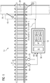
- FIG. 1 shows a railway track 10, which is crossed in the region of a crossing point 20 of a road 30 and there is equipped with a railway safety device 40 in the form of a railroad crossing.
- the railway safety system 40 and one or more sensors arranged on the railway track system 10 are connected to a track device 50.
- the track device 50 is connected to two sensors 60 and 70, of which the sensor 60 transmits a measurement result M1 and the sensor 70 transmits a measurement result M2 to the track device 50.
- the two sensors 60 and 70 detect along the direction of travel P - ie in the FIG. 1 From left to right - on the railway safety device 40 moving rail vehicle, for example by an axle detection of the passing rail vehicle, and pass a corresponding measurement result M1 or M2 to the track device 50 on.
- the two sensors 60 and 70 can transmit overrun events as such to the track device 50, or derived therefrom measurement results or other measurement results, in particular for example one or two of the following measurement results: the time interval between rail vehicles, the time cycle between rail vehicles, the absolute time, the Speed of the rail vehicle, the acceleration of the rail vehicle, the total number of axles of the rail vehicle, the axial spacing of the rail vehicle, the train length of the rail vehicle, the axle load of the rail vehicle, the number of traction units of the rail vehicle, the number of conductors on the overhead line of the rail vehicle and / or the traction energy of the rail vehicle.
- the route device 50 is equipped with a computer 51 and a memory 52.
- An operating program BP is stored in the memory 52 which, when executed by the computer 51, enables the track device 50 and causes it to control the railway safety system 40 and to determine a changeover point to the railway safety system 40 for this purpose.
- the switching time can be transmitted as such to the railway safety system 40, which subsequently generates the corresponding closing command for closing the railway safety system 40 on the basis of the received switching time; Alternatively, the switching time can be transmitted indirectly in the form of a control signal ST, which transmits the corresponding closing command itself to the railway safety system 40 at the switching time.
- identification records are stored, which uses the operating program BP for the operation of the railway safety system 40.
- two identification records which are identified by the reference numerals IDS1 and IDS2.
- Each of the two identification records IDS1 and IDS2 defines each a rule train, which is to be recognized by the route device and to be treated in a predetermined manner with respect to the switching time.
- auxiliary parameter values are stored in the memory 52, which in each case directly indicate the changeover point of the railway safety system 40 for a recognized control train or at least enable a determination of the changeover time on the basis thereof.
- auxiliary parameter set HW1 is assigned to the identification data record IDS1; this means that the auxiliary parameter set HW1 contains auxiliary parameter values for rail vehicles, which are detected by the identification data record IDS1. Accordingly, the auxiliary parameter set HW2 contains auxiliary parameter values for those rail vehicles which fall under the definition of the identification data record IDS2.
- identification data sets and auxiliary parameters for two control sequences are stored in the memory 52.
- the route device 50 is preferably operated as follows: If a rail vehicle passes the two sensors 60 and 70 as it travels along the direction of travel P, the corresponding measurement results M1 and M2 are sent to the route device 50.
- the operating program BP evaluates the measurement results M1 and M2 and checks whether the identification data sets IDS1 and IDS2 Allocate approaching rail vehicle one of the two identification records IDS1 or IDS2 leaves. If this is the case, the operating program BP concludes from this that the approaching rail vehicle is a control train which is to be treated in accordance with the auxiliary parameter set HW1 or HW2 associated with the identification data record.
- the approaching rail vehicle is a control train which is described by the identification data record IDS1 or is detected by it. Accordingly, the operating program BP will read the associated auxiliary parameter set HW1 from the memory 52 for the detected control train or for the identification data set IDS1 and determine the switching time for the railway safety system 40 on the basis of the auxiliary parameter values of the auxiliary parameter set HW1.
- the rule-specific auxiliary parameter sets HW1 and HW2 can include one or more quantitative variables that are to be taken into account quantitatively in the calculation of the switching time, for example, a fixed lead time, a fixed holding time at one or more breakpoints in front of the railway safety system, a standard acceleration for the rule train , a permitted maximum speed, etc.
- one or more identifiers may be stored in the auxiliary parameter sets HW1 and HW2 as rule-specific auxiliary parameter values that define the calculation formula when calculating the switchover time.
- an identifier "1" may indicate that the calculation of the switchover instant should be done without taking into account the train's currently measured acceleration of the train;
- An identifier "2" can indicate that the calculation of the switching time should be made taking into account the acceleration currently measured by the sensor.
- further identifiers for handling the respective rule can be defined.
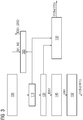
- FIG. 2 shows a first embodiment of an operating program BP, which in the memory 52 of the track device 50 according to FIG. 1 can be stored and is suitable for operation of the computer 51.
- an operating program BP which in the memory 52 of the track device 50 according to FIG. 1 can be stored and is suitable for operation of the computer 51.
- the operating program BP comprises a read-in module 100 for detecting the measurement results M1 and M2 according to FIG. 1 ,
- the read-in module 100 If the read-in module 100 has measurement results, it is checked in a subsequent test step 110 whether identification data records are present in the memory 52.
- a comparison step 120 is continued, in which the measurement results M1 and M2 are compared with the identification data sets IDS1 and IDS2.
- a standard activation step 130 is carried out, which performs the control of the railway safety system 40 with a standard switching time Tu (STD)) and, for example, a corresponding one Control signal ST (Tu (STD)) setting the standard switching time Tu (STD)) to the railway safety relay 40 according to FIG FIG. 1 transmitted.
- the standard switching time Tu (STD)) can be calculated, for example, by adding the transition time determined by the sensors 60 and 70 to a predetermined standard delay value.
- the comparison step 120 If, however, it is determined in the comparison step 120 that one of the two identification data sets, for example the identification data record IDS1, can be assigned to the measurement results M1 and M2, and thus it can be concluded that the approaching rail vehicle is a regulatory train according to the identification data record IDS1, then continued with a read-out step 140.
- one of the two identification data sets for example the identification data record IDS1
- the computer 51 reads from the memory 52 the auxiliary parameter set HW1, which is assigned to the identification data record IDS1.
- a subordinate control-individual control step 150 on the basis of the rule-specific auxiliary parameter values which are stored in the auxiliary parameter set HW1, the regular-individual changeover time for the railway safety system 40 is determined.
- the switching timing Tu (HW1)) or a corresponding control signal ST (Tu (HW1)) is formed and transmitted to the railway safety relay 40.
- the regular individual switching time Tu (HW1)) can be calculated for example by adding the determined by the sensors 60 and 70 Kochfahrzeitticians with a regelzugindividual delay value.
- FIG. 3 shows a second embodiment of an operating program BP, the control of the railway safety device 40 by the track device 50 according to FIG. 1 allows.
- the operating program BP according to FIG. 3 with respect to the program module 100, the checking step 110, the comparing step 120, the standard driving step 130, the reading step 140, and the rule-individual driving step 150 corresponds to the operation program BP according to FIG. 2 so, in this regard, the above explanations in connection with the FIG. 2 referenced.
- the operating program BP according to FIG. 3 has an additional data-set-forming module 160 which cooperates with the test step 110 and the read-in module 100.
- the program module BP works as follows: If it is determined in test step 110 that no identification data records are stored in memory 52 at all and, for this reason, a comparison with existing identification data sets can not take place, control of the railway safety system 40 is carried out in accordance with standard activation step 130, as described in connection with FIG FIG. 2 has been explained.
- the data set-forming module 160 is activated, which independently uses the data records M1, M2 of the read-in module 100 that are present on the input side, identification data sets, for example the identification data records IDS1 and IDS2 according to FIG FIG. 1 , generated.
- the record-forming module 160 uses the measurement results M1 and M2 to generate the identification data sets IDS1 and IDS2, preferably by checking whether the past approximation events in the case of a subset of rail vehicles are identical or at least sufficiently similar in accordance with a predetermined similarity threshold, in the case of a detected one Subset generated on the basis of the considered similar measurement results identification data for the identification record and the identification record using the generated identification data forms. A sufficient similarity of a subset of measurement results can be concluded, for example, if the measurement results of this subset do not deviate from the mean value of the respective subset beyond a predetermined extent.
- the data set-forming module 160 uses at least one of the above-mentioned types of measurement results as the measurement result M1 and M2.
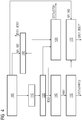
- FIG. 4 shows a third embodiment of an operating program BP
- the computer 51 of the track device 50 according to FIG. 1 can be executed to control the railway safety system 40.
- the program module BP according to FIG. 4 includes all program steps or program modules associated with the Figures 2 and 3 have already been explained; In this regard, reference is made to the above statements.
- a modification module 170 is provided, which cooperates with the comparison step 120 and the read-in module 100 and is configured to modify an identification data record identified in the context of the comparison step 120, for example the identification data record IDS1, as a function of the measurement results M1 and M2 currently acquired by the read-in module 100.
- a modified modification data record IDS1 ' is generated, which is stored in the memory 52 as a replacement for the previously stored earlier identification data record IDS1 there.
- the modified identification data set IDS1 ' replaces the earlier identification data set IDS1, which is stored in the FIG. 1 is shown.
- a more narrowly defined identification data record can be formed, in particular if the measurement results measured during approach events in the past show that rail vehicles that are detected by the identification data record and recognized as a corresponding control code also depend on the more narrowly defined identification data record would be recorded.
- a modification of the identification data record IDS1 is also advantageous if the measurement results measured during approach events in the past show that rail vehicles that are detected by the predefined identification data record and recognized as the same rule train are assigned to different subgroups of rule trains can.
- sub-data records can be generated within the identification data record IDS1, or the existing identification data record IDS1 can be replaced by two new identification data records which are stored in the identification data record IDS1 FIG. 4 are denoted by the reference character IDS1 'and IDS''.
Landscapes
- Engineering & Computer Science (AREA)
- Mechanical Engineering (AREA)
- Automation & Control Theory (AREA)
- Train Traffic Observation, Control, And Security (AREA)
- Electric Propulsion And Braking For Vehicles (AREA)
Applications Claiming Priority (1)
| Application Number | Priority Date | Filing Date | Title |
|---|---|---|---|
| DE102018206304.4A DE102018206304A1 (de) | 2018-04-24 | 2018-04-24 | Verfahren zur Ansteuerung einer Eisenbahnsicherungsanlage |
Publications (4)
| Publication Number | Publication Date |
|---|---|
| EP3560792A2 true EP3560792A2 (fr) | 2019-10-30 |
| EP3560792A3 EP3560792A3 (fr) | 2020-03-04 |
| EP3560792C0 EP3560792C0 (fr) | 2025-10-29 |
| EP3560792B1 EP3560792B1 (fr) | 2025-10-29 |
Family
ID=66041182
Family Applications (1)
| Application Number | Title | Priority Date | Filing Date |
|---|---|---|---|
| EP19166128.9A Active EP3560792B1 (fr) | 2018-04-24 | 2019-03-29 | Procédé de commande d'une installation de sécurité ferroviaire |
Country Status (2)
| Country | Link |
|---|---|
| EP (1) | EP3560792B1 (fr) |
| DE (1) | DE102018206304A1 (fr) |
Cited By (1)
| Publication number | Priority date | Publication date | Assignee | Title |
|---|---|---|---|---|
| CN116039735A (zh) * | 2022-12-25 | 2023-05-02 | 卡斯柯信号有限公司 | 一种zc边界列车序列一致性判断方法、设备及介质 |
Citations (1)
| Publication number | Priority date | Publication date | Assignee | Title |
|---|---|---|---|---|
| EP2718168B1 (fr) * | 2011-07-14 | 2017-06-14 | Siemens Aktiengesellschaft | Procédé d'exploitation d'un équipement de sécurité ferroviaire et équipement de sécurité ferroviaire |
Family Cites Families (3)
| Publication number | Priority date | Publication date | Assignee | Title |
|---|---|---|---|---|
| DE10227046C1 (de) * | 2002-06-17 | 2003-07-03 | Bahn Deutsche | Geschwindigkeitsabhängige Absicherung von Gefahrenbereichen |
| DE102009019302A1 (de) * | 2009-04-24 | 2010-10-28 | Siemens Aktiengesellschaft | Verfahren und Vorrichtung zur Steuerung von Eisenbahnsicherungssystemen |
| DE102015203681A1 (de) * | 2015-03-02 | 2016-09-22 | Siemens Aktiengesellschaft | Verfahren und Vorrichtung zur Zugarterkennung |
-
2018
- 2018-04-24 DE DE102018206304.4A patent/DE102018206304A1/de not_active Withdrawn
-
2019
- 2019-03-29 EP EP19166128.9A patent/EP3560792B1/fr active Active
Patent Citations (1)
| Publication number | Priority date | Publication date | Assignee | Title |
|---|---|---|---|---|
| EP2718168B1 (fr) * | 2011-07-14 | 2017-06-14 | Siemens Aktiengesellschaft | Procédé d'exploitation d'un équipement de sécurité ferroviaire et équipement de sécurité ferroviaire |
Cited By (1)
| Publication number | Priority date | Publication date | Assignee | Title |
|---|---|---|---|---|
| CN116039735A (zh) * | 2022-12-25 | 2023-05-02 | 卡斯柯信号有限公司 | 一种zc边界列车序列一致性判断方法、设备及介质 |
Also Published As
| Publication number | Publication date |
|---|---|
| EP3560792A3 (fr) | 2020-03-04 |
| DE102018206304A1 (de) | 2019-10-24 |
| EP3560792C0 (fr) | 2025-10-29 |
| EP3560792B1 (fr) | 2025-10-29 |
Similar Documents
| Publication | Publication Date | Title |
|---|---|---|
| EP3787950B1 (fr) | Procédé et dispositif de détection de véhicules suivant un véhicule | |
| EP3374246B1 (fr) | Procédé et dispositif de détection de déraillement commandée par comparaison | |
| EP1977950A2 (fr) | Procédé destiné à l'évaluation en fonction de l'effet de la qualité de stockage d'une voie | |
| DE19953677C1 (de) | Verfahren und Vorrichtung zur Erkennung einer Entgleisung eines spurgebundenen Fahrzeugs | |
| WO2014040892A2 (fr) | Fonctionnement d'un véhicule ferroviaire au moyen d'un dispositif etcs | |
| EP3464000B1 (fr) | Procédé et dispositif de vérification automatique de freins d'un véhicule guidé | |
| DE102017108034A1 (de) | Verfahren und Vorrichtung zum automatischen Feststellen einer Beladungsänderung eines Kraftfahrzeugs und Kraftfahrzeug | |
| EP3458331B1 (fr) | Procédé et dispositif de surveillance d'au moins un composant de voie posé dans la construction de chemin de fer | |
| WO2001081147A1 (fr) | Procede de surveillance de caracteristiques de deplacement d'un vehicule sur rail | |
| EP3560792B1 (fr) | Procédé de commande d'une installation de sécurité ferroviaire | |
| EP3419879B1 (fr) | Procédé et dispositif pour déterminer une puissance de freinage sûre d'un véhicule ferroviaire | |
| WO2015090933A1 (fr) | Commande de véhicule ferroviaire | |
| EP1165355A1 (fr) | Procede et dispositif pour surveiller un vehicule | |
| DE102016125196A1 (de) | Verfahren zur Entgleisungsdetektion anhand von Raddrehzahlsignalen | |
| EP3988422B1 (fr) | Procédé et dispositif de détection d'un état de déraillement d'un véhicule ferroviaire, ainsi que véhicule ferroviaire | |
| EP3823876B1 (fr) | Procédé et système de reconnaissance d'une roue de véhicule ferroviaire | |
| EP0810941B1 (fr) | Procede d'actualisation de valeurs de substitution pour une caracteristique determinant le roulement de wagons d'une installation de triage | |
| DE10153447A1 (de) | Verfahren und Vorrichtung zur Programmierung eines Steuergeräts eines Fahrzeugs, insbesondere eines Kraftfahrzeugs | |
| EP2718167B1 (fr) | Procédé et dispositif de commande pour déterminer la longueur d'au moins une section de voie | |
| DE102016225276A1 (de) | Verfahren zum Kalibrieren eines Radsensors sowie entsprechender Radsensor | |
| EP0551972B1 (fr) | Dispositif de commande de train pour les chemins de fer | |
| DE102016209259A1 (de) | Verfahren zur Ermittlung einer Zuggattung, eine Vorrichtung zur Erkennung einer Zuggattung, Steuerungssystem | |
| DE102008026572A1 (de) | Verfahren und Anordnung zur Überwachung des Belegungszustandes eines Gleisabschnitts | |
| EP4240623B1 (fr) | Dispositif de contrôle | |
| DE102023200761A1 (de) | Verfahren und Einrichtung zum Erzeugen eines einen Zustand eines Fahrzeugs anzeigenden Zustandssignals |
Legal Events
| Date | Code | Title | Description |
|---|---|---|---|
| PUAI | Public reference made under article 153(3) epc to a published international application that has entered the european phase |
Free format text: ORIGINAL CODE: 0009012 |
|
| STAA | Information on the status of an ep patent application or granted ep patent |
Free format text: STATUS: THE APPLICATION HAS BEEN PUBLISHED |
|
| AK | Designated contracting states |
Kind code of ref document: A2 Designated state(s): AL AT BE BG CH CY CZ DE DK EE ES FI FR GB GR HR HU IE IS IT LI LT LU LV MC MK MT NL NO PL PT RO RS SE SI SK SM TR |
|
| AX | Request for extension of the european patent |
Extension state: BA ME |
|
| RIC1 | Information provided on ipc code assigned before grant |
Ipc: B61L 1/02 20060101AFI20191016BHEP Ipc: B61L 29/32 20060101ALI20191016BHEP Ipc: B61L 1/16 20060101ALN20191016BHEP Ipc: B61L 25/04 20060101ALI20191016BHEP Ipc: B61L 29/22 20060101ALN20191016BHEP |
|
| PUAL | Search report despatched |
Free format text: ORIGINAL CODE: 0009013 |
|
| AK | Designated contracting states |
Kind code of ref document: A3 Designated state(s): AL AT BE BG CH CY CZ DE DK EE ES FI FR GB GR HR HU IE IS IT LI LT LU LV MC MK MT NL NO PL PT RO RS SE SI SK SM TR |
|
| AX | Request for extension of the european patent |
Extension state: BA ME |
|
| RIC1 | Information provided on ipc code assigned before grant |
Ipc: B61L 29/22 20060101ALN20200127BHEP Ipc: B61L 1/16 20060101ALN20200127BHEP Ipc: B61L 25/04 20060101ALI20200127BHEP Ipc: B61L 1/02 20060101AFI20200127BHEP Ipc: B61L 29/32 20060101ALI20200127BHEP |
|
| STAA | Information on the status of an ep patent application or granted ep patent |
Free format text: STATUS: REQUEST FOR EXAMINATION WAS MADE |
|
| 17P | Request for examination filed |
Effective date: 20200901 |
|
| RBV | Designated contracting states (corrected) |
Designated state(s): AL AT BE BG CH CY CZ DE DK EE ES FI FR GB GR HR HU IE IS IT LI LT LU LV MC MK MT NL NO PL PT RO RS SE SI SK SM TR |
|
| STAA | Information on the status of an ep patent application or granted ep patent |
Free format text: STATUS: EXAMINATION IS IN PROGRESS |
|
| 17Q | First examination report despatched |
Effective date: 20220214 |
|
| GRAP | Despatch of communication of intention to grant a patent |
Free format text: ORIGINAL CODE: EPIDOSNIGR1 |
|
| STAA | Information on the status of an ep patent application or granted ep patent |
Free format text: STATUS: GRANT OF PATENT IS INTENDED |
|
| RIC1 | Information provided on ipc code assigned before grant |
Ipc: B61L 29/22 20060101ALN20250523BHEP Ipc: B61L 1/16 20060101ALN20250523BHEP Ipc: B61L 29/32 20060101ALI20250523BHEP Ipc: B61L 25/04 20060101ALI20250523BHEP Ipc: B61L 1/02 20060101AFI20250523BHEP |
|
| RIC1 | Information provided on ipc code assigned before grant |
Ipc: B61L 29/22 20060101ALN20250604BHEP Ipc: B61L 1/16 20060101ALN20250604BHEP Ipc: B61L 29/32 20060101ALI20250604BHEP Ipc: B61L 25/04 20060101ALI20250604BHEP Ipc: B61L 1/02 20060101AFI20250604BHEP |
|
| INTG | Intention to grant announced |
Effective date: 20250612 |
|
| GRAS | Grant fee paid |
Free format text: ORIGINAL CODE: EPIDOSNIGR3 |
|
| GRAA | (expected) grant |
Free format text: ORIGINAL CODE: 0009210 |
|
| STAA | Information on the status of an ep patent application or granted ep patent |
Free format text: STATUS: THE PATENT HAS BEEN GRANTED |
|
| RAP3 | Party data changed (applicant data changed or rights of an application transferred) |
Owner name: SIEMENS MOBILITY GMBH |
|
| AK | Designated contracting states |
Kind code of ref document: B1 Designated state(s): AL AT BE BG CH CY CZ DE DK EE ES FI FR GB GR HR HU IE IS IT LI LT LU LV MC MK MT NL NO PL PT RO RS SE SI SK SM TR |
|
| REG | Reference to a national code |
Ref country code: CH Ref legal event code: F10 Free format text: ST27 STATUS EVENT CODE: U-0-0-F10-F00 (AS PROVIDED BY THE NATIONAL OFFICE) Effective date: 20251029 Ref country code: GB Ref legal event code: FG4D Free format text: NOT ENGLISH |
|
| REG | Reference to a national code |
Ref country code: DE Ref legal event code: R096 Ref document number: 502019014023 Country of ref document: DE |
|
| REG | Reference to a national code |
Ref country code: IE Ref legal event code: FG4D Free format text: LANGUAGE OF EP DOCUMENT: GERMAN |
|
| REG | Reference to a national code |
Ref country code: CH Ref legal event code: R17 Free format text: ST27 STATUS EVENT CODE: U-0-0-R10-R17 (AS PROVIDED BY THE NATIONAL OFFICE) Effective date: 20251217 |
|
| U01 | Request for unitary effect filed |
Effective date: 20251125 |
|
| U07 | Unitary effect registered |
Designated state(s): AT BE BG DE DK EE FI FR IT LT LU LV MT NL PT RO SE SI Effective date: 20251128 |