EP3562417B1 - Instrumentation de compression d'articulation - Google Patents
Instrumentation de compression d'articulation Download PDFInfo
- Publication number
- EP3562417B1 EP3562417B1 EP17838106.7A EP17838106A EP3562417B1 EP 3562417 B1 EP3562417 B1 EP 3562417B1 EP 17838106 A EP17838106 A EP 17838106A EP 3562417 B1 EP3562417 B1 EP 3562417B1
- Authority
- EP
- European Patent Office
- Prior art keywords
- implant
- compression
- slot
- shaft
- patient
- Prior art date
- Legal status (The legal status is an assumption and is not a legal conclusion. Google has not performed a legal analysis and makes no representation as to the accuracy of the status listed.)
- Active
Links
Images








Classifications
-
- A—HUMAN NECESSITIES
- A61—MEDICAL OR VETERINARY SCIENCE; HYGIENE
- A61B—DIAGNOSIS; SURGERY; IDENTIFICATION
- A61B17/00—Surgical instruments, devices or methods
- A61B17/56—Surgical instruments or methods for treatment of bones or joints; Devices specially adapted therefor
- A61B17/58—Surgical instruments or methods for treatment of bones or joints; Devices specially adapted therefor for osteosynthesis, e.g. bone plates, screws or setting implements
- A61B17/68—Internal fixation devices, including fasteners and spinal fixators, even if a part thereof projects from the skin
- A61B17/72—Intramedullary devices, e.g. pins or nails
- A61B17/7216—Intramedullary devices, e.g. pins or nails for bone lengthening or compression
- A61B17/7225—Intramedullary devices, e.g. pins or nails for bone lengthening or compression for bone compression
-
- A—HUMAN NECESSITIES
- A61—MEDICAL OR VETERINARY SCIENCE; HYGIENE
- A61B—DIAGNOSIS; SURGERY; IDENTIFICATION
- A61B17/00—Surgical instruments, devices or methods
- A61B17/56—Surgical instruments or methods for treatment of bones or joints; Devices specially adapted therefor
- A61B17/58—Surgical instruments or methods for treatment of bones or joints; Devices specially adapted therefor for osteosynthesis, e.g. bone plates, screws or setting implements
- A61B17/68—Internal fixation devices, including fasteners and spinal fixators, even if a part thereof projects from the skin
- A61B17/72—Intramedullary devices, e.g. pins or nails
- A61B17/7291—Intramedullary devices, e.g. pins or nails for small bones, e.g. in the foot, ankle, hand or wrist
-
- A—HUMAN NECESSITIES
- A61—MEDICAL OR VETERINARY SCIENCE; HYGIENE
- A61B—DIAGNOSIS; SURGERY; IDENTIFICATION
- A61B17/00—Surgical instruments, devices or methods
- A61B17/56—Surgical instruments or methods for treatment of bones or joints; Devices specially adapted therefor
- A61B17/58—Surgical instruments or methods for treatment of bones or joints; Devices specially adapted therefor for osteosynthesis, e.g. bone plates, screws or setting implements
- A61B17/68—Internal fixation devices, including fasteners and spinal fixators, even if a part thereof projects from the skin
- A61B17/84—Fasteners therefor or fasteners being internal fixation devices
- A61B17/86—Pins or screws or threaded wires; nuts therefor
- A61B17/8665—Nuts
-
- A—HUMAN NECESSITIES
- A61—MEDICAL OR VETERINARY SCIENCE; HYGIENE
- A61B—DIAGNOSIS; SURGERY; IDENTIFICATION
- A61B17/00—Surgical instruments, devices or methods
- A61B17/56—Surgical instruments or methods for treatment of bones or joints; Devices specially adapted therefor
- A61B17/58—Surgical instruments or methods for treatment of bones or joints; Devices specially adapted therefor for osteosynthesis, e.g. bone plates, screws or setting implements
- A61B17/88—Osteosynthesis instruments; Methods or means for implanting or extracting internal or external fixation devices
- A61B17/8866—Osteosynthesis instruments; Methods or means for implanting or extracting internal or external fixation devices for gripping or pushing bones, e.g. approximators
-
- A—HUMAN NECESSITIES
- A61—MEDICAL OR VETERINARY SCIENCE; HYGIENE
- A61B—DIAGNOSIS; SURGERY; IDENTIFICATION
- A61B17/00—Surgical instruments, devices or methods
- A61B17/56—Surgical instruments or methods for treatment of bones or joints; Devices specially adapted therefor
- A61B17/58—Surgical instruments or methods for treatment of bones or joints; Devices specially adapted therefor for osteosynthesis, e.g. bone plates, screws or setting implements
- A61B17/68—Internal fixation devices, including fasteners and spinal fixators, even if a part thereof projects from the skin
- A61B17/72—Intramedullary devices, e.g. pins or nails
- A61B17/7233—Intramedullary devices, e.g. pins or nails with special means of locking the nail to the bone
-
- A—HUMAN NECESSITIES
- A61—MEDICAL OR VETERINARY SCIENCE; HYGIENE
- A61B—DIAGNOSIS; SURGERY; IDENTIFICATION
- A61B17/00—Surgical instruments, devices or methods
- A61B17/56—Surgical instruments or methods for treatment of bones or joints; Devices specially adapted therefor
- A61B17/58—Surgical instruments or methods for treatment of bones or joints; Devices specially adapted therefor for osteosynthesis, e.g. bone plates, screws or setting implements
- A61B17/88—Osteosynthesis instruments; Methods or means for implanting or extracting internal or external fixation devices
- A61B17/8872—Instruments for putting said fixation devices against or away from the bone
-
- A—HUMAN NECESSITIES
- A61—MEDICAL OR VETERINARY SCIENCE; HYGIENE
- A61B—DIAGNOSIS; SURGERY; IDENTIFICATION
- A61B17/00—Surgical instruments, devices or methods
- A61B2017/00982—General structural features
- A61B2017/00991—Telescopic means
Definitions
- the present disclosure relates to surgical implant systems, including implants and instruments. Specifically, the present disclosure relates to intramedullary devices, and instruments.
- Intramedullary implants are used in various contexts, including to repair fractures or to achieve joint fusion (i.e., arthrodesis).
- US 2012/330313A describes an intramedullary nail for internal fixation.
- arthrodesis it is frequently necessary to apply compression across one or more joints to bring the adjoining bones of the joint into apposition, and then fix the adjoining bones so that fusion can occur across the joint site.
- An intramedullary implant can be used to achieve fixation of adjoining bones of a joint after compression and secure the bones in position to allow fusion to occur. Yet, in a number of cases, compression of the joint structures occurs externally of the intramedullary device.
- 9,308,031 discloses a compression instrument that contacts the patient's foot externally and applies pressure to the patient's calcaneus externally to bring the calcaneal bone into apposition against the patient's talus.
- the present disclosure provides intramedullary implants and instruments, that allow for internal compression across various joints, as described in more detail below.
- the present invention provides an ankle arthrodesis implant as defined in claim 1, comprising an elongate shaft sized and shaped to be implanted in an intramedullary canal of a tibia of a patient, the elongate shaft having an internal bore, a first angled opening through the shaft, the first angled opening defining a first axis that extends through the tibia and into a talus bone of the patient across a tibio-talar joint when the implant is implanted, a first elongate slot through the shaft, the first elongate slot defining a second axis that extends into the patient's talus when the implant is implanted, the first elongate slot being configured to allow a first fixation member to translate axially relative to the shaft within the first slot from a first position to a second different position to compress a tibio-talar joint, a second elongate slot through the shaft, the second elongate slot defining a third axis
- the internal bore of the ankle arthrodesis implant can be threaded.
- the invention also provides an implant system comprising the ankle arthrodesis implant and first, second, third, and fourth fixation members each defining a diameter, wherein the first and second elongate slots each has a length that is anywhere between about 125-500% of the diameter of the second and third fixation members, and a width that is substantially equal to or under 120% of the diameter of the second and third fixation members, respectively.
- the implant system can further comprise a telescoping clamp having a body defining a first area shaped to engage the first fixation member, wherein the telescoping clamp is disposable in the internal bore of the implant adjacent the first slot and is movable within the internal bore, with the first fixation member in the first slot, so that the first area of the body of the telescoping clamp engages the shaft of the first fixation member and moves the first fixation member from a first position in the first slot to a second different position.
- a telescoping clamp having a body defining a first area shaped to engage the first fixation member, wherein the telescoping clamp is disposable in the internal bore of the implant adjacent the first slot and is movable within the internal bore, with the first fixation member in the first slot, so that the first area of the body of the telescoping clamp engages the shaft of the first fixation member and moves the first fixation member from a first position in the first slot to a second different position.
- the implant or implant system can further comprise a third angled opening through the shaft, the third angled opening defining a fourth axis that extends through the calcaneus and into a talus bone of the patient across the subtalar joint when the implant is implanted.
- an intramedullary implant comprising implanting an intramedullary implant into an intramedullary canal of a bone, the intramedullary implant having a shaft and an internal bore, inserting a first fixation member into a first elongate slot extending through the shaft and into bone, inserting a second fixation member into a second elongate slot extending through the shaft and into bone, subsequently engaging the first fixation member internally within the internal bore with a first telescoping member to move the first fixation member within the first elongate slot from a first position to a second different position, and engaging the second fixation member internally within the internal bore with a second telescoping member to move the second fixation member within the second elongate slot from a first position to a second position.
- anterior and posterior mean nearer the front or nearer the rear of the body, respectively; proximal and distal mean nearer to or further from the root of a structure, respectively; and medial and lateral mean nearer the sagittal plane or further from the sagittal plane, respectively.
- the sagittal plane is an imaginary vertical plane through the middle of the body or body structure that divides the body or body structure into right and left halves.
- implant and prosthesis and variations thereof, can be used interchangeably.
- the present disclosure is directed to intramedullary implants and compression instruments that provide for compression of bone parts or bones adjoining a joint internally through the intramedullary implant. In this way, a simpler and more-effective compression technique can be carried out, which removes deficiencies associated with other compression techniques or methods.
- an intramedullary implant 10 is shown in the form of an intramedullary nail (e.g., an IM ankle nail).
- Fig. 1 also illustrates a jig nose 60 and a compression instrument 90 attachable to jig nose 60 for applying compression across bone parts or bones adjoining a joint internally through implant 10.
- implant 10, jig nose 60, and compression instrument 90 attachable to compress bones adjoining a joint together, although it is equally contemplated that such implants and instruments can instead be used to compress bone fragments or parts together (e.g., in the case of repairing a fracture).
- Implant 10 can have a shaft 12 with a bend 11 between a proximal section of shaft 12 and a distal section of shaft 12. Bend 11 can be anywhere between about two degrees to about fifteen degrees (2-15°), in another example anywhere between about five degrees to about ten degrees (5-10°), or in yet another example about five degrees (5°).
- the proximal section of shaft 12 can define an axis 21 and the distal section of shaft 12 can define an axis 23, and the axes 21, 23 can intersect to form any of the aforementioned angles.
- Implant 10 can also include a set of distal openings 14, 16, 18, 20 for receiving bone screws 52, as shown in Figs. 9A-C .
- Openings 14, 16, 18, 20 can be threaded or unthreaded, in any combination. Openings 14, 16, 18, 20 can also be arranged substantially perpendicular to axis 23, in an example, or any of openings 14, 16, 18, 20 can be a slot similar to first slot 24 described below.
- Implant 10 further includes a first angled opening 22 through shaft 12 at the proximal section of shaft 12.
- opening 22 can be angled through shaft 12 proximally by between about thirty five degrees to about fifty degrees (35-50°), or alternatively about forty five degrees (45°) proximally relative to axis 21.
- Opening 22 can also be angled approximately anywhere between about twenty degrees to about thirty degrees (20-30°), in an example about twenty eight degrees (28°), medially relative to a sagittal plane 41 extending through the patient's ankle, as illustrated in Fig. 9C . As shown in Figs.
- this can create a situation in which a bone screw 53 can be inserted downwardly through opening 22 and into a patient's tibia 40 and talus 44.
- screw 53 is approximately sixty two and a half millimeters (62.5mm) in length and can extend into tibia 40 and talus 44 when inserted through opening 22.
- screw 53 can be of a different length and also extend into the patient's navicular 49 - i.e ., through tibia 40, talus 44, and into navicular 49.
- an imaginary central axis of opening 22 can extend and/or project through tibia 40, talus 44, and navicular 49 (e.g., so that a certain size screw can extend into the foregoing bones, depending upon its length).
- Implant 10 includes a first slot 24 that is elongated along axis 21.
- Slot 24 can have a width that is approximately the same as a bone screw 54 and a length that is greater than the width, in an example a length that is anywhere between about one-hundred and twenty five percent to four hundred percent (125-400%) of the diameter of bone screw 54.
- slot 24 can have a length that is approximately fourteen and three-quarter millimeters (14.75mm) and a width that is approximately six millimeters (6mm).
- the elongate length of slot 24 can allow bone screw 54 to move longitudinally within slot 24 by anywhere between about two millimeters to about ten millimeters (2-10mm), in an example about seven millimeters (7mm).
- a central axis of slot 24 can be angled medially relative to sagittal plane 41 by anywhere between about thirty degrees to about sixty degrees (30-60°), in an example by about fifty degrees (50°). This creates a situation in which screw 54 inserted through slot 24 extends along the same medial angle as slot 24.
- Implant 10 also has a second angled opening 26 extending through shaft 12, which can be arranged proximally of slot 24.
- Opening 26 can be angled distally relative to axis 21 by anywhere between about twenty degrees to about thirty five degrees (20-35°), in an example about twenty five degrees (25°).
- opening 26 can be angled medially relative to sagittal plane 41, as shown in Fig. 9C , by anywhere between about ten degrees to about twenty five degrees (10-25°), in an example about thirteen degrees (13°).
- this can create a situation in which a screw 55 inserted through opening 26 can extend through a patient's calcaneus 46 and into the patient's talus 44.
- screw 55 can be anywhere between about thirty millimeters to about sixty millimeters (30-60mm) in length, in a specific example about forty eight millimeters (48mm).
- a second slot 28 is disposed through shaft 12 of implant 10, as shown in Fig. 10B .
- Slot 28 can have a width that is approximately the same as a bone screw 56 and a length that is greater than the width, in an example a length that is anywhere between about one-hundred and twenty five percent to four hundred percent (125-400%) of the diameter of bone screw 56.
- slot 28 can have a length that is approximately eleven and three-quarter millimeters (11.75mm) and a width that is approximately six millimeters (6mm).
- the elongate length of slot 28 can allow bone screw 56 to move longitudinally within slot 28 by anywhere between about two millimeters to about ten millimeters (2-10mm), in an example about four millimeters (4mm).
- screw 56 can act to compress a patient's calcaneus 46 against the patient's talus 44.
- a central axis of slot 28 can extend roughly perpendicular or alternatively transverse to sagittal plane 41 so that screw 56 can extend through calcaneus 46 in a medial-to-lateral direction.
- screw 56 can be anywhere between about fifteen millimeters to about twenty five millimeters (15-25mm) in length, in a specific example about sixteen and a half to about twenty and a half millimeters (16.5-20.5mm) in length.
- Implant 10 can further include a final angled opening 30.
- Opening 30 can be angled distally relative to axis 21 by anywhere between about two degrees to about fifteen degrees (2-15°), in an example about five degrees (5°).
- opening 30 can be angled laterally relative to sagittal plane 41 by anywhere between about two degrees to about fifteen degrees (2-15°), in an example about five degrees (5°). As shown in Figs. 9A-C , this can create a situation in which a screw 57 inserted into opening 30 extends upwards and laterally by the above angle amounts in the patient's calcaneus 46.
- screw 57 can be anywhere between about fifty millimeters to about ninety millimeters (50-90mm) in length, in a specific example seventy five millimeters (75mm) in length. In another example, screw 57 can be of a sufficient length to extend through calcaneus 46 and into a patient's cuboid across the calcaneus-cuboid joint.
- implant 10 is hollow, such that a bore 32 extends through shaft 12.
- Bore 32 can define a first distal bore part 35 and a second proximal bore part 36, where the diameter of proximal bore part 36 can be greater than that of distal bore part 35. This difference in diameters can act to create a transition zone or taper 37 between bore parts 35, 36.
- a portion or all of proximal bore part 36 can be threaded 34.
- threading 34 can extend from a proximal end of proximal bore part 36 and encompass part or all of the walls defining proximal bore part 36 along the extent of first slot 24.
- threading 34 can extend along part or all of the walls defining proximal bore part 36 along the extent of second slot 28. As describe in more detail subsequently, such threading 34 can be used with CoreLock TM Technology, developed by Biomet, Inc.
- CoreLock TM Technology is exemplified in the ⁇ 031 Patent discussed above.
- CoreLock TM Technology Applicant is referring to any of the telescopic clamps, securing devices, locking devices, and/or compression devices disclosed in the ⁇ 031 Patent, for example securing devices 200 (see e.g., Fig. 16), 700 (see e.g., Figs. 25-26), and 900 (see e.g., Figs. 34-35) and locking device 1030 (see e.g., Figs. 44-44A) and compression device 1024 ( see e.g ., Figs. 45-45A).
- securing devices 200 see e.g., Fig. 16
- 700 see e.g., Figs. 25-26
- 900 see e.g., Figs. 34-35
- locking device 1030 see e.g., Figs. 44-44A
- compression device 1024 see e.
- implant 10 can have characteristics that make it suitable for use with such securing, locking, and compression devices.
- a portion of bore 32 - e.g ., proximal bore part 36 - can be keyed as is described with reference to, amongst other areas, Figs. 47A-47B of the ⁇ 031 Patent.
- a portion of longitudinal bore 1006 of IM implant 1002 can be keyed as at 1020, 1022 so as to key with second component 1078 of locking device 1030 and/or second component 1076 of compression device 1024.
- first components 1050, 1046 of the locking and compression devices 1030, 1024 can be rotated relative to second components 1078, 1076 and, by virtue of the threaded interaction between first components 1050, 1046 and the IM longitudinal bore 1006, locking and compression devices 1030, 1024 can be moved longitudinally relative to the IM implant.
- Such movement can cause screws associated with the respective securing, compression, or locking device to be secured, compressed in a particular direction within a slot of the IM implant, or locked, respectively.
- Applicant contemplates that such mechanisms can be used herein to lock and/or cause translation of any of screws 53-57 within openings 22, 26, 30 and slots 24, 28.
- Certain examples from the ⁇ 031 Patent might be used for simplicity's sake, but it is to be understood that any of the securing, locking, and/or compression devices of the ⁇ 031 Patent can be used with implant 10 and the instrumentation described herein.
- first components 1050, 1046 of locking and compression devices 1030, 1024 can further include generally similar features, and are also described in detail in U.S. Patent No. 8,303,590 ("'590 Patent"), filed Jan. 26, 2007 .
- '590 Patent The use of the aforementioned securing, locking, and/or compression devices of the ⁇ 031 Patent will, for the moment, be set aside but revisited in the disclosure below.
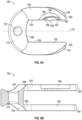
- a jig nose 60 is illustrated therein.
- Jig nose 60 can be attachable to implant 10, as shown in Fig. 1 , via one or more protrusions 64 on a distal section of a shaft 62 of jig nose 60.
- one or more recesses can be used instead of protrusions.
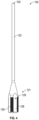
- Jig nose 60 can have a body 70 with shaft 62 extending from body 70.
- Shaft 62 can have threaded sections 66 and substantially-flat sections 68. In an example, two to four or more threaded sections 66 can be included on shaft 62, as well as two to four or more substantially-flat sections 68.
- Threaded sections 66 can be curved along a cross-sectional direction of shaft 62 so that, collectively, threaded sections 66 can define a somewhat cylindrically-threaded shape. As described below, this is so that shaft 62 can interact with a threaded portion of an externally-mounted compression nut, similar to compression nut 1124 of the ⁇ 031 Patent.
- jig nose 60 can be configured for internal compression as described below, jig nose 60 can also be used with externally-mounted compression instruments, such as compression nut 1124 of the ⁇ 031 Patent, if needed (e.g., to augment internal compression).
- Jig nose 60 can also include a lumen 72 through body 70 and shaft 62, and openings or cutouts 74 in a proximal section of body 70. Cutouts 74 can extend through body 70 and open into lumen 72, in an example, or cutouts 74 can extend only partway through body 70. In the latter case, cutouts 74 can define a floor surface that separates lumen 72 from cutouts 74. In an example, two cutouts 74 can be provided, which are separated by a solid section 76 of body 70. Cutouts 74 can be defined by first and second flanges 75, 77 that are separated by a distance that is equal to or slightly greater than a thickness of arms 154 of horseshoe 150, described more fully below.
- a proximal face of jig nose 60 can also include one or more recesses 78, and by way of example two recesses 78 are shown in Fig. 2B .
- Fig. 3 is a perspective view of a compression nut 100 of compression instrument 90.
- Compression nut 90 can have a shaft 102 and a body 104.
- Shaft 102 in an example, can have a section shaped to engage with a mating portion of a driving tool, such as a female portion or socket of a T-handle or a straight handle.
- a driving tool such as a female portion or socket of a T-handle or a straight handle.
- a portion of body 104 of compression nut 100 can also be polygonal-shaped, in an example hexagonally shaped.
- An outer flange 106 can extend from body 104, and next to outer flange 106 can be a projection 108 that can be, in an example, cylindrically shaped.
- a groove 110 can extend into projection 108 about part or all of its circumference.
- compression nut 100 can have a hollow threaded bore 112 that is internally threaded.
- Compression post 120 can include a shaft 122 and a threaded body 121 that can be received in threaded bore 112 of compression nut 100.
- Body 121 can have threaded sections 126 and substantially flat sections 128 arranged about its circumference.
- four curved or flat threaded sections 126 can be defined around body 121's circumference that, collectively, define a somewhat cylindrically-threaded shape.
- a distance between diametrically-opposite threaded sections 126 can be approximately equal to the inner diameter of hollow threaded bore 112 of compression nut 100. More or fewer threaded sections 126 can be included on body 121.
- substantially flat sections 128 can be included on body 121.
- Flat sections 128 can collectively define a polygonal-shape, in an example a somewhat square or rectangular shape.
- a distance between diametrically-opposite flat sections 128 can be approximately equal to the diameter of bore 146 of anti-rotation frame 130, discussed below.
- More or fewer flat sections 128 can be included on body 121.
- a distal end of shaft 122 of compression post 120 can also be curved as at 124 or otherwise shaped so that distal end 124 can engage with the shaft of a bone screw for compression purposes.
- distal end 124 can form a partially circular or hemi-circular shape, distal end 124 can be concave, or distal end 124 can be concave in perpendicular directions.
- Compression post 120 can also have one or more openings 129, and in an example a pair of openings 129, for receiving a pin(s) 137 ( see e.g ., Fig. 1 ).
- Anti-rotation frame 130 can include a body 132 with a bore 139 that can define a first bore part 140 and a second bore part 146 (see e.g., Figs. 5B-C ).
- first bore part 140 can be cylindrical in shape
- second bore part 146 can be polygonal in shape, and in a specific example, square or rectangular.
- Second bore part 146 can alternatively take any non-rotational shape, such as oval, rounded with lobes, keyed, triangular, etc.
- First bore part 140 can have a diameter that is about equal to or alternatively slightly greater than an outer diameter of projection 108 of compression nut 100, and second bore part 146 can have an opening dimension or effective diameter that is equal to or alternatively slightly greater than a cross-sectional dimension or an effective diameter of body 121 of compression post 120, taken at flat sections 128.
- Anti-rotation frame 130 can further include one or more openings 134, and in an example a pair of openings 134, which can extend through body 132 into first bore part 140. Openings 134 can receive pins 135, as shown in Fig. 1 .
- body 132 can include one or more slots 136, and in an example a pair of slots 136, and distance gauge markings 138. Slot(s) 136 can be sized to receive a pin 137, as shown in Fig. 1 .
- a flange 142 can extend outwards from body 132 of anti-rotation frame 130 and define an outer diameter that is larger than the diameter of lumen 72 through jig nose 60.
- a set of posts 144 can also extend from flange 142 or body 132 and engage with recesses 78 of jig nose 60.
- Flange 142 can further include features to engage with a horseshoe 150 (see e.g., Figs. 6A-B ).
- flange 142 can have one or more slots, cutouts, or channels 133, in an example a pair of channels 133, for engaging with part of horseshoe 150.
- Fig. 5C illustrates anti-rotation frame 130 attached to jig nose 60 with compression post 120 therein, but with compression nut 100 removed so as to be able to view internally inside compression instrument 90.
- Fig. 5C therefore illustrates how second bore part 146, in an example with a polygon shape, can engage with substantially flat sections 128 of body 121 so that compression post 120 is substantially rotationally fixed relative to anti-rotation frame 130.
- substantially flat walls of second bore part 146 of anti-rotation frame 130 can engage with substantially flat sections 128 of compression post 120.
- compression nut 100 can be threaded onto body 121 of compression post 120 via its threaded internal bore 112 and can rotate within first bore part 140 of anti-rotation frame 130.
- pins 135 can extend through openings 134 in anti-rotation frame 130 and engage with groove 110 of compression nut 100 so that compression nut 100 can rotate in first bore part 140 of anti-rotation frame 130 and remain substantially fixed longitudinally relative to anti-rotation frame 130 as compression nut 1 00 is rotated.
- Horseshoe 150 can be used to connect jig nose 60 and anti-rotation frame 130 together during use of compression instrument 90.
- Horseshoe 150 can include a first set of arms 152 and a second set of arms 154.
- First set of arms 152 can be arranged to engage with anti-rotation frame 130, while second set of arms 154 can be arranged to engage with jig nose 60.
- An inside edge 153 of first set of arms 152 can extend closer to an axis 151 bifurcating horseshoe 150 as compared to an inside edge 155 of second set of arms 154.
- a distance between axis 151 and inside edge 153 of first set of arms 152 can be shorter than a distance between axis 151 and inside edge 155 of second set of arms 154.
- inside edges 153, 155 can run substantially parallel to axis 151, although in alternative examples inside edges 153, 155 can be angled relative to axis 151 ( e.g ., towards or away from axis 151).
- Inside edge 153 of one of first set of arms 152 can further include a deflectable tab 156 having a protrusion 158.
- a slot 160 extending to a round opening 162 at an end of slot 160 can extend between deflectable tab 156 and the remainder of arm 152.
- Slot 160 and round opening 162 can be dimensioned so that a thin piece of material 163 joins deflectable tab 156 to arm 152 and allows deflectable tab 156 to resiliently deform inwards or outwards away from and towards axis 151.
- Protrusion 158 can define a portion of inside edge 153 of arm 152 that extends somewhat closer to axis 151 than a remainder of inside edge 153.
- Deflectable tab 156, slot 160, and opening 162 can be formed in a cutout 164 that is recessed in a portion of arm 152.
- Each set of arms 152, 154 can also define a stop surface 168 that, in an example, can connect arms 152, 154. Stop surface 168 can prevent over-insertion of horseshoe 150.
- Horseshoe 150 can further include a finger-grasping part 170 that, in an example, is domed or curved in a first direction along axis 151 and in a second direction substantially perpendicular to axis 151. An opening or bore 172 can also extend through finger-grasping part 170.
- Fig. 7 shows a semi-transparent view of compression instrument 90 attached to jig nose 60 and implant 10.
- compression instrument 90 can first be assembled by inserting compression post 120 into anti-rotation frame 130 so that body 121 of compression post 120 is situated within first and second bore parts 140, 146.
- substantially-flat sections 128 of body 121 of compression post 120 can contact the walls of second bore part 146, which in an example can be polygon-shaped.
- Curved threaded sections 126 can be rotatably disposed within first bore part 140, which in an example is cylindricallyshaped.
- a pin(s) 137 can then be inserted into opening(s) 129 in body 121 of compression post 120 and be positioned to ride in slot(s) 134 of anti-rotation frame 130. Subsequently, cylindrical projection 108 of compression nut 100 can be inserted into cylindrical first bore part 140 of anti-rotation frame 130 around body 121 of compression post 120. In this way, internal-threaded bore 112 of compression nut 100 can contact threaded sections 126 of compression post 120 and compression nut 100 can be rotatable relative to anti-rotation frame 130 within first bore part 140.
- a pin(s) 135 can be inserted in opening(s) 134 of anti-rotation frame 130 and be received in groove 110 in projection 108 so that compression nut 100 can be rotated relative to anti-rotation frame 130 without moving longitudinally relative thereto.
- compression instrument 90 can then connect with jig nose 60 by inserting compression post 120 through lumen 72 of jig nose 60 and engaging posts 144 of anti-rotation frame 130 with recesses 78 of jig nose 60.
- jig nose 60 can be connected to implant 10 by contacting protrusions 64 of jig nose 60 with cutouts or recesses 39 of implant 10.
- a positive lock both rotationally and longitudinally, can be established between jig nose 60 and implant 10 as, for instance, can occur with a threaded connection, a press-fit connection, a bayonet connection, or any other rotationally and longitudinally-locked connection.
- the locked or unlocked connection between jig nose 60 and implant 10 can be releasable.
- implant 10 can be any intramedullary implant, however, used in other areas of the body.
- implant 10 can be a femoral intramedullary nail, a humeral intramedullary nail, a tibial intramedullary nail, or any other intramedullary nail used in other long bones of the body.
- Use in the tibia. for ankle fusion is only one exemplary indication, which is described below for convenience.
- a surgeon can make an incision in a patient's foot, for example the plantar aspect of a patient's foot, and prep the various bones to receive implant 10. This can involve drilling a pilot hole and/or reaming out a bore of a sufficient size to receive implant 10.
- the reamed bore can extend through the patient's calcaneus 46, talus 44, and into tibia 40 a sufficient distance for implant 10 to reside in the bore.
- the surgeon can then insert implant 10 into the bore so that implant 10 resides in the medullary canal of one or more bones, such as tibia 40.
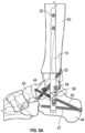
- An example of implant 10 finally inserted into calcaneus 46, talus 44, and tibia 40 and secured thereto with various bone screws is shown in Figs. 9A-C .
- a bone screw 54 can be inserted into talus 44 through slot 24 of implant 10.
- One or more screws 52 can then be inserted through openings 14, 16, 18, 20 of implant 10 and into tibia 40.
- a CoreLock TM device is either inserted into or is predisposed within implant 10, and can be translated using suitable instrumentation to cause translation of screw 54 from a first proximal position in slot 24 to second position that is distal of the first position.
- Such translation can be anywhere between about two millimeters to about ten millimeters (2-10mm), and in a specific example four millimeters (4mm), and can cause compression of the tibio-talar joint.
- a suitable CoreLock TM mechanism described in detail in the '031 Patent can be inserted or predisposed in implant 10 and used to cause translation of screw 54 in slot 24 using the corresponding instrumentation set forth in the '031 Patent
- a compression device 1024 (see e.g., Figs. ⁇ 45-45A) of the '031 Patent could be disposed within implant 10 and be aligned with slot 24.
- Second component 1076 of compression device 1024, in particular end opening 1084 thereof, can align with slot 24 so that screw 54 can be inserted through slot 24 and end opening 1084.
- suitable instrumentation from the '031 Patent can be inserted into implant 10 to engage and rotate threaded first component 1046 of compression device 1024 against threading 34 of bore 32 of implant 10.
- instrumentation can include a compression driver 1130 of the '031 Patent.
- compression driver 1130 might have a component that engages with jig nose 60 and/or a shaft that can be inserted through jig nose 60 and into implant 10 to engage and rotate first component 1046 of compression device 1024.
- Such rotation of first component 1046 as described previously, can cause compression device 1024 to move distally within slot 24 from its proximal position to a distal position and cause compression of the tibio-talar joint.
- Formations 1090 on compression device 1024 can, in the process, engage bone screw 54 and lock bone screw within slot 24 once bone screws 54 has reached its distal-most position or until maximum compression of the tibio-talar joint is achieved.
- bone screw 54 In its final position, in an example, bone screw 54 can extend medially about fifty degrees (50°) relative to sagittal plane 41.
- a bone screw 56 can then be inserted into calcaneus 46 through slot 28 of implant 10.
- compression instrument 90 can be used to internally compress and translate bone screw 56 from a first proximal position in slot 28 to a second position in slot 28 distal of the first position.
- such translation can be anywhere between about two millimeters to about ten millimeters (2-10mm), in a specific example four millimeters (4mm).
- first jig nose 60 can be attached to implant 10 by inserting protrusions 64 of jig nose 60 into recesses 39 of implant 10.
- jig nose 60 can be positively locked rotationally and longitudinally to implant 10 through any number of means, including threading, pressfitting, or other connection mechanisms.
- shaft 122 of compression post 120 of compression instrument 90 can be inserted into and through lumen 72 of jig nose 60 until anti-rotation frame 130 contacts jig nose 60.
- posts 144 of anti-rotation frame 130 can be inserted into recesses 78 in jig nose 60 and flange 142 can be arranged to rest on the surfaces of jig nose 60 surrounding its bore 72.
- Horseshoe 150 can then be applied to jig nose 60 and anti-rotation frame 130 to keep such components from separating as compression is applied in implant 10.
- both sets of arms 152, 154 can be slid around jig nose 60 and anti-rotation frame 130.
- first set of arms 152 can be positioned within cutouts or slots 133 in anti-rotation frame 130
- second set of arms 154 can be positioned within cutouts or slots 74 in jig nose 60.
- a recess (not shown) can be present on a wall of cutouts 133 in anti-rotation frame 130 to interact with deflectable tab 156 of arm 152.
- a wall of one of cutouts 133 can engage protrusion 158 of deflectable tab 156 and cause it to deflect inwardly in a direction away from axis 151. Then, when protrusion 158 reaches the aforementioned recess (not shown), deflectable tab 156 can resiliently deflect back in a direction towards axis 151 and become housed in the recess. A surgeon can therefore be provided with tactile and/or auditory feedback in the form of a click that horseshoe 150 has engaged fully.
- arms 152, 154 can prevent jig nose 60 and anti-rotation frame 150 from separating as arms 152, 154 contact cutouts 133, 74.
- a T-handle or other driving instrument (not shown) can then be attached to shaft 102 of compression nut 100 and rotated to cause rotation of compression nut 100.
- curved end 124 of compression post 120 can be arranged next to screw 56 within slot 28.
- second bore part 146 which can be polygon-shaped, can contact substantially-flat sections 128 of compression post 120 and retain compression post 120 in a rotationally locked position relative to anti-rotation frame 130.
- rotation of compression nut 100 can cause longitudinal translation of compression post 120 without corresponding rotation of compression post 120 due to ant-rotation frame 130.
- compression nut 100 can be retained longitudinally relative to anti-rotation frame 130 by virtue of pin(s) 135 riding in groove 110 of projection 108 of compression nut 100.
- Pin(s) 137 can also ride in slot 136 of anti-rotation frame 130 to determine the amount of movement of compression post 120.
- distance gauge markings 138 which can designate zero millimeters (0mm) of movement and four millimeters (4mm) of movement, can show the amount of movement of compression post 120 since such pin(s) 137 can ride in slot 136 as post 120 is moved distally.
- Compression nut 100 can be rotated to move compression post 120 distally and cause curved distal end 124 to contact screw 56 and move screw 56, internally within implant 10, from a first proximal position in slot 28 to a second position distal of the first position. Such movement of screw 56 can cause compression of the calcaneus-talar joint, as shown in Fig. 9A .
- the present implant 10 and compression instrument 90 can allow for two-stage internal compression within implant 10 to cause compression of the tibio-talar joint and the calcaneus-talar joint.
- Such internal compression can reduce problems commonly experienced with other compression techniques, such as bone float and misalignment. Internal compression can also avoid some issues that might be experienced with external compression, such as patient trauma.
- screw 56 In the final position, screw 56 can extend through calcaneus 46 roughly medial-to-lateral ( e.g ., substantially perpendicular to sagittal axis 41), as shown in Fig. 9C .
- Screw 55 can then be inserted into calcaneus 46, through angled opening 26 in implant 10, and into talus 44 across the subtalar joint (calcaneus-talar joint). Screws 55 can therefore fix the subtalar compression affected using the above method.
- Compression instrument 90 can then be removed from implant 10 as screw 55 maintains the subtalar compression.
- compression nut 100 can be rotated to cause compression post 120 to retract out of contact with screw 56 once screw 55 is inserted across the subtalar joint.
- horseshoe 150 can be removed and compression instrument 90 removed from connection with implant 10.
- screw 55 can extend twenty-five degrees (25°) superiorly relative to a transverse ankle plane and thirteen degrees (13°) medially relative to sagittal plane 41.
- screws 57 can be inserted into calcaneus 46 and through angled opening 30 in implant 10.
- screw 53 can extend into tibia 40, through angled opening 22, and into talus 44 across the tibio-talar joint.
- screw 53 can also extend into navicular 49 across the talar-navicular joint.
- screw 57 can extend five degrees (5°) superiorly relative to a transverse ankle plane and five degrees (5°) laterally relative to sagittal plane 41.
- screw 53 in its final position, screw 53 can extend forty-five degrees (45°) inferiorly relative to a transverse ankle plane and twenty-eight degrees (28°) medially relative to sagittal plane 41.
- the tibio-talar joint and the subtalar joint can be compressed internally in two-stages, and various screws can be used along with implant 10 to fix the compression and the ankle joint ( e.g ., for ankle fusion to occur).
- Suitable bone graft material or other augments can be used to assist with the fusion.
- any of openings 14, 16, 18, 20 can be threaded or unthreaded to engage with bone screws 52 and, likewise, any of angled openings 22, 26, 30 in any combination can be threaded or unthreaded to engage with the relevant bone screws.
- a CoreLock TM device can be used with angled openings 22, 26, 30 to lock an associated bone screw in any of openings 22, 26, 30. Such CoreLock TM devices are described in detail in the '031 and '590 Patents.
Landscapes
- Health & Medical Sciences (AREA)
- Orthopedic Medicine & Surgery (AREA)
- Surgery (AREA)
- Life Sciences & Earth Sciences (AREA)
- Heart & Thoracic Surgery (AREA)
- Nuclear Medicine, Radiotherapy & Molecular Imaging (AREA)
- Engineering & Computer Science (AREA)
- Biomedical Technology (AREA)
- Medical Informatics (AREA)
- Molecular Biology (AREA)
- Animal Behavior & Ethology (AREA)
- General Health & Medical Sciences (AREA)
- Public Health (AREA)
- Veterinary Medicine (AREA)
- Neurology (AREA)
- Prostheses (AREA)
- Surgical Instruments (AREA)
Claims (6)
- Implant pour arthrodèse de cheville (10) comprenant :une tige allongée (12) dimensionnée et façonnée de manière à être implantée dans un canal intramédullaire d'un tibia d'un patient, la tige allongée (12) comportant un alésage interne (32) ;ledit implant comprenant en outre :une première ouverture inclinée (22) à travers la tige (12), la première ouverture inclinée (22) définissant un premier axe qui s'étend à travers le tibia et dans un os astragale du patient sur toute l'étendue d'une articulation tibio-astragalienne lorsque l'implant est implanté ;une première fente allongée (24) à travers la tige (12), la première fente allongée (24) définissant un deuxième axe qui s'étend dans l'astragale du patient lorsque l'implant est implanté, la première fente allongée (24) étant conçue pour permettre la translation axiale d'un premier élément de fixation (54) par rapport à la tige (12) à l'intérieur de la première fente (24) d'une première position à une seconde position différente de manière à comprimer une articulation tibio-astragalienne ;une seconde fente allongée (28) à travers la tige (12), la seconde fente allongée définissant un troisième axe qui s'étend dans le calcanéum du patient lorsque l'implant est implanté, la seconde fente allongée (28) étant conçue pour permettre la translation axiale d'un deuxième élément de fixation (56) par rapport à la tige (12) à l'intérieur de la seconde fente (28) d'une première position à une seconde position différente de manière à comprimer une articulation sous-astragalienne ; etune deuxième ouverture inclinée (26) à travers la tige (12), la deuxième ouverture inclinée définissant un troisième axe qui s'étend dans un os calcanéum du patient lorsque l'implant est implanté.
- Implant selon la revendication 1, ledit alésage interne (32) étant fileté.
- Système d'implant comprenant l'implant selon l'une quelconque des revendications 1 à 2 et des premier, deuxième, troisième et quatrième éléments de fixation définissant chacun un diamètre, lesdites première et seconde fentes allongées (24, 28) présentant chacune une longueur qui se trouve n'importe où entre environ 125 à 500 % du diamètre des deuxième et troisième éléments de fixation (54, 56), et une largeur qui est sensiblement inférieure ou égale à 120 % du diamètre des deuxième et troisième éléments de fixation (54, 56), respectivement.
- Système d'implant selon la revendication 3, comprenant en outre une pince télescopique qui possède un corps définissant une première zone façonnée de manière à venir en prise avec le premier élément de fixation, ladite pince télescopique pouvant être disposée dans l'alésage interne (32) de l'implant adjacent à la première fente (24) et étant mobile à l'intérieur de l'alésage interne (32), le premier élément de fixation se trouvant dans la première fente (24), de sorte que la première zone du corps de la pince télescopique vienne en prise avec la tige du premier élément de fixation et déplace le premier élément de fixation d'une première position dans la première fente (24) à une seconde position différente.
- Implant ou système d'implant selon l'une quelconque des revendications 2 à 4, comprenant en outre une troisième ouverture inclinée (30) à travers la tige (12), la troisième ouverture angulaire (30) définissant un quatrième axe qui s'étend à travers le calcanéum et dans un os astragale du patient sur toute l'étendue de l'articulation sous-astragalienne lorsque l'implant est implanté.
- Implant ou système d'implant selon l'une quelconque des revendications 1 à 5, ledit implant (10) étant un clou intramédullaire.
Applications Claiming Priority (2)
| Application Number | Priority Date | Filing Date | Title |
|---|---|---|---|
| US201662439545P | 2016-12-28 | 2016-12-28 | |
| PCT/US2017/068091 WO2018125779A1 (fr) | 2016-12-28 | 2017-12-22 | Instrumentation de compression d'articulation |
Publications (2)
| Publication Number | Publication Date |
|---|---|
| EP3562417A1 EP3562417A1 (fr) | 2019-11-06 |
| EP3562417B1 true EP3562417B1 (fr) | 2023-07-12 |
Family
ID=61157284
Family Applications (1)
| Application Number | Title | Priority Date | Filing Date |
|---|---|---|---|
| EP17838106.7A Active EP3562417B1 (fr) | 2016-12-28 | 2017-12-22 | Instrumentation de compression d'articulation |
Country Status (4)
| Country | Link |
|---|---|
| US (1) | US10869701B2 (fr) |
| EP (1) | EP3562417B1 (fr) |
| CN (1) | CN110352041B (fr) |
| WO (1) | WO2018125779A1 (fr) |
Families Citing this family (10)
| Publication number | Priority date | Publication date | Assignee | Title |
|---|---|---|---|---|
| US20220151664A1 (en) * | 2015-04-16 | 2022-05-19 | Texas Tech University System | Ankle (Tibio-Talar) Fusion Nail |
| EP3562417B1 (fr) | 2016-12-28 | 2023-07-12 | Biomet Manufacturing, LLC | Instrumentation de compression d'articulation |
| US11547456B2 (en) * | 2017-01-12 | 2023-01-10 | Dt Medtech, Llc | Internal ankle fixation systems, foot securement and jig devices, and related methods |
| US10932828B2 (en) | 2018-01-25 | 2021-03-02 | Advanced Orthopaedic Solutions, Inc. | Bone nail |
| CN109171920A (zh) * | 2018-10-08 | 2019-01-11 | 大泗医疗生物科技有限公司 | 足踝融合结构及关节融合装置 |
| IT201900005180A1 (it) * | 2019-04-05 | 2020-10-05 | Enrico Paganelli | Chiodo endomidollare |
| ES2966519T3 (es) | 2020-03-18 | 2024-04-22 | Orthofix Srl | Dispositivo de artrodesis mejorado |
| TR202017292A1 (tr) * | 2020-10-30 | 2022-05-23 | Tst Rakor Ve Tibbi Aletler Sanayi Ve Ticaret Ltd Sirketi | Artrodez çi̇vi̇si̇ |
| WO2025085296A1 (fr) | 2023-10-18 | 2025-04-24 | Zimmer, Inc. | Procédés, systèmes et appareils pour la coupe d'os |
| WO2026075913A1 (fr) | 2024-10-02 | 2026-04-09 | Zimmer, Inc. | Groupe de vis distales pour clou tibial intramédullaire |
Citations (3)
| Publication number | Priority date | Publication date | Assignee | Title |
|---|---|---|---|---|
| US20080183171A1 (en) * | 2007-01-26 | 2008-07-31 | Ebi, L.P. | Lockable intermedullary fixation device |
| US20120197255A1 (en) * | 2007-01-26 | 2012-08-02 | Biomet Manufacturing Corp. | Lockable Intramedullary Fixation Device |
| US20120330313A1 (en) * | 2010-12-03 | 2012-12-27 | Grady John F | Intramedullary nail technology |
Family Cites Families (9)
| Publication number | Priority date | Publication date | Assignee | Title |
|---|---|---|---|---|
| US7485119B2 (en) * | 2000-03-07 | 2009-02-03 | Zimmer Technology, Inc. | Method and apparatus for reducing femoral fractures |
| DE20012877U1 (de) * | 2000-07-26 | 2001-12-06 | stryker Trauma GmbH, 24232 Schönkirchen | Verriegelungsnagel |
| US8157802B2 (en) * | 2007-01-26 | 2012-04-17 | Ebi, Llc | Intramedullary implant with locking and compression devices |
| CA2767005A1 (fr) * | 2009-07-01 | 2011-01-06 | Synthes Usa, Llc | Clou intramedullaire et mecanisme de blocage de vis en saillie |
| ES2551874T3 (es) * | 2011-02-08 | 2015-11-24 | Stryker Trauma Gmbh | Sistema de implante para fijación ósea |
| BR112013020956B1 (pt) | 2011-02-14 | 2020-12-08 | Synthes Gmbh | conjunto de fixação óssea |
| WO2013134387A1 (fr) * | 2012-03-08 | 2013-09-12 | Biomet Manufacturing Corp. | Dispositif blocable de fixation intra-médullaire |
| US20140188179A1 (en) * | 2012-12-27 | 2014-07-03 | Wright Medical Technology, Inc. | Percutaneous flaring hammertoe fixation implant and instrument |
| EP3562417B1 (fr) | 2016-12-28 | 2023-07-12 | Biomet Manufacturing, LLC | Instrumentation de compression d'articulation |
-
2017
- 2017-12-22 EP EP17838106.7A patent/EP3562417B1/fr active Active
- 2017-12-22 WO PCT/US2017/068091 patent/WO2018125779A1/fr not_active Ceased
- 2017-12-22 US US15/851,943 patent/US10869701B2/en active Active
- 2017-12-22 CN CN201780081013.8A patent/CN110352041B/zh active Active
Patent Citations (3)
| Publication number | Priority date | Publication date | Assignee | Title |
|---|---|---|---|---|
| US20080183171A1 (en) * | 2007-01-26 | 2008-07-31 | Ebi, L.P. | Lockable intermedullary fixation device |
| US20120197255A1 (en) * | 2007-01-26 | 2012-08-02 | Biomet Manufacturing Corp. | Lockable Intramedullary Fixation Device |
| US20120330313A1 (en) * | 2010-12-03 | 2012-12-27 | Grady John F | Intramedullary nail technology |
Also Published As
| Publication number | Publication date |
|---|---|
| EP3562417A1 (fr) | 2019-11-06 |
| US10869701B2 (en) | 2020-12-22 |
| CN110352041B (zh) | 2022-12-02 |
| US20180177537A1 (en) | 2018-06-28 |
| CN110352041A (zh) | 2019-10-18 |
| WO2018125779A1 (fr) | 2018-07-05 |
Similar Documents
| Publication | Publication Date | Title |
|---|---|---|
| EP3562417B1 (fr) | Instrumentation de compression d'articulation | |
| US10357299B2 (en) | Bone joining apparatus and method | |
| EP3624707B1 (fr) | Dispositifs d'alésage d'articulation | |
| AU2017272257B2 (en) | Interphalangeal joint implant methods and apparatus | |
| EP2670360B1 (fr) | Plaque d'arthroplastie | |
| US9295556B2 (en) | Minimally invasive total hip replacement | |
| US20110172781A1 (en) | Elbow prosthesis | |
| US12370054B2 (en) | Implants, systems, and methods of use and assembly | |
| AU2020307535B2 (en) | Distal radioulnar joint prosthesis system and method of use | |
| US12396757B2 (en) | Implants and methods for treating Charcot foot and other conditions | |
| EP3592265B1 (fr) | Dispositifs d'implant osseux | |
| EP4732795A2 (fr) | Trajectoires de vis dans un clou d'arthrodèse de cheville | |
| US20240130764A1 (en) | Bone fracture fixation device and related systems and methods |
Legal Events
| Date | Code | Title | Description |
|---|---|---|---|
| STAA | Information on the status of an ep patent application or granted ep patent |
Free format text: STATUS: UNKNOWN |
|
| STAA | Information on the status of an ep patent application or granted ep patent |
Free format text: STATUS: THE INTERNATIONAL PUBLICATION HAS BEEN MADE |
|
| PUAI | Public reference made under article 153(3) epc to a published international application that has entered the european phase |
Free format text: ORIGINAL CODE: 0009012 |
|
| STAA | Information on the status of an ep patent application or granted ep patent |
Free format text: STATUS: REQUEST FOR EXAMINATION WAS MADE |
|
| 17P | Request for examination filed |
Effective date: 20190722 |
|
| AK | Designated contracting states |
Kind code of ref document: A1 Designated state(s): AL AT BE BG CH CY CZ DE DK EE ES FI FR GB GR HR HU IE IS IT LI LT LU LV MC MK MT NL NO PL PT RO RS SE SI SK SM TR |
|
| AX | Request for extension of the european patent |
Extension state: BA ME |
|
| DAV | Request for validation of the european patent (deleted) | ||
| DAX | Request for extension of the european patent (deleted) | ||
| PUAG | Search results despatched under rule 164(2) epc together with communication from examining division |
Free format text: ORIGINAL CODE: 0009017 |
|
| STAA | Information on the status of an ep patent application or granted ep patent |
Free format text: STATUS: EXAMINATION IS IN PROGRESS |
|
| 17Q | First examination report despatched |
Effective date: 20210419 |
|
| B565 | Issuance of search results under rule 164(2) epc |
Effective date: 20210419 |
|
| RIC1 | Information provided on ipc code assigned before grant |
Ipc: A61B 17/72 20060101AFI20210414BHEP Ipc: A61B 17/88 20060101ALI20210414BHEP |
|
| GRAP | Despatch of communication of intention to grant a patent |
Free format text: ORIGINAL CODE: EPIDOSNIGR1 |
|
| STAA | Information on the status of an ep patent application or granted ep patent |
Free format text: STATUS: GRANT OF PATENT IS INTENDED |
|
| INTG | Intention to grant announced |
Effective date: 20230123 |
|
| GRAS | Grant fee paid |
Free format text: ORIGINAL CODE: EPIDOSNIGR3 |
|
| GRAA | (expected) grant |
Free format text: ORIGINAL CODE: 0009210 |
|
| STAA | Information on the status of an ep patent application or granted ep patent |
Free format text: STATUS: THE PATENT HAS BEEN GRANTED |
|
| AK | Designated contracting states |
Kind code of ref document: B1 Designated state(s): AL AT BE BG CH CY CZ DE DK EE ES FI FR GB GR HR HU IE IS IT LI LT LU LV MC MK MT NL NO PL PT RO RS SE SI SK SM TR |
|
| REG | Reference to a national code |
Ref country code: CH Ref legal event code: EP |
|
| REG | Reference to a national code |
Ref country code: IE Ref legal event code: FG4D |
|
| REG | Reference to a national code |
Ref country code: DE Ref legal event code: R096 Ref document number: 602017071288 Country of ref document: DE |
|
| REG | Reference to a national code |
Ref country code: LT Ref legal event code: MG9D |
|
| REG | Reference to a national code |
Ref country code: NL Ref legal event code: MP Effective date: 20230712 |
|
| REG | Reference to a national code |
Ref country code: AT Ref legal event code: MK05 Ref document number: 1586254 Country of ref document: AT Kind code of ref document: T Effective date: 20230712 |
|
| PG25 | Lapsed in a contracting state [announced via postgrant information from national office to epo] |
Ref country code: NL Free format text: LAPSE BECAUSE OF FAILURE TO SUBMIT A TRANSLATION OF THE DESCRIPTION OR TO PAY THE FEE WITHIN THE PRESCRIBED TIME-LIMIT Effective date: 20230712 |
|
| PG25 | Lapsed in a contracting state [announced via postgrant information from national office to epo] |
Ref country code: GR Free format text: LAPSE BECAUSE OF FAILURE TO SUBMIT A TRANSLATION OF THE DESCRIPTION OR TO PAY THE FEE WITHIN THE PRESCRIBED TIME-LIMIT Effective date: 20231013 |
|
| PG25 | Lapsed in a contracting state [announced via postgrant information from national office to epo] |
Ref country code: ES Free format text: LAPSE BECAUSE OF FAILURE TO SUBMIT A TRANSLATION OF THE DESCRIPTION OR TO PAY THE FEE WITHIN THE PRESCRIBED TIME-LIMIT Effective date: 20230712 |
|
| PG25 | Lapsed in a contracting state [announced via postgrant information from national office to epo] |
Ref country code: IS Free format text: LAPSE BECAUSE OF FAILURE TO SUBMIT A TRANSLATION OF THE DESCRIPTION OR TO PAY THE FEE WITHIN THE PRESCRIBED TIME-LIMIT Effective date: 20231112 |
|
| PG25 | Lapsed in a contracting state [announced via postgrant information from national office to epo] |
Ref country code: SE Free format text: LAPSE BECAUSE OF FAILURE TO SUBMIT A TRANSLATION OF THE DESCRIPTION OR TO PAY THE FEE WITHIN THE PRESCRIBED TIME-LIMIT Effective date: 20230712 Ref country code: RS Free format text: LAPSE BECAUSE OF FAILURE TO SUBMIT A TRANSLATION OF THE DESCRIPTION OR TO PAY THE FEE WITHIN THE PRESCRIBED TIME-LIMIT Effective date: 20230712 Ref country code: PT Free format text: LAPSE BECAUSE OF FAILURE TO SUBMIT A TRANSLATION OF THE DESCRIPTION OR TO PAY THE FEE WITHIN THE PRESCRIBED TIME-LIMIT Effective date: 20231113 Ref country code: NO Free format text: LAPSE BECAUSE OF FAILURE TO SUBMIT A TRANSLATION OF THE DESCRIPTION OR TO PAY THE FEE WITHIN THE PRESCRIBED TIME-LIMIT Effective date: 20231012 Ref country code: LV Free format text: LAPSE BECAUSE OF FAILURE TO SUBMIT A TRANSLATION OF THE DESCRIPTION OR TO PAY THE FEE WITHIN THE PRESCRIBED TIME-LIMIT Effective date: 20230712 Ref country code: LT Free format text: LAPSE BECAUSE OF FAILURE TO SUBMIT A TRANSLATION OF THE DESCRIPTION OR TO PAY THE FEE WITHIN THE PRESCRIBED TIME-LIMIT Effective date: 20230712 Ref country code: IS Free format text: LAPSE BECAUSE OF FAILURE TO SUBMIT A TRANSLATION OF THE DESCRIPTION OR TO PAY THE FEE WITHIN THE PRESCRIBED TIME-LIMIT Effective date: 20231112 Ref country code: HR Free format text: LAPSE BECAUSE OF FAILURE TO SUBMIT A TRANSLATION OF THE DESCRIPTION OR TO PAY THE FEE WITHIN THE PRESCRIBED TIME-LIMIT Effective date: 20230712 Ref country code: GR Free format text: LAPSE BECAUSE OF FAILURE TO SUBMIT A TRANSLATION OF THE DESCRIPTION OR TO PAY THE FEE WITHIN THE PRESCRIBED TIME-LIMIT Effective date: 20231013 Ref country code: FI Free format text: LAPSE BECAUSE OF FAILURE TO SUBMIT A TRANSLATION OF THE DESCRIPTION OR TO PAY THE FEE WITHIN THE PRESCRIBED TIME-LIMIT Effective date: 20230712 Ref country code: ES Free format text: LAPSE BECAUSE OF FAILURE TO SUBMIT A TRANSLATION OF THE DESCRIPTION OR TO PAY THE FEE WITHIN THE PRESCRIBED TIME-LIMIT Effective date: 20230712 Ref country code: AT Free format text: LAPSE BECAUSE OF FAILURE TO SUBMIT A TRANSLATION OF THE DESCRIPTION OR TO PAY THE FEE WITHIN THE PRESCRIBED TIME-LIMIT Effective date: 20230712 |
|
| PG25 | Lapsed in a contracting state [announced via postgrant information from national office to epo] |
Ref country code: PL Free format text: LAPSE BECAUSE OF FAILURE TO SUBMIT A TRANSLATION OF THE DESCRIPTION OR TO PAY THE FEE WITHIN THE PRESCRIBED TIME-LIMIT Effective date: 20230712 |
|
| REG | Reference to a national code |
Ref country code: DE Ref legal event code: R097 Ref document number: 602017071288 Country of ref document: DE |
|
| PG25 | Lapsed in a contracting state [announced via postgrant information from national office to epo] |
Ref country code: SM Free format text: LAPSE BECAUSE OF FAILURE TO SUBMIT A TRANSLATION OF THE DESCRIPTION OR TO PAY THE FEE WITHIN THE PRESCRIBED TIME-LIMIT Effective date: 20230712 Ref country code: RO Free format text: LAPSE BECAUSE OF FAILURE TO SUBMIT A TRANSLATION OF THE DESCRIPTION OR TO PAY THE FEE WITHIN THE PRESCRIBED TIME-LIMIT Effective date: 20230712 Ref country code: EE Free format text: LAPSE BECAUSE OF FAILURE TO SUBMIT A TRANSLATION OF THE DESCRIPTION OR TO PAY THE FEE WITHIN THE PRESCRIBED TIME-LIMIT Effective date: 20230712 Ref country code: DK Free format text: LAPSE BECAUSE OF FAILURE TO SUBMIT A TRANSLATION OF THE DESCRIPTION OR TO PAY THE FEE WITHIN THE PRESCRIBED TIME-LIMIT Effective date: 20230712 Ref country code: CZ Free format text: LAPSE BECAUSE OF FAILURE TO SUBMIT A TRANSLATION OF THE DESCRIPTION OR TO PAY THE FEE WITHIN THE PRESCRIBED TIME-LIMIT Effective date: 20230712 Ref country code: SK Free format text: LAPSE BECAUSE OF FAILURE TO SUBMIT A TRANSLATION OF THE DESCRIPTION OR TO PAY THE FEE WITHIN THE PRESCRIBED TIME-LIMIT Effective date: 20230712 |
|
| P01 | Opt-out of the competence of the unified patent court (upc) registered |
Effective date: 20240326 |
|
| PLBE | No opposition filed within time limit |
Free format text: ORIGINAL CODE: 0009261 |
|
| STAA | Information on the status of an ep patent application or granted ep patent |
Free format text: STATUS: NO OPPOSITION FILED WITHIN TIME LIMIT |
|
| PG25 | Lapsed in a contracting state [announced via postgrant information from national office to epo] |
Ref country code: IT Free format text: LAPSE BECAUSE OF FAILURE TO SUBMIT A TRANSLATION OF THE DESCRIPTION OR TO PAY THE FEE WITHIN THE PRESCRIBED TIME-LIMIT Effective date: 20230712 |
|
| 26N | No opposition filed |
Effective date: 20240415 |
|
| PG25 | Lapsed in a contracting state [announced via postgrant information from national office to epo] |
Ref country code: SI Free format text: LAPSE BECAUSE OF FAILURE TO SUBMIT A TRANSLATION OF THE DESCRIPTION OR TO PAY THE FEE WITHIN THE PRESCRIBED TIME-LIMIT Effective date: 20230712 |
|
| PG25 | Lapsed in a contracting state [announced via postgrant information from national office to epo] |
Ref country code: LU Free format text: LAPSE BECAUSE OF NON-PAYMENT OF DUE FEES Effective date: 20231222 |
|
| PG25 | Lapsed in a contracting state [announced via postgrant information from national office to epo] |
Ref country code: MC Free format text: LAPSE BECAUSE OF FAILURE TO SUBMIT A TRANSLATION OF THE DESCRIPTION OR TO PAY THE FEE WITHIN THE PRESCRIBED TIME-LIMIT Effective date: 20230712 |
|
| REG | Reference to a national code |
Ref country code: BE Ref legal event code: MM Effective date: 20231231 |
|
| PG25 | Lapsed in a contracting state [announced via postgrant information from national office to epo] |
Ref country code: MC Free format text: LAPSE BECAUSE OF FAILURE TO SUBMIT A TRANSLATION OF THE DESCRIPTION OR TO PAY THE FEE WITHIN THE PRESCRIBED TIME-LIMIT Effective date: 20230712 Ref country code: LU Free format text: LAPSE BECAUSE OF NON-PAYMENT OF DUE FEES Effective date: 20231222 |
|
| REG | Reference to a national code |
Ref country code: IE Ref legal event code: MM4A |
|
| PG25 | Lapsed in a contracting state [announced via postgrant information from national office to epo] |
Ref country code: IE Free format text: LAPSE BECAUSE OF NON-PAYMENT OF DUE FEES Effective date: 20231222 |
|
| PG25 | Lapsed in a contracting state [announced via postgrant information from national office to epo] |
Ref country code: BE Free format text: LAPSE BECAUSE OF NON-PAYMENT OF DUE FEES Effective date: 20231231 |
|
| PG25 | Lapsed in a contracting state [announced via postgrant information from national office to epo] |
Ref country code: FR Free format text: LAPSE BECAUSE OF NON-PAYMENT OF DUE FEES Effective date: 20231231 |
|
| PG25 | Lapsed in a contracting state [announced via postgrant information from national office to epo] |
Ref country code: IE Free format text: LAPSE BECAUSE OF NON-PAYMENT OF DUE FEES Effective date: 20231222 Ref country code: FR Free format text: LAPSE BECAUSE OF NON-PAYMENT OF DUE FEES Effective date: 20231231 Ref country code: BE Free format text: LAPSE BECAUSE OF NON-PAYMENT OF DUE FEES Effective date: 20231231 |
|
| PG25 | Lapsed in a contracting state [announced via postgrant information from national office to epo] |
Ref country code: BG Free format text: LAPSE BECAUSE OF FAILURE TO SUBMIT A TRANSLATION OF THE DESCRIPTION OR TO PAY THE FEE WITHIN THE PRESCRIBED TIME-LIMIT Effective date: 20230712 |
|
| PG25 | Lapsed in a contracting state [announced via postgrant information from national office to epo] |
Ref country code: BG Free format text: LAPSE BECAUSE OF FAILURE TO SUBMIT A TRANSLATION OF THE DESCRIPTION OR TO PAY THE FEE WITHIN THE PRESCRIBED TIME-LIMIT Effective date: 20230712 |
|
| PGFP | Annual fee paid to national office [announced via postgrant information from national office to epo] |
Ref country code: CH Payment date: 20250101 Year of fee payment: 8 |
|
| PG25 | Lapsed in a contracting state [announced via postgrant information from national office to epo] |
Ref country code: CY Free format text: LAPSE BECAUSE OF FAILURE TO SUBMIT A TRANSLATION OF THE DESCRIPTION OR TO PAY THE FEE WITHIN THE PRESCRIBED TIME-LIMIT; INVALID AB INITIO Effective date: 20171222 |
|
| PG25 | Lapsed in a contracting state [announced via postgrant information from national office to epo] |
Ref country code: HU Free format text: LAPSE BECAUSE OF FAILURE TO SUBMIT A TRANSLATION OF THE DESCRIPTION OR TO PAY THE FEE WITHIN THE PRESCRIBED TIME-LIMIT; INVALID AB INITIO Effective date: 20171222 |
|
| PG25 | Lapsed in a contracting state [announced via postgrant information from national office to epo] |
Ref country code: TR Free format text: LAPSE BECAUSE OF FAILURE TO SUBMIT A TRANSLATION OF THE DESCRIPTION OR TO PAY THE FEE WITHIN THE PRESCRIBED TIME-LIMIT Effective date: 20230712 |
|
| REG | Reference to a national code |
Ref country code: CH Ref legal event code: U11 Free format text: ST27 STATUS EVENT CODE: U-0-0-U10-U11 (AS PROVIDED BY THE NATIONAL OFFICE) Effective date: 20260101 |
|
| PGFP | Annual fee paid to national office [announced via postgrant information from national office to epo] |
Ref country code: DE Payment date: 20251112 Year of fee payment: 9 |
|
| PGFP | Annual fee paid to national office [announced via postgrant information from national office to epo] |
Ref country code: GB Payment date: 20251114 Year of fee payment: 9 |