EP3565724B1 - Support à base de matière plastique pour panneau de mur ou de plancher décoré - Google Patents
Support à base de matière plastique pour panneau de mur ou de plancher décoré Download PDFInfo
- Publication number
- EP3565724B1 EP3565724B1 EP17826257.2A EP17826257A EP3565724B1 EP 3565724 B1 EP3565724 B1 EP 3565724B1 EP 17826257 A EP17826257 A EP 17826257A EP 3565724 B1 EP3565724 B1 EP 3565724B1
- Authority
- EP
- European Patent Office
- Prior art keywords
- carrier
- density
- thickness
- layer
- along
- Prior art date
- Legal status (The legal status is an assumption and is not a legal conclusion. Google has not performed a legal analysis and makes no representation as to the accuracy of the status listed.)
- Active
Links
Images


Classifications
-
- B—PERFORMING OPERATIONS; TRANSPORTING
- B44—DECORATIVE ARTS
- B44C—PRODUCING DECORATIVE EFFECTS; MOSAICS; TARSIA WORK; PAPERHANGING
- B44C5/00—Processes for producing special ornamental bodies
- B44C5/04—Ornamental plaques, e.g. decorative panels, decorative veneers
-
- B—PERFORMING OPERATIONS; TRANSPORTING
- B32—LAYERED PRODUCTS
- B32B—LAYERED PRODUCTS, i.e. PRODUCTS BUILT-UP OF STRATA OF FLAT OR NON-FLAT, e.g. CELLULAR OR HONEYCOMB, FORM
- B32B19/00—Layered products comprising a layer of natural mineral fibres or particles, e.g. asbestos, mica
- B32B19/02—Layered products comprising a layer of natural mineral fibres or particles, e.g. asbestos, mica the layer of fibres or particles being impregnated or embedded in a plastic substance
-
- B—PERFORMING OPERATIONS; TRANSPORTING
- B32—LAYERED PRODUCTS
- B32B—LAYERED PRODUCTS, i.e. PRODUCTS BUILT-UP OF STRATA OF FLAT OR NON-FLAT, e.g. CELLULAR OR HONEYCOMB, FORM
- B32B23/00—Layered products comprising a layer of cellulosic plastic substances, i.e. substances obtained by chemical modification of cellulose, e.g. cellulose ethers, cellulose esters, viscose
- B32B23/04—Layered products comprising a layer of cellulosic plastic substances, i.e. substances obtained by chemical modification of cellulose, e.g. cellulose ethers, cellulose esters, viscose comprising such cellulosic plastic substance as the main or only constituent of a layer, which is next to another layer of the same or of a different material
-
- B—PERFORMING OPERATIONS; TRANSPORTING
- B32—LAYERED PRODUCTS
- B32B—LAYERED PRODUCTS, i.e. PRODUCTS BUILT-UP OF STRATA OF FLAT OR NON-FLAT, e.g. CELLULAR OR HONEYCOMB, FORM
- B32B29/00—Layered products comprising a layer of paper or cardboard
- B32B29/04—Layered products comprising a layer of paper or cardboard next to a particulate layer
-
- B—PERFORMING OPERATIONS; TRANSPORTING
- B32—LAYERED PRODUCTS
- B32B—LAYERED PRODUCTS, i.e. PRODUCTS BUILT-UP OF STRATA OF FLAT OR NON-FLAT, e.g. CELLULAR OR HONEYCOMB, FORM
- B32B5/00—Layered products characterised by the non- homogeneity or physical structure, i.e. comprising a fibrous, filamentary, particulate or foam layer; Layered products characterised by having a layer differing constitutionally or physically in different parts
- B32B5/14—Layered products characterised by the non- homogeneity or physical structure, i.e. comprising a fibrous, filamentary, particulate or foam layer; Layered products characterised by having a layer differing constitutionally or physically in different parts characterised by a layer differing constitutionally or physically in different parts, e.g. denser near its faces
- B32B5/145—Variation across the thickness of the layer
-
- B—PERFORMING OPERATIONS; TRANSPORTING
- B32—LAYERED PRODUCTS
- B32B—LAYERED PRODUCTS, i.e. PRODUCTS BUILT-UP OF STRATA OF FLAT OR NON-FLAT, e.g. CELLULAR OR HONEYCOMB, FORM
- B32B5/00—Layered products characterised by the non- homogeneity or physical structure, i.e. comprising a fibrous, filamentary, particulate or foam layer; Layered products characterised by having a layer differing constitutionally or physically in different parts
- B32B5/16—Layered products characterised by the non- homogeneity or physical structure, i.e. comprising a fibrous, filamentary, particulate or foam layer; Layered products characterised by having a layer differing constitutionally or physically in different parts characterised by features of a layer formed of particles, e.g. chips, powder or granules
-
- B—PERFORMING OPERATIONS; TRANSPORTING
- B32—LAYERED PRODUCTS
- B32B—LAYERED PRODUCTS, i.e. PRODUCTS BUILT-UP OF STRATA OF FLAT OR NON-FLAT, e.g. CELLULAR OR HONEYCOMB, FORM
- B32B5/00—Layered products characterised by the non- homogeneity or physical structure, i.e. comprising a fibrous, filamentary, particulate or foam layer; Layered products characterised by having a layer differing constitutionally or physically in different parts
- B32B5/22—Layered products characterised by the non- homogeneity or physical structure, i.e. comprising a fibrous, filamentary, particulate or foam layer; Layered products characterised by having a layer differing constitutionally or physically in different parts characterised by the presence of two or more layers which are next to each other and are fibrous, filamentary, formed of particles or foamed
- B32B5/30—Layered products characterised by the non- homogeneity or physical structure, i.e. comprising a fibrous, filamentary, particulate or foam layer; Layered products characterised by having a layer differing constitutionally or physically in different parts characterised by the presence of two or more layers which are next to each other and are fibrous, filamentary, formed of particles or foamed one layer being formed of particles, e.g. chips, granules, powder
-
- B—PERFORMING OPERATIONS; TRANSPORTING
- B32—LAYERED PRODUCTS
- B32B—LAYERED PRODUCTS, i.e. PRODUCTS BUILT-UP OF STRATA OF FLAT OR NON-FLAT, e.g. CELLULAR OR HONEYCOMB, FORM
- B32B7/00—Layered products characterised by the relation between layers; Layered products characterised by the relative orientation of features between layers, or by the relative values of a measurable parameter between layers, i.e. products comprising layers having different physical, chemical or physicochemical properties; Layered products characterised by the interconnection of layers
- B32B7/02—Physical, chemical or physicochemical properties
- B32B7/022—Mechanical properties
-
- B—PERFORMING OPERATIONS; TRANSPORTING
- B32—LAYERED PRODUCTS
- B32B—LAYERED PRODUCTS, i.e. PRODUCTS BUILT-UP OF STRATA OF FLAT OR NON-FLAT, e.g. CELLULAR OR HONEYCOMB, FORM
- B32B2260/00—Layered product comprising an impregnated, embedded, or bonded layer wherein the layer comprises an impregnation, embedding, or binder material
- B32B2260/02—Composition of the impregnated, bonded or embedded layer
- B32B2260/021—Fibrous or filamentary layer
-
- B—PERFORMING OPERATIONS; TRANSPORTING
- B32—LAYERED PRODUCTS
- B32B—LAYERED PRODUCTS, i.e. PRODUCTS BUILT-UP OF STRATA OF FLAT OR NON-FLAT, e.g. CELLULAR OR HONEYCOMB, FORM
- B32B2260/00—Layered product comprising an impregnated, embedded, or bonded layer wherein the layer comprises an impregnation, embedding, or binder material
- B32B2260/02—Composition of the impregnated, bonded or embedded layer
- B32B2260/025—Particulate layer
-
- B—PERFORMING OPERATIONS; TRANSPORTING
- B32—LAYERED PRODUCTS
- B32B—LAYERED PRODUCTS, i.e. PRODUCTS BUILT-UP OF STRATA OF FLAT OR NON-FLAT, e.g. CELLULAR OR HONEYCOMB, FORM
- B32B2260/00—Layered product comprising an impregnated, embedded, or bonded layer wherein the layer comprises an impregnation, embedding, or binder material
- B32B2260/02—Composition of the impregnated, bonded or embedded layer
- B32B2260/028—Paper layer
-
- B—PERFORMING OPERATIONS; TRANSPORTING
- B32—LAYERED PRODUCTS
- B32B—LAYERED PRODUCTS, i.e. PRODUCTS BUILT-UP OF STRATA OF FLAT OR NON-FLAT, e.g. CELLULAR OR HONEYCOMB, FORM
- B32B2260/00—Layered product comprising an impregnated, embedded, or bonded layer wherein the layer comprises an impregnation, embedding, or binder material
- B32B2260/04—Impregnation, embedding, or binder material
- B32B2260/046—Synthetic resin
-
- B—PERFORMING OPERATIONS; TRANSPORTING
- B32—LAYERED PRODUCTS
- B32B—LAYERED PRODUCTS, i.e. PRODUCTS BUILT-UP OF STRATA OF FLAT OR NON-FLAT, e.g. CELLULAR OR HONEYCOMB, FORM
- B32B2262/00—Composition or structural features of fibres which form a fibrous or filamentary layer or are present as additives
- B32B2262/06—Vegetal fibres
-
- B—PERFORMING OPERATIONS; TRANSPORTING
- B32—LAYERED PRODUCTS
- B32B—LAYERED PRODUCTS, i.e. PRODUCTS BUILT-UP OF STRATA OF FLAT OR NON-FLAT, e.g. CELLULAR OR HONEYCOMB, FORM
- B32B2262/00—Composition or structural features of fibres which form a fibrous or filamentary layer or are present as additives
- B32B2262/08—Animal fibres, e.g. hair, wool, silk
-
- B—PERFORMING OPERATIONS; TRANSPORTING
- B32—LAYERED PRODUCTS
- B32B—LAYERED PRODUCTS, i.e. PRODUCTS BUILT-UP OF STRATA OF FLAT OR NON-FLAT, e.g. CELLULAR OR HONEYCOMB, FORM
- B32B2264/00—Composition or properties of particles which form a particulate layer or are present as additives
- B32B2264/06—Vegetal particles
- B32B2264/062—Cellulose particles, e.g. cotton
- B32B2264/067—Wood particles
-
- B—PERFORMING OPERATIONS; TRANSPORTING
- B32—LAYERED PRODUCTS
- B32B—LAYERED PRODUCTS, i.e. PRODUCTS BUILT-UP OF STRATA OF FLAT OR NON-FLAT, e.g. CELLULAR OR HONEYCOMB, FORM
- B32B2264/00—Composition or properties of particles which form a particulate layer or are present as additives
- B32B2264/10—Inorganic particles
-
- B—PERFORMING OPERATIONS; TRANSPORTING
- B32—LAYERED PRODUCTS
- B32B—LAYERED PRODUCTS, i.e. PRODUCTS BUILT-UP OF STRATA OF FLAT OR NON-FLAT, e.g. CELLULAR OR HONEYCOMB, FORM
- B32B2307/00—Properties of the layers or laminate
- B32B2307/40—Properties of the layers or laminate having particular optical properties
- B32B2307/402—Coloured
- B32B2307/4026—Coloured within the layer by addition of a colorant, e.g. pigments, dyes
-
- B—PERFORMING OPERATIONS; TRANSPORTING
- B32—LAYERED PRODUCTS
- B32B—LAYERED PRODUCTS, i.e. PRODUCTS BUILT-UP OF STRATA OF FLAT OR NON-FLAT, e.g. CELLULAR OR HONEYCOMB, FORM
- B32B2307/00—Properties of the layers or laminate
- B32B2307/70—Other properties
- B32B2307/72—Density
-
- B—PERFORMING OPERATIONS; TRANSPORTING
- B32—LAYERED PRODUCTS
- B32B—LAYERED PRODUCTS, i.e. PRODUCTS BUILT-UP OF STRATA OF FLAT OR NON-FLAT, e.g. CELLULAR OR HONEYCOMB, FORM
- B32B2307/00—Properties of the layers or laminate
- B32B2307/70—Other properties
- B32B2307/732—Dimensional properties
-
- B—PERFORMING OPERATIONS; TRANSPORTING
- B32—LAYERED PRODUCTS
- B32B—LAYERED PRODUCTS, i.e. PRODUCTS BUILT-UP OF STRATA OF FLAT OR NON-FLAT, e.g. CELLULAR OR HONEYCOMB, FORM
- B32B2307/00—Properties of the layers or laminate
- B32B2307/70—Other properties
- B32B2307/75—Printability
-
- B—PERFORMING OPERATIONS; TRANSPORTING
- B32—LAYERED PRODUCTS
- B32B—LAYERED PRODUCTS, i.e. PRODUCTS BUILT-UP OF STRATA OF FLAT OR NON-FLAT, e.g. CELLULAR OR HONEYCOMB, FORM
- B32B2451/00—Decorative or ornamental articles
-
- B—PERFORMING OPERATIONS; TRANSPORTING
- B32—LAYERED PRODUCTS
- B32B—LAYERED PRODUCTS, i.e. PRODUCTS BUILT-UP OF STRATA OF FLAT OR NON-FLAT, e.g. CELLULAR OR HONEYCOMB, FORM
- B32B2471/00—Floor coverings
-
- Y—GENERAL TAGGING OF NEW TECHNOLOGICAL DEVELOPMENTS; GENERAL TAGGING OF CROSS-SECTIONAL TECHNOLOGIES SPANNING OVER SEVERAL SECTIONS OF THE IPC; TECHNICAL SUBJECTS COVERED BY FORMER USPC CROSS-REFERENCE ART COLLECTIONS [XRACs] AND DIGESTS
- Y10—TECHNICAL SUBJECTS COVERED BY FORMER USPC
- Y10T—TECHNICAL SUBJECTS COVERED BY FORMER US CLASSIFICATION
- Y10T428/00—Stock material or miscellaneous articles
- Y10T428/24—Structurally defined web or sheet [e.g., overall dimension, etc.]
- Y10T428/24802—Discontinuous or differential coating, impregnation or bond [e.g., artwork, printing, retouched photograph, etc.]
Definitions
- the present invention relates to a support for a decorated wall or floor panel.
- the present invention further relates to a decorated wall or floor panel having such a support
- Decorated panels are known per se, and the term wall panel also includes panels that are suitable for covering ceilings or doors. They usually consist of a carrier or core made of a solid material, for example a wood material, which is provided on at least one side with a decorative layer and a cover layer and optionally with further layers, for example a wear layer arranged between the decorative and cover layers.
- the decorative layer is usually a printed paper that is impregnated with a resin or a printing layer that is applied to the support, for example using a suitable printing substrate.
- a method for producing a decorated wall or floor panel in which a carrier and then a panel are formed starting from a granular carrier material.
- a WPC can be used as a carrier material.
- US 2010/055420 A1 describes a method for producing laminate floor panels, comprising at least one core containing wood/plastic composite (WPC) and a top layer of laminate. It includes the step of providing a granulate of WPC in which natural fibers are encapsulated in polymer plastics. A layer of granules is provided which is melted. The molten layer is pressed to form the core of the panels. The top laminate is applied to the core to form a foil and the foil is finished to form one or more panels.
- WPC wood/plastic composite
- the laminate board comprises a core made of WPC, a base layer melted onto the core and a cover laminate which comprises at least one paper layer impregnated with impregnation material, such as melamine resin, and is connected to the base layer via this impregnation material, or a plastic layer which is melted into a fiberglass base layer .
- impregnation material such as melamine resin
- EP 1 847 385 A1 describes a building panel consisting of a core consisting of wood chips or wood fibers glued and pressed together, and two facing layers that cover the core on the top and bottom, with the core scattered in multiple layers and the facing layers made of a scattered wood-plastic composite (WPC).
- WPC scattered wood-plastic composite
- the plastic content of the top layers is between 20 and 80 percent.
- the apparent density of the building board is more than 500 kg per cubic meter and can range from 500 to 700 kg per cubic meter.
- An independent claim is included for a method of producing a building board.
- the production of the panels may still offer potential for improvement.
- This task is solved by a support with the features of claim 1. This task is further solved by a decorated wall or floor panel with the features of claim 10.
- the invention proposes a plastic-containing carrier for a decorated wall or floor panel, comprising a carrier material with a thermoplastic matrix material in which a solid material with a particle size of less than or equal to 800 ⁇ m is embedded, the carrier having a length, a width and a Thickness, wherein the carrier has a density gradient along its thickness from a lower surface to an upper surface arranged opposite the lower surface such that the averaged over a defined width or a defined length of at least 5mm, preferably at least 20mm, for example 25mm Density of the carrier material initially decreases from the lower surface to the upper surface and then increases again.
- Such a carrier can offer significant advantages over the solutions from the prior art, for example in terms of applicability.
- the properties of the density gradient described below should preferably be present over the entire length and the entire width of the carrier, whereby the specific value or the size of the density gradient can fundamentally vary in defined areas along the width or length without departing from the scope of the present invention .
- the aforementioned carrier is used in particular for use in a decorated wall or floor panel.
- the term “decorated wall or floor panel” or “decorative panel” is understood to mean, in particular, wall, ceiling, door or floor panels which have a decor that replicates a decorative template applied to a carrier plate.
- Decorative panels are used in a variety of ways both in the area of interior design of rooms and for decorative cladding of buildings, for example in trade fair construction. The decorative panels often have a decor that is intended to mimic a natural material.
- Examples of such imitated natural materials or decorative templates are types of wood such as maple, oak, birch, cherry, ash, walnut, chestnut, wenge or exotic woods such as panga-panga, mahogany, bamboo and bubinga.
- wood such as maple, oak, birch, cherry, ash, walnut, chestnut, wenge or exotic woods such as panga-panga, mahogany, bamboo and bubinga.
- natural materials such as stone surfaces or ceramic surfaces are often modeled on.
- a “decor template” in the sense of the present can be understood to mean, in particular, such an original natural material or at least a surface of one that is to be imitated or modeled on by the decor.
- a “support” can be understood in particular as a layer that serves as a core or as a base layer in a finished panel.
- the carrier can already give the panel suitable stability or contribute to it.
- a carrier material can be understood as a material that forms at least a major part of the carrier.
- the carrier can consist of the carrier material.
- the carrier material has a thermoplastic matrix material in which a solid material with a particle size of less than or equal to 800 ⁇ m, preferably less than or equal to 600 ⁇ m, is embedded.
- the matrix material serves in particular to accommodate or embed the solid material in the finished carrier.
- the matrix material has a thermoplastic or a plastic mixture with at least one thermoplastic.
- the proportions of matrix material or solid material can be selected. This allows good adaptability to the desired area of application. In principle, however, it may be preferred that the proportion of solid material is greater than or equal to the proportion of matrix material.
- thermoplastics that can preferably serve as matrix material include, for example, polyethylene or polypropylene or mixtures of the aforementioned plastics. It may further be preferred that the matrix material comprises polypropylene, for example in the form of LDPE, where the polypropylene may have a mixture of a homopolymer and a copolymer.
- a mixture of a homopolymer and a copolymer can be particularly suitable for the matrix material enable advantageous properties in that they can be formed into a carrier in a range of ⁇ 180 ° C to ⁇ 200 ° C, so that a particularly effective process control, for example with exemplary line speeds in a range of 6 m / min, can be made possible .
- the matrix material can in principle be free of an adhesion promoter.
- the copolymer that can be used is one that is made up of propylene and ethylene as monomer units, for example consists of it, where the density of the copolymer can be greater than or equal to the density of the homopolymer.
- a high melt flow rate in particular can be made possible, the melt flow rate of the homopolymer in particular being able to be greater than that of the copolymer.
- This can enable particularly good formability of the carrier during the manufacturing process.
- the homopolymer can thereby enable particularly good embedding of the solid material.
- the copolymer on the other hand, can serve in particular for the mechanical strength of the carrier material or the carrier, since a copolymer often has a comparatively high hardness, particularly in relation to the homopolymer.
- the homopolymer, based on the polypropylene in a proportion of ⁇ 10% by weight to ⁇ 40% by weight, for example in a proportion of ⁇ 20% by weight to ⁇ 30% by weight, for example in a proportion of ⁇ 23% by weight to ⁇ 28% by weight, and / or that the copolymer, based on the polypropylene, in a proportion of ⁇ 60% by weight to ⁇ 90% by weight, for example in a proportion of ⁇ 70% by weight to ⁇ 80% by weight, for example in a proportion of ⁇ 72% by weight to ⁇ 76% by weight, in particular where the Polypropylene consists of the homopolymer and the copolymer.
- the solid that is distributed in the matrix material it has a particle size of less than 800 ⁇ m, preferably less than 600 ⁇ m. This means that the solid can be very finely distributed in the matrix material.
- the solid can be, for example, a wood material, such as wood flour, or another material, such as a component of the rice plant, such as the rice husk, the rice stalk and the rice husk, cellulose.
- the matrix material can at least partially, i.e. at least locally, have an inorganic, for example mineral material, such as stone powder, chalk or other inorganic mineral materials. It may be particularly preferred if the solid is formed from talc, for example consists of it. In principle, the solids cannot be in the form of chips, shavings, flour or grains, i.e. in powder form.
- a so-called WPC carrier can be designed, which is basically known and is widely accepted.
- a carrier according to the invention can be made by a modification of products known per se.
- talc is understood, in a manner known per se, to mean a magnesium silicate hydrate, which can, for example, have the chemical molecular formula Mg 3 [Si 4 O 10 (OH) 2 ].
- the specific surface density according to ISO 4352 (BET)) of the talc particles is in a range from ⁇ 4 m 2 /g to ⁇ 8 m 2 /g, for example in a range of ⁇ 5 m 2 /g up to ⁇ 7 m 2 /g.
- the talc has a bulk density according to DIN 53468 in a range of ⁇ 0.15 g/cm 3 to ⁇ 0.45 g/cm 3 , for example in a range of ⁇ 0.25 g/cm 3 to ⁇ 0.35 g/cm 3 .
- talc is in the form of particles which have a particle size D 50 in a range of ⁇ 3 ⁇ m to ⁇ 6 ⁇ m, preferably in a range of ⁇ 4 ⁇ m to ⁇ 5 ⁇ m, for example 4.5 ⁇ m, and / or that the talc is in the form of particles present, which have a particle size D 98 in a range from ⁇ 10 ⁇ m to ⁇ 30 ⁇ m, preferably in a range from ⁇ 15 ⁇ m to ⁇ 20 ⁇ m, for example from 17 ⁇ m.
- D 50 and D 98 values can also be determined, which indicate that 50% (D 50 ) or 98% (D 98 ) of the measured particles are smaller than the specified value.
- the solid material can be at least 50% by weight, for example at least 80% by weight, in particular at least 90% by weight, for example at least 99% by weight.
- based on the solid material is formed by talc, the matrix material being in an amount, based on the carrier material, of ⁇ 20% by weight to ⁇ 70% by weight, for example from ⁇ 30% by weight to ⁇ 55% by weight.
- % is present and where the solid material, based on the carrier material, is in an amount of ⁇ 30% by weight to ⁇ 80% by weight, for example from ⁇ 40% by weight to ⁇ 65% by weight, based on the carrier material.
- % is present, and wherein the carrier material and the solid material together are present in an amount of ⁇ 90% by weight, based on the carrier material.
- the carrier material can consist largely of the solid material and the matrix material.
- the matrix material and the solid material are present together, based on the carrier material, in an amount of ⁇ 97% by weight, approximately in an amount of 100% by weight, the carrier material thus consisting of the matrix material and the solid material.
- the carrier material can consist at least partially, i.e. in limited layers, or completely of at least one polymeric thermoplastic, for example as a plastic mixture as a matrix material, talc and, if necessary, an adhesion promoter.
- production can be particularly cost-effective and the process control can be particularly simple.
- the carrier material can further comprise a fiber material that, based on the carrier material, in an amount of >0% by weight to ⁇ 20% by weight, in particular from ⁇ 3% by weight to ⁇ 12% by weight, approximately from ⁇ 5% by weight to ⁇ 10% by weight.
- the fiber material it can be provided that the fiber material has fibers that are selected from the group consisting of plant, animal, mineral or even artificial fibers
- the particle size is between >0 ⁇ m and ⁇ 600 ⁇ m with a preferred particle size distribution D 50 of ⁇ 400 ⁇ m.
- the carrier material can have between ⁇ 0% by weight and ⁇ 10% by weight of other additives, such as flow aids, thermal stabilizers or UV stabilizers.
- the carrier described above also has a length, a width and a thickness.
- the length and the width are basically arranged at right angles to each other and the thickness is in turn arranged at right angles to the length and the width.
- the thickness runs from a lower surface to an upper surface, with the lower surface intended to be aligned with a substrate and with the upper surface intended to be aligned with the decoration.
- the carrier described above it is provided that it has a density gradient along its thickness from a lower surface to an upper surface such that the density averaged over a defined width or a defined length of at least 5mm, preferably at least 20mm, for example 25mm of the carrier material initially decreases from the lower surface to the upper surface and then increases again.
- the density gradient can preferably not be provided on a smallest space or on a line-shaped area from the lower surface to the upper surface, but rather the density gradient can be present over a defined area of predetermined length or width, the density values being averaged over this length or width , as can be seen from the measurement procedure described below. This does not mean a random area of lower density in a small area of the carrier, but rather a desired density distribution over a defined area, preferably over the entire width and/or length of the carrier.
- these can be determined, for example, using X-rays, as is known, for example, for measurements along the thickness of chipboard, OSB and MDF board pieces.
- a sample can be positioned between an X-ray source and a receiver and, after appropriate calibration, the density can be determined by detecting the X-rays irradiated through the carrier.
- it can be particularly advantageous to divide the corresponding panel into test specimens, approximately 50x25 mm in size, and to shine them through with X-rays parallel to the upper or lower surface and successively, for example by moving the test specimen from the surface to the underside , with the X-rays shining through the width of 25mm.
- the density profile can be determined along the density.
- the density values or density profile mentioned always refer to an average value over a panel width of 25mm or the test specimen.
- the measurements can be carried out using the DPX300 measuring device from Imal.
- the support is spaced apart from the lower surface, which is intended to be placed towards a substrate, and an upper surface, which is intended to be decorated and faces away from the substrate has an absolute density minimum, such that it is surrounded by local and/or absolute density maxima along the thickness of the carrier plate.
- a density maximum or a density minimum it can be provided that this is an absolute maximum or minimum, i.e. the lowest or highest density along the thickness, or a local minimum or maximum, i.e. a local density peak alongside other local density peaks.
- the specific values of the densities depend in a manner understandable to those skilled in the art on the specific materials used, for example the matrix material used and the solid.
- the size of the density gradient can be defined by choosing the specific densities selected.
- an absolute density maximum can exist in a range of ⁇ 1400 kg/m 3 , for example ⁇ 1460 kg/m 3 , for example in a range of ⁇ 1480 kg/m 3 , whereby an upper limit can be given by ⁇ 1600 kg/ m 3 , and/or there can be a particular absolute density minimum of ⁇ 1459 kg/m 3 , whereby a lower limit can be approximately ⁇ 1250 kg/m 3 .
- the distance between a first local density maximum and a second local density maximum is in a range greater than or equal to Half of the carrier thickness up to less than or equal to the carrier thickness, whereby the maxima refer to the correspondingly opposite outer areas with respect to the density minimum.
- the local density maxima can be absolute density maxima based on the respective outer region. It can also be advantageous for the respective maxima to be spaced from the respective surface.
- a density gradient is present such that the density from a lower surface to an upper surface initially decreases essentially constantly or fluctuating up to a density minimum and then increases constantly or fluctuating.
- a constant or fluctuating decrease or increase can be understood to mean that the density gradually becomes smaller or larger, or decreases or increases from an outer area to an inner area as a result, with sections also increasing density changes that deviate from the result.
- the carrier has a density gradient such that it has a graduated, i.e. gradually changing, density from the upper surface to the lower surface.
- a density gradient is present such that the density from the upper surface to the lower surface initially decreases successively over at least three, preferably at least five, measuring points and then successively increases over at least three, preferably at least five, measuring points, whereby the measuring points are expediently present along the thickness and are fundamentally freely selectable and in particular different from one another.
- the density of the lower Surface to the upper surface can essentially decrease continuously and then increase again.
- the carrier can have at least one inner and two oppositely arranged outer regions along its thickness, a density gradient being present along the thickness of the carrier such that the inner region has a lower density than the two outer regions, with the outer ones Areas have a substantially constant density.
- the carrier has an inner region which is surrounded along the thickness by the first outer region and the second outer region, in particular in the sense of a sandwich structure.
- outer region in the sense of the present invention refers to the fact that this region is arranged further outward with respect to the inner region, i.e. closer to the surface of the carrier, than the inner region.
- the outer regions can form or have the respective surface of the carrier, the thickness of the carrier extending from the surface of the first region to the surface of the second region, the present invention but not limited to this.
- the areas can have a substantially constant density, for example with a fluctuation of ⁇ 0% to ⁇ 10%, for example from ⁇ 0% to ⁇ 5%, based on the average density in this area.
- the carrier can have a multilayer structure, as described in detail below.
- the inner reduced density region may have a thickness in a range from >0% to ⁇ 50%, for example from ⁇ 15% to ⁇ 40% of the total thickness of the carrier.
- This configuration can be defined in particular if, as can be advantageous in principle and independently of the respective embodiment, the inner region and the outer regions are each at least partially one essentially along the thickness have constant density, as described above.
- Example thicknesses of a carrier are, for example, in a range from ⁇ 3mm to ⁇ 6mm.
- the carrier described above it is therefore provided that it has a comparatively high density in its outer regions and a comparatively low density in an inner region. This allows the carrier to have a high level of stability through its outer areas, so that the risk of damage to the panel during transport and use is extremely low.
- the weight of the carrier can be significantly reduced despite the high stability properties described above, which brings significant advantages in use, such as when laying by an end user or during transport can.
- the carrier described above is thus designed in departure from the solutions from the prior art, in which generic carriers with a plastic matrix and finely dispersed solid therein with a very small size, in particular a very homogeneous carrier material, were required.
- a targeted property matrix can be obtained through a targeted heterogeneity that is not desired in the prior art, which was not possible or only possible to a limited extent in the prior art.
- the matrix material also has a plastic, such as in particular a thermoplastic, makes it possible, despite the high stability, for panels produced from the carrier material to be very elastic or resilient, which allows a comfortable impression when walking on and also the occurring Can reduce noise when walking on compared to conventional materials, so that improved impact sound can be achieved.
- a plastic such as in particular a thermoplastic
- the carrier By limiting the materials of the carrier material and thus by using a small number of materials to produce the carrier, the carrier can be produced particularly cost-effectively.
- the process of producing a carrier or a panel can be very simple, so that production can also be done easily and free of charge.
- a carrier described above in particular with talc as a solid in a matrix material, as described above, further offers the particular advantage of good moisture resistance.
- using a carrier material as described above can significantly reduce or even completely prevent a panel made from the carrier material from swelling when exposed to moisture.
- improved heat resistance can also be provided, i.e. heat-related expansion can be prevented or at least significantly reduced, and the use of talc can also have advantages in terms of the modulus of elasticity and creep resistance.
- the density gradient is formed by an enclosed gas volume that varies along the thickness of the carrier.
- This configuration can particularly cost-effective way enable a particularly low density, so that the weight of the carrier can be reduced particularly effectively.
- this embodiment can be realized by selecting the raw product for producing the carrier, for example by selecting the particle size of the granules used.
- this configuration can be realized by using foamed materials in the inner layer. In addition, material savings can be achieved, particularly in this embodiment, which can save costs in production.
- the density gradient is formed by a solids content that varies along the thickness of the carrier.
- the density gradient can be represented in a particularly defined manner, since the arrangement of the solid in the matrix can be controlled very precisely.
- This embodiment can also be characterized by the fact that the stability of the carrier can be particularly high without air inclusions.
- the density gradient is formed by a type of carrier material that varies along the thickness of the carrier, i.e. for example the solid and/or the matrix material.
- the carrier material can have a different solid in a high-density area than in a low-density area and/or can differ accordingly in the matrix material.
- the carrier material can only or additionally contain talc in the high density area and only or additionally another solid in the low density area.
- the solid added to the solid material can in particular have a reduced density compared to talc.
- the lighter added substance can have a bulk density that is in a range of ⁇ 2000 kg/m 3 , in particular ⁇ 1500 kg/m 3 , for example ⁇ 1200 kg/m 3 , particularly preferably ⁇ 500 kg/m 3 .
- the further lighter solid can be selected from the group consisting of wood, for example in the form of wood flour, expanded clay, volcanic ash, pumice, aerated concrete, in particular inorganic foams, cellulose.
- aerated concrete for example, this can be the case be a solid used by the Xella company under the brand name YTONG, which essentially consists of quartz sand, lime and cement.
- the carrier material it can have the same materials, but only differ in its density. This can be realized, for example, by applying a vacuum during an extrusion process during the production process of the matrix material, which can be realized in an extruder. As a result, a comparatively higher density can be achieved at a higher vacuum and a comparatively lower density can be achieved at a lower vacuum.
- a density gradient such that the density decreases along the thickness by a value in the range from > 0% to ⁇ 30%, for example from > 0% to ⁇ 20%, approximately from ⁇ 2% to ⁇ 17% the values mentioned relate to a particular absolute density maximum and a particular absolute density minimum along the thickness.
- the present invention further relates to a decorated panel, in particular a decorated wall or floor panel, having a carrier and a decorative layer applied to the carrier, in particular wherein a cover layer provided with a structure is applied to the decorative layer.
- a decorated panel in particular a decorated wall or floor panel, having a carrier and a decorative layer applied to the carrier, in particular wherein a cover layer provided with a structure is applied to the decorative layer.
- the carrier is designed as described in detail above.
- the edge regions of the panel can be structured or profiled, in particular to provide detachable connecting elements.
- a decorative and/or functional profile is introduced into at least part of the edges of the decorative panel using suitable material-removing tools.
- a functional profile is understood to mean, for example, the introduction of a tongue and/or groove profile into an edge in order to make decorative panels connectable to one another via the introduced profiles.
- elastic materials are advantageous because these alone can be used to create profiles that are particularly easy to handle and stable. In particular, no further materials are necessary to produce the connecting elements.
- the panel described above can offer the advantage of high dimensional stability with regard to the influence of heat and moisture while at the same time having good mechanical properties and light weight. Furthermore, such a panel can be very stable and at the same time have high elasticity, which can be particularly advantageous for an effective and cost-effective design of connecting elements on the edge region of the support and also with regard to impact sound insulation.
- a carrier can advantageously be designed, as described in detail above.
- advantages of the carrier reference is made to the above description.
- a granular carrier material is thus provided, the carrier material comprising a thermoplastic matrix material and a solid material with a particle size of less than or equal to 800 ⁇ m.
- the granular carrier material can be provided in prefabricated carrier material particles, the particles already comprising solid melted into the matrix material.
- carrier material particles can be obtainable, for example, through an extrusion process in which all components of the carrier material are processed in an extruder.
- a vacuum is applied in the extruder.
- the density of the carrier material can be adjusted by the height of the vacuum generated, in that a comparatively higher density can be achieved with a large vacuum, i.e. a comparatively low pressure, and a lower density can be achieved with a comparatively low vacuum, i.e. a comparatively low pressure can be.
- a granular carrier material can be understood as meaning a solid or a mass of a solid, which comprises or consists of a large number of solid particles, such as grains or spheres. Granular or powdery materials may be mentioned here as examples, but not exclusively.
- the carrier material is the material from which the carrier is made, in particular what the carrier is made of. Regarding the carrier material used, see the description of the panel above.
- the carrier is formed, for example as a web-shaped carrier, which can then be divided into a smaller size, with a length, a width and a thickness by treating the carrier material with temperature and pressure.
- the granular carrier material can be arranged between two belt-like conveying means, which are moved in a rotating manner, so that the carrier can be formed between the conveying means by the action of pressure and heat, in particular with at least partial melting of the matrix material.
- the carrier material can thus be applied to the lower conveyor and then limited by the lower and upper conveyor.
- the conveying means can pass through one or a plurality of pressing devices and heating devices and optionally cooling devices in order to be able to shape the carrier in a suitable manner.
- the belt-like conveying means can be at least partially made of polytetrafluoroethylene (PTFE).
- the bands can be formed entirely from polytetrafluoroethylene, or glass fiber reinforced plastic bands or steel bands with a coating made of polytetrafluoroethylene can be used.
- the arrangement of the carrier material can be realized in particular by means of one or a plurality of scattering heads, which define the carrier material, for example from storage containers can carry out.
- the individual spreading heads can be equipped with the same or different material.
- the scattering heads can be arranged one behind the other in the direction of travel of the carrier material in order to enable a layered structure of the carrier.
- individual layers that are prefabricated as semi-finished products can be placed on top of each other.
- the carrier material arranged between the belt-like conveying means is shaped under the influence of temperature or heat.
- the heat or heat applied causes the carrier material or at least part of it to melt or soften, which can, for example, make the granules malleable. In this state, it can fill the receiving space that forms between the conveying means and thus form an approximately web-shaped carrier that can be further treated.
- rollers and/or a two-belt press can be used as pressing devices.
- a two-belt press is used as a pressing device, in particular the surface properties of the carrier can be adjusted with low pressure and low compression in a very small range, such as a compression of >0% to ⁇ 7%, for example, as a final step in the carrier production ⁇ 5%.
- the carrier produced can initially be in a web-like form or as individual plate-like carriers Intermediate product can be stored and the process can initially be completed. However, further treatment steps preferably follow immediately.
- the previously created support can then be provided with a decoration or a decorative layer and this can be coated with a protective layer or a wear or cover layer.
- a decorative substrate can first be applied to at least a partial area of the carrier.
- a primer can first be applied as a decorative substrate, in particular for printing processes, for example with a thickness of ⁇ 10 ⁇ m to ⁇ 60 ⁇ m.
- the primer can be a liquid radiation-curing mixture based on a urethane or a urethane acrylate, optionally with one or more of a photoinitiator, a reactive diluent, a UV stabilizer, a rheology agent such as a thickener, free radical scavenger, flow aid, defoamer or preservative, pigment and/or a dye.
- a white colored adhesive base can be applied.
- the adhesive base can have polyurethane, for example in the form of a polyurethane varnish, and for example be provided with white pigments.
- a resin can be applied to the paper as a printing substrate, which can have as a resin component at least one compound selected from the group consisting of melamine resin, formaldehyde resin, urea resin, phenolic resin, epoxy resin, unsaturated polyester resin, diallyl phthalate or mixtures of these.
- the decoration can then be produced in particular by a printing process, with flexographic printing, offset printing or screen printing processes, and in particular digital printing techniques, such as inkjet processes or laser printing processes, being suitable.
- the decorative layer can be formed from a particularly radiation-curable paint and/or ink.
- a UV curable paint or ink can be used.
- the carrier can first be pre-treated for electrostatic discharge and, if necessary, subsequent electrostatic charging, before printing. This can serve in particular to avoid the occurrence of blurring in the course of applying the decoration.
- the wear or cover layer above the decorative layer it can be provided that it is placed on the printed carrier as a pre-produced overlay layer, for example based on melamine, and is connected to it by the action of pressure and/or heat. Furthermore, it may be preferred that a radiation-curable composition, such as a radiation-curable varnish, such as an acrylic varnish, is also applied to form the wear and/or top layer. It can be provided that the wear layer has hard materials such as titanium nitride, titanium carbide, silicon nitride, silicon carbide, boron carbide, tungsten carbide, tantalum carbide, aluminum oxide (corundum), zirconium oxide or mixtures of these in order to increase the wear resistance of the layer. The application can be applied, for example, using rollers, such as rubber rollers, or using casting devices.
- a radiation-curable composition such as a radiation-curable varnish, such as an acrylic varnish
- a structuring in particular a surface structuring that matches the decor, can be introduced into the protective layer or wear or cover layer by introducing pores. This can be achieved, for example, by imprinting appropriate structures.
- wear or cover layer is printed onto the surface, for example using an inkjet printer and/or by a multiple application, since highly precise structures can be created in this way.
- the carrier material is selected or treated in method step b) in such a way that the carrier has a density gradient along its thickness from a lower surface to an upper surface arranged opposite the lower surface in such a way that the density of the carrier material averaged over a defined width or a defined length of at least 5 mm, preferably at least 20 mm, initially decreases from the lower surface to the upper surface and then increases again.
- the method described above can be carried out in such a way that the carrier is constructed in multiple layers in such a way that at least one inner region in the thickness direction is formed from a first granular carrier material and that two outer regions framing the inner region along the thickness of the carrier are made from a second granular carrier material are formed, the first granular carrier material differing from the second granular carrier material in at least one of the density, size and shape of the granular carrier material.
- the carrier can only be formed from these three areas.
- when shaping the carrier it can be achieved that air inclusions or a material of lower density are present inside the carrier, so that the density gradient described above occurs.
- the particles can already have the solid melted into the matrix material.
- the outer regions may be formed by a carrier material having a comparatively small particle shape, whereas the central region may be formed using a carrier material with a comparatively large particle size. This allows the carrier material to form a denser packing in an outer region, resulting in a higher density after the carrier is formed.
- the same can be achieved, for example, if the particle shape is different in the outer areas than in an inner area.
- the particle shape can be selected in such a way that the particles in an outer region are packed more densely than in the inner region.
- the density gradient can be tailored to the desired area of application by adjusting the size.
- the carrier is or is constructed from a plurality of layers along the thickness in such a way that at least three, for example at least five, layers are present along the thickness.
- the outer layers can be the same and different from one or three inner layers, or from top to bottom, with five layers
- the first and fifth layers can be the same and the second and fourth layers can be the same, with the first and fifth is different from the second and fourth and from the third layer.
- at least three, preferably at least five, layers provided comprising a carrier material an advantageous adaptation to the desired area of application or the desired properties can be made possible in that a density gradient can be set in a particularly defined manner.
- the multi-layer structure can be realized by successively scattering or placing the different layers on one another using a method described here.
- a colorant such as a dye, in particular as a pigment
- a white dye such as titanium dioxide
- TiOz titanium dioxide
- the colorant such as the dye or pigment
- the colorant is present only in the layer having the upper surface, or also in further layers.
- organic and inorganic pigments as well as mixtures of organic and inorganic pigments can be used as colorants.
- the pigments are preferably in finely divided form.
- the pigments accordingly usually have average particle sizes of 0.1 to 5 ⁇ m, in particular 0.1 to 3 ⁇ m and especially 0.1 to 1 ⁇ m.
- the organic pigments are usually organic colored and black pigments.
- Inorganic pigments can also be color pigments (colorful, black and white pigments) as well as luster pigments.
- a recycling material is incorporated or introduced into at least one middle layer.
- a recycled material can only be embedded in one or more inner layers. It may therefore be preferred that the outer layers have a non-recyclable material, but one or more inner layers have a recycled material. This makes it possible to produce the carrier in a particularly cost-sensitive manner.
- a manufacturing process can be particularly environmentally friendly and resource-saving.
- the recycled material can have the same composition as the matrix material originally used and described above and also used in the further layers without recycled material. Despite the use of recycled material, this enables very homogeneous properties of the carrier or the different layers.
- the recycling material can therefore in particular have recycled matrix material. In principle, however, the entire carrier material can also be recycled accordingly, for example if rejects are produced.
- At least one outer layer is provided or introduced with a flame retardant.
- only one outer layer or the two outer layers can be provided with a flame retardant, or all layers can be provided with a flame retardant. This can in particular allow further improved resistance to burning and thus enable more universal applicability.
- flame retardants are mixtures of organic and/or inorganic substances that are intended to prevent the ignition or simply the ignition of wood or wood-like materials, plastics, textiles, paper, cardboard, cardboard, synthetic and natural fibers as well as fabrics and paints , or products made from them, building materials, insulating materials, electrical and/or cable insulation, etc. to prevent or at least inhibit. She are also intended to make it particularly difficult for these substances to be burned.
- flame retardants that can be provided in at least one layer include expanded graphite.
- the flame retardant or fire retardant can be present in a proportion in a range of up to a maximum of 45% by weight, the proportion being able to be adapted to the area of application.
- a fire-retardant substance which is fire-retardant due to gases being released when temperature changes.
- non-flammable gases such as nitrogen
- liquids can be added that are released when heat is generated and turn into a gas, thus enabling a fire-retardant effect.
- a middle layer is or will be designed as a WPC material.
- the outer layers can have an inorganic filler as described above, but be free of organic substances, such as wood.
- a matrix material can be present as a binding material. The proportions can be designed as known from the prior art for WPC materials.
- the wood in the WPC layer can be provided in a manner known per se by wood chips or wood fibers.
- the matrix material can again in particular be a thermoplastic as described above.
- the advantage of embedding a WPC layer can be seen in particular in the fact that weight savings can be made, which is particularly advantageous for transport and/or for the end user due to easier handling.
- improved resistance to moisture can also be achieved in this embodiment, particularly in comparison to a pure WPC carrier.
- an odor inhibitor is provided or introduced in at least one outer layer, for example in the layer having the upper surface.
- an odor inhibitor is provided or introduced in at least one outer layer, for example in the layer having the upper surface.
- Suitable odor inhibitors can in principle be any substance that has a corresponding effect and can be incorporated into the carrier or into at least one layer, such as metal salts, mineral compounds or organic compounds.
- method step b) is carried out in such a way that carrier material, or matrix material, arranged in an inner region is incompletely melted.
- This configuration can be made possible in particular by suitable temperature control, for example by not completely heating the carrier.
- the line speed can be chosen so high and/or the temperature can be chosen correspondingly low that, for example, only outer areas are melted, but the inner area is not melted or at least not completely melted. This allows the carrier material inside the carrier to retain air pockets even under pressure, which can reduce the density inside the carrier.
- a corresponding effect can also be achieved by choosing the pressure to be sufficiently low when forming the carrier, so that the carrier material, for example the matrix material, is not homogeneously pressed or compressed through the entire thickness, but rather receives a heterogeneous structure due to the thickness , that this Carrier material is less compressed in an inner area than in an outer area.
- the carrier material for example the matrix material
- the density profile can in principle be adjustable solely through the process parameters used.
- the provision of pore formers in the carrier material can therefore fundamentally be dispensed with.
- the granular carrier material has a different half-width of the particle size along the thickness of the carrier such that the half-width in an inner region is smaller than in the outer regions which frame the inner region along the thickness, i.e. in the from the central region facing the upper surface and the external region facing the central region of the lower surface.
- the half-width of the particle size in one or both outer regions can be in a range of ⁇ 1.8 mm, in particular ⁇ 2 mm, for example ⁇ 2.3 mm, in particular ⁇ 2.5 mm, the upper limit being fundamentally freely selectable and, for example at ⁇ 6mm, for example at ⁇ 4.5mm, for example at ⁇ 3mm. Accordingly, the half-width in the middle range can be smaller.
- FWHM Full Width at Half Maximum
- a carrier material with a high half width and therefore a comparatively inhomogeneous particle size distribution can lead to melting of the carrier material being significantly improved or homogenized, or in the case of a small half-width, melting of the carrier material being significantly reduced or heterogeneized.
- complete melting of the carrier material can be accelerated in the outer areas, which can be particularly advantageous for high density and thus high stability, and slowed down in the inner area, which slows down the melting and can reduce density.
- carriers can be provided which can have a particularly smooth and therefore high-quality surface. For example, a waviness of the carrier surface can be achieved with a wave depth in a range of 20-40 ⁇ m.
- the particle size distribution in this embodiment is in contrast to requirements often known in the prior art, which do not require inhomogeneity of the particle sizes, but rather where it is desirable to use highly homogeneous pourable starting products.
- carrier materials in the area of comparatively higher density, can be provided which have a particularly suitable proportion of fine grains, in particular in the outer layers.
- the fine grain content can be in a range from > 0% by weight to ⁇ 50% by weight, for example from ⁇ 5% by weight to ⁇ 40% by weight, for example in a range from ⁇ 10% by weight to ⁇ 30% by weight. , determined using a sieve with a 2mm mesh size.
- the carrier materials can have particles with a size in a range of ⁇ 2mm in one of the aforementioned ranges.
- Comparatively large particles can also be provided in the carrier material.
- Figure 1 shows schematically a view of a plastic-containing carrier 10 for a decorated wall or floor panel 18, which is shown in a sectional view in Figure 2 is shown.
- the carrier 10 comprises or consists of a carrier material 12, wherein the carrier material 12 has a thermoplastic matrix material in which a solid material with a particle size of less than 800 ⁇ m is embedded.
- the carrier 10 has a length 1, a width b and a thickness d.
- such a carrier 10 it is provided that it extends along its thickness from a lower surface 14, which is intended to be aligned with a substrate, to an upper surface 16, which is intended to be provided with a decoration and to the lower surface 14 is arranged oppositely, has a density gradient such that the density of the carrier material 12 initially decreases from the lower surface 14 to the upper surface 16 and then increases again.
- this should not be locally limited, but at least over a defined width (b) or a defined length (1) of at least 5mm, preferably at least 20mm with reference to density values averaged over this.
- a printing base 20 a printing layer as a decorative layer 22 and a structured cover layer 24 can be provided on the upper surface 16.
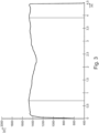
- Figure 4 shows an embodiment in which the carrier 10 has an inner and two oppositely arranged outer regions along its thickness d, a density gradient being present along the thickness d of the carrier such that the inner region has a lower density than the two outer regions , wherein the two outer regions have a substantially constant density.
- the outer area extends within a thickness of approximately 1.6mm to 3.2mm, with the outer areas having a substantially constant density of approximately 1500 kg/m 3 . In between there is a density minimum with significantly reduced density.
Landscapes
- Engineering & Computer Science (AREA)
- Life Sciences & Earth Sciences (AREA)
- Wood Science & Technology (AREA)
- Mechanical Engineering (AREA)
- Finishing Walls (AREA)
- Laminated Bodies (AREA)
Claims (10)
- Support à base de matière plastique pour un panneau de mur ou de sol (18) décoré, présentant un matériau support (12) avec un matériau de matrice thermoplastique dans lequel un matériau solide est incorporé, où le support (10) présente une longueur (1), une largeur (b) et une épaisseur (d), où le support (10) présente, sur son épaisseur (d), à partir d'une surface inférieure (14) jusqu'à une surface supérieure (16), disposée à l'opposé de la surface inférieure (14), un gradient de densité de telle sorte que la densité moyennée du matériau support (12), sur une largeur (b) définie ou une longueur (l) définie d'au moins 5 mm, de préférence, d'au moins 20 mm, diminue d'abord à partir de la surface inférieure (14) jusqu'à la surface supérieure (16) et augmente de nouveau ensuite, caractérisé en ce que la densité sur l'épaisseur (d) du support (10) diminue d'un équivalent dans la plage de > 0 % à ≤ 30 %, de préférence, > 2 % à < 17 %, où lesdites valeurs se rapportent à un maximum de densité et à un minimum de densité sur l'épaisseur (d) et que le matériau solide présente une taille particulaire inférieure ou égale à 800 µm,
- Support selon la revendication 1, caractérisé en ce que le gradient de densité se présente de telle manière que la densité diminue tout d'abord à partir de la surface inférieure (14) jusqu'à la surface supérieure (16) d'au moins trois, de préférence, d'au moins cinq échelles de mesure successives et augmente ensuite d'au moins trois, de préférence, d'au moins cinq échelles de mesure successives.
- Support selon la revendication 1 ou la revendication 2, caractérisé en ce que le gradient de densité est créé par un volume de gaz variable renfermé sur l'épaisseur (d) du support (10).
- Support selon l'une des revendications 1 à 3, caractérisé en ce que le gradient de densité est créée par une teneur en produit solide variable sur l'épaisseur (d) du support (10).
- Support selon l'une des revendications 1 à 4, caractérisé en ce que le support (10) est construit à base d'une multiplicité de couches sur l'épaisseur de telle sorte qu'au moins trois, environ au moins cinq couches sont présentes sur l'épaisseur.
- Support selon l'une des revendications 1 à 5, caractérisé en ce qu'un colorant, notamment sous forme de pigment, est présent dans une couche présentant la surface supérieure (16).
- Support selon l'une des revendications 1 à 6, caractérisé en ce qu'un matériau de recyclage est incorporé au moins dans une couche centrale.
- Support selon l'une des revendications 1 à 7, caractérisé en ce qu'au moins une couche extérieure est munie d'un retardant de flamme.
- Support selon l'une des revendications 1 à 8, caractérisé en ce qu'au moins une couche extérieure est munie d'un inhibiteur d'odeurs.
- Panneau décoré, en particulier panneau de mur ou de sol (18) décoré, présentant un support (10) et une couche de décoration (22) rapportée sur le support (10), en particulier, où une couche de revêtement (24) munie d'une structure est rapportée sur la couche de décoration (22), caractérisé en ce que le support (10) est un support (10) selon l'une des revendications 1 à 9.
Applications Claiming Priority (2)
| Application Number | Priority Date | Filing Date | Title |
|---|---|---|---|
| EP17150300.6A EP3345774B1 (fr) | 2017-01-04 | 2017-01-04 | Procédé de fabrication d'un panneau mural ou de sol décoré |
| PCT/EP2017/084829 WO2018127460A1 (fr) | 2017-01-04 | 2017-12-29 | Support à base de matière plastique pour panneau de mur ou de plancher décoré, et son procédé de fabrication |
Publications (2)
| Publication Number | Publication Date |
|---|---|
| EP3565724A1 EP3565724A1 (fr) | 2019-11-13 |
| EP3565724B1 true EP3565724B1 (fr) | 2024-02-14 |
Family
ID=57758490
Family Applications (2)
| Application Number | Title | Priority Date | Filing Date |
|---|---|---|---|
| EP17150300.6A Active EP3345774B1 (fr) | 2017-01-04 | 2017-01-04 | Procédé de fabrication d'un panneau mural ou de sol décoré |
| EP17826257.2A Active EP3565724B1 (fr) | 2017-01-04 | 2017-12-29 | Support à base de matière plastique pour panneau de mur ou de plancher décoré |
Family Applications Before (1)
| Application Number | Title | Priority Date | Filing Date |
|---|---|---|---|
| EP17150300.6A Active EP3345774B1 (fr) | 2017-01-04 | 2017-01-04 | Procédé de fabrication d'un panneau mural ou de sol décoré |
Country Status (6)
| Country | Link |
|---|---|
| US (1) | US11186117B2 (fr) |
| EP (2) | EP3345774B1 (fr) |
| ES (1) | ES2978448T3 (fr) |
| PL (2) | PL3345774T3 (fr) |
| PT (1) | PT3565724T (fr) |
| WO (1) | WO2018127460A1 (fr) |
Families Citing this family (2)
| Publication number | Priority date | Publication date | Assignee | Title |
|---|---|---|---|---|
| EP3326835A1 (fr) * | 2016-11-25 | 2018-05-30 | Akzenta Paneele + Profile GmbH | Substrat pour un panneau de sol ou de mur décoré |
| LU100764B1 (en) * | 2018-04-10 | 2019-10-11 | Tarkett Gdl Sa | Floor or wall covering panel with rigid composite core layer |
Family Cites Families (10)
| Publication number | Priority date | Publication date | Assignee | Title |
|---|---|---|---|---|
| DE2523670B2 (de) * | 1975-05-28 | 1978-11-02 | Feldmuehle Ag, 4000 Duesseldorf | Verfahren zum kontinuierlichen Herstellen und gleichzeitigem Beschichten von Spanplatten, die mit mindestens einer Decklage aus kunstharzgetränktem Papier belegt sind |
| DK176116B1 (da) * | 1997-03-18 | 2006-08-14 | Wesser & Dueholm | Fremgangsmåde til fremstilling af spånplader, fiberplader og lignende |
| US6322737B1 (en) * | 1999-03-26 | 2001-11-27 | Curtis D. Beyer | Structural member and structure containing the same |
| WO2006033706A1 (fr) * | 2004-07-30 | 2006-03-30 | Mannington Mills, Inc. | Produits pour sol et procedes de fabrication associes |
| DE102006018277B4 (de) * | 2006-04-20 | 2008-04-17 | Kronotec Ag | Bauplatte und Verfahren zur Herstellung einer Bauplatte |
| US20070256379A1 (en) * | 2006-05-08 | 2007-11-08 | Edwards Christopher M | Composite panels |
| US8956714B2 (en) * | 2007-04-10 | 2015-02-17 | Spanolux N.V.-Div. Balterio | Method and apparatus for manufacturing laminate floor panels comprising a core containing wood/plastic composite, as well as such panels |
| DE102013101795A1 (de) * | 2012-11-23 | 2014-05-28 | Hamberger Industriewerke Gmbh | Tragplatte |
| EP2829415A1 (fr) | 2013-07-22 | 2015-01-28 | Akzenta Paneele + Profile GmbH | Procédé de fabrication d'un panneau mural et de sol décoré |
| PL3147135T3 (pl) * | 2015-09-24 | 2021-06-14 | Akzenta Paneele + Profile Gmbh | Sposób wytwarzania dekoracyjnego panelu ściennego lub podłogowego |
-
2017
- 2017-01-04 PL PL17150300T patent/PL3345774T3/pl unknown
- 2017-01-04 EP EP17150300.6A patent/EP3345774B1/fr active Active
- 2017-12-29 PL PL17826257.2T patent/PL3565724T3/pl unknown
- 2017-12-29 WO PCT/EP2017/084829 patent/WO2018127460A1/fr not_active Ceased
- 2017-12-29 ES ES17826257T patent/ES2978448T3/es active Active
- 2017-12-29 EP EP17826257.2A patent/EP3565724B1/fr active Active
- 2017-12-29 PT PT178262572T patent/PT3565724T/pt unknown
- 2017-12-29 US US16/474,746 patent/US11186117B2/en active Active
Also Published As
| Publication number | Publication date |
|---|---|
| EP3345774B1 (fr) | 2020-11-18 |
| EP3345774A1 (fr) | 2018-07-11 |
| PL3565724T3 (pl) | 2024-06-24 |
| EP3565724A1 (fr) | 2019-11-13 |
| PT3565724T (pt) | 2024-04-22 |
| US20190315153A1 (en) | 2019-10-17 |
| WO2018127460A1 (fr) | 2018-07-12 |
| PL3345774T3 (pl) | 2021-06-14 |
| US11186117B2 (en) | 2021-11-30 |
| ES2978448T3 (es) | 2024-09-12 |
Similar Documents
| Publication | Publication Date | Title |
|---|---|---|
| EP3578384B1 (fr) | Matériau porteur à base d'une composition de matière plastique et d'une composition de matière solide minérales pour panneaux muraux ou de sol décorés | |
| EP3147135B1 (fr) | Procede de fabrication d'un panneau mural ou de sol decore | |
| EP3401115B1 (fr) | Procédé de fabrication d'un panneau mural ou de sol décoré | |
| EP3403846B1 (fr) | Procédé de fabrication d'un panneau mural ou de sol décoré | |
| EP3532300B1 (fr) | Procédé de fabrication d'un panneau mural ou de sol décoré | |
| EP3178652A1 (fr) | Panneau de decoration et son procede de fabrication | |
| EP3837112B1 (fr) | Plaque support en plastique multilaminaire et son procede de production | |
| EP3132945B1 (fr) | Procede de fabrication d'un panneau mural ou de sol decore | |
| EP3565724B1 (fr) | Support à base de matière plastique pour panneau de mur ou de plancher décoré | |
| EP3837110B1 (fr) | Panneau décoratif doté d'une plaque porteuse en matière plastique multilaminaire et son procédé de fabrication | |
| EP3544823A1 (fr) | Matériau de substrat pour panneau mural ou panneau de sol pourvu d'un décor | |
| EP3088204B1 (fr) | Procédé de fabrication d'un panneau mural ou de sol décoré | |
| EP3974176B1 (fr) | Feuille de protection de fermeture pour panneaux décoratifs | |
| EP3536517A1 (fr) | Matériau support à base de minéraux pour panneaux muraux ou de plancher décorés | |
| EP3088205A1 (fr) | Procédé de fabrication d'un panneau mural ou de sol décoré | |
| EP4133144A1 (fr) | Panneau décoratif ayant des bords non parallèles à l'axe longitudinal et procédé de fabrication |
Legal Events
| Date | Code | Title | Description |
|---|---|---|---|
| STAA | Information on the status of an ep patent application or granted ep patent |
Free format text: STATUS: UNKNOWN |
|
| STAA | Information on the status of an ep patent application or granted ep patent |
Free format text: STATUS: THE INTERNATIONAL PUBLICATION HAS BEEN MADE |
|
| PUAI | Public reference made under article 153(3) epc to a published international application that has entered the european phase |
Free format text: ORIGINAL CODE: 0009012 |
|
| STAA | Information on the status of an ep patent application or granted ep patent |
Free format text: STATUS: REQUEST FOR EXAMINATION WAS MADE |
|
| 17P | Request for examination filed |
Effective date: 20190528 |
|
| AK | Designated contracting states |
Kind code of ref document: A1 Designated state(s): AL AT BE BG CH CY CZ DE DK EE ES FI FR GB GR HR HU IE IS IT LI LT LU LV MC MK MT NL NO PL PT RO RS SE SI SK SM TR |
|
| AX | Request for extension of the european patent |
Extension state: BA ME |
|
| DAV | Request for validation of the european patent (deleted) | ||
| DAX | Request for extension of the european patent (deleted) | ||
| STAA | Information on the status of an ep patent application or granted ep patent |
Free format text: STATUS: EXAMINATION IS IN PROGRESS |
|
| 17Q | First examination report despatched |
Effective date: 20211215 |
|
| P01 | Opt-out of the competence of the unified patent court (upc) registered |
Effective date: 20230526 |
|
| GRAP | Despatch of communication of intention to grant a patent |
Free format text: ORIGINAL CODE: EPIDOSNIGR1 |
|
| STAA | Information on the status of an ep patent application or granted ep patent |
Free format text: STATUS: GRANT OF PATENT IS INTENDED |
|
| INTG | Intention to grant announced |
Effective date: 20231010 |
|
| GRAS | Grant fee paid |
Free format text: ORIGINAL CODE: EPIDOSNIGR3 |
|
| GRAA | (expected) grant |
Free format text: ORIGINAL CODE: 0009210 |
|
| STAA | Information on the status of an ep patent application or granted ep patent |
Free format text: STATUS: THE PATENT HAS BEEN GRANTED |
|
| AK | Designated contracting states |
Kind code of ref document: B1 Designated state(s): AL AT BE BG CH CY CZ DE DK EE ES FI FR GB GR HR HU IE IS IT LI LT LU LV MC MK MT NL NO PL PT RO RS SE SI SK SM TR |
|
| REG | Reference to a national code |
Ref country code: GB Ref legal event code: FG4D Free format text: NOT ENGLISH |
|
| REG | Reference to a national code |
Ref country code: CH Ref legal event code: EP |
|
| REG | Reference to a national code |
Ref country code: DE Ref legal event code: R096 Ref document number: 502017015837 Country of ref document: DE |
|
| REG | Reference to a national code |
Ref country code: IE Ref legal event code: FG4D Free format text: LANGUAGE OF EP DOCUMENT: GERMAN |
|
| REG | Reference to a national code |
Ref country code: NL Ref legal event code: FP |
|
| REG | Reference to a national code |
Ref country code: PT Ref legal event code: SC4A Ref document number: 3565724 Country of ref document: PT Date of ref document: 20240422 Kind code of ref document: T Free format text: AVAILABILITY OF NATIONAL TRANSLATION Effective date: 20240416 |
|
| REG | Reference to a national code |
Ref country code: LT Ref legal event code: MG9D |
|
| PG25 | Lapsed in a contracting state [announced via postgrant information from national office to epo] |
Ref country code: IS Free format text: LAPSE BECAUSE OF FAILURE TO SUBMIT A TRANSLATION OF THE DESCRIPTION OR TO PAY THE FEE WITHIN THE PRESCRIBED TIME-LIMIT Effective date: 20240614 |
|
| PG25 | Lapsed in a contracting state [announced via postgrant information from national office to epo] |
Ref country code: LT Free format text: LAPSE BECAUSE OF FAILURE TO SUBMIT A TRANSLATION OF THE DESCRIPTION OR TO PAY THE FEE WITHIN THE PRESCRIBED TIME-LIMIT Effective date: 20240214 |
|
| PG25 | Lapsed in a contracting state [announced via postgrant information from national office to epo] |
Ref country code: GR Free format text: LAPSE BECAUSE OF FAILURE TO SUBMIT A TRANSLATION OF THE DESCRIPTION OR TO PAY THE FEE WITHIN THE PRESCRIBED TIME-LIMIT Effective date: 20240515 |
|
| PG25 | Lapsed in a contracting state [announced via postgrant information from national office to epo] |
Ref country code: RS Free format text: LAPSE BECAUSE OF FAILURE TO SUBMIT A TRANSLATION OF THE DESCRIPTION OR TO PAY THE FEE WITHIN THE PRESCRIBED TIME-LIMIT Effective date: 20240514 Ref country code: HR Free format text: LAPSE BECAUSE OF FAILURE TO SUBMIT A TRANSLATION OF THE DESCRIPTION OR TO PAY THE FEE WITHIN THE PRESCRIBED TIME-LIMIT Effective date: 20240214 |
|
| PG25 | Lapsed in a contracting state [announced via postgrant information from national office to epo] |
Ref country code: RS Free format text: LAPSE BECAUSE OF FAILURE TO SUBMIT A TRANSLATION OF THE DESCRIPTION OR TO PAY THE FEE WITHIN THE PRESCRIBED TIME-LIMIT Effective date: 20240514 Ref country code: NO Free format text: LAPSE BECAUSE OF FAILURE TO SUBMIT A TRANSLATION OF THE DESCRIPTION OR TO PAY THE FEE WITHIN THE PRESCRIBED TIME-LIMIT Effective date: 20240514 Ref country code: LT Free format text: LAPSE BECAUSE OF FAILURE TO SUBMIT A TRANSLATION OF THE DESCRIPTION OR TO PAY THE FEE WITHIN THE PRESCRIBED TIME-LIMIT Effective date: 20240214 Ref country code: IS Free format text: LAPSE BECAUSE OF FAILURE TO SUBMIT A TRANSLATION OF THE DESCRIPTION OR TO PAY THE FEE WITHIN THE PRESCRIBED TIME-LIMIT Effective date: 20240614 Ref country code: HR Free format text: LAPSE BECAUSE OF FAILURE TO SUBMIT A TRANSLATION OF THE DESCRIPTION OR TO PAY THE FEE WITHIN THE PRESCRIBED TIME-LIMIT Effective date: 20240214 Ref country code: GR Free format text: LAPSE BECAUSE OF FAILURE TO SUBMIT A TRANSLATION OF THE DESCRIPTION OR TO PAY THE FEE WITHIN THE PRESCRIBED TIME-LIMIT Effective date: 20240515 Ref country code: FI Free format text: LAPSE BECAUSE OF FAILURE TO SUBMIT A TRANSLATION OF THE DESCRIPTION OR TO PAY THE FEE WITHIN THE PRESCRIBED TIME-LIMIT Effective date: 20240214 Ref country code: BG Free format text: LAPSE BECAUSE OF FAILURE TO SUBMIT A TRANSLATION OF THE DESCRIPTION OR TO PAY THE FEE WITHIN THE PRESCRIBED TIME-LIMIT Effective date: 20240214 |
|
| PG25 | Lapsed in a contracting state [announced via postgrant information from national office to epo] |
Ref country code: SE Free format text: LAPSE BECAUSE OF FAILURE TO SUBMIT A TRANSLATION OF THE DESCRIPTION OR TO PAY THE FEE WITHIN THE PRESCRIBED TIME-LIMIT Effective date: 20240214 Ref country code: LV Free format text: LAPSE BECAUSE OF FAILURE TO SUBMIT A TRANSLATION OF THE DESCRIPTION OR TO PAY THE FEE WITHIN THE PRESCRIBED TIME-LIMIT Effective date: 20240214 |
|
| REG | Reference to a national code |
Ref country code: ES Ref legal event code: FG2A Ref document number: 2978448 Country of ref document: ES Kind code of ref document: T3 Effective date: 20240912 |
|
| PG25 | Lapsed in a contracting state [announced via postgrant information from national office to epo] |
Ref country code: DK Free format text: LAPSE BECAUSE OF FAILURE TO SUBMIT A TRANSLATION OF THE DESCRIPTION OR TO PAY THE FEE WITHIN THE PRESCRIBED TIME-LIMIT Effective date: 20240214 |
|
| PG25 | Lapsed in a contracting state [announced via postgrant information from national office to epo] |
Ref country code: SM Free format text: LAPSE BECAUSE OF FAILURE TO SUBMIT A TRANSLATION OF THE DESCRIPTION OR TO PAY THE FEE WITHIN THE PRESCRIBED TIME-LIMIT Effective date: 20240214 |
|
| PG25 | Lapsed in a contracting state [announced via postgrant information from national office to epo] |
Ref country code: EE Free format text: LAPSE BECAUSE OF FAILURE TO SUBMIT A TRANSLATION OF THE DESCRIPTION OR TO PAY THE FEE WITHIN THE PRESCRIBED TIME-LIMIT Effective date: 20240214 Ref country code: CZ Free format text: LAPSE BECAUSE OF FAILURE TO SUBMIT A TRANSLATION OF THE DESCRIPTION OR TO PAY THE FEE WITHIN THE PRESCRIBED TIME-LIMIT Effective date: 20240214 |
|
| PG25 | Lapsed in a contracting state [announced via postgrant information from national office to epo] |
Ref country code: SK Free format text: LAPSE BECAUSE OF FAILURE TO SUBMIT A TRANSLATION OF THE DESCRIPTION OR TO PAY THE FEE WITHIN THE PRESCRIBED TIME-LIMIT Effective date: 20240214 |
|
| PG25 | Lapsed in a contracting state [announced via postgrant information from national office to epo] |
Ref country code: SM Free format text: LAPSE BECAUSE OF FAILURE TO SUBMIT A TRANSLATION OF THE DESCRIPTION OR TO PAY THE FEE WITHIN THE PRESCRIBED TIME-LIMIT Effective date: 20240214 Ref country code: SK Free format text: LAPSE BECAUSE OF FAILURE TO SUBMIT A TRANSLATION OF THE DESCRIPTION OR TO PAY THE FEE WITHIN THE PRESCRIBED TIME-LIMIT Effective date: 20240214 Ref country code: RO Free format text: LAPSE BECAUSE OF FAILURE TO SUBMIT A TRANSLATION OF THE DESCRIPTION OR TO PAY THE FEE WITHIN THE PRESCRIBED TIME-LIMIT Effective date: 20240214 Ref country code: EE Free format text: LAPSE BECAUSE OF FAILURE TO SUBMIT A TRANSLATION OF THE DESCRIPTION OR TO PAY THE FEE WITHIN THE PRESCRIBED TIME-LIMIT Effective date: 20240214 Ref country code: DK Free format text: LAPSE BECAUSE OF FAILURE TO SUBMIT A TRANSLATION OF THE DESCRIPTION OR TO PAY THE FEE WITHIN THE PRESCRIBED TIME-LIMIT Effective date: 20240214 Ref country code: CZ Free format text: LAPSE BECAUSE OF FAILURE TO SUBMIT A TRANSLATION OF THE DESCRIPTION OR TO PAY THE FEE WITHIN THE PRESCRIBED TIME-LIMIT Effective date: 20240214 |
|
| REG | Reference to a national code |
Ref country code: DE Ref legal event code: R097 Ref document number: 502017015837 Country of ref document: DE |
|
| PG25 | Lapsed in a contracting state [announced via postgrant information from national office to epo] |
Ref country code: IT Free format text: LAPSE BECAUSE OF FAILURE TO SUBMIT A TRANSLATION OF THE DESCRIPTION OR TO PAY THE FEE WITHIN THE PRESCRIBED TIME-LIMIT Effective date: 20240214 |
|
| PLBE | No opposition filed within time limit |
Free format text: ORIGINAL CODE: 0009261 |
|
| STAA | Information on the status of an ep patent application or granted ep patent |
Free format text: STATUS: NO OPPOSITION FILED WITHIN TIME LIMIT |
|
| PG25 | Lapsed in a contracting state [announced via postgrant information from national office to epo] |
Ref country code: IT Free format text: LAPSE BECAUSE OF FAILURE TO SUBMIT A TRANSLATION OF THE DESCRIPTION OR TO PAY THE FEE WITHIN THE PRESCRIBED TIME-LIMIT Effective date: 20240214 |
|
| 26N | No opposition filed |
Effective date: 20241115 |
|
| PG25 | Lapsed in a contracting state [announced via postgrant information from national office to epo] |
Ref country code: SI Free format text: LAPSE BECAUSE OF FAILURE TO SUBMIT A TRANSLATION OF THE DESCRIPTION OR TO PAY THE FEE WITHIN THE PRESCRIBED TIME-LIMIT Effective date: 20240214 |
|
| PG25 | Lapsed in a contracting state [announced via postgrant information from national office to epo] |
Ref country code: MC Free format text: LAPSE BECAUSE OF FAILURE TO SUBMIT A TRANSLATION OF THE DESCRIPTION OR TO PAY THE FEE WITHIN THE PRESCRIBED TIME-LIMIT Effective date: 20240214 |
|
| REG | Reference to a national code |
Ref country code: CH Ref legal event code: PL |
|
| PG25 | Lapsed in a contracting state [announced via postgrant information from national office to epo] |
Ref country code: LU Free format text: LAPSE BECAUSE OF NON-PAYMENT OF DUE FEES Effective date: 20241229 |
|
| PG25 | Lapsed in a contracting state [announced via postgrant information from national office to epo] |
Ref country code: CH Free format text: LAPSE BECAUSE OF NON-PAYMENT OF DUE FEES Effective date: 20241231 |
|
| PG25 | Lapsed in a contracting state [announced via postgrant information from national office to epo] |
Ref country code: IE Free format text: LAPSE BECAUSE OF NON-PAYMENT OF DUE FEES Effective date: 20241229 |
|
| PGFP | Annual fee paid to national office [announced via postgrant information from national office to epo] |
Ref country code: DE Payment date: 20251217 Year of fee payment: 9 |
|
| PGFP | Annual fee paid to national office [announced via postgrant information from national office to epo] |
Ref country code: GB Payment date: 20251219 Year of fee payment: 9 |
|
| PGFP | Annual fee paid to national office [announced via postgrant information from national office to epo] |
Ref country code: AT Payment date: 20251222 Year of fee payment: 9 Ref country code: PT Payment date: 20251219 Year of fee payment: 9 |
|
| PGFP | Annual fee paid to national office [announced via postgrant information from national office to epo] |
Ref country code: FR Payment date: 20251229 Year of fee payment: 9 Ref country code: NL Payment date: 20251219 Year of fee payment: 9 |
|
| PGFP | Annual fee paid to national office [announced via postgrant information from national office to epo] |
Ref country code: TR Payment date: 20251224 Year of fee payment: 9 Ref country code: BE Payment date: 20251219 Year of fee payment: 9 |
|
| PGFP | Annual fee paid to national office [announced via postgrant information from national office to epo] |
Ref country code: PL Payment date: 20251119 Year of fee payment: 9 |
|
| PGFP | Annual fee paid to national office [announced via postgrant information from national office to epo] |
Ref country code: ES Payment date: 20260130 Year of fee payment: 9 |