EP3571008B1 - Procédé et dispositif permettant de déterminer et/ou de surveiller l'état d'un capot de protection - Google Patents
Procédé et dispositif permettant de déterminer et/ou de surveiller l'état d'un capot de protection Download PDFInfo
- Publication number
- EP3571008B1 EP3571008B1 EP18702421.1A EP18702421A EP3571008B1 EP 3571008 B1 EP3571008 B1 EP 3571008B1 EP 18702421 A EP18702421 A EP 18702421A EP 3571008 B1 EP3571008 B1 EP 3571008B1
- Authority
- EP
- European Patent Office
- Prior art keywords
- protective cover
- state
- time
- point
- value
- Prior art date
- Legal status (The legal status is an assumption and is not a legal conclusion. Google has not performed a legal analysis and makes no representation as to the accuracy of the status listed.)
- Active
Links
Images


Classifications
-
- B—PERFORMING OPERATIONS; TRANSPORTING
- B23—MACHINE TOOLS; METAL-WORKING NOT OTHERWISE PROVIDED FOR
- B23Q—DETAILS, COMPONENTS, OR ACCESSORIES FOR MACHINE TOOLS, e.g. ARRANGEMENTS FOR COPYING OR CONTROLLING; MACHINE TOOLS IN GENERAL CHARACTERISED BY THE CONSTRUCTION OF PARTICULAR DETAILS OR COMPONENTS; COMBINATIONS OR ASSOCIATIONS OF METAL-WORKING MACHINES, NOT DIRECTED TO A PARTICULAR RESULT
- B23Q11/00—Accessories fitted to machine tools for keeping tools or parts of the machine in good working condition or for cooling work; Safety devices specially combined with or arranged in, or specially adapted for use in connection with, machine tools
- B23Q11/08—Protective coverings for parts of machine tools; Splash guards
-
- B—PERFORMING OPERATIONS; TRANSPORTING
- B23—MACHINE TOOLS; METAL-WORKING NOT OTHERWISE PROVIDED FOR
- B23Q—DETAILS, COMPONENTS, OR ACCESSORIES FOR MACHINE TOOLS, e.g. ARRANGEMENTS FOR COPYING OR CONTROLLING; MACHINE TOOLS IN GENERAL CHARACTERISED BY THE CONSTRUCTION OF PARTICULAR DETAILS OR COMPONENTS; COMBINATIONS OR ASSOCIATIONS OF METAL-WORKING MACHINES, NOT DIRECTED TO A PARTICULAR RESULT
- B23Q11/00—Accessories fitted to machine tools for keeping tools or parts of the machine in good working condition or for cooling work; Safety devices specially combined with or arranged in, or specially adapted for use in connection with, machine tools
- B23Q11/08—Protective coverings for parts of machine tools; Splash guards
- B23Q11/0891—Protective coverings for parts of machine tools; Splash guards arranged between the working area and the operator
-
- B—PERFORMING OPERATIONS; TRANSPORTING
- B23—MACHINE TOOLS; METAL-WORKING NOT OTHERWISE PROVIDED FOR
- B23Q—DETAILS, COMPONENTS, OR ACCESSORIES FOR MACHINE TOOLS, e.g. ARRANGEMENTS FOR COPYING OR CONTROLLING; MACHINE TOOLS IN GENERAL CHARACTERISED BY THE CONSTRUCTION OF PARTICULAR DETAILS OR COMPONENTS; COMBINATIONS OR ASSOCIATIONS OF METAL-WORKING MACHINES, NOT DIRECTED TO A PARTICULAR RESULT
- B23Q11/00—Accessories fitted to machine tools for keeping tools or parts of the machine in good working condition or for cooling work; Safety devices specially combined with or arranged in, or specially adapted for use in connection with, machine tools
- B23Q11/08—Protective coverings for parts of machine tools; Splash guards
- B23Q11/0816—Foldable coverings, e.g. bellows
-
- B—PERFORMING OPERATIONS; TRANSPORTING
- B23—MACHINE TOOLS; METAL-WORKING NOT OTHERWISE PROVIDED FOR
- B23Q—DETAILS, COMPONENTS, OR ACCESSORIES FOR MACHINE TOOLS, e.g. ARRANGEMENTS FOR COPYING OR CONTROLLING; MACHINE TOOLS IN GENERAL CHARACTERISED BY THE CONSTRUCTION OF PARTICULAR DETAILS OR COMPONENTS; COMBINATIONS OR ASSOCIATIONS OF METAL-WORKING MACHINES, NOT DIRECTED TO A PARTICULAR RESULT
- B23Q11/00—Accessories fitted to machine tools for keeping tools or parts of the machine in good working condition or for cooling work; Safety devices specially combined with or arranged in, or specially adapted for use in connection with, machine tools
- B23Q11/08—Protective coverings for parts of machine tools; Splash guards
- B23Q11/0825—Relatively slidable coverings, e.g. telescopic
-
- B—PERFORMING OPERATIONS; TRANSPORTING
- B23—MACHINE TOOLS; METAL-WORKING NOT OTHERWISE PROVIDED FOR
- B23Q—DETAILS, COMPONENTS, OR ACCESSORIES FOR MACHINE TOOLS, e.g. ARRANGEMENTS FOR COPYING OR CONTROLLING; MACHINE TOOLS IN GENERAL CHARACTERISED BY THE CONSTRUCTION OF PARTICULAR DETAILS OR COMPONENTS; COMBINATIONS OR ASSOCIATIONS OF METAL-WORKING MACHINES, NOT DIRECTED TO A PARTICULAR RESULT
- B23Q17/00—Arrangements for observing, indicating or measuring on machine tools
- B23Q17/007—Arrangements for observing, indicating or measuring on machine tools for managing machine functions not concerning the tool
-
- B—PERFORMING OPERATIONS; TRANSPORTING
- B23—MACHINE TOOLS; METAL-WORKING NOT OTHERWISE PROVIDED FOR
- B23Q—DETAILS, COMPONENTS, OR ACCESSORIES FOR MACHINE TOOLS, e.g. ARRANGEMENTS FOR COPYING OR CONTROLLING; MACHINE TOOLS IN GENERAL CHARACTERISED BY THE CONSTRUCTION OF PARTICULAR DETAILS OR COMPONENTS; COMBINATIONS OR ASSOCIATIONS OF METAL-WORKING MACHINES, NOT DIRECTED TO A PARTICULAR RESULT
- B23Q17/00—Arrangements for observing, indicating or measuring on machine tools
- B23Q17/007—Arrangements for observing, indicating or measuring on machine tools for managing machine functions not concerning the tool
- B23Q17/008—Life management for parts of the machine
-
- F—MECHANICAL ENGINEERING; LIGHTING; HEATING; WEAPONS; BLASTING
- F16—ENGINEERING ELEMENTS AND UNITS; GENERAL MEASURES FOR PRODUCING AND MAINTAINING EFFECTIVE FUNCTIONING OF MACHINES OR INSTALLATIONS; THERMAL INSULATION IN GENERAL
- F16P—SAFETY DEVICES IN GENERAL; SAFETY DEVICES FOR PRESSES
- F16P3/00—Safety devices acting in conjunction with the control or operation of a machine; Control arrangements requiring the simultaneous use of two or more parts of the body
- F16P3/02—Screens or other safety members moving in synchronism with members which move to and fro
Definitions
- the invention relates to a method and a device for determining and / or monitoring the state of a protective cover.
- Protective covers are already known from the prior art and are used in particular, but by no means exclusively, to cover moving machine parts or the like.
- US 2014/150533 A1 discloses a method and a device for determining and / or monitoring the state of a protective cover designed as a sliding door with a window, a characteristic property (compressive force or pressure load) of the protective cover being detected.
- Such protective covers typically have elements that can be changed in length in order to cover the machine parts in this way both in the retracted and in the extended state. In this way, the machine parts are not only protected from external influences, such as chips, dust particles or other contamination, but can also be sealed off from the environment.
- the DE 10 2006 033 607 B4 and the DE 20 2012 008 987 U1 to call are not only protected from external influences, such as chips, dust particles or other contamination, but can also be sealed off from the environment.
- the elements of the protective cover that are variable in length are connected to a support frame, which serves to stabilize them, in particular to support them.
- a support frame in turn comprises a plurality of frame elements which are evenly spaced from one another over the length of the elements of the protective cover and which can also be connected to the elements. The connection of the support frame and / or the frame elements with the elements of the protective cover is used to ensure the functionality and / or the protective function of the protective cover.
- the invention has therefore set itself the task of providing a method and a device for determining and / or monitoring the state of a protective cover in order to overcome the above-mentioned difficulties and, above all, to optimally plan the maintenance and / or repair-related work in order to thereby reducing machine downtimes and the resulting costs to a minimum.
- the method according to the invention is based on the basic idea that it is sufficient to determine and / or monitor the state of a protective cover to record at least two state values of at least two characteristic physical, mechanical and / or chemical properties of this protective cover, in particular at two subsequent times, and to determine and / or monitor the condition of the protective cover with sufficient accuracy based on the comparison of these condition values.
- a change in the characteristic property can preferably be an improvement and / or a deterioration of this.
- the term "characteristic property" relates to a property that is essential for the material used, the intended use, the place of use and / or the conditions of use of the protective cover, by means of which a direct or indirect conclusion about the condition of the protective cover is possible.
- the tightness of a protective cover is essential in the case of a dust- and / or moisture-tight protective cover. It is important that the characteristic property is examined, known and / or defined with sufficient accuracy, in particular its change over time, preferably the usage time, the idle time and / or the downtime. This means that the functional relationship of the characteristic property between the change and time is known and / or defined.
- the functional relationship can be represented, for example, but by no means exclusively, in a function as a trend with a state value curve over time, for example in a linear function, in a logarithmic function, in an exponential function, in a logistic function, in a polygonal function and / or a mixture of these.
- the first and the second state value of the same characteristic property or the same characteristic properties are recorded. It is also conceivable that the state values of the two characteristic properties are recorded in combination with at least one further value for a factor which is related to the material used, the purpose, the place of use and / or the conditions of use of the protective cover. Even more preferably with values for 3, 4, 5, 6, 7, 8, 9, 10, 11, 12, 13, 14, 15, 16, 17, 18, 19, 20 or more factors. The reason for this is that a characteristic property is dependent on and / or can be influenced by various factors, the additional detection of which contributes to an improvement in the determination and / or monitoring. For example, in this context the temperature, the pressure and / or the humidity are conceivable, which can affect the characteristic properties of the protective cover.
- the term “method for determining and / or monitoring the state of a protective cover” relates to a method for determining the change, preferably an improvement and / or a deterioration, of the characteristic physical, mechanical and / or chemical property of the protective cover over time, preferably the Usage time, the downtime and / or the downtime, by means of which a statement can be made about damage, maintenance, failure, repair, age, wear and / or the remaining useful life of the protective cover.
- the development and / or cause of damage can be shown so that an upcoming maintenance interval can be planned and / or predicted in the best possible way.
- the method according to the invention can contain additional steps which are after or between the essential steps a) to d) explicitly listed.
- the method can preferably be automated.
- protective cover relates in particular, but by no means exclusively, to a cover for moving machine parts or the like.
- the term denotes the entire protective cover, a region thereof and / or at least one element thereof.
- the term “determination of the state” of the protective cover relates to the determination of the state based on the detection of the at least one characteristic physical, mechanical and / or chemical property of the protective cover, which is preferably carried out by means of a suitable means.
- the determination is preferably carried out semiquantitatively, quantitatively, directly and / or indirectly.
- a direct determination relates, for example, to the detection of the state of the characteristic property of the protective cover based on a signal and / or value which is derived directly from the protective cover.
- Such a signal and / or such a value can be obtained in various ways, for example by detecting at least one physical, mechanical and / or chemical property of the protective cover using means known from the prior art.
- the indirect determination relates, for example, to the detection of a signal and / or value of the characteristic property of the protective cover, which is obtained via an additional or secondary component.
- the term “monitoring of the state” relates to the tracking and / or the prediction of the determined state of the at least one characteristic physical, mechanical and / or chemical property of the protective cover.
- the monitoring can be represented, for example, but by no means exclusively numerically and / or graphically. In order to increase the accuracy of the monitoring, this preferably takes place at several times and / or permanently. The advantage of longer-term monitoring is that it is also easier to predict the condition of the protective cover.
- a determination and / or a monitoring can generally not be 100 percent correct.
- the term therefore relates to a statistically significant probability with regard to the accuracy of the determination of the state or the tracking and / or prediction of the determined state. Whether such a determination and / or monitoring is statistically significant can be determined by a person skilled in the art by means of methods known to those skilled in the art, without being inventive. For example, statistical evaluation tools should be mentioned, such as the determination of the confidence interval, the p-value, the Student's t-test, the Mann-Whitney determination, etc.
- the corresponding intervals are at least 90%, at least 95%, at least 97% , at least 98% or at least 99% correct.
- the p-values are preferably 0.1, 0.05, 0.01, 0.005 or 0.0001.
- the determination of the state of the protective cover and / or the monitoring of the determined state is preferably at least 60%, at least 70%, at least 80%, at least 90% or at least 95% or at least 99% correct.
- the term “compare” relates to the comparison of the status values with one another, in particular the first and the second status value of the at least one characteristic physical, mechanical and / or chemical property of the protective cover. It goes without saying that a comparison as used here relates to a comparison of corresponding parameters and / or values. For example, it is conceivable that an absolute first status value is comparable to an absolute second status value, a relative value of the first status value being comparable to a relative value of the second status value. Furthermore, it is conceivable that an intensity signal of the first status value is comparable to an intensity signal of the second status value.
- the comparison can be carried out manually and / or with the aid of a computer.
- a computer-aided comparison for example of the state values recorded in steps a) and b
- all means known to a person skilled in the art are conceivable, such as a computer and / or a computer program.
- a computer program can also evaluate the result of the comparison, for example automatically deliver an assessment of the recorded status values.
- a determination of the state of the protective cover is possible by means of the comparison carried out in step c). It is also conceivable, for example, that steps c) and d) are supported by an evaluation, an analysis and / or an evaluation unit. The point in time at which the status value of the characteristic property of the protective cover is recorded is also taken into account in the comparison, so that a prediction is made based on the comparison it can be determined how the state changes over time.
- the first and the second status value of the same characteristic property or the same characteristic properties between several protective covers ie between 2, 3, 4, 5, 6, 7, 8, 9, 10, 11 , 12, 13, 14, 15, 16, 17, 18, 19, 20 or more protective covers. It is understandable here that the determination and / or monitoring of the state of each individual protective cover takes place primarily in order to compare several protective covers with one another on the basis of this.
- the state of the protective cover is not only determined and / or monitored as a function of time, ie a temporal change in the first and second state values of the same characteristic property or the same characteristic properties of the same protective cover, but also the determination and / or or the state of the protective cover is monitored in a spatial relationship, ie a change in the first and the second state value of the same characteristic property or the same characteristic properties between different protective covers.
- spatial relates on the one hand to the comparison of protective covers arranged directly next to, below and / or above one another, and on the other hand to protective covers which are arranged at any distance from one another.
- the spatial dependency comparison offers the advantage that in this way conclusions can be drawn about the change in the state of the protective covers as a function of the respective conditions at the installation and / or operating site.
- the result of the comparison is directly or indirectly dependent on the characteristic property. It is thus conceivable that a small and insignificant, large and significant and / or no change in the second status value compared to the first status value is indicative of a specific status. A change in the characteristic property can preferably be an improvement and / or a deterioration of this. In this context, it is conceivable that the result of the comparison can be output as a time specification, for example in years, months, days, hours and / or minutes, an absolute value and / or a relative value.
- the result of the comparison is an extension of the time specified for each individual protective cover, in this way, for example, conclusions about the change in the characteristic properties of the respective protective covers depending on the prevailing conditions at the installation and / or operating site to pull.
- This offers the advantage that the condition influencing the characteristic property can be determined and / or monitored.
- Step e) can be supported by an output unit.
- the acquisition of a third status value offers the advantage that a better approximation of the functional relationship of the characteristic property and thus a drastic improvement of the determination in step d) can be achieved.
- a better statement can be made about the curvature of the function, it being the case that the accuracy of the determination in step d) increases with an increasing number of acquired state values.
- the first state value of the characteristic property is a reference value.
- the reference value can in particular, but by no means exclusively, be a fixed, determined and / or theoretical value, such as a laboratory value and / or a database entry, and can be recorded before and / or when the protective cover is put into operation.
- the reference value defines a threshold value which is preferably defined as the upper limit of the normal value of the characteristic physical, mechanical and / or chemical property under various conditions. The value of the upper limit of normal can be determined by various techniques well known to a person skilled in the art.
- the first, the second and / or the third state value is recorded under essentially similar conditions. This significantly increases the accuracy of the determination and / or monitoring of the state of the protective cover, in particular through a partial or complete exclusion of various factors on which the characteristic property is dependent and / or can be influenced.
- the term "substantially similar” means that there is only a slight, especially insignificant, change, change and / or deviation from the conditions occurs during the state value detection.
- the first, the second and / or the third state value is recorded under different conditions.
- the detection of the status values under different conditions i.e. under different conditions, enables the dependence and / or influence of the characteristic property on various factors, such as temperature, pressure and / or humidity, to be determined.
- the characteristic properties are the light transmission, the light absorption, the light reflection, the viscosity, the acceleration, the speed, the elasticity, the rigidity, the temperature, the moisture content, the electrical conductivity, the compressive force, the compressive load, the tensile load, the pretensioning force , porosity, weight, fragility, thickness and / or density.
- the state of the protective cover is selected from the list from the remaining service life, the state of aging, wear, the presence of damage and / or the impending maintenance interval.
- the term "remaining useful life” relates to the determination of the remaining time of the protective cover, in which the functionality and / or protective function of it exists. By determining this value, it is also possible, for example, to determine and / or monitor when the protective cover is to be serviced, repaired and / or replaced. It can also be monitored, for example, how the functionality and / or protective function of the protective cover over the Time changed.
- the remaining useful life can preferably be represented in the form of a time unit, for example in years, months, days, hours and / or minutes, and as a relative value.
- state of aging and “wear and tear” describe, for example, a determination of the maximum age, functionality and / or protective function of the protective cover and / or the probability of failure of the protective cover. Using these values, it is possible, for example, to draw conclusions about when maintenance, repair and / or replacement is useful and / or necessary in order to ensure that there are no aging-related failures of the protective cover and thus no unplanned downtime of the machine comes.
- the state of aging and / or wear can preferably be represented in the form of a time unit, for example in years, months, days, hours and / or minutes, and as a relative value.
- Presence of damage relates to determining whether or not the protective cover is damaged. This is conceivable, for example, in that there is a significant and / or atypical change in the functional relationship known and / or defined for the characteristic property, in particular the function.
- the presence of damage can preferably be represented graphically and / or in the form of an absolute value.
- the term “imminent maintenance interval” relates to the determination of the remaining time of the protective cover until it has to be serviced, repaired and / or replaced. It can also be monitored, for example, how the functionality and / or protective function of the protective cover changes over time.
- the impending maintenance interval can preferably be represented in the form of a time unit, for example in years, months, days, hours and / or minutes, and as a relative value.
- the protective cover comprises at least one protective cover element variable in length, a support frame, at least one frame element and / or a lock variable in length.
- the protective cover typically has at least one length-adjustable protective cover element in order to protect the machine parts from external influences, such as chips, dust particles or other contamination, both in the retracted and in the extended state, and also to seal them off from the environment.
- the protective cover element can furthermore be connected to a support frame, for example detachably or non-detachably, which serves to stabilize it, in particular to support it.
- the support frame generally comprises at least one, preferably several, frame elements, which are generally distributed at a uniform distance from one another over the length of the protective cover elements of the protective cover.
- the frame elements can also each be part of an, in particular metallic, protective cover segment, the protective cover segments telescopically engaging behind one another when the protective cover is moved.
- the protective cover can have a lock which is designed in the form of a band or strip.
- the length of the lock is variable and essentially overlaps the entire length of the protective cover with the protective cover element, the frame element and / or the support frame.
- the length of the lock in the extended state of the protective cover is at least slightly smaller than the maximum length of the protective cover, the protective cover element, the support frame and / or the frame elements.
- the protective cover additionally comprises an end frame which is suitable for fastening the protective cover to a machine or machine tool.
- the protective cover has at least one, preferably several, guide rails, which are designed so that at least one frame element is slidably mounted on them. It is there It is also conceivable that further elements of the protective cover are slidably mounted on the guide rail.
- a device for determining and / or monitoring the state of a protective cover according to claim 8 is also proposed.
- the term “means for detecting” relates to any means known to a person skilled in the art from the prior art which is suitable for detecting the characteristic physical, mechanical and / or chemical property of the protective cover at a point in time. The point in time is preferably recorded at the same time.
- the term “evaluation unit” relates to a unit which is suitable for comparing the detected status values. Appropriate evaluation units are known to a person skilled in the art, such as a computer and / or a computer program. A computer program can also assess the result of the comparison.
- evaluation unit relates to a unit which is suitable for evaluating or determining the state of the protective cover.
- the evaluation unit is a computer and / or a computer program.
- output unit relates to a unit which is suitable for displaying the determined state. By means of this refinement, it is possible to represent the state of the protective cover numerically and / or graphically in order to simplify the understanding of the determination in step d) in this way.
- a suitable output unit for representation is known to a person skilled in the art.
- the first state value of the characteristic property is a reference value.
- the means, the evaluation unit, the evaluation unit and / or the output unit can be partially or completely integrated in the protective cover. In this way, the best possible determination and / or monitoring of the state of the protective cover can be implemented.
- the means, the evaluation unit, the evaluation unit and / or the output unit can be arranged externally of the protective cover and can be equipped with or without contact. In this way, the best possible determination and / or monitoring of the state of the protective cover can be implemented.
- the means is a counter, an operating time counter, an indicator, a sensor and / or a sensor system.
- an “indicator” is distinguished by the fact that it changes color when a predefined limit value is exceeded or not reached, for example an amount of UV light.
- the term “sensor” relates to a technical component known to a person skilled in the art, which can detect certain physical, mechanical and / or chemical properties.
- sensor technology denotes the use of sensors for measuring and / or controlling changes in environmental, biological and / or technical systems.
- the senor is a nanosensor and / or microsensor.
- a nanosensor and a microsensor are known to a person skilled in the art.
- the characteristic properties include the light transmission, the light absorption, the Light reflection, viscosity, acceleration, speed, elasticity, rigidity, temperature, moisture content, electrical conductivity, compressive force, compressive load, tensile load, pretensioning force, porosity, weight, fragility, thickness and / or the density.
- the light permeability can be detected indirectly, for example, through the formation of holes in the material using a camera, a CCD sensor, a photodiode and / or a photocell.
- the acceleration can be detected, for example, with an acceleration sensor, a gyroscope and / or a high-resolution camera system.
- the temperature in particular the temperature difference, can be detected, for example, by means of a thermoelectric sensor, i.e. a thermocouple with or without an amplifier, a thermometer and / or an indicator.
- a thermoelectric sensor i.e. a thermocouple with or without an amplifier, a thermometer and / or an indicator.
- the pressure load reflects, for example, how often and / or how long the protective cover was compressed or how high the minimum and / or maximum pressure load was.
- the pressure load can be detected, for example, by means of a pressure sensor, a spring balance, a lifting balance and / or a manometer.
- the tensile load on the protective cover can be detected, for example, by means of a strain lever and / or a strain gauge.
- the pretensioning force can be detected, for example, by means of a pressure sensor and / or a high-resolution camera system.
- the fragility, porosity and / or density can be determined, for example, by means of X-rays, ultrasound and / or irradiation with weak gamma radiation, for example the isotope method.
- the thickness can be measured with a measuring unit, such as a tape measure.
- the state of the protective cover is selected from the list from the remaining service life, the state of aging, wear, the presence of damage and / or the impending maintenance interval.
- the protective cover comprises at least one protective cover element variable in length, a support frame, at least one frame element and / or a lock variable in length.
- the protective cover additionally comprises an end frame which is suitable for fastening the protective cover to a machine or machine tool.
- the protective cover has at least one, preferably several, guide rails, which are designed so that at least one frame element is slidably mounted on them. It is also conceivable that further elements of the protective cover are slidably mounted on the guide rail.
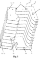
- FIG. 1 an isometric representation of a device 01 according to the invention for determining and / or monitoring the state of a protective cover 10, 12, 13, 14 is shown.
- the device 01 according to the invention has several sensors 21, 25 on a support frame 12, which as a rule comprises several frame elements 13, such as three pressure sensors 21 and a vibration sensor 25.
- FIG. 2 an alternative isometric representation of a device 01 according to the invention for determining and / or monitoring the state of a protective cover 10, 12, 13, 14 is shown.
- this protective cover 10, 12, 13, 14 also has a support frame 12 which comprises a plurality of frame elements 13.
- a temperature and / or humidity sensor 22, 23 and an output unit 50 are located on the end frame 14.
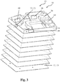
- Fig. 3 a further alternative isometric representation of a device 01 according to the invention for determining and / or monitoring the state of a protective cover 10, 12, 13, 14 is shown.
- the Fig. 3 essentially corresponds to Fig. 2 , with the exception that the end frame 14 is shown in the open state in order to show an insight into the installation space for the various sensor and / or sensor components.
- the end frame 14 has a temperature and / or humidity sensor 22, 23 and an output unit 50 on the outside, as also in FIG Fig. 2 shown.
- an evaluation unit 30, an evaluation unit 40, a wired and / or wireless power supply, such as a rechargeable battery 60, and a transmitting and / or receiving unit 70 for wired and / or wireless data transmission are arranged inside the end frame 14 . Understandably, it is also conceivable that the evaluation and / or evaluation unit 30, 40 can be arranged in a component.
- a support frame 12 is shown which comprises a plurality of frame elements 13.
- FIG. 4 an isometric representation of a device 01 according to the invention for determining and / or monitoring the state of a protective cover 10, 11, 12, 13, 14, 15 is shown, which is used to cover movable machine parts or the like.
- a tool 02 and a table 03 are shown.
- the protective cover 10, 11, 12, 13, 14, 15 comprises a support frame 12, which furthermore comprises a plurality of frame elements 13.
- the protective cover 10, 11, 12, 13, 14, 15 has a length-adjustable protective cover element 11 to protect the machine parts from external influences both in the retracted and in the extended state and also to seal them off from the environment.
- the frame elements 13 are slidably mounted on a guide rail 15.
- the end frame 14 serves as the Fig. 4 can be seen from the Attachment of the protective cover 10, 11, 12, 13, 14, 15 to the machine tool.
- the device 01 according to the invention has a plurality of means 21, 22, 23, 24, 25, 26 for determining and / or monitoring the state of the protective cover 10, 11, 12, 13, 14, 15. So it is Fig. 4 it can be seen that a temperature and / or humidity sensor 22, 23 and an output unit 50 are arranged on the end frame 14. It can also be seen that two pressure sensors 21 and a vibration sensor 25 are arranged on the support frame 12 and / or a frame element 13. It can also be seen that a further means 26, in particular a camera 26, is arranged externally of the device 01 according to the invention.
Landscapes
- Engineering & Computer Science (AREA)
- Mechanical Engineering (AREA)
- General Engineering & Computer Science (AREA)
- Testing Of Devices, Machine Parts, Or Other Structures Thereof (AREA)
- Testing Resistance To Weather, Investigating Materials By Mechanical Methods (AREA)
- Auxiliary Devices For Machine Tools (AREA)
- Machine Tool Sensing Apparatuses (AREA)
Claims (16)
- Procédé pour déterminer et/ou pour surveiller l'état d'un couvercle de protection (10, 11, 12, 13), dans lequel le couvercle de protection (10, 11, 12, 13) comprend au moins un élément de couvercle de protection (11) ajustable en sa longueur, un cadre de support (12), au moins un élément de cadre (13) et/ou un élément de retenue ajustable en sa longueur, le procédé comprenant les étapes suivantesa) obtenir une première valeur d'état d'au moins deux propriétés caractéristiques physiques, mécaniques et/ou chimiques du couvercle de protection (10, 11, 12, 13) à un premier point dans le temps, dans lequel les deux propriétés caractéristiques sont la translucidité, l'absorption de lumière, la réflexion de lumière, la viscosité, l'accélération, la vitesse, l'élasticité, la rigidité, la température, la teneur en humidité, la conductivité électrique, la pression, la charge de compression, la charge de traction, la force de précharge, la porosité, le poids, la fragilité, l'épaisseur et/ou la densité ; etb) obtenir une deuxième valeur d'état desdites au moins deux propriétés caractéristiques du couvercle de protection (10, 11, 12, 13) à un deuxième point dans le temps, qui suit le premier point dans le temps ; etc) comparer les valeurs d'état obtenues ; etd) déterminer l'état du couvercle de protection (10, 11, 12, 13) basé sur la comparaison exécutée dans l'étape c).
- Procédé selon la revendication 1, dans lequel le procédé comprend une étape supplémentaire :e) afficher la détermination exécutée dans l'étape d).
- Procédé selon l'une quelconque des revendications précédentes, dans lequel le procédé comprend une étape supplémentaire b1) suivant l'étape b) :b1) obtenir une troisième valeur d'état desdites au moins deux propriétés caractéristiques du couvercle de protection (10, 11, 12, 13) à un troisième point dans le temps, qui suit le deuxième point dans le temps.
- Procédé selon l'une quelconque des revendications précédentes, dans lequel la première valeur d'état des propriétés caractéristiques respectives est une valeur de référence.
- Procédé selon l'une quelconque des revendications 1 à 4, dans lequel la première, la deuxième et/ou la troisième valeur d'état sont obtenues dans des conditions en principe similaires.
- Procédé selon l'une quelconque des revendications 1 à 4, dans lequel la première, la deuxième et/ou la troisième valeur d'état sont obtenues dans des conditions différentes.
- Procédé selon l'une quelconque des revendications précédentes, dans lequel l'état du couvercle de protection (10, 11, 12, 13) est choisi dans la liste indiquant la vie utile résiduelle, l'état de vieillissement, l'usure, l'existence de dommage et/ou l'imminence d'un intervalle de maintenance.
- Dispositif (01) pour déterminer et/ou pour surveiller l'état d'un couvercle de protection (10, 11, 12, 13), dans lequel le couvercle de protection (10, 11, 12, 13) comprend au moins un élément de couvercle de protection (11) ajustable en sa longueur, un cadre de support (12), au moins un élément de cadre (13) et/ou un élément de retenue ajustable en sa longueur, le dispositif (01) comprenanta) au moins un moyen (21, 22, 23, 24, 25, 26) pour obtenir une première valeur d'état ayant au moins deux propriétés caractéristiques physiques, mécaniques et/ou chimiques du couvercle de protection (10, 11, 12, 13) à un premier point dans le temps, dans lequel le moyen (21, 22, 23, 24, 25, 26) enregistre la translucidité, l'absorption de lumière, la réflexion de lumière, la viscosité, l'accélération, la vitesse, l'élasticité, la rigidité, la température, la teneur en humidité, la conductivité électrique, la pression, la charge de compression, la charge de traction, la force de précharge, la porosité, le poids, la fragilité, l'épaisseur et/ou la densité ; etb) au moins un moyen (21, 22, 23, 24, 25, 26) pour obtenir une deuxième valeur d'état desdites au moins deux propriétés caractéristiques du couvercle de protection (10, 11, 12, 13) à un deuxième point dans le temps, qui suit le premier point dans le temps ; etc) une unité d'évaluation (30) pour comparer les valeurs d'état obtenues ; etd) une unité d'analyse (40) pour déterminer l'état du couvercle de protection (10, 11, 12, 13) basé sur la comparaison exécutée dans l'étape c).
- Dispositif (01) selon la revendication 8, dans lequel le dispositif (01) comprend de pluse) une unité de sortie (50) pour afficher la détermination exécutée dans l'étape d).
- Dispositif (01) selon l'une quelconque des revendications précédentes, dans lequel le dispositif (01) comprend au moins un moyen (21, 22, 23, 24, 25, 26) pour obtenir une troisième valeur d'état desdites au moins deux propriétés caractéristiques du couvercle de protection (10, 11, 12, 13) à un troisième point dans le temps, qui suit le deuxième point dans le temps.
- Dispositif (01) selon l'une quelconque des revendications précédentes, dans lequel la première valeur d'état des propriétés caractéristiques respectives est une valeur de référence.
- Dispositif (01) selon l'une quelconque des revendications 8 à 11, dans lequel le moyen (21, 22, 23, 24, 25, 26), l'unité d'évaluation (30), l'unité d'analyse (40) et/ou l'unité de sortie (50) sont intégrées en partie ou complètement dans le couvercle de protection (10, 11, 12, 13).
- Dispositif (01) selon l'une quelconque des revendications 8 à 11, dans lequel le moyen (21, 22, 23, 24, 25, 26), l'unité d'évaluation (30), l'unité d'analyse (40) et/ou l'unité de sortie (50) sont disposées en dehors du couvercle de protection (10, 11, 12, 13) et sont équipées pour fonctionner sans contact ou en se touchant.
- Dispositif (01) selon l'une quelconque des revendications précédentes, dans lequel le moyen (21, 22, 23, 24, 25, 26) est un compteur, une caméra (26), un compteur de temps de production, un indicateur, un capteur (21, 22, 23, 24, 25) et/ou un système de capteurs.
- Dispositif (01) selon la revendication 14, dans lequel le capteur (21, 22, 23, 24, 25) est un nano-capteur et/ou un microcapteur.
- Dispositif (01) selon l'une quelconque des revendications précédentes, dans lequel l'état du couvercle de protection (10, 11, 12, 13) est choisi dans la liste indiquant la vie utile résiduelle, l'état de vieillissement, l'usure, l'existence de dommage et/ou l'imminence d'un intervalle de maintenance.
Applications Claiming Priority (2)
| Application Number | Priority Date | Filing Date | Title |
|---|---|---|---|
| DE102017101079.3A DE102017101079A1 (de) | 2017-01-20 | 2017-01-20 | Verfahren und Vorrichtung zur Bestimmung und/oder Überwachung des Zustandes einer Schutzabdeckung |
| PCT/EP2018/050933 WO2018134176A1 (fr) | 2017-01-20 | 2018-01-16 | Procédé et dispositif permettant de déterminer et/ou de surveiller l'état d'un capot de protection |
Publications (2)
| Publication Number | Publication Date |
|---|---|
| EP3571008A1 EP3571008A1 (fr) | 2019-11-27 |
| EP3571008B1 true EP3571008B1 (fr) | 2021-12-29 |
Family
ID=61132394
Family Applications (1)
| Application Number | Title | Priority Date | Filing Date |
|---|---|---|---|
| EP18702421.1A Active EP3571008B1 (fr) | 2017-01-20 | 2018-01-16 | Procédé et dispositif permettant de déterminer et/ou de surveiller l'état d'un capot de protection |
Country Status (7)
| Country | Link |
|---|---|
| US (1) | US11298789B2 (fr) |
| EP (1) | EP3571008B1 (fr) |
| JP (1) | JP2020507480A (fr) |
| CN (1) | CN110418695B (fr) |
| DE (1) | DE102017101079A1 (fr) |
| ES (1) | ES2905276T3 (fr) |
| WO (1) | WO2018134176A1 (fr) |
Families Citing this family (2)
| Publication number | Priority date | Publication date | Assignee | Title |
|---|---|---|---|---|
| JP2019521871A (ja) * | 2016-07-15 | 2019-08-08 | アルノ アルノルト ゲーエムベーハー | スナップ留め可能な支持フレームを有する保護カバー |
| JP6746816B1 (ja) * | 2020-03-04 | 2020-08-26 | Dmg森精機株式会社 | 保護装置 |
Citations (3)
| Publication number | Priority date | Publication date | Assignee | Title |
|---|---|---|---|---|
| EP0495259A1 (fr) * | 1990-12-14 | 1992-07-22 | ENIRICERCHE S.p.A. | Dispositif et procédé de contrôle en temps réel des dommages accidentels survenus aux revêtements de protection des structures métalliques ou des pipelines, enterrés ou immergés |
| US20140150533A1 (en) * | 2012-12-03 | 2014-06-05 | Mori Seiki Co., Ltd. | Method and Apparatus for Detecting Airtight State of Machine-Tool Window |
| DE102013008645B3 (de) * | 2013-05-21 | 2014-08-21 | Alsitec S.A.R.L. | Bearbeitungskopf für eine Laserbearbeitungsvorrichtung, Laserbearbeitungsvorrichtung sowie Verfahren zum Messen von Veränderungen der Brennweite einer in einem Bearbeitungskopf enthaltenen Fokussieroptik |
Family Cites Families (20)
| Publication number | Priority date | Publication date | Assignee | Title |
|---|---|---|---|---|
| DE3907419A1 (de) | 1989-03-08 | 1990-09-13 | Ingenieurgesellschaft Fuer Beh | Verfahren zur schadensverhuetung an einer maschine oder vorrichtung |
| JPH09314437A (ja) | 1996-05-27 | 1997-12-09 | Roland D G Kk | 回動式カバーを備えた機器 |
| JP4072231B2 (ja) | 1998-02-09 | 2008-04-09 | 東京精密発条株式会社 | 産業機械用のテレスコピックカバー |
| JP2000052183A (ja) | 1998-08-11 | 2000-02-22 | Okuma Corp | カバー装置の損傷防止装置 |
| DE19905071A1 (de) | 1999-02-08 | 2000-08-10 | Siemens Ag | Meßumformer sowie Verfahren zur Diagnose der Versorgung eines Meßumformers |
| DE10024316B4 (de) | 2000-05-17 | 2004-02-05 | Dirar Najib | Anpassbares Sicherheitsüberwachungsgerät |
| JP2002160140A (ja) | 2000-11-27 | 2002-06-04 | Canon Inc | 加工機械及びそのカバー制御方法 |
| DE102006033607B4 (de) | 2006-07-18 | 2008-09-25 | Arno Arnold Gmbh | Einsteckelement für eine Schutzabdeckung |
| JP5392540B2 (ja) | 2008-12-30 | 2014-01-22 | 豊 嶋田 | 高精度加工工作機械 |
| CN201505837U (zh) | 2009-08-21 | 2010-06-16 | 纽威数控装备(苏州)有限公司 | 一种用于数控机床的导轨防护罩 |
| DE102010011475B4 (de) | 2010-03-16 | 2015-10-29 | Jens Mehnert | Maschinentür und Verfahren zum Betrieb |
| CN102109010A (zh) | 2011-01-24 | 2011-06-29 | 南京工业大学 | 一种可在线监测的转盘轴承 |
| DE102011113388A1 (de) | 2011-09-16 | 2013-03-21 | Arno Arnold Gmbh | Schutzabdeckung |
| JP2014223686A (ja) * | 2013-05-15 | 2014-12-04 | ファナック株式会社 | 保護カバーを有する工作機械 |
| JP2015093367A (ja) | 2013-11-14 | 2015-05-18 | トヨタ自動車株式会社 | 加工室の扉開閉制御方法 |
| JP6247202B2 (ja) * | 2014-12-18 | 2017-12-13 | ファナック株式会社 | 保護カバーの検出装置を備えた工作機械 |
| JP6367782B2 (ja) * | 2015-11-20 | 2018-08-01 | ファナック株式会社 | 工作機械 |
| CN105973586B (zh) | 2016-06-27 | 2018-03-09 | 吉林大学 | 伸缩式导轨防护罩可靠性试验台 |
| CN205719526U (zh) | 2016-06-27 | 2016-11-23 | 吉林大学 | 伸缩式导轨防护罩可靠性试验台 |
| JP6778547B2 (ja) | 2016-08-15 | 2020-11-04 | オークマ株式会社 | テレスコカバー装置 |
-
2017
- 2017-01-20 DE DE102017101079.3A patent/DE102017101079A1/de not_active Ceased
-
2018
- 2018-01-16 ES ES18702421T patent/ES2905276T3/es active Active
- 2018-01-16 US US16/477,059 patent/US11298789B2/en active Active
- 2018-01-16 WO PCT/EP2018/050933 patent/WO2018134176A1/fr not_active Ceased
- 2018-01-16 CN CN201880017638.2A patent/CN110418695B/zh not_active Expired - Fee Related
- 2018-01-16 JP JP2019538610A patent/JP2020507480A/ja active Pending
- 2018-01-16 EP EP18702421.1A patent/EP3571008B1/fr active Active
Patent Citations (3)
| Publication number | Priority date | Publication date | Assignee | Title |
|---|---|---|---|---|
| EP0495259A1 (fr) * | 1990-12-14 | 1992-07-22 | ENIRICERCHE S.p.A. | Dispositif et procédé de contrôle en temps réel des dommages accidentels survenus aux revêtements de protection des structures métalliques ou des pipelines, enterrés ou immergés |
| US20140150533A1 (en) * | 2012-12-03 | 2014-06-05 | Mori Seiki Co., Ltd. | Method and Apparatus for Detecting Airtight State of Machine-Tool Window |
| DE102013008645B3 (de) * | 2013-05-21 | 2014-08-21 | Alsitec S.A.R.L. | Bearbeitungskopf für eine Laserbearbeitungsvorrichtung, Laserbearbeitungsvorrichtung sowie Verfahren zum Messen von Veränderungen der Brennweite einer in einem Bearbeitungskopf enthaltenen Fokussieroptik |
Also Published As
| Publication number | Publication date |
|---|---|
| US20190337108A1 (en) | 2019-11-07 |
| WO2018134176A1 (fr) | 2018-07-26 |
| EP3571008A1 (fr) | 2019-11-27 |
| JP2020507480A (ja) | 2020-03-12 |
| DE102017101079A1 (de) | 2018-07-26 |
| US11298789B2 (en) | 2022-04-12 |
| ES2905276T3 (es) | 2022-04-07 |
| CN110418695B (zh) | 2022-02-08 |
| CN110418695A (zh) | 2019-11-05 |
Similar Documents
| Publication | Publication Date | Title |
|---|---|---|
| DE112012005650B4 (de) | Risikomesssystem | |
| DE102007038344B4 (de) | Integriertes Überwachungsverfahren für Nukleareinrichtungen und ein solches Verfahren verwendende Einrichtung | |
| EP3513155B1 (fr) | Procédé et dispositif pour déterminer et/ou surveiller l'état d'une huile de transformateur | |
| DE112005002077B4 (de) | Zustandserfassungsvorrichtung, Zustandserfassungsverfahren, Zustandserfassungsprogramm, Informationsaufzeichnungsmedium dafür sowie Zustandsanzeigevorrichtung, Zustandsanzeigeverfahren, Zustandsanzeigeprogramm und Informationsaufzeichnungsmedium dafür | |
| DE102010015325B4 (de) | Prüfeinrichtung für ein Nietsetzwerkzeug | |
| DE2622120A1 (de) | Verfahren und vorrichtung zur automatischen ueberwachung von anlagen | |
| EP2730906A2 (fr) | Dispositif et procédé de surveillance de l'état d'un palier à roulement | |
| EP0612643A1 (fr) | Dispositif de surveillance d'un élément de sécurité dans un véhicule automobile | |
| EP3757336B1 (fr) | Procédé de détermination de la tension d'une courroie d'entraînement | |
| AT517886B1 (de) | Vorrichtung zum Überprüfen eines Zustandes eines Maschinenteils | |
| DE112015005528T5 (de) | Kontrollgerät und Verfahren zur Bestimmung der Betriebsbereitschaft einer mit einem Druckmedium betriebenen Vorrichtung | |
| DE102022002464A1 (de) | Verfahren und Vorrichtung zur Bestimmung der Restlebensdauer eines Getriebes | |
| EP2956348B1 (fr) | Surveillance d'éléments d'attelage d'un véhicule | |
| EP3571008A1 (fr) | Procédé et dispositif permettant de déterminer et/ou de surveiller l'état d'un capot de protection | |
| DE102017106919A1 (de) | Verfahren zur Bestimmung einer Schädigungsmaßunsicherheit eines Kraftfahrzeugs | |
| DE102013205353B4 (de) | Verfahren zum Warten einer Maschine der Tabak verarbeitenden Industrie, und entsprechend eingerichtete Maschine | |
| DE102019107242A1 (de) | Diagnoseverfahren, Diagnosesystem und Kraftfahrzeug | |
| EP3771594B1 (fr) | Procédé de détection des événements de mesure défectueux et produit programme informatique | |
| DE102023200789A1 (de) | Bearbeitungsgenauigkeits-Diagnosevorrichtung und Bearbeitungsgenauigkeits-Managementsystem für Werkzeugmaschinen | |
| DE102017113720A1 (de) | Verfahren zum Schmieren einer Linearführung | |
| DE102016009256A1 (de) | Prüfverfahren | |
| EP3554768A1 (fr) | Poste de sécurité, laboratoire mobile et procédé | |
| DE102010011475B4 (de) | Maschinentür und Verfahren zum Betrieb | |
| DE102016201089A1 (de) | Verfahren zur Erkennung von Beschädigungen an einer stationären elektrischen Einrichtung und stationäre elektrische Einrichtung mit einem Sensor | |
| DE102016115979B4 (de) | Verfahren und Anordnung zur Sicherung von zuverlässigen Angaben über Messunsicherheiten von Messsystemen bei veränderlichen Umgebungsbedingungen |
Legal Events
| Date | Code | Title | Description |
|---|---|---|---|
| STAA | Information on the status of an ep patent application or granted ep patent |
Free format text: STATUS: UNKNOWN |
|
| STAA | Information on the status of an ep patent application or granted ep patent |
Free format text: STATUS: THE INTERNATIONAL PUBLICATION HAS BEEN MADE |
|
| PUAI | Public reference made under article 153(3) epc to a published international application that has entered the european phase |
Free format text: ORIGINAL CODE: 0009012 |
|
| STAA | Information on the status of an ep patent application or granted ep patent |
Free format text: STATUS: REQUEST FOR EXAMINATION WAS MADE |
|
| 17P | Request for examination filed |
Effective date: 20190719 |
|
| AK | Designated contracting states |
Kind code of ref document: A1 Designated state(s): AL AT BE BG CH CY CZ DE DK EE ES FI FR GB GR HR HU IE IS IT LI LT LU LV MC MK MT NL NO PL PT RO RS SE SI SK SM TR |
|
| AX | Request for extension of the european patent |
Extension state: BA ME |
|
| DAV | Request for validation of the european patent (deleted) | ||
| DAX | Request for extension of the european patent (deleted) | ||
| STAA | Information on the status of an ep patent application or granted ep patent |
Free format text: STATUS: EXAMINATION IS IN PROGRESS |
|
| 17Q | First examination report despatched |
Effective date: 20200622 |
|
| GRAP | Despatch of communication of intention to grant a patent |
Free format text: ORIGINAL CODE: EPIDOSNIGR1 |
|
| STAA | Information on the status of an ep patent application or granted ep patent |
Free format text: STATUS: GRANT OF PATENT IS INTENDED |
|
| GRAJ | Information related to disapproval of communication of intention to grant by the applicant or resumption of examination proceedings by the epo deleted |
Free format text: ORIGINAL CODE: EPIDOSDIGR1 |
|
| STAA | Information on the status of an ep patent application or granted ep patent |
Free format text: STATUS: EXAMINATION IS IN PROGRESS |
|
| INTG | Intention to grant announced |
Effective date: 20210520 |
|
| INTC | Intention to grant announced (deleted) | ||
| GRAP | Despatch of communication of intention to grant a patent |
Free format text: ORIGINAL CODE: EPIDOSNIGR1 |
|
| STAA | Information on the status of an ep patent application or granted ep patent |
Free format text: STATUS: GRANT OF PATENT IS INTENDED |
|
| INTG | Intention to grant announced |
Effective date: 20210716 |
|
| GRAS | Grant fee paid |
Free format text: ORIGINAL CODE: EPIDOSNIGR3 |
|
| GRAA | (expected) grant |
Free format text: ORIGINAL CODE: 0009210 |
|
| STAA | Information on the status of an ep patent application or granted ep patent |
Free format text: STATUS: THE PATENT HAS BEEN GRANTED |
|
| AK | Designated contracting states |
Kind code of ref document: B1 Designated state(s): AL AT BE BG CH CY CZ DE DK EE ES FI FR GB GR HR HU IE IS IT LI LT LU LV MC MK MT NL NO PL PT RO RS SE SI SK SM TR |
|
| REG | Reference to a national code |
Ref country code: GB Ref legal event code: FG4D Free format text: NOT ENGLISH |
|
| REG | Reference to a national code |
Ref country code: CH Ref legal event code: EP |
|
| REG | Reference to a national code |
Ref country code: AT Ref legal event code: REF Ref document number: 1458332 Country of ref document: AT Kind code of ref document: T Effective date: 20220115 |
|
| REG | Reference to a national code |
Ref country code: IE Ref legal event code: FG4D Free format text: LANGUAGE OF EP DOCUMENT: GERMAN |
|
| REG | Reference to a national code |
Ref country code: DE Ref legal event code: R096 Ref document number: 502018008322 Country of ref document: DE |
|
| REG | Reference to a national code |
Ref country code: ES Ref legal event code: FG2A Ref document number: 2905276 Country of ref document: ES Kind code of ref document: T3 Effective date: 20220407 |
|
| REG | Reference to a national code |
Ref country code: LT Ref legal event code: MG9D |
|
| PG25 | Lapsed in a contracting state [announced via postgrant information from national office to epo] |
Ref country code: RS Free format text: LAPSE BECAUSE OF FAILURE TO SUBMIT A TRANSLATION OF THE DESCRIPTION OR TO PAY THE FEE WITHIN THE PRESCRIBED TIME-LIMIT Effective date: 20211229 Ref country code: LT Free format text: LAPSE BECAUSE OF FAILURE TO SUBMIT A TRANSLATION OF THE DESCRIPTION OR TO PAY THE FEE WITHIN THE PRESCRIBED TIME-LIMIT Effective date: 20211229 Ref country code: FI Free format text: LAPSE BECAUSE OF FAILURE TO SUBMIT A TRANSLATION OF THE DESCRIPTION OR TO PAY THE FEE WITHIN THE PRESCRIBED TIME-LIMIT Effective date: 20211229 Ref country code: BG Free format text: LAPSE BECAUSE OF FAILURE TO SUBMIT A TRANSLATION OF THE DESCRIPTION OR TO PAY THE FEE WITHIN THE PRESCRIBED TIME-LIMIT Effective date: 20220329 |
|
| REG | Reference to a national code |
Ref country code: NL Ref legal event code: MP Effective date: 20211229 |
|
| PG25 | Lapsed in a contracting state [announced via postgrant information from national office to epo] |
Ref country code: SE Free format text: LAPSE BECAUSE OF FAILURE TO SUBMIT A TRANSLATION OF THE DESCRIPTION OR TO PAY THE FEE WITHIN THE PRESCRIBED TIME-LIMIT Effective date: 20211229 Ref country code: NO Free format text: LAPSE BECAUSE OF FAILURE TO SUBMIT A TRANSLATION OF THE DESCRIPTION OR TO PAY THE FEE WITHIN THE PRESCRIBED TIME-LIMIT Effective date: 20220329 Ref country code: LV Free format text: LAPSE BECAUSE OF FAILURE TO SUBMIT A TRANSLATION OF THE DESCRIPTION OR TO PAY THE FEE WITHIN THE PRESCRIBED TIME-LIMIT Effective date: 20211229 Ref country code: HR Free format text: LAPSE BECAUSE OF FAILURE TO SUBMIT A TRANSLATION OF THE DESCRIPTION OR TO PAY THE FEE WITHIN THE PRESCRIBED TIME-LIMIT Effective date: 20211229 Ref country code: GR Free format text: LAPSE BECAUSE OF FAILURE TO SUBMIT A TRANSLATION OF THE DESCRIPTION OR TO PAY THE FEE WITHIN THE PRESCRIBED TIME-LIMIT Effective date: 20220330 |
|
| PG25 | Lapsed in a contracting state [announced via postgrant information from national office to epo] |
Ref country code: NL Free format text: LAPSE BECAUSE OF FAILURE TO SUBMIT A TRANSLATION OF THE DESCRIPTION OR TO PAY THE FEE WITHIN THE PRESCRIBED TIME-LIMIT Effective date: 20211229 |
|
| PG25 | Lapsed in a contracting state [announced via postgrant information from national office to epo] |
Ref country code: SM Free format text: LAPSE BECAUSE OF FAILURE TO SUBMIT A TRANSLATION OF THE DESCRIPTION OR TO PAY THE FEE WITHIN THE PRESCRIBED TIME-LIMIT Effective date: 20211229 Ref country code: SK Free format text: LAPSE BECAUSE OF FAILURE TO SUBMIT A TRANSLATION OF THE DESCRIPTION OR TO PAY THE FEE WITHIN THE PRESCRIBED TIME-LIMIT Effective date: 20211229 Ref country code: RO Free format text: LAPSE BECAUSE OF FAILURE TO SUBMIT A TRANSLATION OF THE DESCRIPTION OR TO PAY THE FEE WITHIN THE PRESCRIBED TIME-LIMIT Effective date: 20211229 Ref country code: PT Free format text: LAPSE BECAUSE OF FAILURE TO SUBMIT A TRANSLATION OF THE DESCRIPTION OR TO PAY THE FEE WITHIN THE PRESCRIBED TIME-LIMIT Effective date: 20220429 Ref country code: EE Free format text: LAPSE BECAUSE OF FAILURE TO SUBMIT A TRANSLATION OF THE DESCRIPTION OR TO PAY THE FEE WITHIN THE PRESCRIBED TIME-LIMIT Effective date: 20211229 Ref country code: CZ Free format text: LAPSE BECAUSE OF FAILURE TO SUBMIT A TRANSLATION OF THE DESCRIPTION OR TO PAY THE FEE WITHIN THE PRESCRIBED TIME-LIMIT Effective date: 20211229 |
|
| PG25 | Lapsed in a contracting state [announced via postgrant information from national office to epo] |
Ref country code: PL Free format text: LAPSE BECAUSE OF FAILURE TO SUBMIT A TRANSLATION OF THE DESCRIPTION OR TO PAY THE FEE WITHIN THE PRESCRIBED TIME-LIMIT Effective date: 20211229 |
|
| PG25 | Lapsed in a contracting state [announced via postgrant information from national office to epo] |
Ref country code: MC Free format text: LAPSE BECAUSE OF FAILURE TO SUBMIT A TRANSLATION OF THE DESCRIPTION OR TO PAY THE FEE WITHIN THE PRESCRIBED TIME-LIMIT Effective date: 20211229 Ref country code: IS Free format text: LAPSE BECAUSE OF FAILURE TO SUBMIT A TRANSLATION OF THE DESCRIPTION OR TO PAY THE FEE WITHIN THE PRESCRIBED TIME-LIMIT Effective date: 20220429 |
|
| REG | Reference to a national code |
Ref country code: DE Ref legal event code: R097 Ref document number: 502018008322 Country of ref document: DE |
|
| REG | Reference to a national code |
Ref country code: BE Ref legal event code: MM Effective date: 20220131 |
|
| PG25 | Lapsed in a contracting state [announced via postgrant information from national office to epo] |
Ref country code: LU Free format text: LAPSE BECAUSE OF NON-PAYMENT OF DUE FEES Effective date: 20220116 Ref country code: DK Free format text: LAPSE BECAUSE OF FAILURE TO SUBMIT A TRANSLATION OF THE DESCRIPTION OR TO PAY THE FEE WITHIN THE PRESCRIBED TIME-LIMIT Effective date: 20211229 Ref country code: AL Free format text: LAPSE BECAUSE OF FAILURE TO SUBMIT A TRANSLATION OF THE DESCRIPTION OR TO PAY THE FEE WITHIN THE PRESCRIBED TIME-LIMIT Effective date: 20211229 |
|
| PLBE | No opposition filed within time limit |
Free format text: ORIGINAL CODE: 0009261 |
|
| STAA | Information on the status of an ep patent application or granted ep patent |
Free format text: STATUS: NO OPPOSITION FILED WITHIN TIME LIMIT |
|
| GBPC | Gb: european patent ceased through non-payment of renewal fee |
Effective date: 20220329 |
|
| PG25 | Lapsed in a contracting state [announced via postgrant information from national office to epo] |
Ref country code: BE Free format text: LAPSE BECAUSE OF NON-PAYMENT OF DUE FEES Effective date: 20220131 |
|
| 26N | No opposition filed |
Effective date: 20220930 |
|
| PG25 | Lapsed in a contracting state [announced via postgrant information from national office to epo] |
Ref country code: IT Free format text: LAPSE BECAUSE OF NON-PAYMENT OF DUE FEES Effective date: 20220116 Ref country code: IE Free format text: LAPSE BECAUSE OF NON-PAYMENT OF DUE FEES Effective date: 20220116 Ref country code: GB Free format text: LAPSE BECAUSE OF NON-PAYMENT OF DUE FEES Effective date: 20220329 |
|
| PG25 | Lapsed in a contracting state [announced via postgrant information from national office to epo] |
Ref country code: SI Free format text: LAPSE BECAUSE OF FAILURE TO SUBMIT A TRANSLATION OF THE DESCRIPTION OR TO PAY THE FEE WITHIN THE PRESCRIBED TIME-LIMIT Effective date: 20211229 |
|
| PGFP | Annual fee paid to national office [announced via postgrant information from national office to epo] |
Ref country code: ES Payment date: 20230216 Year of fee payment: 6 Ref country code: CH Payment date: 20230130 Year of fee payment: 6 Ref country code: AT Payment date: 20230118 Year of fee payment: 6 Ref country code: FR Payment date: 20230123 Year of fee payment: 6 |
|
| P01 | Opt-out of the competence of the unified patent court (upc) registered |
Effective date: 20230517 |
|
| PG25 | Lapsed in a contracting state [announced via postgrant information from national office to epo] |
Ref country code: MK Free format text: LAPSE BECAUSE OF FAILURE TO SUBMIT A TRANSLATION OF THE DESCRIPTION OR TO PAY THE FEE WITHIN THE PRESCRIBED TIME-LIMIT Effective date: 20211229 Ref country code: CY Free format text: LAPSE BECAUSE OF FAILURE TO SUBMIT A TRANSLATION OF THE DESCRIPTION OR TO PAY THE FEE WITHIN THE PRESCRIBED TIME-LIMIT Effective date: 20211229 |
|
| PG25 | Lapsed in a contracting state [announced via postgrant information from national office to epo] |
Ref country code: HU Free format text: LAPSE BECAUSE OF FAILURE TO SUBMIT A TRANSLATION OF THE DESCRIPTION OR TO PAY THE FEE WITHIN THE PRESCRIBED TIME-LIMIT; INVALID AB INITIO Effective date: 20180116 |
|
| REG | Reference to a national code |
Ref country code: CH Ref legal event code: PL |
|
| REG | Reference to a national code |
Ref country code: AT Ref legal event code: MM01 Ref document number: 1458332 Country of ref document: AT Kind code of ref document: T Effective date: 20240116 |
|
| PG25 | Lapsed in a contracting state [announced via postgrant information from national office to epo] |
Ref country code: MT Free format text: LAPSE BECAUSE OF FAILURE TO SUBMIT A TRANSLATION OF THE DESCRIPTION OR TO PAY THE FEE WITHIN THE PRESCRIBED TIME-LIMIT Effective date: 20211229 |
|
| PG25 | Lapsed in a contracting state [announced via postgrant information from national office to epo] |
Ref country code: FR Free format text: LAPSE BECAUSE OF NON-PAYMENT OF DUE FEES Effective date: 20240131 |
|
| PG25 | Lapsed in a contracting state [announced via postgrant information from national office to epo] |
Ref country code: CH Free format text: LAPSE BECAUSE OF NON-PAYMENT OF DUE FEES Effective date: 20240131 |
|
| PG25 | Lapsed in a contracting state [announced via postgrant information from national office to epo] |
Ref country code: AT Free format text: LAPSE BECAUSE OF NON-PAYMENT OF DUE FEES Effective date: 20240116 |
|
| PG25 | Lapsed in a contracting state [announced via postgrant information from national office to epo] |
Ref country code: FR Free format text: LAPSE BECAUSE OF NON-PAYMENT OF DUE FEES Effective date: 20240131 Ref country code: CH Free format text: LAPSE BECAUSE OF NON-PAYMENT OF DUE FEES Effective date: 20240131 Ref country code: AT Free format text: LAPSE BECAUSE OF NON-PAYMENT OF DUE FEES Effective date: 20240116 |
|
| REG | Reference to a national code |
Ref country code: ES Ref legal event code: FD2A Effective date: 20250228 |
|
| PG25 | Lapsed in a contracting state [announced via postgrant information from national office to epo] |
Ref country code: ES Free format text: LAPSE BECAUSE OF NON-PAYMENT OF DUE FEES Effective date: 20240117 |
|
| PG25 | Lapsed in a contracting state [announced via postgrant information from national office to epo] |
Ref country code: TR Free format text: LAPSE BECAUSE OF FAILURE TO SUBMIT A TRANSLATION OF THE DESCRIPTION OR TO PAY THE FEE WITHIN THE PRESCRIBED TIME-LIMIT Effective date: 20211229 |
|
| PGFP | Annual fee paid to national office [announced via postgrant information from national office to epo] |
Ref country code: DE Payment date: 20260318 Year of fee payment: 9 |