EP3572560B1 - Einkristallherstellungsvorrichtung - Google Patents
Einkristallherstellungsvorrichtung Download PDFInfo
- Publication number
- EP3572560B1 EP3572560B1 EP18785795.8A EP18785795A EP3572560B1 EP 3572560 B1 EP3572560 B1 EP 3572560B1 EP 18785795 A EP18785795 A EP 18785795A EP 3572560 B1 EP3572560 B1 EP 3572560B1
- Authority
- EP
- European Patent Office
- Prior art keywords
- raw material
- granular raw
- crystal
- melt
- crystal production
- Prior art date
- Legal status (The legal status is an assumption and is not a legal conclusion. Google has not performed a legal analysis and makes no representation as to the accuracy of the status listed.)
- Active
Links
Images


Classifications
-
- C—CHEMISTRY; METALLURGY
- C30—CRYSTAL GROWTH
- C30B—SINGLE-CRYSTAL GROWTH; UNIDIRECTIONAL SOLIDIFICATION OF EUTECTIC MATERIAL OR UNIDIRECTIONAL DEMIXING OF EUTECTOID MATERIAL; REFINING BY ZONE-MELTING OF MATERIAL; PRODUCTION OF A HOMOGENEOUS POLYCRYSTALLINE MATERIAL WITH DEFINED STRUCTURE; SINGLE CRYSTALS OR HOMOGENEOUS POLYCRYSTALLINE MATERIAL WITH DEFINED STRUCTURE; AFTER-TREATMENT OF SINGLE CRYSTALS OR A HOMOGENEOUS POLYCRYSTALLINE MATERIAL WITH DEFINED STRUCTURE; APPARATUS THEREFOR
- C30B11/00—Single-crystal growth by normal freezing or freezing under temperature gradient, e.g. Bridgman-Stockbarger method
- C30B11/003—Heating or cooling of the melt or the crystallised material
-
- C—CHEMISTRY; METALLURGY
- C30—CRYSTAL GROWTH
- C30B—SINGLE-CRYSTAL GROWTH; UNIDIRECTIONAL SOLIDIFICATION OF EUTECTIC MATERIAL OR UNIDIRECTIONAL DEMIXING OF EUTECTOID MATERIAL; REFINING BY ZONE-MELTING OF MATERIAL; PRODUCTION OF A HOMOGENEOUS POLYCRYSTALLINE MATERIAL WITH DEFINED STRUCTURE; SINGLE CRYSTALS OR HOMOGENEOUS POLYCRYSTALLINE MATERIAL WITH DEFINED STRUCTURE; AFTER-TREATMENT OF SINGLE CRYSTALS OR A HOMOGENEOUS POLYCRYSTALLINE MATERIAL WITH DEFINED STRUCTURE; APPARATUS THEREFOR
- C30B13/00—Single-crystal growth by zone-melting; Refining by zone-melting
- C30B13/08—Single-crystal growth by zone-melting; Refining by zone-melting adding crystallising materials or reactants forming it in situ to the molten zone
-
- C—CHEMISTRY; METALLURGY
- C30—CRYSTAL GROWTH
- C30B—SINGLE-CRYSTAL GROWTH; UNIDIRECTIONAL SOLIDIFICATION OF EUTECTIC MATERIAL OR UNIDIRECTIONAL DEMIXING OF EUTECTOID MATERIAL; REFINING BY ZONE-MELTING OF MATERIAL; PRODUCTION OF A HOMOGENEOUS POLYCRYSTALLINE MATERIAL WITH DEFINED STRUCTURE; SINGLE CRYSTALS OR HOMOGENEOUS POLYCRYSTALLINE MATERIAL WITH DEFINED STRUCTURE; AFTER-TREATMENT OF SINGLE CRYSTALS OR A HOMOGENEOUS POLYCRYSTALLINE MATERIAL WITH DEFINED STRUCTURE; APPARATUS THEREFOR
- C30B11/00—Single-crystal growth by normal freezing or freezing under temperature gradient, e.g. Bridgman-Stockbarger method
- C30B11/04—Single-crystal growth by normal freezing or freezing under temperature gradient, e.g. Bridgman-Stockbarger method adding crystallising materials or reactants forming it in situ to the melt
- C30B11/08—Single-crystal growth by normal freezing or freezing under temperature gradient, e.g. Bridgman-Stockbarger method adding crystallising materials or reactants forming it in situ to the melt every component of the crystal composition being added during the crystallisation
-
- C—CHEMISTRY; METALLURGY
- C30—CRYSTAL GROWTH
- C30B—SINGLE-CRYSTAL GROWTH; UNIDIRECTIONAL SOLIDIFICATION OF EUTECTIC MATERIAL OR UNIDIRECTIONAL DEMIXING OF EUTECTOID MATERIAL; REFINING BY ZONE-MELTING OF MATERIAL; PRODUCTION OF A HOMOGENEOUS POLYCRYSTALLINE MATERIAL WITH DEFINED STRUCTURE; SINGLE CRYSTALS OR HOMOGENEOUS POLYCRYSTALLINE MATERIAL WITH DEFINED STRUCTURE; AFTER-TREATMENT OF SINGLE CRYSTALS OR A HOMOGENEOUS POLYCRYSTALLINE MATERIAL WITH DEFINED STRUCTURE; APPARATUS THEREFOR
- C30B13/00—Single-crystal growth by zone-melting; Refining by zone-melting
- C30B13/14—Crucibles or vessels
-
- C—CHEMISTRY; METALLURGY
- C30—CRYSTAL GROWTH
- C30B—SINGLE-CRYSTAL GROWTH; UNIDIRECTIONAL SOLIDIFICATION OF EUTECTIC MATERIAL OR UNIDIRECTIONAL DEMIXING OF EUTECTOID MATERIAL; REFINING BY ZONE-MELTING OF MATERIAL; PRODUCTION OF A HOMOGENEOUS POLYCRYSTALLINE MATERIAL WITH DEFINED STRUCTURE; SINGLE CRYSTALS OR HOMOGENEOUS POLYCRYSTALLINE MATERIAL WITH DEFINED STRUCTURE; AFTER-TREATMENT OF SINGLE CRYSTALS OR A HOMOGENEOUS POLYCRYSTALLINE MATERIAL WITH DEFINED STRUCTURE; APPARATUS THEREFOR
- C30B13/00—Single-crystal growth by zone-melting; Refining by zone-melting
- C30B13/16—Heating of the molten zone
- C30B13/22—Heating of the molten zone by irradiation or electric discharge
- C30B13/24—Heating of the molten zone by irradiation or electric discharge using electromagnetic waves
-
- C—CHEMISTRY; METALLURGY
- C30—CRYSTAL GROWTH
- C30B—SINGLE-CRYSTAL GROWTH; UNIDIRECTIONAL SOLIDIFICATION OF EUTECTIC MATERIAL OR UNIDIRECTIONAL DEMIXING OF EUTECTOID MATERIAL; REFINING BY ZONE-MELTING OF MATERIAL; PRODUCTION OF A HOMOGENEOUS POLYCRYSTALLINE MATERIAL WITH DEFINED STRUCTURE; SINGLE CRYSTALS OR HOMOGENEOUS POLYCRYSTALLINE MATERIAL WITH DEFINED STRUCTURE; AFTER-TREATMENT OF SINGLE CRYSTALS OR A HOMOGENEOUS POLYCRYSTALLINE MATERIAL WITH DEFINED STRUCTURE; APPARATUS THEREFOR
- C30B13/00—Single-crystal growth by zone-melting; Refining by zone-melting
- C30B13/28—Controlling or regulating
Definitions
- the present invention relates to: a single-crystal production equipment which highly efficiently produces a large single crystal of, for example, 1, 000 to 2, 000 mm in diameter while homogenizing its composition to be optimum.
- the power generation cost using a solar cell have been largely reduced than before, it is still considered rather high as compared to the power generation cost of, for example, a thermal power plant using fossil energy, a hydraulic power plant or a nuclear power plant, and a further cost reduction is demanded.
- a single-crystal silicon substrate having a single orientation as a whole hereinafter, also referred to as single-crystal substrate" or a polycrystalline silicon substrate containing a large number of grain boundaries (hereinafter, also referred to as "polycrystal substrate”) is used. Since the grain boundaries contained in a polycrystal substrate are believed to deteriorate the solar cell properties, a single-crystal substrate is more convenient for high-efficiency power generation.
- the cost of a conventional single-crystal substrate production method is rather expensive than the production cost of a polycrystal substrate; therefore, it has been desired to develop a novel production method by which a high-performance single-crystal substrate can be produced inexpensively.
- the single-crystal substrate may be of boron-doped P-type or phosphorus-doped N-type; however, there are growing expectations for phosphorus-doped N-type single-crystal substrates since they make high-efficient power generation possible.
- HIT type in which amorphous silicon that can be used in a relatively short wavelength region and a phosphorus-doped N-type single-crystal substrate that can be used in a relatively long wavelength region are used in combination, is regarded as a system capable of achieving high conversion efficiency.
- an N-type silicon single-crystal substrate is required in the same manner as in the HIT-type system.
- a method belonging to so-called “melt method” in which a melt formed by melting a raw material is solidified to produce a single crystal, can most quickly produce a large crystal.
- a “melt method” for example, a casting method in which a melt is poured into a mold and then solidified, a unidirectional solidification method in which a melt in a crucible is solidified from a lower part to an upper part, a pulling method in which a seed single crystal is immersed into a melt in a crucible and then pulled upward while being allowed to grow, and a floating-zone melting method in which a melt is formed by local heating of a rod-shaped raw material, and melting and solidification of the raw material are continuously performed, are known.
- the floating-zone melting method which does not use a crucible and thus has advantages in that it can yield a high-purity product without any contamination from a crucible and that the resulting product has a uniform dopant concentration because of continuous melting and solidification of a raw material, has been mainly used for research and development.
- quartz that can stably retain a melt and is conveniently inexpensive is used since, in the case of producing a silicon single crystal, a silicon melt is highly reactive and no other appropriate material can be found.
- quartz requires careful attention since quartz reacts with a silicon melt to generate silicon monoxide (SiO) that is partially solid-dissolved in the resulting product.
- the Bridgman method As a method of producing a large single crystal by forming a raw material melt in a crucible, the Bridgman method is known. This is a method in which a seed single crystal is placed on the bottom of a crucible, and a raw material melt thereabove is solidified on the seed single crystal to produce a single crystal as a whole.
- the product is an aggregate of numerous small crystals, which is referred to as "polycrystalline silicon".
- Such a polycrystalline silicon aggregate produced by a casting method is cut in the horizontal direction and used as a substrate and, in an upper part and a lower part of the crucible, the boundaries between single-crystal particles exist along the vertical direction of the substrate. Meanwhile, in the vicinity of the center of the crucible, the boundaries between single-crystal particles exist along the parallel direction of the substrate.
- the unidirectional solidification method made it possible to produce a crystal having an improved efficiency as a solar cell; however, in this method, since the reaction time of a carbon crucible and a silicon melt is incomparably longer, a silicon carbide phase generated by the reaction is far thicker than in a casting method.
- Silicon carbide is rigid and thus causes various troubles in the substrate production process such as cutting; therefore, it was difficult to improve the product yield.
- quartz crucible made of quartz
- silicon nitride material as a release agent to prevent quartz and silicon from fusing together and to thereby inhibit cracking of the resulting solidified product
- the Bridgman method As a method of crystallizing the whole product as a single crystal by a unidirectional solidification method, the Bridgman method is known as described above. When silicon is used, however, it has been considered difficult to apply the Bridgman method since the use of a release agent for inhibition of fusion between a quartz crucible and a silicon melt causes silicon microcrystals to start growing from the parts coated with the release agent, so that a single crystal is not formed as a whole.
- a rotary pulling method pulseling method
- high-frequency floating-zone melting method high-frequency FZ method
- infrared floating-zone melting method infrared FZ method
- a silicon raw material is melted in a quartz crucible, a thin seed single crystal is immersed therein, and a single crystal is allowed to grow continuously while the single crystal is gradually fattened and pulled up, whereby a large single crystal is obtained.
- a round rod-shaped raw material rod and a seed single crystal arranged below the raw material rod are prepared, a lower part of the round rod-shaped raw material rod is heat-melted by high-frequency induction, the resulting melt is joined with the seed single crystal below, and the whole resultant is lowered so as to continuously perform melting of the raw material rod on the upper side of the melt and solidification of a single crystal from the melt on the lower side, whereby a single crystal is produced.
- This high-frequency FZ method does not use a quartz crucible and is thus capable of producing a high-purity single crystal having no contamination with a quartz component.
- the maximum diameter of a single crystal that can be produced is small and a specially-prepared highly dense and expensive raw material rod is required; therefore, the high-frequency FZ method is not employed for the production of a silicon single crystal for common solar cells.
- a round rod-shaped raw material is locally heated by irradiation with an infrared ray to form a melt, and melting of the raw material on the upper side of the melt and precipitation of a solid as a single crystal on the lower side are continuously performed, whereby a single crystal is produced.
- the infrared FZ method can be applied to a wide variety of materials of raw material rods ranging from insulators to good conductors; however, since the maximum diameter of a product that can be produced is small, the infrared FZ method is not employed for industrial purposes that require a large single crystal.
- a substrate doped with boron or phosphorus as a dopant is used for utilization of crystalline silicon as a solar cell.
- An excessively low dopant concentration leads to a reduction in the conversion efficiency, while an excessively high dopant concentration also deteriorates the conversion efficiency due to recombination; therefore, there is an optimum concentration for both boron and phosphorus, and it is needless to say that a product that is uniform and has such an optimum-concentration composition throughout the crystal is desired.
- the above-described pulling method belongs to so-called unidirectional solidification method where a melt is entirely solidified from an upper part in the downward direction; therefore, it is known to have a characteristic feature that the concentration of a dopant such as boron and phosphorus in the resulting product is not constant due to a segregation phenomenon.
- a melt and a solidified crystal do not have the same dopant concentration, and solidification proceeds at a ratio defined by the substance.
- This ratio is referred to as "distribution coefficient" and, taking the concentration in the melt as 1, the concentration in the resulting crystal is approximately 0.8 for boron and approximately 0.35 for phosphorus.
- the dopant concentration in the generated crystal is lower than that in the melt, and the difference remains in the melt, so that the dopant concentration in the melt gradually increases as the single crystal grows.
- the ratio between the dopant concentration in the melt and the dopant concentration in the generated crystal is defined by a distribution coefficient, when the dopant concentration in the melt increases as crystallization proceeds, the dopant concentration in the crystal being generated also gradually increases.
- an optimum-composition solid is solidified only from a solution having a composition coexisting at an equilibrium (this solution is referred to as "solvent"); however, since the solidification causes a change in the composition of the solution, it is necessary to maintain the composition and amount of the solvent constant at all times by supplying thereto a raw material having the same composition and amount as the solvent being solidified.
- the solvent for example, when silicon is doped with phosphorus, since the distribution coefficient is approximately 0.35, the solvent has a concentration of approximately three times higher than that of a crystal having an optimum-concentration composition.
- quartz is the only crucible material that can be applied; however, since quartz fuses with silicon to cause cracking in the resulting product, the quartz surface has to be coated with a release agent.
- the resulting product is entirely a large single crystal, excluding those parts in the vicinity of the inner wall of the crucible.
- the development a method in which a traveling solvent method is applied by controlling the amount of a raw material being supplied to be the same as the amount of a solid being precipitated while maintaining the scheme of large single-crystal production by the Bridgman method where the growth of new microcrystals from the inner wall of a crucible coated with a release agent should make it possible to produce a large single crystal having a uniform dopant concentration with an optimum composition.
- Patent Literature 2 describes a single-crystal production equipment which produces a single crystal by placing a single seed crystal into a quartz crucible. A powder raw material supply apparatus is arranged above this single seed crystal and supplies powder raw material into the quartz crucible which is irradiated by an infrared ray.
- Patent Literature 3 describes an apparatus for the oriented solidification of molten silicon in a bottomless crystallization.
- Granular Raw Material is melted in a melting apparatus by irradiation with an infrared ray and supplied by overfloating into a cooled crucible where seed crystals are placed.
- a dopant is often required.
- boron or phosphorus is doped thereto, and there is an optimum concentration for such a dopant.
- An excessively low dopant concentration leads to a reduction in the power generation efficiency, while an excessively high dopant concentration causes the occurrence of a recombination phenomenon, also resulting in a reduction in the power generation efficiency.
- a single-crystal material is required to be uniform at an optimum dopant concentration; however, a pulling method, which is a representative method of producing a single-crystal material, has a fatal defect that it cannot produce a single crystal having a uniform dopant concentration.
- a double-crucible pulling method to which the above-described traveling solvent method can be applied is known.
- the material that can be used as a crucible material is limited to quartz, and such a method has not been successfully put into practice due to several factors, such as softening of the quartz material around the melting point of silicon and intensified reaction of the quartz material with a silicon melt.
- an object of the present invention is to provide: a single-crystal production equipment which is capable of producing a large single crystal that has a uniform dopant concentration with an optimum composition in both the vertical and horizontal directions, while taking advantage of the Bridgman method that can yield a large single crystal.
- melt method In order to produce a uniform single crystal having an optimum concentration by a so-called “melt method” in which a melt generated by melting a raw material is solidified to produce a single crystal, it is indispensable to apply a traveling solvent method.
- the present invention provides: a single-crystal production equipment which has functions of solidifying a single crystal from a melt having a composition that can yield a crystal having an optimum concentration and, at the same time, continuously supplying, into the melt, a raw material melt having the optimum concentration in the same composition and amount as the raw material melt being solidified.
- the present inventor invented: a novel single-crystal production equipment which can produce a large single crystal taking advantage of the elemental technologies of the Bridgman method, while allowing the single crystal to uniformly have an optimum composition.
- Such crack generation can be inhibited by coating the inner wall of a quartz crucible with a release agent; however, this has a problem in that, due to the growth of numerous microcrystals from the release agent-coated parts, a polycrystal is formed as a whole, and the desired single crystal thus cannot be obtained.
- Quartz is an inexpensive crucible material that can hold a silicon melt; however, the use of a quartz crucible requires coating thereof with a release agent and, since the coating with a release agent causes the growth of microcrystals from the coated part, a single-crystal production method using a release agent-coated quartz crucible has not been known.
- the present inventor discovered a method of producing a large single crystal using a large crucible by solidifying a melt formed on the upper surface of a seed single crystal arranged in a lower part of the large crucible, wherein the entirety of the melt is solidified while increasing the temperature of the periphery of the melt to inhibit the growth of microcrystals and to thereby make the majority of the melt excluding its periphery into a single crystal.
- a solid having optimum composition and dopant concentration coexists at an equilibrium with a melt having a dopant concentration defined by a distribution coefficient.
- it is required to supply a raw material melt having the optimum composition in the same amount simultaneously with the precipitation of the solid from the melt as a single crystal and to thereby maintain the composition and the amount of the melt phase to be constant at all times.
- the temperature of the material can be easily increased to form a melt by irradiating the material with an infrared ray.
- the infrared ray is absorbed by the material and thus does not reach a deep part of the resulting melt phase.
- the resulting melt phase has a thickness of approximately 20 to 30 mm at most.
- the thickness of the resulting melt phase stays to be approximately 20 to 30 mm at most, fluctuations in the melt phase composition associated with the single-crystal production can be easily made uniform and a solidified part of the melt phase that is generated in a later stage of the single-crystal production can be made small, so that the good-product yield can be conveniently improved.
- the present inventor invented: a novel large single-crystal production equipment in which, as described above, the elemental technologies of the Bridgman method that make the production of a large single crystal possible are incorporated and a solvent traveling method can be efficiently applied by adopting a system of irradiating an infrared ray; by which a large single crystal having a uniform composition can be produced.
- the single-crystal production equipment of the present invention is a single-crystal production equipment for producing a large single crystal by placing a seed single crystal in a single-crystal production crucible, supplying a raw material melt, which is obtained by melting a granular raw material using a granular raw material melting apparatus, into the single-crystal production crucible, and allowing a single crystal to precipitate as a solid on the seed single crystal, wherein the single-crystal production equipment includes, at least:
- the granular raw material having an optimum composition (granular crystal base material + granular dopant) is continuously supplied to the granular raw material melting apparatus, and the raw material melt generated by melting the granular raw material is continuously dropped into the single-crystal production crucible (hereinafter, also simply referred to as "crucible").
- the resulting single crystal is allowed to have the same composition as that of the dropped raw material melt having an optimum composition, so that a single crystal having a uniform composition in both the vertical and horizontal directions at an optimum concentration can be produced.
- the first infrared ray irradiation equipment of the crystallization apparatus is preferably arranged above the crucible.
- the thickness of the melt phase obtained by irradiating the upper surface of the seed single crystal in the crucible using the first infrared ray irradiation equipment is desirably as small as possible.
- the melt phase is solidified to finish the production and, when the melt phase is solidified as is without dropping thereto the rawmaterial melt, the dopant concentration of the solidified region increases as the progress of the solidification, making the resultant product substandard.
- the melt phase has a large thickness, such a substandard region is increased. Accordingly, the melt phase is desired to have small thickness since the overall recovery rate of a high-quality product can be thereby improved.
- the single-crystal production equipment of the present invention is also characterized in that the granular raw material supply apparatus includes a granular raw material scraping equipment which scrapes the granular raw material out of the hopper and supplies the granular raw material downward.
- the single-crystal production equipment of the present invention is characterized in that the granular raw material supply apparatus includes a supply pipe through which the granular raw material supplied from the granular raw material quantitative supply equipment is supplied to a prescribed position of the granular raw material melting apparatus below.
- the single-crystal production equipment of the present invention is characterized in that a material of the supply pipe is quartz.
- the single-crystal production equipment of the present invention is characterized in that:
- a granular raw material scraping equipment in which a receptacle having a spoon-like shape is attached to a tip of a rod is inserted into the opening formed on a lower part of the hopper and subsequently pulled out and then half-rotated to scrape out and drop below the granular raw material collected on the granular raw material scraping equipment, whereby the granular raw material can be taken out of the hopper continuously and stably.
- the weight of the granular raw material supplied from the granular raw material scraping equipment is measured, and the granular raw material quantitative supply equipment accurately controls the granular raw material to be supplied at a prescribed rate and supplies the granular raw material through the supply pipe to a prescribed position of the granular raw material melting apparatus below.
- the material of the supply pipe is not particularly restricted; however, it is desirably quartz when silicon is used. Quartz is unlikely to be contaminated with metal impurities.
- the single-crystal production equipment of the present invention is characterized in that the hopper includes an attachment-detachment mechanism for attaching and detaching a storage container storing the granular raw material.
- the single-crystal production equipment of the present invention is characterized in that the attachment-detachment mechanism has an atmosphere controlling function of arbitrarily controlling the atmosphere inside the attachment-detachment mechanism and the storage container.
- the single-crystal production equipment of the present invention is characterized in that the granular raw material melting apparatus and the crystallization apparatus are arranged inside a closed chamber.
- the single-crystal production equipment of the present invention is characterized in that the granular raw material supply apparatus is also arranged inside the closed chamber.
- the single-crystal production equipment of the present invention is characterized by including an atmosphere control equipment which connects the inside of the hopper with the closed chamber, or controls the inside of the hopper and the closed chamber to have the same atmosphere.
- the storage container storing the granular raw material to the hopper, arbitrarily controlling the atmosphere inside the storage container to be the same as the atmosphere inside the hopper, subsequently transferring the contents of the storage container to the hopper and then removing the storage container, the granular raw material can be added and supplied as desired even in the middle of the single-crystal production; therefore, the size of the hopper can be reduced.
- the inside of the hopper being connected with the closed chamber in which the crystallization apparatus is arranged, since the atmosphere inside the hopper and the atmosphere of the closed chamber in which the crystallization apparatus is arranged are always the same, the granular raw material can be supplied stably.
- the atmosphere inside the hopper and the atmosphere inside the closed chamber can be optimally maintained in accordance with the properties of the material of the single crystal, so that a high-purity and high-quality single crystal can be produced.
- the granular raw material supply apparatus including the hopper may also be arranged inside the closed chamber in the same manner as the granular raw material melting apparatus and the crystallization apparatus.
- the single-crystal production equipment of the present invention is characterized in that the closed chamber is a water-cooling structure.
- the closed chamber being a water-cooling structure in this manner, deterioration of sealed parts and the like caused by an increase in the temperature of the closed chamber is inhibited and high-precision atmosphere control can thus be performed efficiently, so that a single crystal can be produced with good yield.
- the single-crystal production equipment of the present invention is characterized in that the hopper is constituted by plural hoppers in which granular raw materials having different compositions are each stored.
- a hopper for a granular crystal base material and a hopper for a granular dopant may be separately arranged, and the granular raw material scraping equipment, the granular raw material quantitative supply equipment and the supply pipe may be connected to each of such hoppers.
- a dopant-free granular crystal base material and a granular dopant can be supplied while separately controlling their supply amounts to conform to the initial amount of a melt phase to be formed on the upper surface of the seed single crystal in the crucible. Moreover, by maintaining their compositions to correspond to that of the melt phase while adjusting their amounts in accordance with the amount of the melt phase that increases as the production proceeds, a uniform single crystal having an optimum composition can be produced.
- the single-crystal production equipment of the present invention is characterized in that the granular raw material melting apparatus includes:
- the single-crystal production equipment of the present invention is characterized in that the granular raw material melting vessel includes:
- the single-crystal production equipment of the present invention is characterized in that the granular raw material melting vessel is constituted by:
- Examples of embodiments of the melting vessel include a structure in which an elongated boat-shaped vessel is divided into a "melting section” and a “melt retaining section” by a separation plate having a groove arranged on a lower part and these sections are each controlled to have an optimum temperature such that, once a granular raw material is melted, the granular raw material remaining unmelted can be separated and only the resulting raw material melt can be dropped into to the crucible below.
- the granular raw material is melted on the outer side of the separation plate; however, the resulting raw material melt moves to the inner side through the groove arranged on a lower part of the separation plate, as a result of which only the raw material melt is discharged from a raw material melt outlet and dropped into to the crucible below.
- the granular raw material when the specific gravity of the granular raw material is lower than that of the raw material melt obtained by melting the granular raw material, the granular raw material floats on the surface of the raw material melt, whereas when the specific gravity of the granular raw material is higher than that of the raw material melt, the granular raw material sinks to the lower part of the raw material melt, allowing the granular raw material to remain in the melt retaining section.
- the melting vessel By constituting the melting vessel by a combination of a boat-shaped vessel and a separation plate in this manner, unmelted granular raw material can be prevented from being supplied as is into the crucible and only the raw material melt can be supplied into the crucible, so that a high-quality single crystal can be produced.
- the melting vessel has a function of retaining unmelted granular raw material therein and dropping only completely melted raw material melt into the crucible below.
- the single-crystal production equipment of the present invention is characterized in that the granular raw material melting vessel is constituted by:
- Examples of other embodiments of the melting vessel include a two-layer structure (umbrella-like structure) in which a separation dish that has an inverted V-shaped cross-section and a groove on a lower part is arranged inside a melting dish.
- the "melting section” and the “melt retaining section” are formed between the melting dish and the separation dish.
- the single-crystal production equipment of the present invention is characterized in that the vessel heating equipment is a second infrared ray irradiation equipment.
- a second infrared ray irradiation equipment can be used.
- an infrared ray may be irradiated to the melting vessel from above, a side, or obliquely below.
- the melting vessel may be irradiated from a combination of these directions as well.
- the single-crystal production equipment of the present invention is characterized in that the vessel heating equipment is a high-frequency induction heating equipment.
- the vessel heating equipment for heating the melting vessel a high-frequency induction heating equipment can be used.
- the melting vessel may be placed in, for example, a carbon container, and this carbon container can be maintained at a high temperature using the high-frequency induction heating equipment to melt the granular raw material.
- the single-crystal production equipment of the present invention is characterized in that the vessel heating equipment is a resistance heating equipment.
- a resistance heating equipment can be used as the vessel heating equipment for heating the melting vessel.
- a silicon single crystal it is convenient to use a carbon resistance heating equipment.
- the single-crystal production equipment of the present invention is characterized in that the granular raw material melting vessel includes a melting vessel rotating mechanism which rotates in the horizontal direction.
- the granular raw material supplied into the melting vessel constituted by the melting dish and the separation dish can be uniformly heated.
- the single-crystal production equipment of the present invention is characterized in that a part or the entirety of the granular raw material melting vessel is composed of platinum, iridium, quartz, silicon carbide, carbon, graphite, a carbon or graphite material whose surface has been converted to silicon carbide, or a carbon or graphite material whose surface has been coated with silicon carbide in advance.
- the melting vessel being composed of such a material, the granular raw material can be stably melted to generate the raw material melt.
- a melting vessel composed of a material obtained by converting the surface of a carbon material into silicon carbide can be suitably used.
- the single-crystal production equipment of the present invention is characterized by including the above-described granular raw material supply apparatus in a plural number.
- the single-crystal production equipment of the present invention is characterized by including the above-described granular raw material melting apparatus in a plural number.
- the single-crystal production equipment of the present invention is characterized in that the single-crystal production crucible is configured such that a recess is formed on a central part of the bottom and the seed single crystal is arranged inside the recess.
- the single-crystal production equipment of the present invention is characterized in that an auxiliary heating equipment is arranged on the outer side of the single-crystal production crucible.
- the dose of the infrared ray to be irradiated from the first infrared ray irradiation equipment used for the formation of a melt inside the crucible can be greatly reduced, and the controllability can be improved as well.
- the single-crystal production equipment of the present invention is characterized in that a third infrared ray irradiation equipment, which heats the vicinity of the periphery of a melt and/or a mixed melt in the single-crystal production crucible, is arranged above the single-crystal production crucible.
- the temperature of the vicinity of the periphery of the melt phase in the crucible, which is raised by the third infrared ray irradiation equipment be at least 3°C higher than the average melt temperature in the entire crucible.
- the single-crystal production equipment of the present invention is characterized in that the third infrared ray irradiation equipment includes an irradiation position adjusting mechanism for aligning the changing position of the periphery of the melt phase and the irradiation position.
- the diameter of the melt phase that is formed on the seed single crystal placed on a central part of the inclined bottom of the crucible increases as the growth of a crystal.
- the position of the periphery of the melt phase changes until it reaches the vertical wall section of the crucible; however, by the irradiation position adjusting mechanism of the third infrared ray irradiation equipment, an infrared can be constantly irradiated to the periphery of the melt phase, and the vicinity of the periphery can thus be maintained to have a high temperature.
- the single-crystal production equipment of the present invention is characterized in that the bottom of the single-crystal production crucible is inclined downward toward the center.
- the size of the resulting single crystal can be gradually increased from the seed single crystal placed on the center of the bottom in the crucible toward the vertical wall section.
- the inclination angle is excessively small, the likelihood of other microcrystals being formed in the middle is increased.
- the inclination angle is excessively large, since the solidified product obtained before the solidification reaches the vertical wall section has a non-standard size, the product yield as a whole is deteriorated.
- the bottom of the crucible be inclined downward toward the center at an angle in a range of 3 to 60 degrees.
- the single-crystal production equipment of the present invention is characterized in that the inner wall of the single-crystal production crucible is coated with a release agent.
- the single-crystal production equipment of the present invention is characterized in that a carbon holder is arranged on the outer side of the single-crystal production crucible.
- the material of the crucible is quartz
- the carbon holder By arranging the carbon holder, the quartz crucible on the inner side can be used stably.
- the single-crystal production equipment of the present invention is characterized in that the single-crystal production crucible includes a crucible rotating mechanism which rotates in the horizontal direction.
- the surface temperature of the melt phase being formed can be easily maintained constant at all times, so that the temperature unevenness caused by heating can be reduced also when heating the vicinity of the periphery of the melt phase.
- the single-crystal production equipment of the present invention is characterized in that the single-crystal production crucible includes an elevator apparatus which moves in the vertical direction at a prescribed speed.
- the surface of the melt phase being formed can be always maintained at a certain position, so that the distance between an infrared ray irradiation equipment and the surface of the melt phase can be maintained constant at all times.
- the single-crystal production equipment of the present invention is characterized in that the above-described first infrared ray irradiation equipment, second infrared ray irradiation equipment and third infrared ray irradiation equipment are laser irradiation equipments.
- the use of laser irradiation equipments irradiating laser light in this manner can contribute to downsizing and improvement in operability of the single-crystal production equipment.
- the single-crystal production equipment of the present invention is characterized in that the first infrared ray irradiation equipment, the second infrared ray irradiation equipment and the third infrared ray irradiation equipment each include:
- an infrared ray can be efficiently irradiated.
- the single-crystal production equipment of the present invention is characterized in that the infrared lamp is a halogen lamp or a xenon lamp.
- the single-crystal production equipment of the present invention is characterized in that the first infrared ray irradiation equipment, the second infrared ray irradiation equipment and the third infrared ray irradiation equipment are each arranged in a plural number.
- the resulting solid-liquid interface can be made flat, so that a single-crystal product having a uniform dopant concentration in both the vertical and horizontal directions can be produced.
- the temperature of the periphery can be preferably increased and controlled when the periphery of the melt phase is heated, so that the occurrence of temperature unevenness can be certainly inhibited.
- the single-crystal production equipment of the present invention is characterized in that infrared ray transmitting windows, which transmit the above-described infrared ray, are arranged between the single-crystal production crucible and granular raw material melting vessel and each of the first, second and third infrared ray irradiation equipments.
- the infrared ray transmitting windows being arranged in this manner, even if the raw material melt is evaporated in the crucible, the resulting evaporant does not reach the respective infrared ray irradiation equipments; therefore, the single-crystal production equipment can be stably used over a long period without reduction in the intensity of the infrared ray.
- an evaporant adhesion-inhibiting apparatus on the periphery of each infrared ray transmission window.
- an atmosphere gas may be sprayed to each infrared ray transmitting window.
- the single-crystal production method is a single-crystal production method of producing a large single crystal by melting a granular raw material which has an optimum dopant composition of a single-crystal material to be produced using a granular raw material melting apparatus, supplying the thus obtained raw material melt into a single-crystal production crucible below, and allowing a single crystal to precipitate as a solid on a seed single crystal placed in the single-crystal production crucible, wherein the single-crystal production method includes, at least, the steps of:
- the single-crystal production method is characterized in that the granular raw material is composed of a granular crystal base material and a granular dopant.
- the single-crystal production method is characterized in that, during production of a dopant-doped single crystal, the intensity of the infrared ray irradiated to the upper surface of the seed single crystal is controlled such that the melt formed on the seed single crystal has a prescribed thickness at all times.
- a dopant-free silicon granular raw material and a phosphorus-doped granular raw material whose average composition has a phosphorus concentration of 10 times higher than an optimum dopant concentration are mixed to prepare a granular raw material having an optimum composition, and this granular raw material is stored in a hopper.
- a granular raw material scraping equipment and a granular raw material quantitative supply equipment are put into operation, and a prescribed amount of the granular raw material is supplied from the hopper through a supply pipe into a melting vessel of a granular raw material melting apparatus arranged therebelow.
- the granular raw material supplied to the granular raw material melting apparatus is melted using the granular raw material melting apparatus to form the raw material melt.
- the melting vessel is heated by a vessel heating equipment to melt the granular raw material supplied from above.
- the melting vessel is heated in advance by irradiating thereto an infrared ray from above or from above and a side, and the granular raw material is added to this heated melting vessel from above and then melted. Subsequently, only the resulting raw material melt is dropped into the crucible below.
- an auxiliary heating equipment arranged on the outer side of the crucible is put into operation and, once the crucible is heated to a prescribed temperature, a first infrared ray irradiation equipment for heating the inside of the crucible is operated while maintaining the inside of the closed chamber under a prescribed reduced pressure and rotating the crucible, whereby a melt phase is formed.
- the vicinity of the periphery of the thus formed melt phase is heated by irradiating thereto an infrared ray from the third infrared ray irradiation equipment.
- the raw material melt starts to be dropped into the crucible from above, and the position of the crucible is lowered as a solid precipitates in an amount conforming to the dropped amount.
- a joystick is brought down into the crucible from an upper part of the closed chamber to measure the position of the solid below the melt phase and, while checking the thickness of the melt phase, the dose of the irradiated infrared ray is controlled such that the thickness is maintained constant at all times.
- the operations of the granular raw material scraping equipment, granular raw material quantitative supply equipment, melting vessel rotating mechanism and vessel heating equipment are terminated, the lowering of the crucible is stopped, and the output of the first infrared ray irradiation equipment for heating the crucible is slowly reduced, whereby the melt phase is allowed to solidify completely.
- the irradiation of infrared ray is terminated and, once the crucible is cooled to room temperature over a prescribed cooling period by controlling the auxiliary heating equipment arranged on the outer side of the crucible, all of the operating components are stopped, and a door of the closed chamber is opened to take out a single-crystal product.
- the infrared ray is absorbed by the raw material melt in the crucible and converted into heat and the raw material melt is thereby heated, since the amount of the infrared ray that reaches the lower part of the melt gradually decreases due to the absorption of the infrared ray, the amount of the infrared ray converted into heat also decreases, so that an increase in temperature is suppressed.
- This single-crystal production method has the same basic principles as so-called "Bridgman method” which produces a large single crystal using a seed single crystal.
- the Bridgman method since a raw material is entirely melted first and then a single crystal formation is allowed to proceed in the upward direction from the bottom of a crucible, the dopant concentration of a product varies in the vertical direction due to segregation.
- a melt phase is formed by irradiating the inside of the crucible with an infrared ray.
- the upper side has a higher temperature than the lower side, and the temperature of a solid-liquid interface between the melt phase and the single crystal on the lower side is the same as the temperature at which a solid phase precipitates from the melt phase.
- the composition, the amount and the temperature of the mixed melt phase all be maintained constant.
- the thickness of the mixed melt phase is increased, whereas when the temperature is excessively low, the thickness of the mixed melt phase is reduced.
- the irradiation dose of the infrared ray is maintained constant, since the thickness of the mixed melt phase is approximately 20 to 30 mm at most, a steady state conforming to the temperature condition is immediately established.
- the dopant concentration of the parts where remaining mixed melt phase is solidified gradually increases and is not uniform; however, since such parts have a thickness of approximately 30 mm at most, deterioration of the product yield as a whole can be inhibited.
- a large single crystal which uniformly has an optimum-concentration composition in both the vertical and horizontal directions can be produced by supplying a granular raw material uniformly containing a dopant having an optimum composition at a prescribed rate.
- the granular raw material melting vessel it is extremely important to configure the granular raw material melting vessel to have a melting section and a melt retaining section and to thereby prevent unmelted granular raw material from being supplied into the crucible.
- the single-crystal production equipment according to the present invention are used for highly efficiently producing a large single crystal of, for example, 1,000 to 2,000 mm or larger in diameter, while homogenizing its composition to be optimum.
- seed single crystal refers to an initial form of a crystal in the production of a large-diameter single crystal using a single-crystal production equipment.
- a crystal which is grown from this seed single crystal and maintains the same orientation in its entirety is referred to as “single crystal”.
- polycrystal an aggregate of single crystals each having a different orientation.
- a high-performance silicon substrate is desired to be a single crystal which entirely has the same orientation and thus does not contain such crystal grain boundaries.
- granular raw material refers to a powderized (granulated) raw material from which a single crystal is produced. It is noted here that the term “granular raw material” encompasses granular crystal base materials and granular dopants.
- the dopant concentration in the resulting crystal does not agree with the composition of a melt from which the crystal (solid) having this concentration precipitates, and the ratio between the dopant concentration in a melt and that in a solid precipitating from the melt is referred to as "distribution coefficient".
- the distribution coefficient of phosphorus is approximately 0.35.
- the size and the shape of the particles representing the granular raw material as well as the size and the shape of the droplets representing a raw material melt 67 are not particularly restricted.
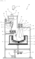
- a single-crystal production equipment 10 of the present Example assumes a case of producing a silicon single crystal having an optimum dopant composition.
- a crucible table 19 In the single-crystal production equipment 10, a crucible table 19, a crucible rotating mechanism 20 and a crucible vertical movement mechanism 22 are arranged on the bottom of a closed chamber 11 which can be vacuum-evacuated and retain an inert gas atmosphere such as argon gas.
- a quartz crucible 12 made of quartz is arranged as a single-crystal production crucible having a substantially circular cross-section, and a carbon holder 16 which mechanically holds the quartz crucible 12 is arranged on the outer side of the quartz crucible 12.
- the closed chamber 11 is a water-cooling structure which is capable of efficiently controlling the inner atmosphere.
- a hopper 33 which stores a granular raw material 52 is arranged.
- the hopper 33 has an opening on its lower part, and a spiral rod (not shown) , which is equipped with a rotating mechanism and coated with polypropylene, is arranged inside the hopper 33 and rotated at all times during use.
- a spiral rod (not shown) , which is equipped with a rotating mechanism and coated with polypropylene, is arranged inside the hopper 33 and rotated at all times during use.
- the opening on the lower part of the hopper 33 is directly connected to the closed chamber 11, and the hopper 33 and the closed chamber 11 are configured in such a manner to have the same internal atmosphere at all times.
- a granular raw material scraping equipment (hereinafter, also simply referred to as "scraping equipment”) 48 is arranged on a lateral side of the opening of the hopper 33.
- This scraping equipment 48 includes a propylene-coated receptacle having a spoon-like shape that is attached to a tip of a rod, and it is configured such that, by inserting this rod to the opening of the hopper 33 and then pulling out and half-rotating the rod with the granular raw material 52 being placed in the receptacle, the granular raw material 52 in the receptacle can be supplied onto a granular raw material quantitative supply equipment (hereinafter, also simply referred to as "quantitative supply equipment”) 50 positioned underneath the hopper 33.
- a granular raw material quantitative supply equipment hereinafter, also simply referred to as "quantitative supply equipment
- the quantitative supply equipment 50 adjusts the amount of the granular raw material 52 to be supplied while measuring the weight thereof and supplies a prescribed amount of the granular raw material 52 to a supply pipe 51 therebelow which has a supply position adjusting function.
- a symbol 60 represents a position adjusting mechanism.
- the hopper 33 in this embodiment stores a granular mixture obtained by mixing dopant-free granular silicon and a granular raw material doped with a dopant at a high concentration such that the granular mixture has an optimum composition, and this enables to surely maintain the composition ratio of the granular raw material 52 constant.
- the hopper 33 is used singly; however, the configuration is not restricted to this mode and, for example, a hopper for storing the dopant-free granular silicon and a hopper for storing the granular raw material doped with a dopant at a high concentration may be separately arranged.
- a known attachment-detachment mechanism 46 is arranged such that a storage container 47 which stores the granular raw material 52 can be attached and detached as desired.
- the attachment-detachment mechanism 46 includes an atmosphere controlling function for arbitrarily controlling the atmospheres inside the attachment-detachment mechanism 46 and the storage container 47.
- FIG. 1 shows a state where the storage container 47 is detached from the hopper 33.
- the storage container 47 that can be attached to and detached from the hopper 33 in this manner, the granular raw material 52 can be supplied to the hopper 33 at any time as required even in the midst of operating the single-crystal production equipment 10 to produce a single crystal. Therefore, it is not necessary to use a large hopper 33, and a reduction in the size of the single-crystal production equipment 10 can be realized.
- the granular raw material 52 supplied from the scraping equipment 48 is supplied to a prescribed position of a granular raw material melting vessel (hereinafter, also referred to as "melting vessel") 62 of a granular raw material melting apparatus through the supply pipe 51 in a prescribed amount using the quantitative supply equipment 50 which has a function of adjusting the supply amount while measuring the weight.
- a granular raw material melting vessel hereinafter, also referred to as "melting vessel”
- the position adjusting mechanism 60 which adjusts the position of an outlet at the lower end of the supply pipe 51, is attached.
- the melting vessel 62 which melts the granular raw material 52, have a multi-section structure divided into a "melting section” where the granular raw material 52 is melted and a “melt retaining section” where the resulting melt is retained; and that the melting vessel 62 have a function of preventing unmelted granular raw material 52 from being supplied downward along with the raw material melt 67.
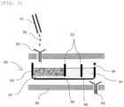
- the melting vessel 62 for example, such a boat-type melting vessel 62 as shown in FIGs. 1 and 3 or such a melting vessel 62 having a two-layer structure (umbrella-like structure) as shown in FIGs. 2 and 4 can be utilized. Further, in the case of producing a silicon single crystal, such a simple-type melting vessel 62 as shown in FIG. 5 can be utilized as well.
- a boat-shaped vessel 61 which receives the granular raw material 52 supplied from the supply pipe 51 is fitted inside a high-frequency induction heating equipment 55.
- a separation plate 63 having a groove 66 on a lower part is arranged inside the boat-shaped vessel 61, and the boat-shaped vessel 61 is divided by the separation plate 63 into the "melting section" and the "melt retaining section".
- the granular raw material 52 to be supplied to the boat-shaped vessel 61 through the supply pipe 51 may be directly supplied into the boat-shaped vessel 61; however, it is preferred to supply the granular raw material 52 into the boat-shaped vessel 61 using a funnel for granular raw material 53 since this makes it easier to supply the granular raw material 52 at a prescribed position.
- the temperature of the boat-shaped vessel is increased, and the granular raw material 52 is thereby heated and melted, as a result of which only the thus formed raw material melt 67 moves to an adjacent section (the section on the right in FIG. 3 ) through the groove 66 on the lower part of the separation plate 63 and is retained therein. It is noted here that the granular raw material 52 is rapidly melted at a temperature that is at least 100°C higher than the melting point of a silicon granular raw material.
- the raw material melt 67 retained in the boat-shaped vessel 61 has reached the height of an outlet 68 arranged on the boat-shaped vessel 61, the raw material melt 67 flows to the outside through the outlet 68 and is thereby dropped into the quartz crucible 12 below.
- the raw material melt 67 discharged from the outlet 68 may be dropped into the quartz crucible 12 below through a funnel for raw material melt 54 as shown in FIG. 3 .
- the unmelted granular raw material 52 can be prevented from being dropped along with the raw material melt 67.
- the melting vessel 62 having a two-layer structure is constituted by a melting dish 64 and a separation dish 65 which is disposed thereon in such a manner to have an inverted V-shaped cross-section, and this melting vessel 62 is configured in such a manner to be divided between the melting dish 64 and the separation dish 65 into a melting section where the granular raw material 52 is melted and a melt retaining section where the resulting raw material melt 67 is retained.
- second infrared ray irradiation equipments 72 and 82 are used, and infrared rays 74 and 85 are irradiated to the melting vessel 62 from these second infrared ray irradiation equipments 72 and 82.
- the second infrared ray irradiation equipments 72 and 82 be arranged above and on a side of the melting vessel 62 as shown in FIG. 2 , respectively; however, they may both be arranged either above or on a side of the melting vessel 62.
- the second infrared ray irradiation equipments 72 and 82 laser irradiation equipments are preferably used; however, other than laser irradiation equipments, the second infrared ray irradiation equipments 72 and 82 may also be resistance heating equipments (particularly, carbon resistance heating equipments in the case of producing a silicon single crystal) , or irradiation apparatuses configured such that, for example, an infrared ray emitted from an infrared lamp is reflected by the inner surface of an elliptical reflector. In this case, as the infrared lamp, a halogen lamp, a xenon lamp or the like can be used.
- the granular raw material 52 is heated and melted, and only the resulting raw material melt 67 moves to the central part through a groove 66 arranged at the lower end of the separation dish 65 and is retained in the separation dish 65.
- the raw material melt 67 retained in the separation dish 65 remains in the central part and, once the raw material melt 67 has reached the height of an outlet 68 arranged on a pipe in the central part, the raw material melt 67 flows into the pipe through the outlet 68 and is thereby dropped into the quartz crucible 12 below. In this process, the unmelted granular raw material 52 can be prevented from dripping down along with the raw material melt 67.
- the simple-type melting vessel 62 stores the granular raw material 52 supplied from the upper end and is constituted by a cylindrical section 57, whose lower end is inserted into a mixed melt 91 on the upper surface of the seed single crystal 14 in the quartz crucible 12, and a funnel-shaped section 58, which is arranged inside the cylindrical section 57 and has an opening at the lower end.
- the second infrared ray irradiation equipments 72 and 82 may be used as in the case of the melting vessel 62 having a two-layer structure (umbrella-like structure) shown in FIG. 2 .
- melting vessel 62 having a two-layer structure (umbrella-like structure) and simple-type melting vessel 62 for example, platinum, iridium, quartz, silicon carbide, carbon, graphite, a carbon or graphite material whose surface has been converted to silicon carbide, or a carbon or graphite material whose surface has been coated with silicon carbide in advance can be selected and used for the entirety or a part of each melting vessel 62.
- the melting vessel 62 having a two-layer structure has a function of being rotated in the horizontal direction by a melting vessel rotating mechanism 70.
- a melting vessel rotating mechanism 70 By rotating the melting vessel 62 having a two-layer structure (umbrella-like structure) in this manner, the granular raw material 52 is evenly supplied from the supply pipe 51 into the melting vessel 62, so that the granular raw material 52 can be surely melted.
- a slope inclined downward toward the center is formed, and a recess 13 for storing the seed single crystal 14 is arranged on the center of the bottom of the quartz crucible 12.
- the slope formed on the bottom of the quartz crucible 12 is inclined downward toward the center at an angle of 3 to 60 degrees (inclination angle), preferably at an angle of 5 to 30 degrees (inclination angle).
- the recess 13 arranged on the center of the bottom of the quartz crucible 12 preferably has, for example, an inner diameter of approximately 20 cm and a height of approximately 20 cm.
- An upper part of the seed single crystal 14 placed therein is melted by irradiation with an infrared ray 28 coming from above; however, a lower part is maintained unmelted.
- a single crystal is allowed to continuously grow only from the remaining seed single crystal 14, whereby a large single crystal can be produced.
- the quartz crucible 12 is used as a single-crystal production crucible; however, the crucible material is selected in accordance with the material of the single crystal to be produced and, other than quartz, for example, platinum, molybdenum, iridium and carbon can be used. Particularly, for the production of a silicon single crystal, a quartz crucible 12 whose inside is coated with a release agent is used as in this embodiment.
- the crucible table 19 on which the quartz crucible 12 is arranged is rotated at a prescribed speed by the crucible rotating mechanism 20, whereby uneven irradiation of the infrared ray into the quartz crucible 12 can be reduced, and a melt phase formed in the quartz crucible 12 is thus allowed to have uniform temperature.
- the height position of the melt phase formed in the quartz crucible 12 can be controlled to be optimal at all times.
- the upper surface of the seed single crystal 14 arranged in the quartz crucible 12 is melted by the infrared ray 28 irradiated from a first infrared ray irradiation equipment (laser irradiation equipment in this embodiment) 26, as a result of which a melt phase is formed.
- a first infrared ray irradiation equipment laser irradiation equipment in this embodiment
- a required amount of a raw material lump adjusted to have the composition of a melt phase that coexists with a solid having this optimum dopant concentration in an equilibrium state is arranged on the seed single crystal 14, and a mixed melt phase is formed first by melting together the raw material lump and an upper part of the seed single crystal 14, after which a mixed melt is further formed by dropping the raw material melt 67 to the mixed melt phase so as to initiate and continuously perform the single-crystal production, whereby a desired single crystal having a uniform composition can be produced.
- the mixed melt phase formed on the seed single crystal 14 arranged in the quartz crucible 12 maintains a constant thickness in accordance with the slope of the bottom of the quartz crucible 12 and, as the single-crystal production continues, the position of the periphery of the mixed melt phase moves to a position away from the center.
- a third infrared ray irradiation equipment (laser irradiation equipment in this embodiment) 30 for local heating is arranged on an upper part of the closed chamber 11.
- the irradiation position of the third infrared ray irradiation equipment 30 is controlled such that the irradiation position of an infrared ray 32 irradiated from the third infrared ray irradiation equipment 30 conforms to the position shift of the periphery of the mixed melt phase.
- the periphery of the mixed melt phase formed in the quartz crucible 12 can be maintained to have a temperature higher than the ambient temperature.
- the periphery of the mixed melt 91 is positioned in the vicinity of the center of the crucible in the initial stage of the single-crystal production; however, it moves toward the outside as the progress of the single-crystal production, and establishes a steady state once it reaches the vertical wall section of the quartz crucible 12.
- the third infrared ray irradiation equipment 30 for local heating has a function of aligning its irradiation position with the position of the moving periphery of the mixed melt phase.
- infrared ray transmitting windows 27, 31, 73 and 84 are arranged, respectively.
- the material of these infrared ray transmitting windows 27, 31, 73 and 84 is not particularly restricted as long as it can transmit infrared rays; however, the infrared ray transmitting windows 27, 31, 73 and 84 are preferably made of, for example, quartz.
- the single-crystal production equipment 10 of the present invention is configured as described above, particularly in such a manner that the granular raw material 52 is converted into the raw material melt 67 using the boat-type melting vessel 62, the melting vessel 62 having a two-layer structure (umbrella-like structure) or the simple-type melting vessel 62 and only the raw material melt 67 is supplied into the quartz crucible 12; therefore, the single-crystal production equipment 10 is capable of producing a large single crystal with no crystal grain boundary, which is a high-quality single crystal that has a uniform composition in both the vertical and horizontal directions at an optimum dopant concentration and contains only a small number of negative crystals and exsolution lamellae.
- a single-crystal production method using the single-crystal production equipment 10 of the present invention will now be described.
- the quartz crucible 12 is arranged in the closed chamber 11.
- the inner surface of the quartz crucible 12 is coated with a release agent.
- a silicon seed single crystal 14 is arranged in the recess 13 arranged in the vicinity of the center on the bottom of the quartz crucible 12 and, on this seed single crystal 14, a granular raw material lump 15 having a composition and an amount that are required for the formation of a melt phase coexisting with a solid having an optimum dopant concentration is arranged.
- the closed chamber 11 is hermetically sealed, and the atmosphere inside the closed chamber 11 is vacuum-evacuated by a gas evacuation unit (not shown), followed by introduction of an inert atmosphere, such as argon gas, into the closed chamber 11.
- a gas evacuation unit not shown
- an inert atmosphere such as argon gas
- the quartz crucible 12 starts to be heated by the auxiliary heating equipment 17, as a result of which the outer circumference of the quartz crucible 12 is heated to a temperature of approximately 1,300°C.
- the auxiliary heating equipment 17 is arranged slightly away from the recess 13 of the quartz crucible 12, the seed single crystal 14 is not subjected to a large amount of heat.
- a melt phase 90 is formed by irradiating the infrared ray 28 to the seed single crystal 14 on the center of the quartz crucible 12 from the first infrared ray irradiation equipment 26.
- the irradiation intensity of the infrared ray 28 is adjusted such that the upper surface of the seed single crystal 14 is also melted together.
- the periphery of the melt phase 90 is irradiated with the infrared ray 32 emitted from the third infrared ray irradiation equipment 30 so as to maintain the periphery to have a temperature that is at least 3°C higher than the ambient temperature.
- the granular raw material scraping equipment 48, the quantitative supply equipment 50 and the second infrared ray irradiation equipments 72 and 82, which are arranged above, are put into operation so as to scrape the granular raw material 52 having an optimum composition out of the hopper 33, feed the granular raw material 52 into the melting vessel 62 through the supply pipe 51 at a prescribed rate, and drop the resulting raw material melt 67 into the quartz crucible 12.
- a mixed melt 91 is formed by the thus dropped raw material melt 67 and the melt formed on the seed single crystal 14.
- the thickness of this mixed melt 91 is increased to a prescribed thickness, since the infrared ray 28 irradiated from the first infrared ray irradiation equipment 26 is unlikely to reach therebelow, the temperature in the vicinity of a solid-liquid interface underneath the mixed melt 91 is lowered.
- the granular raw material 52 having an optimum dopant composition is continuously fed to the melting vessel 62.
- the solid phase continues to precipitate in the lower part of the mixed melt 91 in the quartz crucible 12, and the single crystal 92 thereby continues to grow.
- the temperature is slowly lowered, and the closed chamber 11 is cooled to room temperature and then opened, after which the single crystal 92 is taken out of the quartz crucible 12 as a product.
- the irradiation dose distribution of the infrared ray 28 is designed such that the surface of the single crystal 92 can be maintained as flat as possible throughout the production process.
- the temperature of the periphery of the mixed melt 91 is maintained to be higher than the average temperature of the whole mixed melt 91 by at least 3°C, preferably at least 5°C.
- microcrystals from a release agent-coated part of the inner wall of the quartz crucible 12 or the growth of generated microcrystals can be retarded.
- a granular raw material obtained by mixing the granular raw material 52 composed of a granular crystal base material (granular silicon) and a granular dopant at an optimum composition is used.
- This granular raw material having an optimum composition is stored in the hopper 33 and, using the granular raw material scraping equipment 48 and the quantitative supply equipment 50, the granular raw material 52 is dropped therefrom through the supply pipe 51 into the melting vessel 62, and only the resulting raw material melt 67 is dropped into the quartz crucible 12 below, whereby the processes from the supplying and the melting of the granular raw material 52 to the solidification of a single crystal are continuously performed.
- the granular raw material 52 which is continuously supplied into the melting vessel 62, is heated and melted to obtain the raw material melt 67, and the single crystal 92 is precipitated by supplying the thus obtained raw material melt 67 into the quartz crucible 12; therefore, the resulting single crystal 92 has the same composition as that of the granular raw material 52 having an optimum composition.
- the single crystal 92 being produced is allowed to uniformly have an optimum composition.
- the single-crystal production equipment 10 of the present invention and a single-crystal production method using the single-crystal production equipment 10 have been described thus far; however, the present invention is not restricted to the above-described embodiments.
- a mixed granular raw material which is obtained by mixing a dopant-free high-purity silicon granular raw material and a granular raw material doped with phosphorus at a high concentration such that the resultant has a prescribed optimum composition, is used.
- a mixed granular raw material which is obtained by mixing a dopant-free high-purity silicon granular raw material and a granular raw material doped with boron at a high concentration such that the resultant has a prescribed optimum composition, is used.
- the particles of the granular raw material 52 preferably have a size of approximately 0.1 to 0.5 mm in diameter.
- the granular crystal base material is not restricted thereto, and any granular raw material 52 prepared in accordance with the substance to be produced can be used.
- each constituent such as the infrared ray irradiation equipments 26, 30, 72 and 82 each irradiating an infrared ray, the melting vessel 62, the quantitative supply equipment 50, the granular raw material scraping equipment 48 and the supply pipe 51, a case where these constituents are each arranged singly was described; however, each constituent may be arranged in a plural number in accordance with the size of a single crystal to be grown, and the number of each constituent can be set as appropriate.
- a mode of triplex structure is adopted for the boat-shaped melting vessel 62; however, other structure may also be adopted and, for example, the melting vessel 62 shown in Fig. 4 can be used as well.
- the granular raw material scraping equipment 48 and the supply pipe 51 are used as granular raw material supply apparatus; however, they may be omitted depending on the case and, in such a case, the granular raw material 52 may be directly supplied to the melting vessel 62 from the quantitative supply equipment 50.
Landscapes
- Chemical & Material Sciences (AREA)
- Engineering & Computer Science (AREA)
- Crystallography & Structural Chemistry (AREA)
- Materials Engineering (AREA)
- Metallurgy (AREA)
- Organic Chemistry (AREA)
- Physics & Mathematics (AREA)
- Electromagnetism (AREA)
- Crystals, And After-Treatments Of Crystals (AREA)
Claims (24)
- Einkristallproduktionsgerät (10) zum Herstellen eines großen Einkristalls durch Platzieren eines Saat-Einkristalls in einen Einkristallproduktionstiegel (12), Zuführen einer Rohstoffschmelze (67), die durch Schmelzen eines Granulatrohstoffs (52) unter Verwendung einer Granulatrohstoff-Schmelzvorrichtung erhalten wurde, in den Einkristallproduktionstiegel (12) und Ausfällen eines Einkristalls (92) als Feststoff auf dem Saat-Einkristall (14),wobei der Einkristallproduktionstiegel (12) derart eingerichtet ist, dass eine Vertiefung (13) an einem zentralen Teil des Bodens gebildet ist, und der Saat-Einkristall (14) in der Vertiefung (13) angeordnet ist undwobei das Einkristallproduktionsgerät (10) mindestens aufweist:wobei das Granulatrohstoff-Schmelzgefäß aus der Gruppe ausgewählt ist, die besteht aus:eine Granulatrohstoff-Zufuhrvorrichtung, die eine bestimmte Menge des Granulatrohstoffs (52) an eine darunter positionierte Granulatrohstoff-Schmelzvorrichtung zuführt;die Granulatrohstoff-Schmelzvorrichtung, die den von der Granulatrohstoff-Zufuhrvorrichtung zugeführten Granulatrohstoff (52) erhitzt und schmilzt, um eine Rohstoffschmelze (67) zu erzeugen, und die Rohstoffschmelze (67) in den darunter positionierten Einkristallproduktionstiegel (12) zuführt; undeine Kristallisationsvorrichtung, die den Einkristallproduktionstiegel (12) aufweist, auf dessen Boden der Saat-Einkristall (14) platziert ist, und ein erstes Infrarotbestrahlungsgerät (26), das einen Infrarotstrahl (28) auf die obere Oberfläche des Saat-Einkristalls (14) in dem Einkristallproduktionstiegel (12) strahlt, unddas Einkristallproduktionsgerät (10) derart eingerichtet ist, dass die von der Granulatrohstoff-Schmelzvorrichtung zugeführte Rohstoffschmelze (67) in eine Schmelze eingelassen wird, die durch Bestrahlen der oberen Oberfläche des Saat-Einkristalls (14) mit dem Infrarotstrahl (28) gebildet wird, und ein Einkristall (92) aus der derart gebildeten gemischten Schmelze (91) ausfällt;wobei die Granulatrohstoff-Schmelzvorrichtung aufweist:ein Granulatrohstoff-Schmelzgefäß (62), das den Granulatrohstoff (52) aufnimmt, undein Gefäßheizgerät, das das Granulatrohstoff-Schmelzgefäß (62) erhitzt und dadurch den Granulatrohstoff (52) in dem Granulatrohstoff-Schmelzgefäß (62) schmilzt;wobei das Granulatrohstoff-Schmelzgefäß (62) aufweist:einen Schmelzabschnitt, in dem der Granulatrohstoff (52) erhitzt und geschmolzen wird, undeinen schmelzehaltenden Abschnitt, in welchem nur eine in dem Schmelzabschnitt erzeugte Schmelze gehalten wird; undeinem bootförmigen Gefäß (61) undeiner Trennplatte (63), die das bootförmige Gefäß (61) in den Schmelzabschnitt und den schmelzehaltenden Abschnitt teilt und an einem unteren Teil eine Nut (66) aufweist; odereiner Schmelzschale (64) undeiner Trennschale (65), die innerhalb der Schmelzschale (64) angeordnet ist und einen Querschnitt in Form eines umgekehrten V aufweist und an einem unteren Teil eine Nut (66) aufweist, wobeidas Granulatrohstoff-Schmelzgefäß derart eingerichtet ist, dass es zwischen der Schmelzschale (64) und der Trennschale (65) in den Schmelzabschnitt und den schmelzehaltenden Abschnitt geteilt ist; odereinem zylindrischen Abschnitt (57) undeinem trichterförmigen Abschnitt (57), der in dem zylindrischen Abschnitt (57) angeordnet ist und an einem unteren Ende eine Öffnung aufweist, wobeidie innere Seite des zylindrischen Abschnitts (57) den Schmelzabschnitt bildet und ein Raum zwischen der äußeren Seite des zylindrischen Abschnitts (57) und dem trichterförmigen Abschnitt (58) den schmelzehaltenden Abschnitt bildet.
- Einkristallproduktionsgerät (10) nach Anspruch 1, wobei die Granulatrohstoff-Zufuhrvorrichtung aufweist:einen Schüttgutbehälter (33), in dem der Granulatrohstoff (52) gelagert ist; undein Gerät (50) zur quantitativen Zufuhr von Granulatrohstoff, das den Granulatrohstoff in dem Schüttgutbehälter (33) derart steuert, dass er mit einer vorbestimmten Rate zugeführt wird, und eine bestimmte Menge des Granulatrohstoffs (52) nach unten zuführt.
- Einkristallproduktionsgerät (10) nach Anspruch 1 oder 2, wobei die Granulatrohstoff-Zufuhrvorrichtung ein Granulatrohstoff-Schabegerät (48) aufweist, das den Granulatrohstoff (52) aus dem Schüttgutbehälter (33) schabt und den Granulatrohstoff nach unten zuführt.
- Einkristallproduktionsgerät (10) nach Anspruch 2 oder 3, wobei die Granulatrohstoff-Zufuhrvorrichtung ein Zufuhrrohr (51) aufweist, durch welches der Granulatrohstoff (52), der von dem Gerät (50) zur quantitativen Zufuhr von Granulatrohstoff zugeführt wird, an eine vorbestimmte Position der darunter befindlichen Granulatrohstoff-Schmelzvorrichtung zugeführt wird.
- Einkristallproduktionsgerät (10) nach Anspruch 4, wobei ein Material des Zufuhrrohrs (51) Quarz ist.
- Einkristallproduktionsgerät (10) nach Anspruch 2, wobei der Schüttgutbehälter (33) einen Befestigungs-/Abtrenn-Mechanismus (46) zum Befestigen und Abtrennen eines Lagerbehälters (47) aufweist, in dem der Granulatrohstoff (52) lagert.
- Einkristallproduktionsgerät (10) nach Anspruch 6, wobei der Befestigungs-/Abtrenn-Mechanismus (46) eine Atmosphärenregelungsfunktion aufweist, die die Atmosphäre innerhalb des Befestigungs-/Abtrenn-Mechanismus (46) und des Lagerbehälters (47) beliebig steuert.
- Einkristallproduktionsgerät (10) nach einem der Ansprüche 1 bis 7, wobei die Granulatrohstoff-Schmelzvorrichtung und die Kristallisationsvorrichtung innerhalb einer geschlossenen Kammer (11) angeordnet sind.
- Einkristallproduktionsgerät (10) nach Anspruch 8, wobei die Granulatrohstoff-Zufuhrvorrichtung innerhalb der geschlossenen Kammer (11) angeordnet ist.
- Einkristallproduktionsgerät (10) nach Anspruch 8 oder 9, das ein Atmosphärenregelungsgerät aufweist, welches das Innere des Schüttgutbehälters (33) mit der geschlossenen Kammer (11) verbindet oder das Innere des Schüttgutbehälters (33) und der geschlossenen Kammer (11) regelt, sodass sie die gleiche Atmosphäre aufweisen.
- Einkristallproduktionsgerät (10) nach einem der Ansprüche 2 bis 10, wobei der Schüttgutbehälter (33) von mehreren Schüttgutbehältern (33) gebildet wird, in denen jeweils Granulatrohstoffe (52) unterschiedlicher Zusammensetzung gelagert sind.
- Einkristallproduktionsgerät (10) nach Anspruch 1, wobei das Gefäßheizgerät ein zweites Infrarotbestrahlungsgerät (72) ist.
- Einkristallproduktionsgerät (10) nach Anspruch 1, wobei das Gefäßheizgerät ein Hochfrequenz-Induktionsheizgerät ist.
- Einkristallproduktionsgerät (10) nach Anspruch 1, wobei das Gefäßheizgerät ein Widerstandsheizgerät ist.
- Einkristallproduktionsgerät (10) nach Anspruch 1, wobei das Granulatrohstoff-Schmelzgefäß einen Schmelzgefäß-Drehmechanismus (70) aufweist, der sich in horizontaler Richtung dreht.
- Einkristallproduktionsgerät (10) nach einem der Ansprüche 1 und 12 bis 15, wobei ein Teil oder die Gesamtheit des Granulatrohstoff-Schmelzgefäßes aus Platin, Iridium, Quarz, Siliziumkarbid, Kohlenstoff, Grafit, einem Kohlenstoff- oder Grafitmaterial, dessen Oberfläche in Siliziumkarbid umgewandelt wurde, oder einem Kohlenstoff- oder Grafitmaterial, dessen Oberfläche im Voraus mit Siliziumkarbid beschichtet wurde, besteht.
- Einkristallproduktionsgerät (10) nach einem der Ansprüche 1 bis 16, das mehrere der Granulatrohstoff-Zufuhrvorrichtungen aufweist.
- Einkristallproduktionsgerät (10) nach Anspruch 17, das mehrere der Granulatrohstoff-Schmelzvorrichtungen aufweist.
- Einkristallproduktionsgerät (10) nach einem der Ansprüche 1 bis 18, wobei ein Hilfsheizgerät (17) an der Außenseite des Einkristallproduktionstiegels (12) angeordnet ist.
- Einkristallproduktionsgerät (10) nach einem der Ansprüche 1 bis 19, wobei ein drittes Infrarotbestrahlungsgerät (30), das die Umgebung der Peripherie einer Schmelze und/oder einer gemischten Schmelze (91) in dem Einkristallproduktionstiegel (12) erhitzt, über dem Einkristallproduktionstiegel (12) angeordnet ist.
- Einkristallproduktionsgerät (10) nach einem der Ansprüche 1 bis 20, wobei der Boden des Einkristallproduktionstiegels (12) zur Mitte hin nach unten geneigt ist.
- Einkristallproduktionsgerät (10) nach einem der Ansprüche 1 bis 21, wobei die innere Wand des Einkristallproduktionstiegels (12) mit einem Trennmittel beschichtet ist.
- Einkristallproduktionsgerät (10) nach einem der Ansprüche 1 bis 22, wobei der Einkristallproduktionstiegel (12) einen Tiegel-Drehmechanismus (20) aufweist, der sich in horizontaler Richtung dreht.
- Einkristallproduktionsgerät (10) nach einem der Ansprüche 1 bis 23, wobei der Einkristallproduktionstiegel eine Hebevorrichtung aufweist, die sich mit einer vorbestimmten Geschwindigkeit in vertikaler Richtung bewegt.
Applications Claiming Priority (1)
| Application Number | Priority Date | Filing Date | Title |
|---|---|---|---|
| PCT/JP2018/013163 WO2019186871A1 (ja) | 2018-03-29 | 2018-03-29 | 単結晶製造装置および単結晶製造方法 |
Publications (3)
| Publication Number | Publication Date |
|---|---|
| EP3572560A1 EP3572560A1 (de) | 2019-11-27 |
| EP3572560A4 EP3572560A4 (de) | 2020-01-22 |
| EP3572560B1 true EP3572560B1 (de) | 2024-09-11 |
Family
ID=68056918
Family Applications (1)
| Application Number | Title | Priority Date | Filing Date |
|---|---|---|---|
| EP18785795.8A Active EP3572560B1 (de) | 2018-03-29 | 2018-03-29 | Einkristallherstellungsvorrichtung |
Country Status (5)
| Country | Link |
|---|---|
| US (1) | US11326270B2 (de) |
| EP (1) | EP3572560B1 (de) |
| JP (1) | JP6607652B1 (de) |
| CN (1) | CN110546315B (de) |
| WO (1) | WO2019186871A1 (de) |
Families Citing this family (2)
| Publication number | Priority date | Publication date | Assignee | Title |
|---|---|---|---|---|
| CN111924811A (zh) * | 2020-07-02 | 2020-11-13 | 清远先导材料有限公司 | 一种超高纯碲的制备方法 |
| CN112680790A (zh) * | 2020-12-07 | 2021-04-20 | 宁波建锡新材料有限公司 | 一种磷化铟半导体材料的合成方法 |
Family Cites Families (63)
| Publication number | Priority date | Publication date | Assignee | Title |
|---|---|---|---|---|
| NL8005312A (nl) | 1980-09-24 | 1982-04-16 | Philips Nv | Werkwijze voor het vervaardigen van ferriet eenkristallen. |
| JPS5915056U (ja) | 1982-07-16 | 1984-01-30 | コニカ株式会社 | 現像剤補給容器 |
| JPS61197493A (ja) | 1985-02-26 | 1986-09-01 | Kyozo Kaneko | 金属酸化物の結晶化方法 |
| US5116456A (en) | 1988-04-18 | 1992-05-26 | Solon Technologies, Inc. | Apparatus and method for growth of large single crystals in plate/slab form |
| EP0450494B1 (de) | 1990-03-30 | 1996-06-19 | Sumitomo Sitix Corporation | Verfahren zur Herstellung eines Siliziumeinkristalles |
| US5108720A (en) | 1991-05-20 | 1992-04-28 | Hemlock Semiconductor Corporation | Float zone processing of particulate silicon |
| US5178719A (en) | 1991-08-20 | 1993-01-12 | Horiba Instruments, Inc. | Continuous refill crystal growth method |
| JP2754104B2 (ja) * | 1991-10-15 | 1998-05-20 | 信越半導体株式会社 | 半導体単結晶引上用粒状原料供給装置 |
| WO1993012272A1 (fr) | 1991-12-18 | 1993-06-24 | Nobuyuki Mori | Procede et appareil de coulee d'un lingot de silicium cristallin par fusion par bombardement electronique |
| JP3053958B2 (ja) | 1992-04-10 | 2000-06-19 | 光弘 丸山 | 浮遊帯溶融法による結晶の製造装置 |
| DE4218123C2 (de) * | 1992-06-02 | 1996-05-02 | Leybold Ag | Vorrichtung für die kontinuierliche Zuführung von Chargengut für einen Schmelztiegel und deren Verwendung |
| JPH06100394A (ja) * | 1992-09-17 | 1994-04-12 | Nkk Corp | 単結晶製造用原料供給方法及び装置 |
| JP2831906B2 (ja) | 1993-06-08 | 1998-12-02 | 日鉄鉱業株式会社 | 単結晶製造装置 |
| DE4323793A1 (de) | 1993-07-15 | 1995-01-19 | Wacker Chemitronic | Verfahren zur Herstellung von Stäben oder Blöcken aus beim Erstarren sich ausdehnendem Halbleitermaterial durch Kristallisieren einer aus Granulat erzeugten Schmelze sowie Vorrichtung zu seiner Durchführung |
| US5762707A (en) | 1995-09-18 | 1998-06-09 | Cristal Systems, Inc. | Floating zone melting apparatus |
| JP3011114B2 (ja) | 1996-01-12 | 2000-02-21 | 住友金属工業株式会社 | シリコン溶融用坩堝 |
| TW429273B (en) | 1996-02-08 | 2001-04-11 | Shinetsu Handotai Kk | Method for feeding garnular silicon material, feed pipe used in the method, and method of manufacturing a silicon monocrystal |
| JP2937108B2 (ja) * | 1996-02-23 | 1999-08-23 | 住友金属工業株式会社 | 単結晶引き上げ方法及び単結晶引き上げ装置 |
| DE19607098C2 (de) * | 1996-02-24 | 1999-06-17 | Ald Vacuum Techn Gmbh | Verfahren und Vorrichtung zum gerichteten Erstarren einer Schmelze aus Silizium zu einem Block in einem bodenlosen metallischen Kaltwandtiegel |
| KR100293095B1 (ko) | 1996-02-29 | 2001-10-25 | 고지마 마타오 | 단결정향상방법과 단결정향상장치 |
| JPH10273374A (ja) * | 1997-03-27 | 1998-10-13 | Kawasaki Steel Corp | シリコンの精製方法 |
| US5919306A (en) | 1997-11-03 | 1999-07-06 | Sumitomo Sitix Corporation | Silicon melting crucible |
| DE19882384T1 (de) * | 1998-03-12 | 2000-07-27 | Super Silicon Crystal Res Inst | Zusatzschmelzvorrichtung für einkristallines Material und Verfahren zum Schmelzen von einkristallinem Material |
| JPH11274537A (ja) * | 1998-03-24 | 1999-10-08 | Tokyo Denshi Yakin Kenkyusho:Kk | 大粒径多結晶シリコンの製造法 |
| JPH11292682A (ja) * | 1998-04-02 | 1999-10-26 | Shin Etsu Handotai Co Ltd | シリコン単結晶の製造方法および製造装置 |
| RU2215070C2 (ru) | 1998-05-29 | 2003-10-27 | Тойо Коммьюникейшн Эквипмент Ко., Лтд. | Устройство для получения монокристалла (варианты), способ получения монокристалла (варианты) и монокристалл (варианты) |
| US6325849B1 (en) | 1998-07-07 | 2001-12-04 | Mitsubishi Chemical Corporation | P-type gaas single crystal and method for manufacturing the same |
| JP2001151595A (ja) | 1999-11-19 | 2001-06-05 | Murata Mfg Co Ltd | 単結晶製造方法および製造装置 |
| DE60037944T2 (de) | 2000-12-28 | 2009-01-22 | Sumco Corp. | Kontinuierliches giessverfahren für silizium |
| JP4092398B2 (ja) | 2002-12-11 | 2008-05-28 | 独立行政法人産業技術総合研究所 | アルカリコバルト酸化物のバルク状単結晶 |
| CN1330798C (zh) | 2004-05-31 | 2007-08-08 | 南开大学 | 熔体注入法生长近化学比铌酸锂晶体系统及其工艺 |
| JP4317575B2 (ja) | 2005-08-19 | 2009-08-19 | Sumcoソーラー株式会社 | シリコン電磁鋳造装置およびその操作方法 |
| US7427327B2 (en) | 2005-09-08 | 2008-09-23 | Heraeus Shin-Etsu America, Inc. | Silica glass crucible with barium-doped inner wall |
| US7383696B2 (en) | 2005-09-08 | 2008-06-10 | Heraeus Shin-Etsu America, Inc. | Silica glass crucible with bubble-free and reduced bubble growth wall |
| US20070056504A1 (en) | 2005-09-12 | 2007-03-15 | Rexor Corporation | Method and apparatus to produce single crystal ingot of uniform axial resistivity |
| KR101400075B1 (ko) * | 2006-01-20 | 2014-05-28 | 에이엠지 아이디얼캐스트 솔라 코포레이션 | 광전 변환 소자용 기하학적 다결정 캐스트 실리콘 및 기하학적 다결정 캐스트 실리콘 바디들을 제조하는 방법 및 장치 |
| TWI408259B (zh) | 2006-09-28 | 2013-09-11 | Shinetsu Quartz Prod | 具有鋇摻雜內壁的矽玻璃坩堝 |
| KR101157311B1 (ko) | 2007-01-10 | 2012-06-15 | 크리스탈 시스템스 코포레이션 | 부유대역용융장치 |
| US8262797B1 (en) * | 2007-03-13 | 2012-09-11 | Solaicx, Inc. | Weir design providing optimal purge gas flow, melt control, and temperature stabilization for improved single crystal growth in a continuous Czochralski process |
| DE102007038851A1 (de) | 2007-08-16 | 2009-02-19 | Schott Ag | Verfahren zur Herstellung von monokristallinen Metall- oder Halbmetallkörpern |
| US20100307406A1 (en) | 2007-12-25 | 2010-12-09 | Isamu Shindo | Floating zone melting apparatus |
| CN101555620A (zh) | 2008-04-07 | 2009-10-14 | Axt公司 | 晶体生长装置及方法 |
| US20110259262A1 (en) * | 2008-06-16 | 2011-10-27 | Gt Solar, Inc. | Systems and methods for growing monocrystalline silicon ingots by directional solidification |
| CN101736401B (zh) * | 2008-11-10 | 2013-07-24 | Axt公司 | 锗晶体生长的方法和装置 |
| JP4307516B1 (ja) | 2008-11-25 | 2009-08-05 | 佑吉 堀岡 | 結晶成長装置及び結晶成長方法 |
| RU2418109C1 (ru) | 2009-11-09 | 2011-05-10 | Инновационно-технический центр Общество с ограниченной ответственностью "СИТИС" | Установка для получения монокристаллов |
| US8652257B2 (en) | 2010-02-22 | 2014-02-18 | Lev George Eidelman | Controlled gravity feeding czochralski apparatus with on the way melting raw material |
| CN102859050B (zh) * | 2010-03-29 | 2015-07-15 | 住友电气工业株式会社 | 制造半导体单晶的方法 |
| JP5637221B2 (ja) | 2010-12-28 | 2014-12-10 | 宇部興産株式会社 | 多結晶シリコンインゴット鋳造用鋳型及びその製造方法並びに多結晶シリコンインゴット鋳造用鋳型の離型材用窒化珪素粉末及びそれを含有したスラリー |
| US8684151B2 (en) | 2011-03-09 | 2014-04-01 | Sinfonia Technology Co., Ltd. | Raw material loading apparatus and pipe unit for raw material loading apparatus |
| KR101216521B1 (ko) * | 2012-03-20 | 2012-12-31 | 유호정 | 피드유닛을 구비하는 실리콘 잉곳 성장 장치 |
| JP2014076915A (ja) | 2012-10-10 | 2014-05-01 | Electronics & Materials Corporation Ltd | 半導体結晶成長容器、およびそれにより成長させた結晶から得られるウエハを用いて作製した太陽電池 |
| JP6126370B2 (ja) * | 2012-12-12 | 2017-05-10 | 三光機械株式会社 | 粒状原料供給装置 |
| JP6075625B2 (ja) | 2013-01-22 | 2017-02-08 | 京セラ株式会社 | シリコン用鋳造装置およびシリコンの鋳造方法 |
| WO2014185572A1 (ko) | 2013-05-16 | 2014-11-20 | (주)에스테크 | 잉곳 원료 공급시스템 |
| US9845548B2 (en) | 2013-09-30 | 2017-12-19 | Gtat Corporation | Advanced crucible support and thermal distribution management |
| US10358740B2 (en) | 2014-07-25 | 2019-07-23 | Corner Star Limited | Crystal growing systems and methods including a passive heater |
| CN104328483A (zh) | 2014-11-13 | 2015-02-04 | 吴晟 | 一种单晶生长方法及装置 |
| US20160230307A1 (en) | 2015-02-05 | 2016-08-11 | Solarworld Industries America Inc. | Apparatus and methods for producing silicon-ingots |
| US20160348271A1 (en) | 2015-05-29 | 2016-12-01 | Jagannathan Ravi | Integrated System of Silicon Casting and Float Zone Crystallization |
| JP6629886B2 (ja) * | 2016-06-29 | 2020-01-15 | 株式会社クリスタルシステム | 単結晶製造装置 |
| WO2018020821A1 (ja) * | 2016-07-28 | 2018-02-01 | 株式会社クリスタルシステム | 単結晶製造装置 |
| US10415149B2 (en) * | 2017-03-31 | 2019-09-17 | Silfex, Inc. | Growth of a shaped silicon ingot by feeding liquid onto a shaped ingot |
-
2018
- 2018-03-29 WO PCT/JP2018/013163 patent/WO2019186871A1/ja not_active Ceased
- 2018-03-29 EP EP18785795.8A patent/EP3572560B1/de active Active
- 2018-03-29 US US16/303,297 patent/US11326270B2/en active Active
- 2018-03-29 JP JP2018537688A patent/JP6607652B1/ja active Active
- 2018-03-29 CN CN201880001872.6A patent/CN110546315B/zh active Active
Also Published As
| Publication number | Publication date |
|---|---|
| JP6607652B1 (ja) | 2019-11-20 |
| EP3572560A4 (de) | 2020-01-22 |
| US11326270B2 (en) | 2022-05-10 |
| CN110546315A (zh) | 2019-12-06 |
| EP3572560A1 (de) | 2019-11-27 |
| JPWO2019186871A1 (ja) | 2020-04-30 |
| WO2019186871A1 (ja) | 2019-10-03 |
| CN110546315B (zh) | 2021-09-03 |
| US20190301050A1 (en) | 2019-10-03 |
Similar Documents
| Publication | Publication Date | Title |
|---|---|---|
| CN102758249B (zh) | 一种无色刚玉单晶的制备方法 | |
| JP6629886B2 (ja) | 単結晶製造装置 | |
| CN102277618B (zh) | 多晶硅锭的制造方法 | |
| CN102084037A (zh) | 通过定向固化生长单晶硅锭的系统及方法 | |
| CN102268724A (zh) | 多晶硅锭及其制造方法、太阳能电池 | |
| US20210222320A1 (en) | Method of Producing a Single-Crystal | |
| JP5731349B2 (ja) | 単結晶シリコンにおける連続的成長用システム | |
| CN102312279A (zh) | 籽晶诱导的晶体铸造方法 | |
| CN102260900A (zh) | 提高单晶硅纵向电阻率一致性的装置及其处理工艺 | |
| EP3572560B1 (de) | Einkristallherstellungsvorrichtung | |
| CN202144523U (zh) | 一种提高单晶硅纵向电阻率一致性的装置 | |
| CN102776556A (zh) | 一种多晶硅锭及其制备方法和多晶硅片 | |
| KR101271649B1 (ko) | 단결정 실리콘 시드를 이용한 고품질 다결정 실리콘 잉곳의 제조방법 | |
| EP3572559B1 (de) | Einkristallherstellungsvorrichtung | |
| CN118407112A (zh) | 垂直布里奇曼法制备的大体积铯铅溴单晶及其制备方法和应用 | |
| CN118773718A (zh) | 一种磷化铟单晶的制备方法和磷化铟单晶生长用阶梯式坩埚 | |
| JP2008087972A (ja) | シリコン単結晶の製造方法 |
Legal Events
| Date | Code | Title | Description |
|---|---|---|---|
| STAA | Information on the status of an ep patent application or granted ep patent |
Free format text: STATUS: UNKNOWN |
|
| STAA | Information on the status of an ep patent application or granted ep patent |
Free format text: STATUS: THE INTERNATIONAL PUBLICATION HAS BEEN MADE |
|
| PUAI | Public reference made under article 153(3) epc to a published international application that has entered the european phase |
Free format text: ORIGINAL CODE: 0009012 |
|
| STAA | Information on the status of an ep patent application or granted ep patent |
Free format text: STATUS: REQUEST FOR EXAMINATION WAS MADE |
|
| 17P | Request for examination filed |
Effective date: 20181024 |
|
| AK | Designated contracting states |
Kind code of ref document: A1 Designated state(s): AL AT BE BG CH CY CZ DE DK EE ES FI FR GB GR HR HU IE IS IT LI LT LU LV MC MK MT NL NO PL PT RO RS SE SI SK SM TR |
|
| AX | Request for extension of the european patent |
Extension state: BA ME |
|
| A4 | Supplementary search report drawn up and despatched |
Effective date: 20191220 |
|
| RIC1 | Information provided on ipc code assigned before grant |
Ipc: C30B 11/00 20060101ALI20191216BHEP Ipc: C30B 11/08 20060101ALI20191216BHEP Ipc: C30B 13/00 20060101AFI20191216BHEP |
|
| STAA | Information on the status of an ep patent application or granted ep patent |
Free format text: STATUS: EXAMINATION IS IN PROGRESS |
|
| 17Q | First examination report despatched |
Effective date: 20210406 |
|
| DAV | Request for validation of the european patent (deleted) | ||
| DAX | Request for extension of the european patent (deleted) | ||
| GRAP | Despatch of communication of intention to grant a patent |
Free format text: ORIGINAL CODE: EPIDOSNIGR1 |
|
| STAA | Information on the status of an ep patent application or granted ep patent |
Free format text: STATUS: GRANT OF PATENT IS INTENDED |
|
| INTG | Intention to grant announced |
Effective date: 20240412 |
|
| GRAS | Grant fee paid |
Free format text: ORIGINAL CODE: EPIDOSNIGR3 |
|
| P01 | Opt-out of the competence of the unified patent court (upc) registered |
Free format text: CASE NUMBER: APP_39665/2024 Effective date: 20240703 |
|
| GRAA | (expected) grant |
Free format text: ORIGINAL CODE: 0009210 |
|
| STAA | Information on the status of an ep patent application or granted ep patent |
Free format text: STATUS: THE PATENT HAS BEEN GRANTED |
|
| AK | Designated contracting states |
Kind code of ref document: B1 Designated state(s): AL AT BE BG CH CY CZ DE DK EE ES FI FR GB GR HR HU IE IS IT LI LT LU LV MC MK MT NL NO PL PT RO RS SE SI SK SM TR |
|
| REG | Reference to a national code |
Ref country code: GB Ref legal event code: FG4D |
|
| REG | Reference to a national code |
Ref country code: CH Ref legal event code: EP |
|
| REG | Reference to a national code |
Ref country code: DE Ref legal event code: R096 Ref document number: 602018074286 Country of ref document: DE |
|
| REG | Reference to a national code |
Ref country code: IE Ref legal event code: FG4D |
|
| REG | Reference to a national code |
Ref country code: LT Ref legal event code: MG9D |
|
| PG25 | Lapsed in a contracting state [announced via postgrant information from national office to epo] |
Ref country code: NO Free format text: LAPSE BECAUSE OF FAILURE TO SUBMIT A TRANSLATION OF THE DESCRIPTION OR TO PAY THE FEE WITHIN THE PRESCRIBED TIME-LIMIT Effective date: 20241211 |
|
| REG | Reference to a national code |
Ref country code: NL Ref legal event code: MP Effective date: 20240911 |
|
| PG25 | Lapsed in a contracting state [announced via postgrant information from national office to epo] |
Ref country code: GR Free format text: LAPSE BECAUSE OF FAILURE TO SUBMIT A TRANSLATION OF THE DESCRIPTION OR TO PAY THE FEE WITHIN THE PRESCRIBED TIME-LIMIT Effective date: 20241212 Ref country code: FI Free format text: LAPSE BECAUSE OF FAILURE TO SUBMIT A TRANSLATION OF THE DESCRIPTION OR TO PAY THE FEE WITHIN THE PRESCRIBED TIME-LIMIT Effective date: 20240911 |
|
| PG25 | Lapsed in a contracting state [announced via postgrant information from national office to epo] |
Ref country code: BG Free format text: LAPSE BECAUSE OF FAILURE TO SUBMIT A TRANSLATION OF THE DESCRIPTION OR TO PAY THE FEE WITHIN THE PRESCRIBED TIME-LIMIT Effective date: 20240911 |
|
| PG25 | Lapsed in a contracting state [announced via postgrant information from national office to epo] |
Ref country code: LV Free format text: LAPSE BECAUSE OF FAILURE TO SUBMIT A TRANSLATION OF THE DESCRIPTION OR TO PAY THE FEE WITHIN THE PRESCRIBED TIME-LIMIT Effective date: 20240911 |
|
| PG25 | Lapsed in a contracting state [announced via postgrant information from national office to epo] |
Ref country code: HR Free format text: LAPSE BECAUSE OF FAILURE TO SUBMIT A TRANSLATION OF THE DESCRIPTION OR TO PAY THE FEE WITHIN THE PRESCRIBED TIME-LIMIT Effective date: 20240911 |
|
| PG25 | Lapsed in a contracting state [announced via postgrant information from national office to epo] |
Ref country code: ES Free format text: LAPSE BECAUSE OF FAILURE TO SUBMIT A TRANSLATION OF THE DESCRIPTION OR TO PAY THE FEE WITHIN THE PRESCRIBED TIME-LIMIT Effective date: 20240911 Ref country code: RS Free format text: LAPSE BECAUSE OF FAILURE TO SUBMIT A TRANSLATION OF THE DESCRIPTION OR TO PAY THE FEE WITHIN THE PRESCRIBED TIME-LIMIT Effective date: 20241211 |
|
| PG25 | Lapsed in a contracting state [announced via postgrant information from national office to epo] |
Ref country code: RS Free format text: LAPSE BECAUSE OF FAILURE TO SUBMIT A TRANSLATION OF THE DESCRIPTION OR TO PAY THE FEE WITHIN THE PRESCRIBED TIME-LIMIT Effective date: 20241211 Ref country code: NO Free format text: LAPSE BECAUSE OF FAILURE TO SUBMIT A TRANSLATION OF THE DESCRIPTION OR TO PAY THE FEE WITHIN THE PRESCRIBED TIME-LIMIT Effective date: 20241211 Ref country code: LV Free format text: LAPSE BECAUSE OF FAILURE TO SUBMIT A TRANSLATION OF THE DESCRIPTION OR TO PAY THE FEE WITHIN THE PRESCRIBED TIME-LIMIT Effective date: 20240911 Ref country code: HR Free format text: LAPSE BECAUSE OF FAILURE TO SUBMIT A TRANSLATION OF THE DESCRIPTION OR TO PAY THE FEE WITHIN THE PRESCRIBED TIME-LIMIT Effective date: 20240911 Ref country code: GR Free format text: LAPSE BECAUSE OF FAILURE TO SUBMIT A TRANSLATION OF THE DESCRIPTION OR TO PAY THE FEE WITHIN THE PRESCRIBED TIME-LIMIT Effective date: 20241212 Ref country code: FI Free format text: LAPSE BECAUSE OF FAILURE TO SUBMIT A TRANSLATION OF THE DESCRIPTION OR TO PAY THE FEE WITHIN THE PRESCRIBED TIME-LIMIT Effective date: 20240911 Ref country code: ES Free format text: LAPSE BECAUSE OF FAILURE TO SUBMIT A TRANSLATION OF THE DESCRIPTION OR TO PAY THE FEE WITHIN THE PRESCRIBED TIME-LIMIT Effective date: 20240911 Ref country code: BG Free format text: LAPSE BECAUSE OF FAILURE TO SUBMIT A TRANSLATION OF THE DESCRIPTION OR TO PAY THE FEE WITHIN THE PRESCRIBED TIME-LIMIT Effective date: 20240911 |
|
| REG | Reference to a national code |
Ref country code: AT Ref legal event code: MK05 Ref document number: 1722741 Country of ref document: AT Kind code of ref document: T Effective date: 20240911 |
|
| PG25 | Lapsed in a contracting state [announced via postgrant information from national office to epo] |
Ref country code: NL Free format text: LAPSE BECAUSE OF FAILURE TO SUBMIT A TRANSLATION OF THE DESCRIPTION OR TO PAY THE FEE WITHIN THE PRESCRIBED TIME-LIMIT Effective date: 20240911 |
|
| PG25 | Lapsed in a contracting state [announced via postgrant information from national office to epo] |
Ref country code: PT Free format text: LAPSE BECAUSE OF FAILURE TO SUBMIT A TRANSLATION OF THE DESCRIPTION OR TO PAY THE FEE WITHIN THE PRESCRIBED TIME-LIMIT Effective date: 20250113 Ref country code: IS Free format text: LAPSE BECAUSE OF FAILURE TO SUBMIT A TRANSLATION OF THE DESCRIPTION OR TO PAY THE FEE WITHIN THE PRESCRIBED TIME-LIMIT Effective date: 20250111 |
|
| PGFP | Annual fee paid to national office [announced via postgrant information from national office to epo] |
Ref country code: DE Payment date: 20250326 Year of fee payment: 8 |
|
| PG25 | Lapsed in a contracting state [announced via postgrant information from national office to epo] |
Ref country code: RO Free format text: LAPSE BECAUSE OF FAILURE TO SUBMIT A TRANSLATION OF THE DESCRIPTION OR TO PAY THE FEE WITHIN THE PRESCRIBED TIME-LIMIT Effective date: 20240911 Ref country code: SM Free format text: LAPSE BECAUSE OF FAILURE TO SUBMIT A TRANSLATION OF THE DESCRIPTION OR TO PAY THE FEE WITHIN THE PRESCRIBED TIME-LIMIT Effective date: 20240911 |
|
| PG25 | Lapsed in a contracting state [announced via postgrant information from national office to epo] |
Ref country code: EE Free format text: LAPSE BECAUSE OF FAILURE TO SUBMIT A TRANSLATION OF THE DESCRIPTION OR TO PAY THE FEE WITHIN THE PRESCRIBED TIME-LIMIT Effective date: 20240911 Ref country code: AT Free format text: LAPSE BECAUSE OF FAILURE TO SUBMIT A TRANSLATION OF THE DESCRIPTION OR TO PAY THE FEE WITHIN THE PRESCRIBED TIME-LIMIT Effective date: 20240911 |
|
| PG25 | Lapsed in a contracting state [announced via postgrant information from national office to epo] |
Ref country code: CZ Free format text: LAPSE BECAUSE OF FAILURE TO SUBMIT A TRANSLATION OF THE DESCRIPTION OR TO PAY THE FEE WITHIN THE PRESCRIBED TIME-LIMIT Effective date: 20240911 Ref country code: PL Free format text: LAPSE BECAUSE OF FAILURE TO SUBMIT A TRANSLATION OF THE DESCRIPTION OR TO PAY THE FEE WITHIN THE PRESCRIBED TIME-LIMIT Effective date: 20240911 |
|
| PGFP | Annual fee paid to national office [announced via postgrant information from national office to epo] |
Ref country code: FR Payment date: 20250326 Year of fee payment: 8 |
|
| PG25 | Lapsed in a contracting state [announced via postgrant information from national office to epo] |
Ref country code: SK Free format text: LAPSE BECAUSE OF FAILURE TO SUBMIT A TRANSLATION OF THE DESCRIPTION OR TO PAY THE FEE WITHIN THE PRESCRIBED TIME-LIMIT Effective date: 20240911 |
|
| PGFP | Annual fee paid to national office [announced via postgrant information from national office to epo] |
Ref country code: IT Payment date: 20250325 Year of fee payment: 8 Ref country code: GB Payment date: 20250324 Year of fee payment: 8 |
|
| REG | Reference to a national code |
Ref country code: DE Ref legal event code: R097 Ref document number: 602018074286 Country of ref document: DE |
|
| PG25 | Lapsed in a contracting state [announced via postgrant information from national office to epo] |
Ref country code: DK Free format text: LAPSE BECAUSE OF FAILURE TO SUBMIT A TRANSLATION OF THE DESCRIPTION OR TO PAY THE FEE WITHIN THE PRESCRIBED TIME-LIMIT Effective date: 20240911 |
|
| PLBE | No opposition filed within time limit |
Free format text: ORIGINAL CODE: 0009261 |
|
| STAA | Information on the status of an ep patent application or granted ep patent |
Free format text: STATUS: NO OPPOSITION FILED WITHIN TIME LIMIT |
|
| 26N | No opposition filed |
Effective date: 20250612 |
|
| PG25 | Lapsed in a contracting state [announced via postgrant information from national office to epo] |
Ref country code: SE Free format text: LAPSE BECAUSE OF FAILURE TO SUBMIT A TRANSLATION OF THE DESCRIPTION OR TO PAY THE FEE WITHIN THE PRESCRIBED TIME-LIMIT Effective date: 20240911 |
|
| PG25 | Lapsed in a contracting state [announced via postgrant information from national office to epo] |
Ref country code: MC Free format text: LAPSE BECAUSE OF FAILURE TO SUBMIT A TRANSLATION OF THE DESCRIPTION OR TO PAY THE FEE WITHIN THE PRESCRIBED TIME-LIMIT Effective date: 20240911 |
|
| REG | Reference to a national code |
Ref country code: CH Ref legal event code: H13 Free format text: ST27 STATUS EVENT CODE: U-0-0-H10-H13 (AS PROVIDED BY THE NATIONAL OFFICE) Effective date: 20251023 |
|
| PG25 | Lapsed in a contracting state [announced via postgrant information from national office to epo] |
Ref country code: LU Free format text: LAPSE BECAUSE OF NON-PAYMENT OF DUE FEES Effective date: 20250329 |
|
| REG | Reference to a national code |
Ref country code: BE Ref legal event code: MM Effective date: 20250331 |
|
| PG25 | Lapsed in a contracting state [announced via postgrant information from national office to epo] |
Ref country code: BE Free format text: LAPSE BECAUSE OF NON-PAYMENT OF DUE FEES Effective date: 20250331 |
|
| PG25 | Lapsed in a contracting state [announced via postgrant information from national office to epo] |
Ref country code: CH Free format text: LAPSE BECAUSE OF NON-PAYMENT OF DUE FEES Effective date: 20250331 |
|
| PG25 | Lapsed in a contracting state [announced via postgrant information from national office to epo] |
Ref country code: IE Free format text: LAPSE BECAUSE OF NON-PAYMENT OF DUE FEES Effective date: 20250329 |