EP3573043A2 - Composant comportant une pièce de base, une pièce supplémentaire et une couche de revêtement en laque et procédé de fabrication d'un tel composant - Google Patents
Composant comportant une pièce de base, une pièce supplémentaire et une couche de revêtement en laque et procédé de fabrication d'un tel composant Download PDFInfo
- Publication number
- EP3573043A2 EP3573043A2 EP19187232.4A EP19187232A EP3573043A2 EP 3573043 A2 EP3573043 A2 EP 3573043A2 EP 19187232 A EP19187232 A EP 19187232A EP 3573043 A2 EP3573043 A2 EP 3573043A2
- Authority
- EP
- European Patent Office
- Prior art keywords
- base part
- component
- cover layer
- additional
- additional part
- Prior art date
- Legal status (The legal status is an assumption and is not a legal conclusion. Google has not performed a legal analysis and makes no representation as to the accuracy of the status listed.)
- Withdrawn
Links
Images


Classifications
-
- B—PERFORMING OPERATIONS; TRANSPORTING
- B60—VEHICLES IN GENERAL
- B60R—VEHICLES, VEHICLE FITTINGS, OR VEHICLE PARTS, NOT OTHERWISE PROVIDED FOR
- B60R13/00—Elements for body-finishing, identifying, or decorating; Arrangements or adaptations for advertising purposes
- B60R13/02—Internal Trim mouldings ; Internal Ledges; Wall liners for passenger compartments; Roof liners
-
- B—PERFORMING OPERATIONS; TRANSPORTING
- B60—VEHICLES IN GENERAL
- B60K—ARRANGEMENT OR MOUNTING OF PROPULSION UNITS OR OF TRANSMISSIONS IN VEHICLES; ARRANGEMENT OR MOUNTING OF PLURAL DIVERSE PRIME-MOVERS IN VEHICLES; AUXILIARY DRIVES FOR VEHICLES; INSTRUMENTATION OR DASHBOARDS FOR VEHICLES; ARRANGEMENTS IN CONNECTION WITH COOLING, AIR INTAKE, GAS EXHAUST OR FUEL SUPPLY OF PROPULSION UNITS IN VEHICLES
- B60K35/00—Instruments specially adapted for vehicles; Arrangement of instruments in or on vehicles
- B60K35/10—Input arrangements, i.e. from user to vehicle, associated with vehicle functions or specially adapted therefor
-
- B—PERFORMING OPERATIONS; TRANSPORTING
- B29—WORKING OF PLASTICS; WORKING OF SUBSTANCES IN A PLASTIC STATE IN GENERAL
- B29C—SHAPING OR JOINING OF PLASTICS; SHAPING OF MATERIAL IN A PLASTIC STATE, NOT OTHERWISE PROVIDED FOR; AFTER-TREATMENT OF THE SHAPED PRODUCTS, e.g. REPAIRING
- B29C45/00—Injection moulding, i.e. forcing the required volume of moulding material through a nozzle into a closed mould; Apparatus therefor
- B29C45/14—Injection moulding, i.e. forcing the required volume of moulding material through a nozzle into a closed mould; Apparatus therefor incorporating preformed parts or layers, e.g. injection moulding around inserts or for coating articles
- B29C45/1418—Injection moulding, i.e. forcing the required volume of moulding material through a nozzle into a closed mould; Apparatus therefor incorporating preformed parts or layers, e.g. injection moulding around inserts or for coating articles the inserts being deformed or preformed, e.g. by the injection pressure
-
- B—PERFORMING OPERATIONS; TRANSPORTING
- B29—WORKING OF PLASTICS; WORKING OF SUBSTANCES IN A PLASTIC STATE IN GENERAL
- B29C—SHAPING OR JOINING OF PLASTICS; SHAPING OF MATERIAL IN A PLASTIC STATE, NOT OTHERWISE PROVIDED FOR; AFTER-TREATMENT OF THE SHAPED PRODUCTS, e.g. REPAIRING
- B29C45/00—Injection moulding, i.e. forcing the required volume of moulding material through a nozzle into a closed mould; Apparatus therefor
- B29C45/14—Injection moulding, i.e. forcing the required volume of moulding material through a nozzle into a closed mould; Apparatus therefor incorporating preformed parts or layers, e.g. injection moulding around inserts or for coating articles
- B29C45/14688—Coating articles provided with a decoration
-
- B—PERFORMING OPERATIONS; TRANSPORTING
- B60—VEHICLES IN GENERAL
- B60K—ARRANGEMENT OR MOUNTING OF PROPULSION UNITS OR OF TRANSMISSIONS IN VEHICLES; ARRANGEMENT OR MOUNTING OF PLURAL DIVERSE PRIME-MOVERS IN VEHICLES; AUXILIARY DRIVES FOR VEHICLES; INSTRUMENTATION OR DASHBOARDS FOR VEHICLES; ARRANGEMENTS IN CONNECTION WITH COOLING, AIR INTAKE, GAS EXHAUST OR FUEL SUPPLY OF PROPULSION UNITS IN VEHICLES
- B60K35/00—Instruments specially adapted for vehicles; Arrangement of instruments in or on vehicles
- B60K35/50—Instruments characterised by their means of attachment to or integration in the vehicle
-
- B—PERFORMING OPERATIONS; TRANSPORTING
- B60—VEHICLES IN GENERAL
- B60K—ARRANGEMENT OR MOUNTING OF PROPULSION UNITS OR OF TRANSMISSIONS IN VEHICLES; ARRANGEMENT OR MOUNTING OF PLURAL DIVERSE PRIME-MOVERS IN VEHICLES; AUXILIARY DRIVES FOR VEHICLES; INSTRUMENTATION OR DASHBOARDS FOR VEHICLES; ARRANGEMENTS IN CONNECTION WITH COOLING, AIR INTAKE, GAS EXHAUST OR FUEL SUPPLY OF PROPULSION UNITS IN VEHICLES
- B60K37/00—Dashboards
- B60K37/20—Dashboard panels
-
- B—PERFORMING OPERATIONS; TRANSPORTING
- B60—VEHICLES IN GENERAL
- B60Q—ARRANGEMENT OF SIGNALLING OR LIGHTING DEVICES, THE MOUNTING OR SUPPORTING THEREOF OR CIRCUITS THEREFOR, FOR VEHICLES IN GENERAL
- B60Q1/00—Arrangement of optical signalling or lighting devices, the mounting or supporting thereof or circuits therefor
- B60Q1/26—Arrangement of optical signalling or lighting devices, the mounting or supporting thereof or circuits therefor the devices being primarily intended to indicate the vehicle, or parts thereof, or to give signals, to other traffic
- B60Q1/2619—Arrangement of optical signalling or lighting devices, the mounting or supporting thereof or circuits therefor the devices being primarily intended to indicate the vehicle, or parts thereof, or to give signals, to other traffic built in the vehicle body
-
- B—PERFORMING OPERATIONS; TRANSPORTING
- B60—VEHICLES IN GENERAL
- B60Q—ARRANGEMENT OF SIGNALLING OR LIGHTING DEVICES, THE MOUNTING OR SUPPORTING THEREOF OR CIRCUITS THEREFOR, FOR VEHICLES IN GENERAL
- B60Q1/00—Arrangement of optical signalling or lighting devices, the mounting or supporting thereof or circuits therefor
- B60Q1/26—Arrangement of optical signalling or lighting devices, the mounting or supporting thereof or circuits therefor the devices being primarily intended to indicate the vehicle, or parts thereof, or to give signals, to other traffic
- B60Q1/2661—Arrangement of optical signalling or lighting devices, the mounting or supporting thereof or circuits therefor the devices being primarily intended to indicate the vehicle, or parts thereof, or to give signals, to other traffic mounted on parts having other functions
-
- B—PERFORMING OPERATIONS; TRANSPORTING
- B60—VEHICLES IN GENERAL
- B60Q—ARRANGEMENT OF SIGNALLING OR LIGHTING DEVICES, THE MOUNTING OR SUPPORTING THEREOF OR CIRCUITS THEREFOR, FOR VEHICLES IN GENERAL
- B60Q3/00—Arrangement of lighting devices for vehicle interiors; Lighting devices specially adapted for vehicle interiors
- B60Q3/50—Mounting arrangements
- B60Q3/54—Lighting devices embedded in interior trim, e.g. in roof liners
-
- B—PERFORMING OPERATIONS; TRANSPORTING
- B60—VEHICLES IN GENERAL
- B60R—VEHICLES, VEHICLE FITTINGS, OR VEHICLE PARTS, NOT OTHERWISE PROVIDED FOR
- B60R13/00—Elements for body-finishing, identifying, or decorating; Arrangements or adaptations for advertising purposes
- B60R13/04—External Ornamental or guard strips; Ornamental inscriptive devices thereon
-
- B—PERFORMING OPERATIONS; TRANSPORTING
- B29—WORKING OF PLASTICS; WORKING OF SUBSTANCES IN A PLASTIC STATE IN GENERAL
- B29L—INDEXING SCHEME ASSOCIATED WITH SUBCLASS B29C, RELATING TO PARTICULAR ARTICLES
- B29L2031/00—Other particular articles
- B29L2031/30—Vehicles, e.g. ships or aircraft, or body parts thereof
- B29L2031/3005—Body finishings
- B29L2031/3041—Trim panels
-
- B—PERFORMING OPERATIONS; TRANSPORTING
- B60—VEHICLES IN GENERAL
- B60K—ARRANGEMENT OR MOUNTING OF PROPULSION UNITS OR OF TRANSMISSIONS IN VEHICLES; ARRANGEMENT OR MOUNTING OF PLURAL DIVERSE PRIME-MOVERS IN VEHICLES; AUXILIARY DRIVES FOR VEHICLES; INSTRUMENTATION OR DASHBOARDS FOR VEHICLES; ARRANGEMENTS IN CONNECTION WITH COOLING, AIR INTAKE, GAS EXHAUST OR FUEL SUPPLY OF PROPULSION UNITS IN VEHICLES
- B60K2360/00—Indexing scheme associated with groups B60K35/00 or B60K37/00 relating to details of instruments or dashboards
- B60K2360/20—Optical features of instruments
- B60K2360/33—Illumination features
- B60K2360/339—Translucent dashboard skins
-
- B—PERFORMING OPERATIONS; TRANSPORTING
- B60—VEHICLES IN GENERAL
- B60K—ARRANGEMENT OR MOUNTING OF PROPULSION UNITS OR OF TRANSMISSIONS IN VEHICLES; ARRANGEMENT OR MOUNTING OF PLURAL DIVERSE PRIME-MOVERS IN VEHICLES; AUXILIARY DRIVES FOR VEHICLES; INSTRUMENTATION OR DASHBOARDS FOR VEHICLES; ARRANGEMENTS IN CONNECTION WITH COOLING, AIR INTAKE, GAS EXHAUST OR FUEL SUPPLY OF PROPULSION UNITS IN VEHICLES
- B60K2360/00—Indexing scheme associated with groups B60K35/00 or B60K37/00 relating to details of instruments or dashboards
- B60K2360/20—Optical features of instruments
- B60K2360/33—Illumination features
- B60K2360/34—Backlit symbols
-
- B—PERFORMING OPERATIONS; TRANSPORTING
- B60—VEHICLES IN GENERAL
- B60K—ARRANGEMENT OR MOUNTING OF PROPULSION UNITS OR OF TRANSMISSIONS IN VEHICLES; ARRANGEMENT OR MOUNTING OF PLURAL DIVERSE PRIME-MOVERS IN VEHICLES; AUXILIARY DRIVES FOR VEHICLES; INSTRUMENTATION OR DASHBOARDS FOR VEHICLES; ARRANGEMENTS IN CONNECTION WITH COOLING, AIR INTAKE, GAS EXHAUST OR FUEL SUPPLY OF PROPULSION UNITS IN VEHICLES
- B60K2360/00—Indexing scheme associated with groups B60K35/00 or B60K37/00 relating to details of instruments or dashboards
- B60K2360/92—Manufacturing of instruments
-
- B—PERFORMING OPERATIONS; TRANSPORTING
- B60—VEHICLES IN GENERAL
- B60Q—ARRANGEMENT OF SIGNALLING OR LIGHTING DEVICES, THE MOUNTING OR SUPPORTING THEREOF OR CIRCUITS THEREFOR, FOR VEHICLES IN GENERAL
- B60Q3/00—Arrangement of lighting devices for vehicle interiors; Lighting devices specially adapted for vehicle interiors
- B60Q3/10—Arrangement of lighting devices for vehicle interiors; Lighting devices specially adapted for vehicle interiors for dashboards
- B60Q3/14—Arrangement of lighting devices for vehicle interiors; Lighting devices specially adapted for vehicle interiors for dashboards lighting through the surface to be illuminated
Definitions
- the present invention relates to a component, in particular for a vehicle, with a base part, an attached cover layer of paint and an additional part.
- the invention relates to a method for producing such a component.
- Lacquer has proven to be a particularly suitable material, on the one hand to form a very resistant to external influences surface, and on the other hand to give the component special optical properties.
- the DE 10 2009 004 985 A1 discloses a trim panel for vehicles in which a paint coat is sprayed onto the face sheet to increase the life of the trim piece due to the resistive properties of the paint.
- WO 2016/193384 A1 a component with two to a decorative or base part molded cover layers, which together with a portion of the decorative element form a visible side of the component.
- the EP 2 684 744 B1 discloses a decorative part for a motor vehicle with an applied by injection molding on a support member, polyurea or polyurethane formed topcoat.
- breakthroughs or openings are present in many embodiments in the base part, which openings extend from the rear side of the base part to the lacquer layer. Breakthroughs in the base part, for example, as in the DE 10 2010 017 494 A1 disclosed to serve for inserting a luminous element to backlight the lacquer layer.
- the cover layer is a paint which is generally thin and, for example, forms a high-gloss layer
- the injection point (s) or gate marks remain visible on the finished component.
- WO 2018/104045 A1 proposed to spray the coating material from the rear through an opening provided in the base part.
- the additional part By virtue of the additional part forming a cover element and sealingly covering all openings spanned thereby, no moisture and no dirt particles can pass through the opening or openings to the cover layer.
- the additional part In the manufacture of the component can also be the way of the or the openings for Cover layer are interrupted by means of the attachment in order to prevent interaction of the paint material with substances which are located within the breakthrough or breakthroughs.
- the additional part is preferably already attached to the base part during production, before the cover layer is attached to the base part. If the or the openings are to be filled at least in part with a different material than that of the base part, the material choice is extended due to the additional part.
- the additional part is circumferentially completely covered, preferably by the cover layer and / or the base part, this is optimally embedded in the component.
- the seal to the breakthroughs is then particularly good.
- the additional part is thereby also very well protected and preferred only by destruction of the component, more preferably even by destruction of the additional part itself, removable from the component.
- the component makes a compact, stable and high-quality impression from the perspective of the beholder.
- the base part is preferably a carrier part.
- a carrier part usually has such inherent stability that it is preferably shaping for the cover layer, more preferably for the component as a whole.
- the covering layer is preferably mounted directly on the front side of the base part, that is to say it contacts the latter.
- the peripherally circumferentially complete coverage of the additional part means that the peripheral outer end face of the additional part is circumferentially completely contacted by the material of another component element, preferably the material of the cover layer and / or the base part.
- the one or more apertures formed in the base part and sealingly covered by the additional part each extend continuously and preferably in a straight line through the base part.
- the boundary surfaces of the openings are preferably cylindrical or conical. Due to the conicity of the breakthrough special lighting effects can be achieved.
- the surface bounding the aperture or the material forming the aperture is designed to be light-reflecting. As a result, an efficient passage of light through the breakthrough is possible. In addition, special lighting effects can also be achieved.
- An opening formed in the base part is then completely covered by the additional part if its cross-sectional area is arranged at least at one point completely within a region which is bordered by the peripheral outer face of the additional part.
- the mouth of the opening on the front or rear side, in particular on the front side, of the base part is preferably arranged completely within a region which is bordered by the peripheral outer end face of the additional part.
- the cover layer is preferably used to increase the resistance of the component to external influences and / or to achieve a certain optical effect.
- the material of the cover layer is distinguished from the material of the base part as being particularly scratch-resistant, chemically resistant, shiny and / or matt.
- the base part or the cover layer is produced by injection molding.
- both the base part and the cover layer are produced by injection molding.
- plastics are suitable for the production of the base part by injection molding.
- the cover layer is advantageously molded onto the front side of the base part.
- the base part is injection-molded onto the additional part and the cover layer in turn is injection-molded onto the base part and the additional part. In this way, the component can be easily manufactured and at the same time a good embedding and sealing of the additional part can be achieved.
- the base part may form a layer which is laminated with the cover layer.
- the base part preferably has a facing toward the visible side of the component front, of the top layer to at least 20 percent, preferably at least 30 percent, more preferably at least 40 percent, more preferably at least 50 percent, even more preferably at least 75 percent, and most preferably at least 95 percent.
- the cover layer may even cover the entire front side of the base part in order, for example, to protect the base part particularly well against external influences.
- the cover layer forms the visible side of the component to at least 20 percent, preferably at least 30 percent, more preferably at least 40 percent, even more preferably at least 50 percent, more preferably at least 75 percent, and most preferably at least 95 percent or even 100 percent.
- the base part may be formed of several layers.
- the cover layer may be formed of a plurality of layers, in particular of a plurality of layers produced from lacquer.
- the respective layers are advantageously produced from different lacquer types.
- the component preferably forms a decorative element. Preferably, it is also intended for the automotive industry and in particular as an entry or decorative strip.
- the component is suitable for a vehicle, in particular for a motor vehicle.
- a vehicle in particular a motor vehicle, preferably has the component.
- the component may in particular comprise a window guide panel, a spoiler, an outer panel of an A, B, C or D pillar, a triangular panel, a window channel strip, a water rail, a cover or panel in the roof area, such as a cover of a panoramic roof, a cover or panel in the console area, a cover or panel in the dashboard, a panel or cover in the door area, a panel or cover in the range of a grille, the Loading edge or on a tailgate, a trim, door sill or door trim, an emblem, or a bumper cover.
- the component may be an interior component or an exterior component of a vehicle.
- the cover layer is preferably made of a soft lacquer or of a scratch-resistant lacquer, more preferably of a scratch-resistant lacquer.
- the cover layer is preferably made of a scratch-resistant lacquer. If it is an exterior component, this preferably has at least one semipermeable membrane in order to allow moisture to escape from the component without moisture being able to penetrate from the outside into the component.
- the base part may in particular be made of polycarbonate, preferably with a softening temperature of more than 130 °, more preferably more than 140 ° and most preferably about 145 °.
- the component is suitable for a household appliance, such as For example, a refrigerator, a steamer, a washing machine, a clothes dryer, an oven, a stove, a dishwasher or a furniture.
- a household appliance such as a refrigerator, a steamer, a washing machine, a clothes dryer, an oven, a stove, a dishwasher or a furniture.
- the household appliance or the furniture on the component.
- the component is suitable for devices which find use in methods for the surgical or therapeutic treatment of the human or animal body, or suitable for devices which are used in diagnostic methods that are performed on human or animal body.
- a device preferably has the component.
- the component is suitable for consumer goods, such as a coffee machine or a vacuum cleaner, in particular for consumer electronics, such as a computer, a printer, a scanner, a photocopier, a television, a CD player or a DVD Player.
- consumer goods such as a coffee machine or a vacuum cleaner
- consumer electronics such as a computer, a printer, a scanner, a photocopier, a television, a CD player or a DVD Player.
- Such a consumer good, in particular such consumer electronics preferably has the component.
- the component is suitable for a shower head, a sanitary fitting, a toilet, a shower or a spill box.
- the component is for example a part of the shower head, the sanitary fitting, the toilet, the shower or the spawning box.
- the component is designed as an operating element which can be operated, for example, by means of contact or contactless.
- the base part is preferably at least partially, preferably completely, made of a plastic. Alternatively, it may, for example, at least partially, preferably completely, be made of metal, glass, ceramic or wood. In certain embodiments, the base part may also be a foil.
- the base part may be made of a plastic at least in regions, preferably completely, in particular by injection molding.
- the plastic may comprise or consist of a thermoplastic preferably comprising polymethylmethacrylate (PMMA), polystyrene (PS), an aromatic polyester, polyethylene terephthalate (PET), polymethacrylmethylimide (PMMI), a cyclo-olefin copolymer (COC ), a cyclo-olefin polymer (COP), a styrene-acrylonitrile copolymer (SAN), acrylonitrile-butadiene-styrene (ABS), acrylic ester-styrene-acrylonitrile (ASA), acrylonitrile butadiene styrene / polycarbonate (ABS-PC), polycarbonate (PC), polycarbonate / polybutylene terephthalate (PC-PBT), acrylic ester styrene Acrylonitrile / polycarbonate
- PMMA poly
- thermoset is preferably polyurethane (PU) or polyurea (PUA) or a mixture of said substances.
- PU polyurethane
- PVA polyurea
- the plastic comprises an elastomer or consists of an elastomer, then this elastomer is preferably a silicone, more preferably a silicone rubber.
- the base may be foamed during injection molding to avoid sink marks. The foaming can be carried out by means of in particular the use of chemical and / or physical blowing agents.
- the base part and / or the cover layer and / or the additional part may be formed at least partially translucent or transparent.
- the base part and / or the cover layer and / or the additional part can in particular be designed to be completely translucent or transparent. This allows the production of a backlit component with a variety of optical design options.
- the base part and / or the cover layer and / or the additional part may also be formed partially or completely opaque.
- the base part and / or the cover layer and / or the additional part may contain a dye, in particular color pigments.
- the dye, in particular the color pigments can be arranged homogeneously or inhomogeneously within the cover layer and / or the base part and / or the additional part.
- the dyes may be luminescent dyes, in particular fluorescent and / or phosphorescent dyes.
- the base part and / or the cover layer and / or the additional part on the one hand opaque and on the other hand translucent or transparent areas. This offers the advantage that a wide variety of design variants of the component are possible.
- light emitted by a luminous means of the component can selectively pass through the translucent or transparent regions of the base part and / or the cover layer and / or the additional part.
- the base part and / or the cover layer and / or the additional part at least partially have a reflective surface and / or at least partially made of a reflective material. By reflecting surfaces or reflective material, for example, light losses from the component can be reduced and / or design effects can be achieved.
- the base part, the cover layer, the additional part and / or an optical waveguide of the component has one or more light deflection structures.
- Lichtumlenk Scheme a targeted light deflection of the light emitted by the light element can be achieved in one or more specific directions or in one or more specific directional areas. Due to the fact that the light deflection effected by the light deflection structures takes place deliberately in one or more specific directions or in one or more specific directional ranges, various special effects can be generated in order to direct the viewer's attention even better to the component.
- the light emitted from the light emitting element can be used in a particularly efficient manner.
- the one or more light deflection structures are preferably arranged in or on the base part, in or on the additional part and / or in or on the cover layer. Losses in the light propagation can be minimized.
- the light redirecting structures may be provided as local chemical or physical material changes or as local surface elevations or depressions. The introduction of foreign materials or air inclusions for forming the Lichtumlenk Vietnameseen is conceivable.
- the Lichtumlenk Vietnameseen can be generated in particular by means of a laser.
- the translucent or transparent region is preferably made of plastic.
- the plastic preferably comprises at least one thermoplastic and / or at least one thermoset and / or at least one elastomer or a mixture of said substances. If the base part and / or the additional part is at least partially translucent or transparent, according to a preferred embodiment, the translucent or transparent region of the base part is made of a single thermoplastic, a single thermoset or a single elastomer. This offers the advantage that the component is inexpensive to produce and the light does not have to overcome material interfaces.
- the plastic which forms the translucent or transparent region of the base part or of the additional part, comprises a thermoplastic
- the thermoplastic is, for example, polycarbonate (PC), polystyrene (PS), an aromatic polyester, polymethyl methacrylate (PMMA), polyethylene terephthalate (PET) , Polymethacrylmethylimide (PMMI), a cyclo-olefin copolymer (COC), a cyclo-olefin polymer (COP), a styrene-acrylonitrile copolymer (SAN) or a mixture of said polymers.
- PC polycarbonate
- PS polystyrene
- PMMA polymethyl methacrylate
- PET polyethylene terephthalate
- PMMI Polymethacrylmethylimide
- COC cyclo-olefin copolymer
- COP cyclo-olefin polymer
- SAN styrene-acrylonitrile copolymer
- the thermoset is, for example, polyurethane (PU) or polyurea (PUA).
- the plastic, which forms the translucent or transparent region of the base part or of the additional part has an elastomer
- the elastomer is, for example, silicone, in particular silicone rubber. Translucent or transparent plastics are known to the person skilled in the art. When using an elastomer and in particular of silicone, a good adaptability of the component results, for example, to a surface of a vehicle.
- Polymethyl methacrylate (PMMA) has been found to be particularly well suited for laser processing, particularly for the production of light redirecting structures.
- Polycarbonate (PC) can also be processed by means of a laser, in particular for the production of Lichtumlenk Weghoff Weghoff Weghoff Weghoff Weghoff Weghoff Weghoff Weghoff Weghoff (2015), and also adheres well to a PUR-based paint.
- Styrene-acrylonitrile copolymer (SAN) is also well suited for processing by means of a laser, in particular for the production of Lichtumlenk Modellen, and adheres well to paint.
- the base part and / or the additional part at least partially, preferably completely, made of polycarbonate (PC) and the cover layer at least partially, preferably completely, made of polyurethane (PUR) and / or polyurea (PU).
- PUR polyurethane
- PU polyurea
- the base part and / or the additional part can, especially if it is made of plastic, additives such as mold release agents, heat stabilizers, UV absorbers, but also flame retardants, IR absorbers, antistatic agents, colorants, etc. included.
- the coating material of the cover layer may in particular be a highly fluid, that is to say very thin-bodied material.
- the material of the cover layer adheres to the material of the base part.
- the coating material of the cover layer can chemically react with the preparation of the material of the base part during manufacture, thereby forming a particularly strong bond with it.
- the paint preferably contains polyurea or polyurethane.
- the lacquer may be a one-component lacquer or a multi-component lacquer, in particular a two-component lacquer.
- the first component is polyol and the second component is, for example, a polyisocyanate so that the reaction of the polyol and the polyisocyanate produces a crosslinked polymer, ie polyurethane.
- the first component may be an isocyanate and the second component may be, for example, an amine, so that the reaction of the isocyanate and the amine forms a crosslinked polymer, ie polyurea.
- the lacquer layer may be high-gloss or matt.
- the lacquer may be a soft lacquer preferably having a hardness of less than 20 Shore A, which is preferably measured according to DIN 53505, edition of August 2000, and / or a scratch-resistant lacquer preferably having a hardness of 20 Shore A to 100 Shore D, in particular from 20 Shore A to 65 Shore D, wherein the degree of hardness in each case preferably according to the standard DIN 53505, issued in August 2000, is measured. Paints are known to the person skilled in the art.
- the cover layer is preferably permanently attached to the base part, which means that it can only be detached from the base part by damage or destruction.
- the thickness of the cover layer is preferably in a range of greater than 0 to a maximum of 12,000 micrometers, more preferably greater than 25 to a maximum of 12,000 micrometers, even more preferably greater than 25 to a maximum of 3,000 micrometers, even more preferably greater than 25 to a maximum of 1000 microns, more preferably greater than 25 to a maximum of 800 microns, even more preferably greater than 25 to a maximum of 600 microns, even more preferably greater than 25 to a maximum of 400 microns, even more preferably greater than 25 to a maximum of 200 Micrometer, more preferably greater than 25 to a maximum of 200 microns, and most preferably greater than 25 to less than 100 microns.
- cover layer If the cover layer is too thick, the cost of producing the component becomes high. On the other hand, if the cover layer is too thin, the component will be susceptible to scratches as they may extend through the cover layer. In addition, the physical and chemical protection of the base part through the cover layer may then no longer be sufficient.
- the specified preferred thickness ranges represent an optimum between these conflicting requirements.
- the cover layer is substantially the same thickness over its entire areal extent. This offers the advantage that the visible side of the component can be homogeneously illuminated.
- the cover layer may also have a varying thickness over its surface extension. This allows the creation of a variety of design effects. For thinner cover layers, the brightness of the illumination of the visible side is greater than for cover layers with a comparatively greater thickness. Thus, by varying the thickness of the cover layer, in particular if the front side of the additional part is covered with a cover layer, different brightnesses on the visible side of the component can be achieved.
- the thickness of the cover layer in the region of the front side of the additional part is less than at least the thickness of the region of the cover layer, which contacts the additional part immediately peripherally peripherally.
- a thinner cover layer has the advantage that the brightness of the illumination of the visible side of the component is greater.
- the thickness of the cover layer in the region of the front side of the additional part is greater than at least the thickness of the region of the cover layer which immediately peripherally contacts the additional part.
- a thicker cover layer has the advantage that the brightness of the illumination of the visible side of the component is lower.
- the base part preferably has a thickness of 1 millimeter or greater. This ensures a certain structural stability of the base part. However, in order to save material costs, the base part preferably has a maximum thickness of 10 millimeters. In particular, if the base part is made of thermoplastic material by injection molding, the base part preferably has a maximum thickness of 10 millimeters, since with such a thickness rapid cooling of the base part after its production is still possible.
- the base part closes at its outer edge, that is, with its edge-side end face, preferably flush with the cover layer.
- This can bring about visual as well as functional advantages, because, for example, due to the flush finish, dirt deposits can be reduced.
- the outer edge of the base part can thereby be used in the production by injection molding as a sealant against the paint material of the cover layer, i. the outer edge of the base part seals against a mold and thereby impedes further propagation of the paint material.
- the additional part is preferably arranged between the cover layer and the base part.
- the front of the additional part is preferably covered by the cover layer and the back at least partially covered by the base part.
- an optimal embedding and sealing of the additional part can be achieved in a simple manner.
- the additional part is arranged for example within the base part or even between the base part and a back attached to the base part layer.
- the additional part which is arranged between the cover layer and the base part, received in a recess which is formed on the front side of the base part.
- the additional part in the recess is preferably arranged flush with the front side of the base part.
- the additional part is particularly well protected against environmental influences.
- a recess is formed on the back of the base part, in which the additional part is received.
- the additional part in the recess is preferably arranged flush with the rear side of the base part.
- the additional part is particularly easy to install and particularly well protected against environmental influences.
- the cover layer covers the additional part and / or the base part at least in regions at the edge, wherein the cover layer is preferably translucent or transparent in this area.
- the additional part is a thin sheet-like element, in particular a film.
- the film can be made, for example, from plastic and / or metal.
- a film is particularly well suited for sealing purposes, since it is usually suitable for covering a relatively large area with low material costs.
- the film advantageously has no openings, cracks or openings. If the film is made of metal, then the film may have at least one breakthrough, so that the metal foil is transparent.
- the additional part is a functional element, in particular an electrical functional element, such as a luminescent film or a sensor.
- the additional part can in particular be an optical sensor, for example an infrared sensor or lidar sensor, an acoustic sensor, for example an ultrasonic sensor, an electromagnetic sensor, for example an inductive sensor, capacitive sensor or radar sensor, an acceleration sensor, a speed sensor or a sensor for detecting environmental parameters, such as a temperature sensor, humidity sensor or brightness sensor act.
- the sensor can be operated without contact or by touch.
- the additional part is a functional element, it fulfills at least one further function in addition to the sealing of the one or more openings. In the case of a luminescent film, this advantageously serves for illumination, illumination or backlighting of the component, in particular the visible side of the component.
- the cover layer can be transparent or translucent.
- the additional part may, but need not, form part of the visible side of the component. If it forms part of the visible side of the component, it is advantageously arranged with its surface flush with the surface of the cover layer. This results in less dirt deposits.
- the additional part may be formed according to a development of the invention, transparent or translucent, to be backlit by a lighting element or.
- the luminous element can represent a part of the component.
- the luminous element may in particular be arranged on the rear side of the base part in the region of an opening in order to backlight the cover layer and / or the additional part through the opening.
- the luminous element may also be partially or completely inserted into an opening.
- the luminous element for the backlighting of the cover layer and / or the additional part can be formed through a plurality of apertures.
- a light guide can be arranged on the rear side of the base part in order to distribute the light emitted by the light element to the plurality of openings.
- the luminous element can also be designed as a flat luminous element, such as a luminous foil, such as an electroluminescent foil or an OLED foil, which is arranged on the rear side of the base part.
- cover layer and / or the additional part is partially opaque and partially transparent or translucent. If the cover layer and the additional part together form the visible side of the component, it is also possible that the cover layer is opaque and the additional part is transparent or translucent (or vice versa), for example, to represent symbols, letters, logos, pictograms, etc.
- At least one interface structure is arranged in the boundary regions between the base part and the cover layer.
- the Interface structure is preferably formed by at least one intermeshing local elevation and at least one depression of the surfaces of the cover layer and the base part.
- the interface structure forms, for example, at least one symbol, at least one letter, logos, pictograms, etc., which are preferably recognizable to the viewer when the component is backlit.
- the component has a plurality of covering layers lying on top of one another, wherein at least one interface structure is preferably arranged between at least two adjoining covering layers in the interface area of these two covering layers.
- the interface structure is preferably formed by at least one intermeshing local elevation and at least one depression of the surfaces of the two cover layers.
- the interface structure forms, for example, at least one symbol, at least one letter, logos, pictograms, etc., which are preferably recognizable to the viewer when the component is backlit.
- local elevations and / or depressions formed by the base part are provided in the region of the rear side of the base part, which form, for example, at least one symbol, at least one letter, lettering, pictograms, etc., and which are preferred for the viewer when the component is backlit become recognizable.
- an insert such as a plastic insert, arranged in the region of the rear elevations and / or depressions of the base part, the insert preferably has local elevations and / or depressions, which preferably engage in corresponding local recesses and / or elevations of the base part.
- the advantage of the insert is that the design possibilities of the component are increased.
- the insert may for example be made of a translucent or transparent material or of an opaque material.
- the insert may optionally contain, for example, dyes, such as pigments, or be designed as a diffuser.
- the insert may also include light deflecting structures disposed on a surface of the insert or within the insert to, for example, redirect the light emitted by a luminous element of the component in the direction of the visible side of the component. It is also possible that the insert has a reflective surface or is made of a reflective material, for example, to reflect the light emitted by a luminous element of the component view in the direction of the visible side of the component.
- the base part and / or the additional part and / or the cover layer may be formed as a diffuser to scatter the light before coupling out of the component and, for example, to achieve a uniform illumination or backlighting of the component.
- the diffuser effect can be achieved, for example, by introducing particles and / or pigments or by means of local material changes, for example by means of a laser.
- the additional part may extend over at least 50%, preferably over at least 70%, more preferably over at least 90% of the front side of the base part.
- the additional part can even be applied across the entire area on the front of the base part. It is thereby possible, by means of a single additional part, in particular a film, to cover all the openings present in the base part in a sealing manner.
- the additional part in particular if it is a film, according to an embodiment of the invention, at least partially cover a lateral end face of the base part.
- the additional part then extends not only over the front of the base part, but also on the lateral end face.
- the additional part may even extend circumferentially over the lateral end face of the base part.
- a luminous element or a sensor is used in at least one of the openings sealed by the additional part.
- the additional part can be attached by means of an adhesive and / or by means of an adhesion promoter and / or by means of a thermoplastic film on the base part.
- This offers the advantage that during the production of the component, in particular if the base part is injection-molded onto the additional part, a secure connection can be produced via the thermoplastic film, the adhesive and / or the bonding agent between the additional part and the base part.
- the thermoplastic film, adhesive and / or primer are made of a translucent or transparent material so that light can pass through the thermoplastic film, the adhesive and / or the primer.
- a functional element in particular a sensor or light-emitting element is arranged, this is preferably attached to the adhesive and / or the adhesion promoter.
- the manufacture of the component can thereby be particularly simplified, in particular as far as the attachment of the functional element is concerned.
- the front side of the component has at least one recess for positioning an additional part, preferably for positioning an additional part provided with positioning elements, which is present for example in the form of a sensor or a luminous element or a foil.
- the base part is arranged between the cover layer and the additional part.
- the additional part is then attached to the back of the base part.
- the additional part is moreover preferably arranged between the base part and a layer attached to the back of the additional part.
- the layer is injection molded in the production by injection molding to the back of the additional part and expresses even more advantageous by the injection pressure, the additional part, which is preferably a film in the or the openings of the base part.
- the additional part advantageously has a certain flexibility and elasticity for this purpose.
- the additional part then preferably engages in the opening or openings of the base part.
- the additional part is arranged within the or the openings flush with the front of the base part.
- An adhesive layer and / or an adhesion promoter layer can be arranged between the base part and the additional part so that the additional part adheres to the base part.
- the additional part extends at least partially into at least one of the additional part sealingly covered openings.
- the seal can then be achieved at least partially within the breakthrough.
- the component may have one or more such additional parts.
- all of the one or more openings of the base part are sealingly covered by the one or more of the additional parts.
- At least a part or even all of the additional part of the sealingly sealed openings of the base part may each form a cavity.
- At least a part or even all of the additional part of the sealingly sealed openings of the base part may each be at least partially, preferably completely, filled with a filler material.
- the filling material is preferably a different material than that of the base part.
- the filling material is preferably translucent or transparent.
- the filler material preferably forms a region of a light guide of the component.
- a luminous element and / or a sensor is embedded in the filling material.
- the filling material is designed as a diffuser.
- light deflecting structures are arranged inside and / or on a surface of the filling material.
- the component has a housing arranged on the rear side of the base part.
- the housing serves for example for receiving at least one luminous element and / or at least one sensor.
- the housing has a reflective surface or is made of a reflective material in order to reflect light emitted by a luminous means of the component, for example in the direction of the visible side of the component.
- the housing is preferably made of an opaque material.
- the housing may also be made of a translucent material or of a transparent material, so that light of a luminous element can escape from the component via the housing.
- the base part and / or the housing has at least one fastening element for fastening the housing, which is preferably detachable, to the base part.
- the housing may also be fixed by means of an adhesive and / or by means of an adhesion promoter and / or by means of a sealing foam on the base part, preferably insoluble.
- the housing is at least partially injected onto the rear side of the base part, preferably by means of an injection molding process or by means of an extrusion process.
- the additional part is in this case attached to the base part in such a way that it is completely covered circumferentially in the finished manufactured component, preferably by the cover layer and / or by the base part.
- the base part is produced by injection molding and advantageously by means of a plastic material.
- a cavity is preferably formed by means of a first and a second molded part, in which the plastic material is injected.
- the second molded part is preferably also used for the production of the cover layer, wherein the base part is advantageously not removed from the second molded part.
- the first molded part or a movable element thereof may, for example, be slightly displaced to widen the cavity for producing the covering layer.
- the use of another molding for the production of the cover layer is possible, which replaces the mentioned first molded part for the purpose of Kavticianserweittation.
- the one opening or the several openings is produced with at least one molding insert which is arranged in the cavity formed by the first molding part and the second molding part.
- This offers the advantage that base parts with different breakthroughs can be produced in a flexible manner.
- these are preferably arranged opposite one another in the cavity.
- the base part and the cover layer are produced in successive or parallel processes on an injection molding machine.
- the injection molding machine advantageously has a turning plate or a sliding plate in order to rotate or displace the base part after its successful production and to form a cavity for producing the covering layer in the rotated or displaced position with another half of the mold.
- the base part and the cover layer possibly of different component copies, can then be produced in cycles and cycles.
- Corresponding inserts, sliding table or turntable-Schliessakuen are the Skilled in the art known enough.
- the production of the base part and / or the cover layer by means of extrusion is possible.
- a protective layer in particular a protective film, can be applied to the cover layer, which is preferably removable from the cover layer.
- the component can also be produced by means of a combination of injection molding and extrusion.
- the base part can therefore be in particular a prefabricated base part, which is inserted into an injection-molding tool for producing the cover layer.
- the base part is advantageously already fully cured in this case when injecting the paint.
- the base part may not be completely cured when the lacquer is sprayed in, for example in order to improve the bonding of the cover layer.
- the additional part is preferably attached to the production of the base part of this and then encapsulated by the paint of the cover layer. But it is also possible that the additional part of the material of the base part is injection-molded during its production, or that the material of the base part is molded onto the additional part, which advantageously creates a firm connection to this.
- the additional part rests on at least one projection which is arranged in the cavity formed by the first molded part and the second molded part and / or the additional part lies in at least one recess with lateral boundaries formed by projections arranged in the cavity are, wherein the boundaries are preferably at least partially, more preferably completely, peripherally formed circumferentially around the additional part and / or the additional part is located in at least one recess, which is formed by the first and / or second molded part.
- the breakthrough or the plurality of openings are advantageously already formed during the production of the base part, in particular during the production of the base part by means of the injection molding process, for example by means of correspondingly in the by the first molded part and the second molding formed cavity arranged projection or projections.
- the opening or the openings can also be formed, for example, by means of etching, stamping, lasering or drilling.
- FIGS. 1 to 23b different embodiments of inventive components and variants thereof and preferred methods for their preparation are exemplified.
- Features that have an identical or at least similar configuration and / or function are in the FIGS. 1 to 23b each provided with the same reference numerals.
- the illustrated embodiments serve merely to illustrate possible variants of components according to the invention as well as their production methods. Individual or multiple elements of the various embodiments and manufacturing methods can be combined as desired with the elements of other embodiments or manufacturing methods.
- the illustrated embodiments and manufacturing methods are in no way to be understood as limiting.
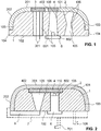
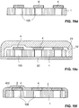
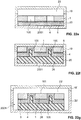
- the FIG. 1 1 shows an embodiment with a base part 1 designed as a carrier part.
- the base part 1 has a front side 101 facing the viewer when the component is installed as intended and a rear side 102 facing away from the front side 101.
- a circumferential lateral end face 103 connects the front side 101 with the rear side 102.
- the transition from the front side 101 to the lateral end face 103 is rounded.
- an edge-side projection 104 extends laterally circumferentially outwards.
- a plurality of apertures 105 are formed, which each extend continuously from the back 102 to the front 101. While in the Fig. 1 arranged on the left-most opening 105 in the cross-sectional view is cylindrical or cylindrical, the two arranged to the right openings 105 are each conical, that is, they each form at least one cone 106. The rightmost aperture 105 even has a biconical shape with two outward on each Koni 106 on.
- a conical configuration of the apertures 105 can on the one hand facilitate the removal of the base part 1 from an injection molding tool and on the other hand facilitate the insertion of, for example, functional elements in the opening 105 or special lighting effects can be achieved.
- the openings of the inventive component may have any shapes as long as they can be produced.
- the mouths of the two in the Fig. 1 The apertures 105 arranged on the left side are each sealingly covered on the front side 101 of the base part 1 with an additional part in the form of a luminous film 3 or a transparent or translucent film 4.
- the luminous film 3 and the film 4 each span a single aperture 105 completely.
- another electrical functional element such as a sensor could be provided.
- Electrical cables 301 are led out from the luminous film 3 through the aperture 105 to the rear side 102 and out of the base part 1.
- a luminous element 6 is arranged such that light emitted therefrom can backlight the foil 4 through the aperture 105.
- a patched on a board 601 LED 602 of the light-emitting element 6 protrudes into the opening 105 into this.
- the front side 101 and part of the lateral end face 103 are covered with a cover layer 2 made of a lacquer.
- the cover layer 2 forms, together with the luminous film 3 and the film 4, a visible side 201 of the component. Due to the cover layer 2, the component may have special optical properties, such as e.g. a high gloss surface, and / or can be made particularly resistant to external influences.
- the cover layer 2 extends circumferentially over the lateral end face 103 to the edge-side projection 104. The surface of the cover layer 2 terminates flush with the outer end face of the edge-side projection 104.
- the surface of the cover layer 2 is arranged in the region of its edge 202 in each case flush with the surfaces of the luminous film 3 and the film 4. Because of these flush arrangements, the component not only gives a higher quality impression, but also dirt deposits are reduced.
- the luminescent film 3 and the film 4 each have the same thickness as the cover layer 2 and are provided on their outer edge 402, i. at their lateral end faces, each circumferentially covered by the cover layer 2.
- Another lighting element can be used to illuminate the far right in the Fig. 1 arranged breakthrough 105 may be provided if the cover layer 2 is made of a transparent or translucent material.
- the cover layer 2 may be made of an opaque material and the base part 1 of a transparent or translucent material. The component would then via the peripheral edge side Led projection 104, which would result in respect to the cover layer 2, a special floating effect.
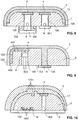
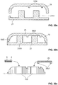
- the embodiment of the FIG. 2 differs from that of the Fig. 1 in that there is a single transparent or translucent foil 4 which completely spans and completely covers all the apertures 105 formed in the base part 1. Furthermore, the film 4 does not form part of the visible side 201 of the component, but the visible side 201 is formed exclusively by the cover layer 2. The film 4 is arranged between the cover layer 2 and the base part 1, wherein it is accommodated in a recess 110 which is formed on the front side 101 of the base part 1.
- a first breakthrough 105 in the Fig. 2 shown component has the shape of a cone '106, which widens towards the film 4.
- a second opening 105 is cylindrical.
- this second breakthrough 105 such a light-emitting element 6 is used, that their LED 602 is located directly below the film 4, otherwise the aperture 105 largely fills.
- the cover layer 2 extends circumferentially over the entire lateral end face 103 of the base part to the rear side 102.
- a luminous film 8 is attached on the back 102 of the base part 1.
- the base part 1 and the cover layer 2 are in the embodiment of Fig. 2 formed transparent or translucent and can be characterized by the luminescent film 8 through or backlit.
- the film 4 may be colored and / or form due to their shape, for example, a symbol or a logo.
- a housing 7 is attached to the back 102 of the base part 1 (in the Fig. 2 shown in dashed lines).
- fastening elements 108 and 701 can be attached to the base part 1 and / or to the housing 7.
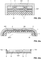
- a luminous element 6 is arranged completely inside an aperture 105.
- the aperture 105 is also filled with a transparent or translucent filler 9, which is the lighting element. 6 completely surrounds and thereby protects.
- the film 4 and the cover layer 2 are preferably each transparent or translucent.
- cover layer 2 can also extend over the rear side 102 of the base part 1.
- FIG. 4 There are several additional parts in the form of films 4, which each cover a cylindrical opening 105 of the base part 1 sealing.
- a cover layer 2 of paint is sprayed, which covers the foils 4 each completely to the visible side and edge.
- a recess is formed, in which a luminescent film 8 is taken, which serves for the backlighting of the films 4 through the apertures 105 therethrough.
- the cover layer 2, but not necessarily the base part 1, is preferably transparent or translucent here.
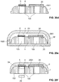
- the base part 1 of the embodiment of FIG. 5 has a single, central aperture 105, which is covered by a transparent, translucent or opaque film 4.
- the film 4 is in turn covered by a transparent or translucent cover layer 15 of lacquer to the visible side and the edge. Outside the cover layer 15, another cover layer 2, which may be opaque, is attached to the base part 1.
- a lighting module is used which serves for the backlighting of the cover layer 15.
- the illumination module can serve for the backlighting of the cover layer 15 directly through the aperture 105, if the film 4 is transparent or translucent. If the film 4 is opaque, the illumination module can also serve for the backlighting of the cover layer 15 through the base part 1, which in this case would be transparent or translucent.
- the lighting module has a housing 7, the interior of which is sealed by means of a sealing foam 13 to the base part 1 and thus to the outside.
- a light guide 10 and one or more lighting elements 6 is arranged, which serve for the irradiation of light into the light guide 10.
- a reflector sheet 12 is arranged in the housing 7, which serves to reflect in the light guide 10 propagating light to the visible side 201 out.
- a further light guide 11 may be provided (in the Fig. 5 shown in dashed lines).
- the interior and / or on the surface of the light guide 10 can also in particular in Be provided at the region of the opening 105 Lichtumsch Weghoff GmbH 1001 to redirect the light to the visible side 201 out and decouple from the light guide 10.
- the light deflection structures can be provided in the interior of the light guide 10 as volume structures or as surface structures in the form of local elevations and depressions on the front or rear side thereof.
- the Lichtumlenk Wegtechnik GmbH are made by means of a laser.
- Correspondingly complementary surface structures may be provided on the light guide 11 and / or on the reflector sheet 12. By the mutual interlocking of the surface structures, in addition, the connection of the light guide 10 to the reflector film 12 and / or the light guide 11 can be improved.
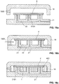
- each additional part available, each covering a breakthrough 105 of the base part 1 sealing and are covered even by the top layer 2 of paint forward and to the sides.
- These two additional parts are each formed as an insert 16 with a projection 1601 and an extension 1602.
- the projection 1601 rests on the front side 101 of the base part 1 and seals the respective aperture 105.
- the extension 1602 extends from the projection 1601 in each case to the rear side 102 of the base part 1 into the respective aperture 105.
- the inserts 16 preferably each form a light guide to direct light from a rear side arranged illumination module to the cover layer 2 made of a transparent or translucent lacquer and to backlight them.
- the insert parts 16 and in particular their extensions 1602 may have scattering elements 1603.
- the lighting module is similar to that of the FIG. 5 educated. In contrast to this, that of the FIG. 6 However, formed on the housing 7 spring hooks 702 which are formed for snapping into snap-in elements 109, which extend from the rear side 102 of the base part 1 to the rear.
- a luminous film 8 is attached to the back of the base part 1, which covers the entire back of the component.
- the luminescent film 8 may in particular be an electroluminescent film or an OLED film.
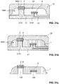
- the in the base part 1 of the Fig. 7 formed apertures 105 each have an opaque formed lining 107 on.
- the foils 4, which cover the apertures 105 may also be opaque in order to prevent passage of light through the apertures 105.
- the light radiated from the luminous film 8 thus passes through the transparent or translucent base part 1 to the cover layer 2.
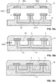
- each two transparent or translucent trained cover layers 2 and 17 are provided from lacquer, wherein the second cover layer 2, the first cover layer 17 completely covered to the visible side.
- the two outer layers 2 and 17 together form a coating consisting of two layers of lacquer.
- the backlighting of the two cover layers 2, 17 takes place by means of luminous elements 6 through in each case one aperture 105.
- the light-emitting elements 6 can each be held in a housing 7, which can be snapped with spring hooks 702 in snap-in elements 109 of the base part 1.
- the breakthroughs 105 formed in the base part 1 are each covered in a sealing manner by means of a transparent or translucent foil 4.
- the front sides of the foils 4 are covered with the lacquer of the cover layer 17 and the lateral end faces of the foils 4 with the material of the base part 1.
- the foil 4 are thereby optimally embedded in the component and seal the apertures 105 in an effective manner towards the cover layer 17 from.
- the additional part which is in contact with the cover layer 2 and which is peripherally covered by the cover layer 2 and / or the base part 1 can also extend from the front side to the lateral edge surface 103 of the base part 1.
- the additional part is formed here in the form of a transparent or translucent film 4, which has in its interior Lichtumlenk Weg Modellen 401 for targeted light deflection.
- the film 4 can thereby be illuminated via an aperture 105 by a luminous element 6 inserted therein in order to decouple light laterally from the component via the edge 202 of the cover layer 2 and thus to irradiate the component.
- the power supply to the light-emitting element 6 serving cable 603 extend through the opening 105 through the back of the component.
- a second in the FIG. 9 shown breakthrough 105 is completely filled with the paint of the cover layer 2.
- a luminous film 8 is on the back side 102 of the base part 1 attached to irradiate light in this breakthrough 105 or in the transparent or translucent paint material and thereby lead to the visible side of the cover layer 2.
- interface structures 1701 are provided in the boundary regions between the base part 1 and a first cover layer 17 made of lacquer and between the first cover layer 17 and a second cover layer 2 made of lacquer.
- the interface structures 1701 are formed by intermeshing local elevations and depressions of the surfaces of the cover layers 2 and 17 and of the base part 1.
- various optical effects can be achieved.
- the interface structures can form symbols or lettering which can be recognized by the observer when the component is backlit.
- the cover layers 2, 17 together form a cover layer made of lacquer with two layers.
- a plastic insert 18 may be inserted into a rear depression of the base part and have local elevations and depressions 1801, which engage in corresponding local elevations and depressions of the base part 1.
- the two laminated layers 2 and 17, which are laminated to one another and made of lacquer, can have different thicknesses D1, D2, D3 and D4 at different points of the component. This is possible in particular by means of production of the cover layers 2 and 17 by injection molding. By means of the different thicknesses a variety of optical effects can be achieved.
- a film 14 may cover part of a luminous film 8 arranged on the back side of the component.
- the same or another film 14 may be reflective and / or colored, in order to generate at the corresponding location a more intense or different-colored light extraction.
- the additional part which in turn is formed here as a film 4, disposed within the base part 1.
- the front and the back of the Film 4, as well as its outer edge 402, are at least partially contacted and in particular covered by the material of the base part 1.
- the opening 105 is optimally sealed by the film 4.
- the film 4 extends through the aperture 105 therethrough. Since the aperture 105 is completely within the area spanned by the film 4, the film 4 completely spans the aperture 105. Since the lacquer of the cover layer 2 extends from the visible side into the aperture 105, the foil 4 is there in contact with the cover layer 2 with its front side.
- the lacquer of the cover layer 2 forms a filling material which at least partially fills the aperture 105.
- FIG. 13 shows schematically the production of the base part 1 of a component according to the invention.
- An injection molding tool is used for this purpose with a first molded part 19 and a second molded part 20 and a molded part insert 21 inserted therein.
- the molded part insert 21 has upwardly projecting projections 2101 for forming the apertures 105 and can also have local elevations and depressions 2102 for forming surface structures have at the base part 1.
- Local elevations and depressions 1902 for forming surface structures on the base part 1 may also be formed on the first mold part 19.
- the surface structures may, for example, form light-deflecting structures 111.
- the molded part insert 21 can in principle also be omitted if the structures 2101 and 2102 are formed directly on the second molded part 20.
- an additional part e.g. arranged in the form of a film 4, which later serves for sealingly covering the openings 105.
- a vacuum line 22 may pass through one or more of the protrusions 2101.
- the foil 4 could also be positioned and releasably held by means of electrostatic forces.
- the injection mold is closed to form an inner cavity 23. Via an injection opening 1905 formed in the first mold part 19, the material of the base part 1 is then injected.
- FIG. 14 is a base part 1 immediately after its production, that is, after removal of the first molding 19, shown. It is readily apparent that the film 4, on the one hand, sealingly covers all apertures 105 and, on the other hand, is completely peripherally covered by the material of the base part 1 at the edge.
- FIG. 15 an embodiment is shown in which the component is produced such that the film 4 covers only a single one of a plurality of apertures 105.
- the film 4 is inserted into a recess 1903 formed on the inside of the first molded part 19. This allows, for example, the production of a component in which the film 4, such as in the Fig. 1 shown forms part of the visible side of the component.
- the film 4 is completely on only one of the projections 2101.
- the film 4 seals in the finished manufactured component only one of the apertures 105.
- the further openings 105 are not completely covered by the film 4.
- the projections 2101 together form a recess with lateral boundaries.
- one of the projections 2101 extends less far from the first mold part 19 than another.
- the film 4 rests on the shorter of these projections 2101, and the first mold part 19 has in the region of the film 4 a downwardly projecting elevation 1904.
- a base part 1 can be produced, in which the film 4 is arranged in a recess formed in the region of the front side 101 and there spans an opening 105 and covers it in a sealing manner.
- the film 4 may be at least partially or as a whole transparent, translucent or opaque or replaced by another accessory, such as a luminescent film, a sensor or another functional element.
- another accessory such as a luminescent film, a sensor or another functional element.
- a film 4 and an additional part in the form of, for example, a sealing plate could be used.
- the additional part can be colored as desired.
- FIGS. 18a to 18g a preferred method for producing a component according to another embodiment of the invention is shown.
- an additional part such as a film 4, placed on projections 2101 of the molding insert 21.
- the projections 2101 which serve to form openings 105 in the base part 1, could in principle also be provided directly on a molded part, ie the one in the Fig. 18a Shaped insert 21 shown could also be a molding.
- the injection molding tool is then closed with a first molded part 19 ( Fig. 18b ), and the material of the base part 1 is injected through an injection port 1905 into a cavity 23 to form the base part 1 ( Fig. 18c ).
- the film 4 is arranged flush with the front of the base part 1.
- the base part 1 is then removed from the injection molding tool ( Fig. 18d ) and in another injection molding tool with a first mold part 19 'and a second mold part 20 used. After closing ( Fig. 18e ), a paint is injected into the cavity 23 through an injection port formed on the first mold part 19 'to flood the base part 1 and the film 4 with the paint and to form a cover layer 2.
- the component is then removed from the injection mold ( Fig. 18f ).
- lighting elements 6 for backlighting the transparent or translucent cover layer 2 through the film 4 can be inserted into the apertures 105.
- sensors 24 may be used in one or more of the openings 105. Control and supply lines in the form of cables 2401 can be led back through the respective aperture 105 through the outside.
- Fig. 19a In a first step, additional parts, for example in the form of foils 4, are placed on one of a plurality of projections 2101 of a molded part insert 21 in each case.
- additional parts for example in the form of foils 4
- the projections 2101 are placed on one of a plurality of projections 2101 of a molded part insert 21 in each case.
- the projections 2101 also recesses 1903 may be provided, in each of which an additional part or a film 4 is used.
- the foils 4 can be held in the depressions 1903, for example, by applying a vacuum.
- the first mold part 19 may have a corresponding vacuum line 1901.
- the injection mold is then, as in the Fig. 19b shown, sealed and the material of the base part 1 via an injection port 1905 injected into the cavity 23.
- the cavity 23 is formed by the first molded part 19 and the molded part insert 21, which could also be a second molded part.
- the base part 1 is formed, which can be removed from the injection molding tool after curing ( FIGS. 19c and 19d ). Due to the projections 2101 have below the films 4 each breakthroughs 105 formed in the base part 1, which are covered by the sheets 4 sealing.
- the base part 1 thus produced with the foils 4 attached thereto is then inserted into a further injection molding tool with a first molded part 19 'and a second molded part 20.
- a paint material is injected into the cavity 23 'formed by this injection molding tool in order to flood the front of the base part 1 with it and to form a cover layer 2 ( Fig. 19e ).
- the foils 4 can rest against the inner surface of the first molded part 19 'with their respective front sides, in order then to form part of the visible side 201 of the component together with the cover layer 2 in the finished component.
- a gap can remain between the foils 4 and the inner surface of the first molded part 19 ', as a result of which the lacquer material flooded the respective foil 4 and the covering layer 2 thus covers the foil 4.
- FIGS. 19e and 19f Both variants are shown. After curing, the component is removed from the injection molding tool ( Fig. 19f ).
- FIGS. 20a to 20c Another preferred method for producing a still further inventive component is shown in the FIGS. 20a to 20c shown.
- the first molded part 19 has elevations 1904 on its inner surface (FIG. Fig. 20a ) which protrude into the cavity 23 ( Fig. 20b ) and for forming depressions on the front side of the base part 1.
- These recesses serve for the secure positioning of an additional part provided with corresponding positioning elements 2501 in the form of a sensor 25 (FIG. Figures 20c and 20d ).
- the sensor 25 is positioned in such a way that it completely spans one of the apertures 105 and seals it in the finished component.
- a second additional part in the form of a film 4 is attached to the base part 1.
- the film 4 is adhered to the front of the base part 1 with the aid of an adhesive and / or a bonding agent 5.
- the film 4 spans, together with the adhesive and / or with the adhesion promoter 5, the opening 105, which after injection molding of the cover layer 2 (FIG. FIGS. 20e and 20f ) allows a very simple attachment of an additional part, for example in the form of a sensor 24, in the corresponding opening 105.
- the sensor 24 can simply be inserted into the opening 105 from the rear side such that it rests against the adhesive and / or the bonding agent 5 (see FIG Fig. 20f ).
- the cover layer 2 here forms the entire visible side of the component and covers both the film 4 as well as the sensor 25 towards the front and laterally completely circumferentially.
- a molded part insert 21 with projections 2101 is used, which extend at different distances into the cavity 23 ( Fig. 21a ).
- the breakthrough 105 spanned underneath by this film 4 thus does not extend completely through the base part 1.
- a second attachment in the form of a film 4 is positioned on another projection 2101.
- This film 4 has already on insertion into the injection molding tool on a cover layer 2 made of a paint.
- This cover layer 2 is completely absorbed by a recess 1903 formed in the first molded part 19.
- the cover layer 2 thereby forms part of the visible side 201 in the finished manufactured component.
- the base part 1 After inserting the base part 1 with attached additional parts and cover layer 2 in another injection mold, the base part 1 is flooded with a lacquer ( Fig. 21d ).
- the lacquer forms a further cover layer 17, the front of which comes to rest flush with the front side of the first cover layer 2.
- the two outer layers 2 and 17 thus together form the visible side 201 of the component ( Fig. 21e ).
- the outer edge 402 of the film 4 covered by the cover layer 2 is completely covered circumferentially by the material of the base part 1.
- the underlying opening 105 is thereby optimally sealed to the cover layers 2 and 17.
- FIGS. 22a to 22h illustrate a further embodiment for producing a component according to the invention.
- a base part 1 is produced here in that a plurality of through openings 105 are formed, for example punched out, therein ( Figures 22a and 22b ).
- an adhesive and / or a bonding agent 5 is then applied ( Fig. 22c ) and then an additional part in the form of a film 4 attached thereto so that it completely spans all apertures 105 ( Fig. 22d ).
- the base part 1 with the film 4 attached thereto is then placed in a cavity 23 formed by two mold parts 19 and 20 ( Fig. 22e ) and back-injected through a provided in the second mold part 20 injection port 2001 therethrough with a plastic.
- the flexible film 4 is pressed into the apertures 105 ( Fig. 22f ).
- Base part 1 and film 4 are pressed against the first mold part 19, resulting in flush transitions of the surface of the film 4 to the surface of the base part 1.
- the injected plastic forms a rear side of the base part 1 and the film 4 arranged plastic layer 26, which may form a support layer in particular. Like from the Fig. 22f it can be seen, engages not only the film 4, but also the plastic layer 26 in the apertures 105 a.
- the as yet unfinished component produced in this way is inserted into a cavity 23 'of a further injection molding tool with a larger dimensioned first molded part 19' and a larger sized second molded part 20 'and flooded with a lacquer ( Fig. 22g ).
- the paint flooded not only the front 101 of the base part 1 and the film 4 in the areas within the apertures 105, but also their lateral end faces and the lateral outer edge of the plastic layer 26.
- the resulting cover layer 2 thus forms the entire visible surface 201 of the finished component both on the front and on the sides ( Fig. 22h ).
- the film 4 is not laterally covered by the cover layer 2, but the outer edge 402 is covered by the plastic layer 26.
- the plastic layer 26 also forms a rear receiving recess 2601, in which the in the Fig. 23b shown lighting module can be used.
- the base part 1 is opaque and the illumination module serves to backlight the transparent or translucent cover layer 2 made of lacquer through the apertures 105.
- the openings 105 can form, for example, symbols, letters or lettering.
- a light guide 10 of the illumination module is used, in which the light is radiated laterally from a luminous element 6.
- each Lichtumlenk Weg 1001 may be provided in or on the light guide 10 there.
- a reflector sheet 12 is attached.
- the lighting module has a preferably opaque formed housing 7, which is fastened by means of adhesive and / or by means of adhesion promoter 703 on the back of the plastic layer 26.
Landscapes
- Engineering & Computer Science (AREA)
- Mechanical Engineering (AREA)
- Chemical & Material Sciences (AREA)
- Combustion & Propulsion (AREA)
- Transportation (AREA)
- Manufacturing & Machinery (AREA)
- Injection Moulding Of Plastics Or The Like (AREA)
- Vehicle Interior And Exterior Ornaments, Soundproofing, And Insulation (AREA)
- Vehicle Waterproofing, Decoration, And Sanitation Devices (AREA)
- Laminated Bodies (AREA)
Priority Applications (3)
| Application Number | Priority Date | Filing Date | Title |
|---|---|---|---|
| EP19187232.4A EP3573043A3 (fr) | 2019-07-19 | 2019-07-19 | Composant comportant une pièce de base, une pièce supplémentaire et une couche de revêtement en laque et procédé de fabrication d'un tel composant |
| PCT/EP2020/069816 WO2021013620A1 (fr) | 2019-07-19 | 2020-07-14 | Élément à partie de base, à partie additionnelle et à couche de recouvrement à base de peinture et procédé de fabrication d'un tel élément |
| EP20739369.5A EP4000058B1 (fr) | 2019-07-19 | 2020-07-14 | Composant comportant une pièce de base, une pièce supplémentaire et une couche de revêtement en laque et procédé de fabrication d'un tel composant |
Applications Claiming Priority (1)
| Application Number | Priority Date | Filing Date | Title |
|---|---|---|---|
| EP19187232.4A EP3573043A3 (fr) | 2019-07-19 | 2019-07-19 | Composant comportant une pièce de base, une pièce supplémentaire et une couche de revêtement en laque et procédé de fabrication d'un tel composant |
Publications (2)
| Publication Number | Publication Date |
|---|---|
| EP3573043A2 true EP3573043A2 (fr) | 2019-11-27 |
| EP3573043A3 EP3573043A3 (fr) | 2019-12-04 |
Family
ID=67438129
Family Applications (2)
| Application Number | Title | Priority Date | Filing Date |
|---|---|---|---|
| EP19187232.4A Withdrawn EP3573043A3 (fr) | 2019-07-19 | 2019-07-19 | Composant comportant une pièce de base, une pièce supplémentaire et une couche de revêtement en laque et procédé de fabrication d'un tel composant |
| EP20739369.5A Active EP4000058B1 (fr) | 2019-07-19 | 2020-07-14 | Composant comportant une pièce de base, une pièce supplémentaire et une couche de revêtement en laque et procédé de fabrication d'un tel composant |
Family Applications After (1)
| Application Number | Title | Priority Date | Filing Date |
|---|---|---|---|
| EP20739369.5A Active EP4000058B1 (fr) | 2019-07-19 | 2020-07-14 | Composant comportant une pièce de base, une pièce supplémentaire et une couche de revêtement en laque et procédé de fabrication d'un tel composant |
Country Status (2)
| Country | Link |
|---|---|
| EP (2) | EP3573043A3 (fr) |
| WO (1) | WO2021013620A1 (fr) |
Cited By (19)
| Publication number | Priority date | Publication date | Assignee | Title |
|---|---|---|---|---|
| DE202020100656U1 (de) * | 2019-12-20 | 2021-03-23 | Rehau Ag + Co | Verkleidungsteil eines Kraftfahrzeuges |
| DE102020110663A1 (de) | 2020-04-20 | 2021-10-21 | Bayerische Motoren Werke Aktiengesellschaft | Anbau- und Zierbauteil für eine Außenseite eines Kraftfahrzeugs und Verfahren |
| WO2021219552A1 (fr) * | 2020-04-30 | 2021-11-04 | Volkswagen Aktiengesellschaft | Panneau de garniture intérieure pour un véhicule automobile |
| WO2022008324A1 (fr) | 2020-07-10 | 2022-01-13 | Preh Gmbh | Partie visible ayant une structure de couche pour une pièce d'actionnement ou une garniture décorative avec une meilleure protection à la suite d'un revêtement de peinture de protection |
| DE102020117815A1 (de) | 2020-07-07 | 2022-01-13 | Dr. Schneider Kunststoffwerke Gmbh | Formteil mit einer durchleuchtbaren Oberflächenschicht und Verfahren zum Herstellen eines Formteils mit einer durchleuchtbaren Oberflächenschicht |
| WO2023281064A1 (fr) * | 2021-07-08 | 2023-01-12 | Novem Car Interior Design Gmbh | Pièce moulée et procédé de production correspondant |
| DE102021117786A1 (de) | 2021-07-09 | 2023-01-12 | Bayerische Motoren Werke Aktiengesellschaft | Durchleuchtbares Verkleidungsbauteil für ein Interieur eines Kraftfahrzeugs, Interieurbauteil und Kraftfahrzeug |
| DE102021119432A1 (de) | 2021-07-27 | 2023-02-02 | Bayerische Motoren Werke Aktiengesellschaft | Anbau- oder Zierbauteil für ein Kraftfahrzeug, Kraftfahrzeug mit einem Anbau- oder Zierbauteil und Verfahren zur Herstellung eines Anbau- oder Zierbauteils |
| DE202021106938U1 (de) | 2021-12-21 | 2023-03-22 | Rehau Automotive Se & Co. Kg | Außenverkleidungsteil für ein Kraftfahrzeug |
| DE102022107875B3 (de) | 2022-04-01 | 2023-10-05 | Dr. Ing. H.C. F. Porsche Aktiengesellschaft | Schutzeinrichtung und Montageverfahren |
| DE102022208338A1 (de) * | 2022-08-10 | 2024-02-15 | Faurecia Innenraum Systeme Gmbh | Fahrzeuginnenverkleidungsteil und Verfahren zum Herstellen des Fahrzeuginnenverkleidungsteils |
| DE102023000982A1 (de) | 2023-03-13 | 2024-02-22 | Mercedes-Benz Group AG | Verkleidungsteil für ein Kraftfahrzeug und Kraftfahrzeug mit einem solchen Verkleidungsteil |
| DE102022122586A1 (de) | 2022-09-06 | 2024-03-07 | Audi Aktiengesellschaft | Dekor- oder Verkleidungsbauteil für ein Land- oder Luftfahrzeug |
| DE102022003970A1 (de) * | 2022-10-25 | 2024-04-25 | Mercedes-Benz Group AG | Beleuchtetes Exterieur Zierelement mit Chromoptik |
| DE102023000269A1 (de) | 2023-01-30 | 2024-08-01 | Mercedes-Benz Group AG | Beleuchtbarer Dekormehrschichtverbund, Anbauteil für ein Fahrzeug sowie Fahrzeug |
| WO2024179734A1 (fr) * | 2023-02-28 | 2024-09-06 | Mercedes-Benz Group AG | Dispositif d'éclairage pour un véhicule et composant de véhicule le comprenant |
| US12173890B2 (en) | 2021-07-08 | 2024-12-24 | Novem Car Interior Design Gmbh | Shaped part and method for producing a shaped part |
| WO2025012083A1 (fr) | 2023-07-10 | 2025-01-16 | BHTC GmbH | Couvercle pour un boîtier, en particulier pour un composant de l'habitacle d'un véhicule et procédé de production d'un tel couvercle |
| DE102023206982A1 (de) * | 2023-07-21 | 2025-01-23 | Faurecia Innenraum Systeme Gmbh | Fahrzeugverkleidungsteil mit leuchtfunktion |
Families Citing this family (7)
| Publication number | Priority date | Publication date | Assignee | Title |
|---|---|---|---|---|
| US11904768B2 (en) * | 2022-03-14 | 2024-02-20 | Caterpillar Inc. | Cabin light and cabin light assembly for machine |
| DE102022120905A1 (de) * | 2022-08-18 | 2024-02-29 | Bayerische Motoren Werke Aktiengesellschaft | Gehäuse für einen Fahrzeugscheinwerfer, Fahrzeugscheinwerfer und ein Fahrzeug |
| DE102023104893A1 (de) * | 2023-02-28 | 2024-08-29 | Tts Tooltechnic Systems Ag & Co. Kg | Kantenumleimer |
| DE102023210913A1 (de) * | 2023-11-03 | 2025-05-08 | Robert Bosch Gesellschaft mit beschränkter Haftung | Mikrofluidische Vorrichtung und Verfahren zu deren Herstellung |
| DE102024115476A1 (de) * | 2024-06-04 | 2025-12-04 | Ams-Osram International Gmbh | Leuchtvorrichtung und verfahren zur herstellung einer leuchtvorrichtung |
| DE102024121355A1 (de) * | 2024-07-26 | 2026-01-29 | Lisa Dräxlmaier GmbH | Dekorelement für einen innenraum eines fahrzeugs, und herstellungsverfahren |
| EP4696927A1 (fr) | 2024-08-12 | 2026-02-18 | WEIDPLAS GmbH | Composant de véhicule automobile |
Citations (5)
| Publication number | Priority date | Publication date | Assignee | Title |
|---|---|---|---|---|
| DE102009004985A1 (de) | 2009-01-14 | 2010-07-22 | Sellner Gmbh | Verkleidungsteil mit Sensor |
| DE102010017494A1 (de) | 2010-06-21 | 2011-12-22 | Novem Car Interior Design Gmbh | Formteil mit Lichtleitern zur Symboldarstellung und Verfahren zu seiner Herstellung |
| WO2016193384A1 (fr) | 2015-06-03 | 2016-12-08 | Weidplas Gmbh | Pièce |
| EP2684744B1 (fr) | 2012-07-09 | 2018-05-02 | Wiegand GmbH | Pièce décorative pour véhicules automobiles ainsi que son procédé de fabrication |
| WO2018104045A1 (fr) | 2016-12-09 | 2018-06-14 | Weidplas Gmbh | Pièce présentant une couche de recouvrement et procédé de fabrication d'une telle pièce |
Family Cites Families (6)
| Publication number | Priority date | Publication date | Assignee | Title |
|---|---|---|---|---|
| FR2917350B1 (fr) * | 2007-06-13 | 2009-12-18 | Faurecia Interieur Ind | Structure interieure de vehicule automobile comportant un affichage sous peau et procede de fabrication d'une telle structure. |
| FR2920119B1 (fr) * | 2007-08-23 | 2010-02-26 | Faurecia Interieur Ind | Panneau de garnissage souple de vehicule automobile comprenant un pictogramme retroeclaire |
| FR2935325B1 (fr) * | 2008-08-29 | 2010-09-24 | Faurecia Interieur Ind | Panneau de garnissage de vehicule automobile comprenant une zone formant pictogramme anti-reflet et vehicule automobile associe |
| DE202015100322U1 (de) * | 2015-01-23 | 2016-02-02 | Novem Car Interior Design Gmbh | Formteil, insbesondere als Formteil ausgebildetes Dekorteil und/oder Verkleidungsteil für einen Fahrzeuginnenraum |
| KR101866849B1 (ko) * | 2018-03-09 | 2018-06-14 | 주식회사 서연이화 | 스위치 조립용 차량 도어의 소프트 어퍼 트림 및 그 양산공법 |
| KR101861189B1 (ko) * | 2018-03-09 | 2018-06-29 | 주식회사 서연이화 | 스위치 조립용 차량 도어의 소프트 어퍼 트림 및 그 양산공법 |
-
2019
- 2019-07-19 EP EP19187232.4A patent/EP3573043A3/fr not_active Withdrawn
-
2020
- 2020-07-14 WO PCT/EP2020/069816 patent/WO2021013620A1/fr not_active Ceased
- 2020-07-14 EP EP20739369.5A patent/EP4000058B1/fr active Active
Patent Citations (5)
| Publication number | Priority date | Publication date | Assignee | Title |
|---|---|---|---|---|
| DE102009004985A1 (de) | 2009-01-14 | 2010-07-22 | Sellner Gmbh | Verkleidungsteil mit Sensor |
| DE102010017494A1 (de) | 2010-06-21 | 2011-12-22 | Novem Car Interior Design Gmbh | Formteil mit Lichtleitern zur Symboldarstellung und Verfahren zu seiner Herstellung |
| EP2684744B1 (fr) | 2012-07-09 | 2018-05-02 | Wiegand GmbH | Pièce décorative pour véhicules automobiles ainsi que son procédé de fabrication |
| WO2016193384A1 (fr) | 2015-06-03 | 2016-12-08 | Weidplas Gmbh | Pièce |
| WO2018104045A1 (fr) | 2016-12-09 | 2018-06-14 | Weidplas Gmbh | Pièce présentant une couche de recouvrement et procédé de fabrication d'une telle pièce |
Cited By (31)
| Publication number | Priority date | Publication date | Assignee | Title |
|---|---|---|---|---|
| DE202020100656U1 (de) * | 2019-12-20 | 2021-03-23 | Rehau Ag + Co | Verkleidungsteil eines Kraftfahrzeuges |
| DE102020110663A1 (de) | 2020-04-20 | 2021-10-21 | Bayerische Motoren Werke Aktiengesellschaft | Anbau- und Zierbauteil für eine Außenseite eines Kraftfahrzeugs und Verfahren |
| WO2021219552A1 (fr) * | 2020-04-30 | 2021-11-04 | Volkswagen Aktiengesellschaft | Panneau de garniture intérieure pour un véhicule automobile |
| DE102020205520A1 (de) | 2020-04-30 | 2021-11-04 | Volkswagen Aktiengesellschaft | Innenverkleidungsteil für ein Kraftfahrzeug |
| CN115427260B (zh) * | 2020-04-30 | 2025-10-17 | 大众汽车股份公司 | 用于机动车的内部装饰部件 |
| CN115427260A (zh) * | 2020-04-30 | 2022-12-02 | 大众汽车股份公司 | 用于机动车的内部装饰部件 |
| CN115916514A (zh) * | 2020-07-07 | 2023-04-04 | 施耐德博士塑料工厂有限公司 | 具有可透射的表面层的成型件以及用于制造具有可透射的表面层的成型件的方法 |
| DE102020117815A1 (de) | 2020-07-07 | 2022-01-13 | Dr. Schneider Kunststoffwerke Gmbh | Formteil mit einer durchleuchtbaren Oberflächenschicht und Verfahren zum Herstellen eines Formteils mit einer durchleuchtbaren Oberflächenschicht |
| WO2022008389A1 (fr) | 2020-07-07 | 2022-01-13 | Dr. Schneider Kunststoffwerke Gmbh | Élément moulé comportant une couche de surface translucide et procédé de fabrication d'un élément moulé comportant une couche de surface translucide |
| US20230294341A1 (en) * | 2020-07-07 | 2023-09-21 | Dr. Schneider Kunststoffwerke Gmbh I. Ins. | Molding having a translucent surface layer and method for producing a molding having a translucent surface layer |
| US20230182452A1 (en) * | 2020-07-10 | 2023-06-15 | Preh Gmbh | A visible part having a layer structure for an operating part or a decorative trim with better protection as a result of a protective paint coating |
| DE102020121563A1 (de) | 2020-07-10 | 2022-01-13 | Preh Gmbh | Einen Schichtaufbau aufweisendes Sichtteil für ein Bedienteil oder eine Zierblende mit verbessertem Schutz durch eine Schutzlackbeschichtung |
| WO2022008324A1 (fr) | 2020-07-10 | 2022-01-13 | Preh Gmbh | Partie visible ayant une structure de couche pour une pièce d'actionnement ou une garniture décorative avec une meilleure protection à la suite d'un revêtement de peinture de protection |
| US12496812B2 (en) * | 2020-07-10 | 2025-12-16 | Preh Gmbh | Visible part having a layer structure for an operating part or a decorative trim with better protection as a result of a protective paint coating |
| WO2023281064A1 (fr) * | 2021-07-08 | 2023-01-12 | Novem Car Interior Design Gmbh | Pièce moulée et procédé de production correspondant |
| US12173890B2 (en) | 2021-07-08 | 2024-12-24 | Novem Car Interior Design Gmbh | Shaped part and method for producing a shaped part |
| US12472817B2 (en) | 2021-07-08 | 2025-11-18 | Novem Car Interior Design Gmbh | Shaped part and method for producing a shaped part |
| DE102021117786A1 (de) | 2021-07-09 | 2023-01-12 | Bayerische Motoren Werke Aktiengesellschaft | Durchleuchtbares Verkleidungsbauteil für ein Interieur eines Kraftfahrzeugs, Interieurbauteil und Kraftfahrzeug |
| DE102021119432A1 (de) | 2021-07-27 | 2023-02-02 | Bayerische Motoren Werke Aktiengesellschaft | Anbau- oder Zierbauteil für ein Kraftfahrzeug, Kraftfahrzeug mit einem Anbau- oder Zierbauteil und Verfahren zur Herstellung eines Anbau- oder Zierbauteils |
| DE202021106938U1 (de) | 2021-12-21 | 2023-03-22 | Rehau Automotive Se & Co. Kg | Außenverkleidungsteil für ein Kraftfahrzeug |
| EP4201753A1 (fr) * | 2021-12-21 | 2023-06-28 | REHAU Automotive SE & Co. KG | Pièce d'habillage extérieure pour un véhicule automobile |
| DE102022107875B3 (de) | 2022-04-01 | 2023-10-05 | Dr. Ing. H.C. F. Porsche Aktiengesellschaft | Schutzeinrichtung und Montageverfahren |
| DE102022208338A1 (de) * | 2022-08-10 | 2024-02-15 | Faurecia Innenraum Systeme Gmbh | Fahrzeuginnenverkleidungsteil und Verfahren zum Herstellen des Fahrzeuginnenverkleidungsteils |
| DE102022122586A1 (de) | 2022-09-06 | 2024-03-07 | Audi Aktiengesellschaft | Dekor- oder Verkleidungsbauteil für ein Land- oder Luftfahrzeug |
| DE102022003970A1 (de) * | 2022-10-25 | 2024-04-25 | Mercedes-Benz Group AG | Beleuchtetes Exterieur Zierelement mit Chromoptik |
| DE102023000269A1 (de) | 2023-01-30 | 2024-08-01 | Mercedes-Benz Group AG | Beleuchtbarer Dekormehrschichtverbund, Anbauteil für ein Fahrzeug sowie Fahrzeug |
| WO2024179734A1 (fr) * | 2023-02-28 | 2024-09-06 | Mercedes-Benz Group AG | Dispositif d'éclairage pour un véhicule et composant de véhicule le comprenant |
| DE102023000982A1 (de) | 2023-03-13 | 2024-02-22 | Mercedes-Benz Group AG | Verkleidungsteil für ein Kraftfahrzeug und Kraftfahrzeug mit einem solchen Verkleidungsteil |
| WO2025012083A1 (fr) | 2023-07-10 | 2025-01-16 | BHTC GmbH | Couvercle pour un boîtier, en particulier pour un composant de l'habitacle d'un véhicule et procédé de production d'un tel couvercle |
| DE102023206982A1 (de) * | 2023-07-21 | 2025-01-23 | Faurecia Innenraum Systeme Gmbh | Fahrzeugverkleidungsteil mit leuchtfunktion |
| US12472867B2 (en) | 2023-07-21 | 2025-11-18 | HELLA GmbH & Co. KGaA | Vehicle trim part with lighting function |
Also Published As
| Publication number | Publication date |
|---|---|
| EP3573043A3 (fr) | 2019-12-04 |
| WO2021013620A1 (fr) | 2021-01-28 |
| EP4000058A1 (fr) | 2022-05-25 |
| EP4000058B1 (fr) | 2025-03-26 |
Similar Documents
| Publication | Publication Date | Title |
|---|---|---|
| EP4000058B1 (fr) | Composant comportant une pièce de base, une pièce supplémentaire et une couche de revêtement en laque et procédé de fabrication d'un tel composant | |
| EP3976423B1 (fr) | Composant pouvant être rétro-éclairé | |
| EP2684744B1 (fr) | Pièce décorative pour véhicules automobiles ainsi que son procédé de fabrication | |
| EP2596991B1 (fr) | Pièce comportant un éclairage | |
| DE102014112470B4 (de) | Ausstattungsteil mit leuchtender sichtseite | |
| EP3048015B1 (fr) | Piece de formage, en particulier piece decorative et/ou piece d'habillage conçue comme une piece de formage pour l'espace interieur d'un vehicule et procede de fabrication de piece de formage | |
| EP3150442B1 (fr) | Pièce décorative de véhicule | |
| EP2178719B1 (fr) | Élément arrière pour un véhicule automobile comportant une unité d'éclairage | |
| EP3233491B1 (fr) | Procédé de fabrication d'un composant de véhicule en matière synthétique | |
| EP3999303A1 (fr) | Élément à partie porteuse et à couche de recouvrement et procédé de fabrication d'un tel élément | |
| EP3572282A1 (fr) | Élément ornemental pouvant être éclairé par derrière pour un véhicule | |
| DE202016100258U1 (de) | Formteil, insbesondere als Formteil ausgebildetes Dekorteil und/oder Verkleidungsteil für einen Fahrzeuginnenraum | |
| DE102012110153A1 (de) | Formteil und Verfahren zur Herstellung dieses Formteils | |
| DE112020005121T5 (de) | Beleuchtete anzeigetafel und verfahren zur herstellung derselben | |
| DE102015003207A1 (de) | Ziervorrichtung für ein Kraftfahrzeug | |
| DE102021100532A1 (de) | Dekorteil | |
| DE102007057934A1 (de) | Verfahren zum Herstellen eines auf zumindest einer Fläche kunststoffbeschichteten metallischen Bauteils | |
| EP4344949B1 (fr) | Système d'éclairage pour un élément d'habillage extérieur d'un véhicule automobile | |
| DE102007029716A1 (de) | Kunststoffaufbauteil für ein Fahrzeug und Verfahren zu dessen Herstellung | |
| EP4271555A1 (fr) | Élément moulé comportant une couche de surface translucide et procédé de fabrication d'un élément moulé comportant une couche de surface translucide | |
| DE102011006034A1 (de) | Verfahren zur Herstellung eines Verbundbauteils | |
| EP2815865B1 (fr) | Procédé de fabrication d'un composant composite en matière plastique | |
| EP3722065A9 (fr) | Pièce de garniture de véhicule automobile et son procédé de fabrication | |
| DE102015006395B4 (de) | Verfahren zum Herstellen eines Bauteils für ein Kraftfahrzeug, Bauteil und Kraftfahrzeug |
Legal Events
| Date | Code | Title | Description |
|---|---|---|---|
| PUAI | Public reference made under article 153(3) epc to a published international application that has entered the european phase |
Free format text: ORIGINAL CODE: 0009012 |
|
| STAA | Information on the status of an ep patent application or granted ep patent |
Free format text: STATUS: THE APPLICATION HAS BEEN PUBLISHED |
|
| PUAL | Search report despatched |
Free format text: ORIGINAL CODE: 0009013 |
|
| AK | Designated contracting states |
Kind code of ref document: A2 Designated state(s): AL AT BE BG CH CY CZ DE DK EE ES FI FR GB GR HR HU IE IS IT LI LT LU LV MC MK MT NL NO PL PT RO RS SE SI SK SM TR |
|
| AX | Request for extension of the european patent |
Extension state: BA ME |
|
| AK | Designated contracting states |
Kind code of ref document: A3 Designated state(s): AL AT BE BG CH CY CZ DE DK EE ES FI FR GB GR HR HU IE IS IT LI LT LU LV MC MK MT NL NO PL PT RO RS SE SI SK SM TR |
|
| AX | Request for extension of the european patent |
Extension state: BA ME |
|
| RIC1 | Information provided on ipc code assigned before grant |
Ipc: B60Q 3/54 20170101ALI20191025BHEP Ipc: B29C 45/17 20060101ALI20191025BHEP Ipc: B60R 13/04 20060101ALI20191025BHEP Ipc: B60Q 3/14 20170101ALI20191025BHEP Ipc: G09F 13/00 20060101AFI20191025BHEP Ipc: B60R 13/02 20060101ALI20191025BHEP Ipc: B29C 45/16 20060101ALI20191025BHEP |
|
| STAA | Information on the status of an ep patent application or granted ep patent |
Free format text: STATUS: THE APPLICATION IS DEEMED TO BE WITHDRAWN |
|
| 18D | Application deemed to be withdrawn |
Effective date: 20200605 |