EP3576687B1 - Verfahren und vorrichtung zur unterstützung und stabilisierung eines patienten bei der hüftdistraktion - Google Patents
Verfahren und vorrichtung zur unterstützung und stabilisierung eines patienten bei der hüftdistraktion Download PDFInfo
- Publication number
- EP3576687B1 EP3576687B1 EP18747256.8A EP18747256A EP3576687B1 EP 3576687 B1 EP3576687 B1 EP 3576687B1 EP 18747256 A EP18747256 A EP 18747256A EP 3576687 B1 EP3576687 B1 EP 3576687B1
- Authority
- EP
- European Patent Office
- Prior art keywords
- patient
- extender
- table extender
- surgical
- stabilizing pad
- Prior art date
- Legal status (The legal status is an assumption and is not a legal conclusion. Google has not performed a legal analysis and makes no representation as to the accuracy of the status listed.)
- Active
Links
Images


Classifications
-
- A—HUMAN NECESSITIES
- A61—MEDICAL OR VETERINARY SCIENCE; HYGIENE
- A61G—TRANSPORT, PERSONAL CONVEYANCES, OR ACCOMMODATION SPECIALLY ADAPTED FOR PATIENTS OR DISABLED PERSONS; OPERATING TABLES OR CHAIRS; CHAIRS FOR DENTISTRY; FUNERAL DEVICES
- A61G13/00—Operating tables; Auxiliary appliances therefor
- A61G13/10—Parts, details or accessories
- A61G13/12—Rests specially adapted therefor; Arrangements of patient-supporting surfaces
- A61G13/128—Rests specially adapted therefor; Arrangements of patient-supporting surfaces with mechanical surface adaptations
- A61G13/1285—Rests specially adapted therefor; Arrangements of patient-supporting surfaces with mechanical surface adaptations having modular surface parts, e.g. being replaceable or turnable
-
- A—HUMAN NECESSITIES
- A61—MEDICAL OR VETERINARY SCIENCE; HYGIENE
- A61B—DIAGNOSIS; SURGERY; IDENTIFICATION
- A61B17/00—Surgical instruments, devices or methods
- A61B17/02—Surgical instruments, devices or methods for holding wounds open, e.g. retractors; Tractors
- A61B17/025—Joint distractors
-
- A—HUMAN NECESSITIES
- A61—MEDICAL OR VETERINARY SCIENCE; HYGIENE
- A61G—TRANSPORT, PERSONAL CONVEYANCES, OR ACCOMMODATION SPECIALLY ADAPTED FOR PATIENTS OR DISABLED PERSONS; OPERATING TABLES OR CHAIRS; CHAIRS FOR DENTISTRY; FUNERAL DEVICES
- A61G13/00—Operating tables; Auxiliary appliances therefor
- A61G13/0036—Orthopaedic operating tables
- A61G13/0081—Orthopaedic operating tables specially adapted for hip surgeries
-
- A—HUMAN NECESSITIES
- A61—MEDICAL OR VETERINARY SCIENCE; HYGIENE
- A61G—TRANSPORT, PERSONAL CONVEYANCES, OR ACCOMMODATION SPECIALLY ADAPTED FOR PATIENTS OR DISABLED PERSONS; OPERATING TABLES OR CHAIRS; CHAIRS FOR DENTISTRY; FUNERAL DEVICES
- A61G13/00—Operating tables; Auxiliary appliances therefor
- A61G13/10—Parts, details or accessories
- A61G13/12—Rests specially adapted therefor; Arrangements of patient-supporting surfaces
- A61G13/1205—Rests specially adapted therefor; Arrangements of patient-supporting surfaces for specific parts of the body
- A61G13/1245—Knees, upper or lower legs
-
- A—HUMAN NECESSITIES
- A61—MEDICAL OR VETERINARY SCIENCE; HYGIENE
- A61G—TRANSPORT, PERSONAL CONVEYANCES, OR ACCOMMODATION SPECIALLY ADAPTED FOR PATIENTS OR DISABLED PERSONS; OPERATING TABLES OR CHAIRS; CHAIRS FOR DENTISTRY; FUNERAL DEVICES
- A61G13/00—Operating tables; Auxiliary appliances therefor
- A61G13/10—Parts, details or accessories
- A61G13/12—Rests specially adapted therefor; Arrangements of patient-supporting surfaces
- A61G13/126—Rests specially adapted therefor; Arrangements of patient-supporting surfaces with specific supporting surface
-
- A—HUMAN NECESSITIES
- A61—MEDICAL OR VETERINARY SCIENCE; HYGIENE
- A61B—DIAGNOSIS; SURGERY; IDENTIFICATION
- A61B17/00—Surgical instruments, devices or methods
- A61B17/56—Surgical instruments or methods for treatment of bones or joints; Devices specially adapted therefor
- A61B17/58—Surgical instruments or methods for treatment of bones or joints; Devices specially adapted therefor for osteosynthesis, e.g. bone plates, screws or setting implements
- A61B17/60—Surgical instruments or methods for treatment of bones or joints; Devices specially adapted therefor for osteosynthesis, e.g. bone plates, screws or setting implements for external osteosynthesis, e.g. distractors, contractors
- A61B17/66—Alignment, compression or distraction mechanisms
-
- A—HUMAN NECESSITIES
- A61—MEDICAL OR VETERINARY SCIENCE; HYGIENE
- A61B—DIAGNOSIS; SURGERY; IDENTIFICATION
- A61B17/00—Surgical instruments, devices or methods
- A61B17/02—Surgical instruments, devices or methods for holding wounds open, e.g. retractors; Tractors
- A61B17/025—Joint distractors
- A61B2017/0268—Joint distractors for the knee
-
- A—HUMAN NECESSITIES
- A61—MEDICAL OR VETERINARY SCIENCE; HYGIENE
- A61B—DIAGNOSIS; SURGERY; IDENTIFICATION
- A61B17/00—Surgical instruments, devices or methods
- A61B17/02—Surgical instruments, devices or methods for holding wounds open, e.g. retractors; Tractors
- A61B17/025—Joint distractors
- A61B2017/0275—Joint distractors for the hip
-
- A—HUMAN NECESSITIES
- A61—MEDICAL OR VETERINARY SCIENCE; HYGIENE
- A61F—FILTERS IMPLANTABLE INTO BLOOD VESSELS; PROSTHESES; DEVICES PROVIDING PATENCY TO, OR PREVENTING COLLAPSING OF, TUBULAR STRUCTURES OF THE BODY, e.g. STENTS; ORTHOPAEDIC, NURSING OR CONTRACEPTIVE DEVICES; FOMENTATION; TREATMENT OR PROTECTION OF EYES OR EARS; BANDAGES, DRESSINGS OR ABSORBENT PADS; FIRST-AID KITS
- A61F5/00—Orthopaedic methods or devices for non-surgical treatment of bones or joints; Nursing devices ; Anti-rape devices
- A61F5/37—Restraining devices for the body or for body parts; Restraining shirts
-
- A—HUMAN NECESSITIES
- A61—MEDICAL OR VETERINARY SCIENCE; HYGIENE
- A61G—TRANSPORT, PERSONAL CONVEYANCES, OR ACCOMMODATION SPECIALLY ADAPTED FOR PATIENTS OR DISABLED PERSONS; OPERATING TABLES OR CHAIRS; CHAIRS FOR DENTISTRY; FUNERAL DEVICES
- A61G2203/00—General characteristics of devices
- A61G2203/30—General characteristics of devices characterised by sensor means
- A61G2203/42—General characteristics of devices characterised by sensor means for inclination
Definitions
- This invention relates to medical apparatus in general, and more particularly to medical apparatus for supporting and stabilizing a patient during hip distraction.
- a padded post between the legs of the patient.
- This padded post provides a counterforce to the anatomy when the distraction force is applied to the surgical boot.
- the use of a padded post can create complications, since the padded post can press against the pudendal nerve of the patient, and/or the sciatic nerve of the patient, during distraction. Additionally, the padded post can exert pressure on the blood vessels in the leg of the patient during distraction. Thus, it would be desirable to minimize or eliminate the use of the padded post if other means could be used to provide a counterforce to the anatomy when the distraction force is applied to the surgical boot.
- Trendelenburg position e.g., during abdominal surgery.
- the patient lies on the surgical table "flat on their back", with their feet higher than their head, e.g., by approximately 15-30 degrees.
- the surgical table is typically tilted so that the patient's head is angled downward and the patient's feet are angled upward.
- post-less hip distraction Another benefit of post-less hip distraction is that the non-operative leg remains relaxed while the operative leg is being "pulled on” for distraction. This is because gravity and the friction associated with the tilted surgical table are being used to keep the patient stable on the surgical table, not a post mounted to the surgical table.
- a post acts as a point of counter-traction; as such, the hip pivots around the post, resulting in a transfer of force to the non-operative leg. Without a post, there is no fulcrum and hence no force is transferred to the non-operative leg. This can benefit the patient inasmuch as any possible risks associated with forces being applied to the non-operative leg (such as neurovascular damage) are eliminated.
- the post may be removed when traction is not required, such as while work is being done in the peripheral compartment of the hip.
- traction is not required
- there are times when it may be necessary to re-introduce the post such as when traction is needed to check on work done in the central compartment, or when a bilateral procedure is performed and traction is needed for the other hip.
- the patient When the patient is disposed in the Trendelenburg position, gravity acts to pull the patient downward, towards their head, and the body of the patient could slide on the surgical table. Additionally, during post-less hip distraction, the patient could slide on the surgical table when force is applied to the patient's leg in order to effect the hip distraction. For example, the patient could slide distally (i.e., towards their feet) as the leg is pulled distally by the distraction frame. The patient could also slide or roll laterally towards the side edge of the surgical table, e.g., this could be the result of the leg being abducted when the pulling force is applied to the distal end of the leg, thereby generating a lateral force in addition to the distal force. Such unintended movement of the patient's body can disrupt the surgical procedure and/or cause tissue damage. In extreme cases, the patient could even fall off of the surgical table.
- the present invention is intended to provide new and improved approaches for supporting and stabilizing a patient during hip distraction, both with and without a post. Such approaches are intended to provide improved hip distraction, facilitate post-less hip distraction, minimize pressure on a patient if a post is used, and prevent a patient from sliding or rolling on the surgical table during hip distraction.
- the present invention provides new and improved approaches for transferring, supporting and stabilizing a patient during hip distraction.
- Such approaches are intended to provide improved hip distraction, facilitate post-less hip distraction, minimize pressure on a patient if a post is used, and prevent a patient from sliding or rolling on the surgical table during hip distraction.
- the present invention comprises the provision and use of a novel system for transferring, supporting and stabilizing a patient during hip distraction.
- the invention provides a table extender as defined in the appended claims, configured to be connected to a surgical table having side rails extending along the sides of a platform of the surgical table and being spaced from the platform on rail mounts, the table extender comprising:
- the present invention provides new and improved approaches for transferring, supporting and stabilizing a patient during hip distraction.
- Such approaches are intended to provide improved hip distraction, facilitate post-less hip distraction, minimize pressure on a patient if a post is used, and prevent a patient from sliding or rolling on the surgical table during hip distraction.
- the present invention comprises the provision and use of a novel system for transferring, supporting and stabilizing a patient during hip distraction.
- Novel system 5 for transferring, supporting and stabilizing a patient during hip distraction.
- Novel system 5 is intended to provide improved hip distraction, facilitate post-less hip distraction, minimize pressure on a patient if a post is used, and prevent a patient from sliding or rolling on the surgical table during hip distraction.
- Novel system 5 generally comprises a table extender 10 for mounting to one end of a surgical table 15, a stabilizing pad 20 for positioning on surgical table 15 and table extender 10 so that the patient resides on stabilizing pad 20, and a patient strap 22 for securing the patient to surgical table 15.
- surgical table 15 is generally formed out of a radiopaque material, e.g., metal.
- a radiopaque material e.g., metal.
- table extender 10 for mounting to one end of surgical table 15.
- table extender 10 is constructed so that patient anatomy supported on table extender 10 can be imaged with X-ray technology through the table extender, thereby enabling CT imaging and X-ray imaging with substantially unlimited angles of view.
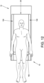
- table extender 10 is sized to support the patient from a point proximal to the hips of the patient to a point proximal to the knees of the patient, whereby to provide optimal support for hip distraction, particularly when the patient is positioned in the so-called "Trendelenburg position" during hip surgery.
- Table extender 10 also provides increased flexibility in the ability to X-ray the hip joint from multiple viewpoints while the hip joint is supported on table extender 10.
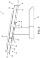
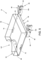
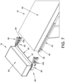
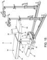
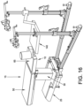
- table extender 10 comprises a distal end 53 and a proximal end 54. More particularly, table extender 10 comprises a base 55 having a distal end 56 and a proximal end 57, a pair of mounts 60 for mounting base 55 to side rails 40 of surgical table 15, and a cushion 65 for disposition on base 55.
- Base 55 preferably comprises a substantially rigid radiolucent material (e.g., a carbon fiber composite) such that X-ray and/or CT imaging may be performed on the anatomy residing on table extender 10, and base 55 is sufficiently strong to support a substantial portion of the patient's weight. See, for example, Fig. 9 , which shows a C-arm X-ray machine 70 disposed about table extender 10 so that C-arm X-ray machine 70 can image anatomy supported on table extender 10.
- a substantially rigid radiolucent material e.g., a carbon fiber composite
- Base 55 of table extender 10 may comprise one or more openings, e.g., side openings 75 for enabling easy grasping of table extender 10 during mounting to, and dismounting from, surgical table 15, and/or for receiving straps of stabilizing pad 20 (see below), distal openings 80 for enabling other equipment to be mounted to table extender 10 (e.g., a post), etc.
- openings e.g., side openings 75 for enabling easy grasping of table extender 10 during mounting to, and dismounting from, surgical table 15, and/or for receiving straps of stabilizing pad 20 (see below), distal openings 80 for enabling other equipment to be mounted to table extender 10 (e.g., a post), etc.
- Mounts 60 may be substantially any mounts which allow base 55 to be attached to, or detached from, surgical table 15 without significantly diminishing the overall radiolucency of table extender 10.
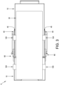
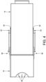
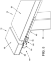
- each of the mounts 60 generally comprises a body 85 mounted to proximal end 57 of base 55 and extending proximally therefrom.
- Bodies 85 comprise slots 90 for receiving side rails 40 of surgical table 15.
- Clamps 95 are pivotally mounted to bodies 85, such that clamps 95 can be pivoted towards and away from bodies 85.
- Clamps 95 preferably comprise recesses 100 for disposition about mounts 45 of side rails 40 when side rails 40 are received in slots 90.
- mounts 60 comprise friction elements (not shown) which prevent clamps 95 from falling into their locked position until after the user deliberately pushes clamps 95 into their locked position.
- these friction elements comprise spring plungers which are adjusted so as to provide a degree of resistance to clamps 95 closing into their locked position.
- other sources of friction or resistance can be utilized such as interference fits between the machined components, ramps, springs, or additional materials such as rubber or silicone added to increase the friction locally.
- Locking screws 105 extend through bodies 85 and project into slots 90, whereby to enable mounts 60 to be secured to side rails 40 of surgical table 15.
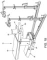
- Cushion 65 resides on base 55 of table extender 10.
- Cushion 65 preferably has a thickness (or height) which is substantially the same as the thickness (or height) of cushion 50 of surgical table 15.
- Cushion 65 is also formed out of a radiolucent material such that X-ray and/or CT imaging may be performed on the anatomy residing on table extender 10.
- a recess 107 may be provided in the distal portion of cushion 65 so as to expose distal openings 80 in base 55.
- table extender 10 is nearly completely radiolucent, i.e., the only portions of table extender 10 which are not radiolucent are mounts 60 (which are preferably formed out of a radiopaque metal, e.g., stainless steel).
- mounts 60 which are preferably formed out of a radiopaque metal, e.g., stainless steel.
- the only portion of table extender 10 which is not radiolucent in the region extending away from surgical table 15 is the distal portions of mounts 60 (i.e., the portions of bodies 85 of mounts 60 which extend alongside or beneath base 55 of table extender 10).
- greater than approximately 90% of the surface area of table extender 10 is radiolucent (as viewed from a vertical or anterior/posterior perspective).
- table extender 10 In another preferred form of the invention, greater than approximately 80% of the surface area of table extender 10 is radiolucent. Of particular note, the middle and distal portions of table extender 10 are completely radiolucent. The distal sections of mounts 60 do not extend to the middle and distal portions of table extender 10, and there is no metal reinforcement across the width of table extender 10 to support the patient's weight as with existing table extenders. The carbon fiber construction of base 55 of table extender 10 is able to support the weight of the anatomy carried by base 55 without requiring additional structural reinforcements. This is a significant improvement over the prior art as it allows for better imaging and maneuverability of the X-ray equipment; one example of the prior art is U.S. Patent No. 8,944,065 .
- table extender 10 is grasped via side openings 75, and then table extender 10 is moved towards surgical table 15 so that slots 90 of mounts 60 are aligned with side rails 40 of surgical table 15.
- clamps 95 of mounts 60 are pivoted upward relative to bodies 85 of mounts 60 as mounts 60 of table extender 10 are slid over side rails 40 of surgical table 15, with side rails 40 being received in slots 90 of mounts 60.
- table extender 10 has been properly positioned relative to surgical table 15, clamps 95 are pivoted downwardly so that recesses 100 of clamps 95 seat over mounts 45 of side rails 40.
- locking screws 105 are used to further secure mounts 60 to side rails 40 (and hence to further secure table extender 10 to surgical table 15).
- table extender 10 is preferably sized so as to support the patient from a point proximal to the hips to a point proximal to the knees (see Fig. 1 ), whereby to provide optimal support for hip distraction, particularly when the patient is positioned in the so-called "Trendelenburg position" during hip surgery.
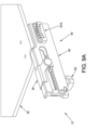
- table extender 10 comprises an inclinometer 107A to show its angle of incline (and hence to show the angle of incline of surgical table 15).
- Mounts 60 extend approximately 7 inches along the length of base 55 of table extender 10 (i.e., mounts 60 extend approximately 7 inches distal from the proximal edge of base 55 of table extender 10).
- the patient is positioned such that their hip joint is approximately 7-15 inches distal to the proximal edge of base 55 of table extender 10.
- the patient's hip can be X-ray'd without interference from mounts 60, which is important inasmuch as mounts 60 are typically made of a radiopaque material such as stainless steel.
- the hip joint is preferably positioned proximal to the distal edge of base 55 of table extender 10; this provides some margin of safety from the possibility of the patient falling off the distal end of table extender 10 in the event the patient's hip moves distally on table extender 10.
- the hip joint may shift slightly in the direction of the force (i.e., the hip joint may move slightly in the distal direction). Having a portion of table extender 10 distal to the hip joint provides a safety margin from the possibility of the hip joint sliding off the distal end of the table extender, resulting in the patient falling to the floor.
- the patient's hip is positioned approximately one-third to approximately two-thirds of the distance distal to the proximal edge of base 55 of table extender 10.
- table extender 10 there is a practical limit to the maximum length of table extender 10. If the table extender is too long, then more of the patient's body may be placed on the table extender, requiring the table extender to bear additional weight of the patient. This may require larger mounts 60 and/or increased thickness of base 55 of table extender 10, neither of which is desirable as they may decrease the radiolucency of the system. Also, an increased length to table extender 10 may require a distraction system which extends further away from surgical table 15. This is not preferred inasmuch as it generally increases the size and weight of the distraction system, making it more difficult to physically manipulate and manage by the hospital staff; and this is also not preferred inasmuch as the larger distraction system may not fit into some operating rooms (some older facilities have smaller operating rooms). In one form of the invention, base 55 of table extender 10 is approximately as long as the average length of a human femur bone (which is approximately 19 inches long).
- stabilizing pad 20 is provided to cover the top surface of surgical table 15, and the top surface of table extender 10, so as to increase the friction between the patient and surgical table 15/table extender 10, whereby to reduce the possibility of the patient inadvertently sliding on surgical table 15 and table extender 10, particularly during hip distraction and/or leg manipulation and/or during "Trandelenburg positioning".
- stabilizing pad 20 is placed on top of cushion 50 of surgical table 15 and cushion 65 of table extender 10.
- stabilizing pad 20 can terminate at another location, e.g., in the mid-back region of the patient.
- stabilizing pad 20 comprises a bottom surface 108 for contacting surgical table 15 (i.e., cushion 50 of surgical table 15) and table extender 10 (i.e., cushion 65 of table extender 10), and a top surface 109 for receiving the patient.
- Bottom surface 108 preferably comprises a high friction material for preventing stabilizing pad 20 from sliding relative to surgical table 15 (i.e., relative to cushion 50 of surgical table 15) and table extender 10 (i.e., relative to cushion 65 of table extender 10).
- Top surface 109 preferably comprises a high friction material for preventing a patient from sliding relative to stabilizing pad 20.
- top surface 109 of stabilizing pad 20 is made of a material which is suitable for contacting the skin of a patient, with respect to both patient compatibility and comfort, while also increasing friction with the patient.
- top surface 109 of stabilizing pad 20 is made of an open cell polyurethane foam.
- stabilizing pad 20 comprises a foam base 110 (which includes the aforementioned bottom surface 108) and a foam upper 115 (which includes the aforementioned top surface 109).
- foam base 110 is sufficiently dense to provide a stable contact with cushion 50 of surgical table 15 and with cushion 65 of table extender 10
- foam upper 115 is flexible enough to allow the patient to sink into the stabilizing pad, increasing the overall contact and effective frictional resistance to sliding in a relatively stable support structure. It should be noted that some foam materials and shapes may be superior for creating sliding friction against human skin, while other materials and shapes may be superior for creating sliding friction against the top surfaces of surgical table 15 and table extender 10.
- foam upper 115 is an open cell polyurethane foam comprising an "egg crate" top surface 109 so as to further enhance friction between the patient and stabilizing pad 20 while still being comfortable for contacting the skin of the patient.
- foam base 110 is preferably a closed cell foam (e.g., ethylene-vinyl acetate (EVA)) comprising a flat bottom surface 108.
- EVA ethylene-vinyl acetate
- foam base 110 has a higher density than foam upper 115.
- foam base 110 out of a higher density closed cell foam (e.g., ethylene-vinyl acetate (EVA)) and by forming foam upper 115 out of a lower density open cell foam (e.g., polyurethane foam) allows the foam base to provide a stable, high friction foundation on surgical table 15 and allows foam upper 115 to provide a contouring, high friction support beneath and around the patient.
- a higher density closed cell foam e.g., ethylene-vinyl acetate (EVA)
- foam upper 115 e.g., polyurethane foam
- one or more patient straps 22 are also provided to secure the patient to surgical table 15. More particularly, one or more patient straps 22 may be passed over the torso of the patient, under the arms of the patient and attached to surgical table 15. Patient straps 22 prevent the patient from rolling on surgical table 15. Patient straps 22 may also be made so as to prevent the patient from sliding longitudinally on the surgical table. Thus, patient straps 22 provide a counterforce to the anatomy during post-less hip distraction.
- patient straps 22 provide an added margin of safety for the patient during a Trendelenburg procedure when surgical table 15 is tilted so that the patient's head is angled towards the floor and the patient's feet are angled towards the ceiling, i.e., to prevent the patient from sliding or rolling on surgical table 15.
- patient straps 22 may extend completely around platform 35 of surgical table 15. Additionally and/or alternatively, patient straps 22 may be configured for attachment to side rails 40 of surgical table 15, e.g., the ends of patient straps 22 may be provided with hook-and-loop fasteners for securing patient straps 22 to side rails 40 of surgical table 15.
- stabilizing pad 20 further comprises handles (or grips) 126.
- handles or grips
- a patient onto, and off of, surgical table 15 e.g., from a gurney
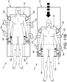
- the surgical staff slides the patient distally on surgical table 15 until the patient's hips are properly positioned on table extender 10 (e.g., in the manner described above).
- the patient's knees will be just off table extender 10 (e.g., in the manner also described above).
- this transfer of the patient from a more cephalad position on the surgical table during preparation to a more distal (caudal) position on the surgical table for distraction does not present a problem: most surgical tables have a cushion (e.g., cushion 50) on top of platform 35 of the surgical table, and this cushion can typically accommodate sliding a patient on cushion 50.
- stabilizing pad 20 has a higher degree of friction than a standard cushion; therefore, it may be too difficult to slide the patient on stabilizing pad 20 and the surgical staff must resort to lifting the patient in order to move the patient relative to surgical table 15 and table extender 10. This is not desirable as it can lead to back injuries for the surgical staff.
- stabilizing pad 20 comprises handles 126 which can be utilized to slide the stabilizing pad (and hence the patient) along cushion 50. See Fig. 11B .
- Stabilizing pad 20 may comprise reinforcement structures 127 between opposing handles 126 so that stabilizing pad 20 can support the patient's weight (e.g., a strap 127 extending across the width of the pad from one handle 126 to another handle 126 located on the opposite side of stabilizing pad 20).
- stabilizing pad 20 may comprise a sheet of strong material (not shown) interposed between foam base 110 and foam upper 115, e.g., a strong sheet of material interposed between a foam base 110 and a foam upper 115.
- stabilizing pad 20 may comprise one or more markings 128 for indicating the preferred location of the patient's hip joints on stabilizing pad 20 in the caudal/cephalad direction. These markings 128 help ensure that, once stabilizing pad 20 (with the patient thereon) is moved to the surgical position, the patient's hip joints will be located on table extender 10 in the preferred position (i.e., proximal to mounts 60 yet spaced from the distal edge of base 55 of table extender 10).
- a low-friction (e.g., lubricious) transfer sheet 129 ( Figs. 11C and 11D ) is disposed between the patient and stabilizing pad 20 before and during patient transfer, and then the low-friction (e.g., lubricious) transfer sheet is removed prior to the start of the surgery (including distraction of the hip).
- the low-friction (e.g., lubricious) transfer sheet is removed prior to the start of the surgery (including distraction of the hip).
- stabilizing pad 20 is placed on, and secured to, surgical table 15 in the surgical position.
- a low-friction (e.g., lubricious) transfer sheet 129 Figs. 11C and 11D ) can be used.
- raised lateral sections 135 may limit access to surgical portals and/or restrict hand movements by the surgical team, raised lateral sections 135 may extend along only portions of the patient's sides, e.g., in the case of hip surgery, raised lateral section 135 may extend along the torso of the patient but terminate at, or proximal to, the hip region of the patient.
- leg support 140 can be provided to support the patient's legs until such time as the patient's legs are secured in the distraction apparatus.
- leg support 140 is a tray which mounts to distal end 53 of table extender 10 and extends distally of table extender 10.
- leg support 140 may mount to surgical table 15 and extend distally of table extender 10.
- Leg support 140 may also have a support (not shown) which extends to the floor for additional support.
Landscapes
- Health & Medical Sciences (AREA)
- Life Sciences & Earth Sciences (AREA)
- General Health & Medical Sciences (AREA)
- Biomedical Technology (AREA)
- Engineering & Computer Science (AREA)
- Animal Behavior & Ethology (AREA)
- Public Health (AREA)
- Veterinary Medicine (AREA)
- Surgery (AREA)
- Orthopedic Medicine & Surgery (AREA)
- Nuclear Medicine, Radiotherapy & Molecular Imaging (AREA)
- Heart & Thoracic Surgery (AREA)
- Medical Informatics (AREA)
- Molecular Biology (AREA)
- Accommodation For Nursing Or Treatment Tables (AREA)
Claims (12)
- Tischverlängerung (10), dazu konfiguriert, mit einem Operationstisch (15), der Seitenschienen (40), die sich entlang der Seiten einer Plattform (35) des Operationstisches erstrecken und von der Plattform auf Schienenhalterungen (45) beabstandet sind, aufweist, verbunden zu werden, die Tischverlängerung umfassend:eine Basis (55), mit einem Proximalabschnitt (57), einem Distalabschnitt (56) und einem zwischen dem Proximalabschnitt und dem Distalabschnitt angeordneten Zwischenabschnitt; undein Halterungenpaar (60) zum Montieren der Basis (55) der Tischverlängerung an den Seitenschienen (40) des Operationstisches; undeinen Neigungsmesser (107A) zum Anzeigen der Winkelanordnung der Tischverlängerung relativ zur Horizontalen, wobei der Neigungsmesser an einer Aufnahme des Halterungenpaares (60) befestigt ist;wobei der distale Abschnitt der Tischverlängerung und der Zwischenabschnitt der Tischverlängerung im Wesentlichen vollständig röntgenstrahlendurchlässig sind,wobei sich distale Sektionen der Halterungen (60) nicht bis zu den Zwischen- und Distalabschnitten der Tischverlängerung (10) erstrecken und es keine Metallverstärkung über die Breite der Tischverlängerung (10) gibt, sodass die einzigen nicht röntgenstrahlendurchlässigen Abschnitte der Tischverlängerung (10) die Halterungen (60) sind,wobei die Tischverlängerung so dimensioniert ist, dass sie einen Patienten von einem Punkt proximal zu den Hüften des Patienten bis zu einem Punkt proximal zum Knie des Patienten stützt.
- Tischverlängerung nach Anspruch 1, wobei die Tischverlängerung wenigstens eine Markierung zum Angeben der gewünschten Position des Hüftgelenks eines Patienten auf der Tischverlängerung aufweist.
- Tischverlängerung nach Anspruch 1, wobei die Tischverlängerung ungefähr die Länge eines menschlichen Femurs aufweist.
- Tischverlängerung nach einem der vorhergehenden Ansprüche, wobei die Tischverlängerung so dimensioniert ist, dass das Hüftgelenk des Patienten proximal zum distalen Abschnitt der Tischverlängerung positioniert ist, wenn ein Patient auf der Tischverlängerung angeordnet ist.
- Tischverlängerung nach einem der Ansprüche 1 bis 4, wobei mehr als etwa 80 %, z. B. mehr als etwa 90 %, der Oberfläche der Tischverlängerung röntgenstrahlendurchlässig ist.
- Tischverlängerung nach Anspruch 1, wobei die Tischverlängerung dazu konfiguriert ist, eine laterale Röntgenaufnahme der Hüfte eines Patienten ohne Bildbehinderung zu ermöglichen.
- Tischverlängerung nach Anspruch 1, ferner umfassend eine am distalen Abschnitt der Tischverlängerung montierte Beinstütze (140), wobei die Beinstütze optional von der Tischverlängerung abnehmbar ist.
- Tischverlängerung nach einem der Ansprüche 1-7, wobei die Tischverlängerung
wenigstens eine oder mehrere Öffnungen aufweist, wie- seitliche Öffnungen (75), um einfaches Greifen der Tischverlängerung zu ermöglichen und/oder Gurte einer Stabilisierungsauflage aufzunehmen, oder- eine distale Öffnung (80), um die Montage anderer Ausrüstung, wie z. B. eines Ständers, an der Tischverlängerung zu ermöglichen. - Kombination aus einer Tischverlängerung nach einem der Ansprüche 1 bis 8 und einer Stabilisierungsauflage (20), dazu konfiguriert
auf mindestens einem Teil des Operationstisches und der Tischverlängerung angeordnet zu sein, wobei die Stabilisierungsauflage umfasst:eine Oberseite (109) mit hoher Reibung; undeine Unterseite (108) mit hoher Reibung;wobei die Stabilisierungsauflage Schaumstoff aufweist. - Kombination nach Anspruch 9, wobei der Schaum der unteren Unterseite (108) eine höhere Dichte aufweist als der Schaum der Oberseite (109).
- Kombination nach Anspruch 9, wobei die Stabilisierungsauflage zur Befestigung an Seitenschienen (40) eines Operationstisches konfiguriert ist, wobei die Stabilisierungsauflage optional Gurte (125) zur Befestigung an den Seitenschienen eines Operationstisches aufweist.
- Kombination nach Anspruch 9, wobei die Stabilisierungsauflage mindestens eine Markierung (128) zur Angabe der gewünschten Position der Hüftgelenke eines Patienten auf der Stabilisierungsauflage aufweist.
Applications Claiming Priority (3)
| Application Number | Priority Date | Filing Date | Title |
|---|---|---|---|
| US201762455143P | 2017-02-06 | 2017-02-06 | |
| US201762546600P | 2017-08-17 | 2017-08-17 | |
| PCT/US2018/017088 WO2018145102A1 (en) | 2017-02-06 | 2018-02-06 | Method and apparatus for supporting and stabilizing a patient during hip distraction |
Publications (3)
| Publication Number | Publication Date |
|---|---|
| EP3576687A1 EP3576687A1 (de) | 2019-12-11 |
| EP3576687A4 EP3576687A4 (de) | 2021-03-10 |
| EP3576687B1 true EP3576687B1 (de) | 2025-07-02 |
Family
ID=63038458
Family Applications (1)
| Application Number | Title | Priority Date | Filing Date |
|---|---|---|---|
| EP18747256.8A Active EP3576687B1 (de) | 2017-02-06 | 2018-02-06 | Verfahren und vorrichtung zur unterstützung und stabilisierung eines patienten bei der hüftdistraktion |
Country Status (5)
| Country | Link |
|---|---|
| US (2) | US11684532B2 (de) |
| EP (1) | EP3576687B1 (de) |
| AU (1) | AU2018214679A1 (de) |
| CA (1) | CA3052654A1 (de) |
| WO (1) | WO2018145102A1 (de) |
Families Citing this family (13)
| Publication number | Priority date | Publication date | Assignee | Title |
|---|---|---|---|---|
| CA2872583C (en) | 2013-11-27 | 2022-06-07 | Sage Products, Llc | Apparatus and system for turning and positioning a patient |
| WO2016197142A1 (en) | 2015-06-05 | 2016-12-08 | The Regents Of The University Of Colorado, A Body Corporate | Surgical table and accessories to facilitate hip arthroscopy |
| US10765576B2 (en) | 2015-08-18 | 2020-09-08 | Sage Products, Llc | Apparatus and system for boosting, transferring, turning and positioning a patient |
| US9849053B2 (en) | 2015-08-18 | 2017-12-26 | Sage Products, Llc | Apparatus and system for boosting, transferring, turning and positioning a patient |
| EP3576684B1 (de) | 2017-02-06 | 2025-08-20 | Stryker Corporation | Distraktionsrahmen für hüftdistraktion |
| WO2018232012A1 (en) | 2017-06-13 | 2018-12-20 | Sage Products, Llc | Patient positioning and support system |
| US11090214B2 (en) * | 2018-08-06 | 2021-08-17 | United Metal Fabricators, Inc. | Leg support assembly for medical examination device |
| US11324652B2 (en) | 2018-08-21 | 2022-05-10 | Sage Products, Llc | Systems and methods for lifting and positioning a patient |
| JP7530887B2 (ja) | 2018-09-20 | 2024-08-08 | エッグ メディカル,インコーポレイテッド | 放射線画像診断及び医療装置一体化のためのスレッドテーブル |
| WO2021158488A1 (en) | 2020-02-03 | 2021-08-12 | Alphatec Spine, Inc | Patient positioning system |
| US11564855B2 (en) * | 2020-09-28 | 2023-01-31 | Stryker Corporation | Systems and methods for supporting and stabilizing a patient during hip distraction |
| US11890240B2 (en) | 2021-04-30 | 2024-02-06 | Sage Products, Llc | Method and device for turning and positioning a patient using fillable chambers |
| US12508182B2 (en) | 2023-04-26 | 2025-12-30 | Sage Products, Llc | Sheet assembly for positioning a patient |
Citations (1)
| Publication number | Priority date | Publication date | Assignee | Title |
|---|---|---|---|---|
| US20160287461A1 (en) * | 2015-04-01 | 2016-10-06 | Michael L. Naughton | Surgical table with combination footboard and patient transfer board |
Family Cites Families (189)
| Publication number | Priority date | Publication date | Assignee | Title |
|---|---|---|---|---|
| US2732269A (en) | 1956-01-24 | Arm and leg support | ||
| US2150314A (en) | 1935-10-28 | 1939-03-14 | Gilbert Hyde Chick | Orthopedic apparatus |
| US3220022A (en) | 1963-12-23 | 1965-11-30 | Nelson Ted | Hospital bed sliding foot section |
| US3745996A (en) | 1971-02-19 | 1973-07-17 | Berivon Co | Apparatus for the reduction of bone fractures |
| CH562015A5 (de) | 1972-03-21 | 1975-05-30 | Weinmann Ag | |
| USD264531S (en) | 1980-02-12 | 1982-05-25 | Trode Varley P | Portable fish filleting table |
| US4573482A (en) | 1982-07-02 | 1986-03-04 | Arthro-Medic, Inc. | Arthroscopic surgery method |
| CH650387A5 (de) | 1982-12-27 | 1985-07-31 | Raichle Sportschuh Ag | Sportschuh, insbesondere skischuh. |
| DE3317771A1 (de) | 1983-04-26 | 1984-10-31 | Weinmann Gmbh & Co Kg Fahrrad- Und Motorrad-Teilefabrik, 7700 Singen | Skischuh mit zentralverschluss |
| US4708510A (en) | 1986-04-17 | 1987-11-24 | Mcconnell Bernard E | Ball joint coupling |
| FR2608384B1 (fr) | 1986-12-17 | 1989-05-05 | Salomon Sa | Dispositif pour caler le talon du pied du porteur dans une chaussure de ski |
| CH672232A5 (de) | 1987-02-04 | 1989-11-15 | Lange Int Sa | |
| US4865303A (en) * | 1987-11-23 | 1989-09-12 | American Sterilizer Company | Operating table |
| US5177882A (en) | 1989-06-03 | 1993-01-12 | Puma Ag Rudolf Dassler Sport | Shoe with a central fastener |
| US5052128A (en) | 1989-07-24 | 1991-10-01 | Robert Lonardo | Padded boot means for invalid patients |
| US5249377A (en) | 1990-01-30 | 1993-10-05 | Raichle Sportschuh Ag | Ski boot having tensioning means in the forefoot region |
| US5162039A (en) | 1992-01-21 | 1992-11-10 | Dahners Laurence E | Distraction and reduction device |
| US5306231A (en) | 1992-10-26 | 1994-04-26 | Harry Cullum | Traction system for a patient in a bed |
| US5287575A (en) | 1992-11-09 | 1994-02-22 | Allen Medical Systems | Hand table |
| US5582379A (en) | 1994-06-24 | 1996-12-10 | Allen Medical Systems | Adjustable limb support system |
| US5560577A (en) | 1994-06-24 | 1996-10-01 | Allen Medical Systems | Adjustable limb support system |
| US5608934A (en) | 1994-10-06 | 1997-03-11 | Smith & Nephew Dyonics, Inc. | Hip distractor |
| CN1145459C (zh) | 1995-03-01 | 2004-04-14 | 史密夫和内修有限公司 | 立体固定架 |
| US5728095A (en) | 1995-03-01 | 1998-03-17 | Smith & Nephew, Inc. | Method of using an orthopaedic fixation device |
| US5971984A (en) | 1995-03-01 | 1999-10-26 | Smith & Nephew, Inc. | Method of using an orthopaedic fixation device |
| JP2764805B2 (ja) | 1996-01-26 | 1998-06-11 | 株式会社シマノ | スノーボードブーツのバックサポート |
| US5918330A (en) | 1996-08-14 | 1999-07-06 | Allen Medical Systems, Inc. | Ratchet mechanism for booted surgical stirrup |
| USD385040S (en) | 1996-09-03 | 1997-10-14 | Allen Medical Systems | Boot for surgical stirrup |
| USD389580S (en) | 1996-10-28 | 1998-01-20 | Allen Medical Systems | Surgical armboard |
| USD387581S (en) | 1996-11-04 | 1997-12-16 | Just Wheels & Tire Co. | Wheel display stand |
| US5802641A (en) | 1997-03-07 | 1998-09-08 | Amatech Corporation | Leg holder system for simultaneous positioning in the abduction and lithotomy dimensions |
| US7591050B2 (en) | 1997-08-22 | 2009-09-22 | Boa Technology, Inc. | Footwear lacing system |
| US6754923B2 (en) * | 1997-11-07 | 2004-06-29 | Hill-Rom Services, Inc. | Leg section support for a surgical table |
| US6109625A (en) | 1998-03-13 | 2000-08-29 | Htc Products, Inc. | Mobile base |
| US6286164B1 (en) | 1998-03-19 | 2001-09-11 | Orthopedic Systems, Inc. | Medical table having controlled movement and method of use |
| US6162223A (en) | 1999-04-09 | 2000-12-19 | Smith & Nephew, Inc. | Dynamic wrist fixation apparatus for early joint motion in distal radius fractures |
| AU2001234878A1 (en) | 2000-02-07 | 2001-08-14 | Hill-Rom Services, Inc. | Bariatric surface for an operating room table |
| JP2005514157A (ja) | 2001-12-21 | 2005-05-19 | スミス アンド ネフュー インコーポレーテッド | ヒンジ式関節システム |
| SE524031C2 (sv) | 2002-01-18 | 2004-06-15 | Bo Tillander | Anordning för fixering av en patient, särskilt vid höftledskirurgi |
| US7189214B1 (en) | 2002-01-22 | 2007-03-13 | The Saunders Group, Inc. | Multi-axis cervical and lumbar traction table |
| AU2003217389B2 (en) | 2002-02-11 | 2008-10-30 | Smith & Nephew, Inc. | Image-guided fracture reduction |
| JP4527929B2 (ja) | 2002-05-08 | 2010-08-18 | 衛 光石 | 整復装置 |
| CA2440681A1 (en) | 2002-09-10 | 2004-03-10 | Anthony T. D'amico | Traction device for physical therapy |
| US20040133983A1 (en) | 2003-01-13 | 2004-07-15 | Newkirk David C. | Surgical table |
| US20040133979A1 (en) | 2003-01-13 | 2004-07-15 | Newkirk David C. | Orthopedic table apparatus |
| US7677249B2 (en) | 2003-04-16 | 2010-03-16 | The University Of Hong Kong | Device and method for providing a lateralization effect |
| JP4520710B2 (ja) | 2003-05-22 | 2010-08-11 | 衛 光石 | パワーアシスト制御装置およびパワーアシスト制御方法、ならびに整復装置 |
| US7862570B2 (en) | 2003-10-03 | 2011-01-04 | Smith & Nephew, Inc. | Surgical positioners |
| US7337483B2 (en) | 2004-01-23 | 2008-03-04 | Allen Medical Systems, Inc. | Surgical positioning apparatus |
| JP2007531596A (ja) | 2004-03-31 | 2007-11-08 | スミス アンド ネフュー インコーポレーテッド | 基準アレイ入力装置を提供する方法及び装置 |
| AU2005237479B8 (en) | 2004-04-21 | 2011-09-29 | Smith & Nephew, Inc. | Computer-aided methods for shoulder arthroplasty |
| DE102004025612A1 (de) | 2004-04-22 | 2005-11-10 | Plus Endoprothetik Ag | Einrichtung zum Erfassen einer Kraft-Weg-Kennlinie eines oder mehrerer Bänder, sowie Verfahren zur Erfassung der Kennlinie |
| US7211056B2 (en) | 2004-08-28 | 2007-05-01 | Danuta Grazyna Petelenz | Device for chest and abdominal compression CPR |
| WO2006052765A2 (en) | 2004-11-04 | 2006-05-18 | Smith & Nephew, Inc. | Cycle and load measurement device |
| US20060100562A1 (en) | 2004-11-09 | 2006-05-11 | Pamplin James C | Hip distraction system |
| US7600281B2 (en) | 2004-11-10 | 2009-10-13 | Allen Medical Systems, Inc. | Body support apparatus for spinal surgery |
| US7520007B2 (en) | 2004-11-10 | 2009-04-21 | Allen Medical Systems, Inc. | Accessory rail clamp with latch and lock mechanisms |
| US7520008B2 (en) | 2004-11-10 | 2009-04-21 | Allen Medical Systems | Surgical table extension |
| US7882583B2 (en) | 2004-11-10 | 2011-02-08 | Allen Medical Systems, Inc. | Head support apparatus for spinal surgery |
| US7669262B2 (en) | 2004-11-10 | 2010-03-02 | Allen Medical Systems, Inc. | Accessory frame for spinal surgery |
| DE102004054332A1 (de) | 2004-11-10 | 2006-05-11 | Memminger, Michael, Dr. | Beinführung, insbesondere für die Verwendung bei einer Hüftoperation |
| WO2006066116A2 (en) | 2004-12-17 | 2006-06-22 | Steelcase Development Corporation | Height adjustable table |
| US7152261B2 (en) | 2005-02-22 | 2006-12-26 | Jackson Roger P | Modular multi-articulated patient support system |
| US20140033434A1 (en) | 2005-02-22 | 2014-02-06 | Roger P. Jackson | Cantilevered patient positioning support structure |
| US9468576B2 (en) | 2005-02-22 | 2016-10-18 | Roger P. Jackson | Patient support apparatus with body slide position digitally coordinated with hinge angle |
| US9295433B2 (en) | 2005-02-22 | 2016-03-29 | Roger P. Jackson | Synchronized patient elevation and positioning apparatus for use with patient positioning support systems |
| US8055487B2 (en) | 2005-02-22 | 2011-11-08 | Smith & Nephew, Inc. | Interactive orthopaedic biomechanics system |
| US9265679B2 (en) | 2005-02-22 | 2016-02-23 | Roger P Jackson | Cantilevered patient positioning support structure |
| US20150059094A1 (en) | 2005-02-22 | 2015-03-05 | Roger P. Jackson | Patient positioning support structure |
| US9301897B2 (en) | 2005-02-22 | 2016-04-05 | Roger P. Jackson | Patient positioning support structure |
| US7565708B2 (en) | 2005-02-22 | 2009-07-28 | Jackson Roger P | Patient positioning support structure |
| US8707484B2 (en) | 2005-02-22 | 2014-04-29 | Roger P. Jackson | Patient positioning support structure |
| US7739762B2 (en) | 2007-10-22 | 2010-06-22 | Mizuho Orthopedic Systems, Inc. | Surgery table apparatus |
| US9308145B2 (en) | 2005-02-22 | 2016-04-12 | Roger P. Jackson | Patient positioning support structure |
| US8844077B2 (en) | 2005-02-22 | 2014-09-30 | Roger P. Jackson | Syncronized patient elevation and positioning apparatus positioning support systems |
| US9186291B2 (en) | 2005-02-22 | 2015-11-17 | Roger P. Jackson | Patient positioning support structure with trunk translator |
| US9744087B2 (en) | 2005-02-22 | 2017-08-29 | Roger P. Jackson | Patient support apparatus with body slide position digitally coordinated with hinge angle |
| US9849054B2 (en) | 2005-02-22 | 2017-12-26 | Roger P. Jackson | Patient positioning support structure |
| US20130133137A1 (en) | 2011-11-28 | 2013-05-30 | Roger P. Jackson | Patient positioning support structure with coordinated continuous nonsegmented articulation, rotation and lift, and locking fail-safe device |
| DE102005023477A1 (de) | 2005-04-28 | 2006-11-09 | Plus Orthopedics Ag | Vorrichtung zur Lagerung eines Patienten für eine minimalinvasive Implantation eines künstlichen Hüftgelenks |
| US20060271056A1 (en) | 2005-05-10 | 2006-11-30 | Smith & Nephew, Inc. | System and method for modular navigated osteotome |
| AU2006280003B2 (en) | 2005-08-10 | 2012-06-07 | Orthopedic Systems, Inc. | Medical table having controlled movement and method of use |
| CN103637840A (zh) | 2005-08-23 | 2014-03-19 | 史密夫和内修有限公司 | 遥测矫形植入物 |
| US7947006B2 (en) | 2005-11-30 | 2011-05-24 | Smith & Nephew, Inc. | Hip distraction |
| US7832401B2 (en) | 2005-11-30 | 2010-11-16 | Smith & Nephew, Inc. | Hip distraction |
| EP2007318B8 (de) | 2006-03-20 | 2014-03-12 | Smith & Nephew, Inc. | Hüftpfannen-anordnung für multiple lagermaterialien |
| US7949386B2 (en) | 2006-03-21 | 2011-05-24 | A2 Surgical | Computer-aided osteoplasty surgery system |
| USD546599S1 (en) | 2006-04-10 | 2007-07-17 | Global Equipment Company, Inc. | Portions of a right side shelf and cabinet drawer |
| USD665912S1 (en) | 2006-04-11 | 2012-08-21 | Allen Medical Systems, Inc. | Head support pad for surgery |
| US20070277350A1 (en) | 2006-06-05 | 2007-12-06 | Stephen Hines | Leveling caster system and method of using same |
| US8011045B2 (en) | 2006-06-12 | 2011-09-06 | Allen Medical Systems, Inc. | Localized patient support |
| US8037884B2 (en) | 2006-10-02 | 2011-10-18 | Allen Medical Systems, Inc. | Modular system for patient positioning during medical procedures |
| US7949006B2 (en) | 2006-11-09 | 2011-05-24 | Motorola Mobility, Inc. | System and method for media burst control of discrete content for push-to-cellular communication |
| US7650654B2 (en) * | 2007-03-05 | 2010-01-26 | Stryker Corporation | Transfer device |
| EP2002870B1 (de) | 2007-06-14 | 2011-08-17 | Goodwell International Limited | Werkzeugfrei einstellbare Bindung für Snowboards |
| EP2002796B1 (de) | 2007-06-15 | 2012-08-08 | BrainLAB AG | Computergestütztes Planungsverfahren für die Korrektur von Gelenkknochen-Formveränderungen |
| IL184151A0 (en) | 2007-06-21 | 2007-10-31 | Diagnostica Imaging Software Ltd | X-ray measurement method |
| US7913336B2 (en) * | 2007-08-14 | 2011-03-29 | Stryker Corporation | Shearless pivot for bed |
| US8397323B2 (en) | 2007-08-24 | 2013-03-19 | Allen Medical Systems, Inc. | Surgical table accessory platform |
| AU2008296209B2 (en) | 2007-09-06 | 2014-05-29 | Smith & Nephew, Inc. | System and method for communicating with a telemetric implant |
| WO2009062545A1 (en) | 2007-11-13 | 2009-05-22 | Schaerer Mayfield Medical Ag | Modular device for positioning and immobilisation of a patient's body for surgical operations and corresponding operating table |
| US8702712B2 (en) | 2007-12-06 | 2014-04-22 | Smith & Nephew, Inc. | Systems and methods for determining the mechanical axis of a femur |
| EP2259751B1 (de) | 2008-02-25 | 2014-11-05 | Smith & Nephew, Inc. | System zur abbildung des femurkopfes zur ausrichtung einer gelenkpfannenprothese |
| WO2009139895A1 (en) | 2008-05-15 | 2009-11-19 | Ossur Hf | Orthopedic devices utilizing rotary tensioning |
| US8322342B2 (en) | 2008-07-25 | 2012-12-04 | Allen Medical Systems, Inc. | Operative arm support |
| EP2364115B1 (de) | 2008-10-15 | 2019-02-20 | Smith & Nephew, Inc. | Interne komposit-fixatoren |
| DE202008014021U1 (de) | 2008-10-21 | 2009-02-12 | Condor Gmbh Medicaltechnik | Zug- und Drehtisch, insbesondere für die Hüft-Endoprothetik und Unfallchirurgie |
| TW201034646A (en) * | 2009-03-17 | 2010-10-01 | Amtai Medical Equipment Co Ltd | Operating table |
| US8690806B2 (en) | 2009-09-02 | 2014-04-08 | Allen Medical Systems, Inc. | Surgical positioning system |
| US8690807B2 (en) | 2009-09-02 | 2014-04-08 | Allen Medical Systems, Inc. | Surgical positioning system |
| US8469911B2 (en) | 2009-09-02 | 2013-06-25 | Eugene Lloyd Hiebert | Surgical positioning system |
| DE102009047869B4 (de) | 2009-09-30 | 2014-06-05 | Maquet Gmbh & Co. Kg | Adapter zum Anschluss mindestens eines Zubehörgerätes an einen OP-Tisch und System, umfassend einen OP-Tisch, mindestens ein Zubehörgerät und einen Adapter |
| EP3653187B1 (de) * | 2009-12-14 | 2022-01-26 | Hill-Rom Services, Inc. | Patiententragevorrichtungen mit übungsfunktionen |
| US9526349B2 (en) | 2009-12-17 | 2016-12-27 | Stryker Corporation | Patient support cover |
| US8707486B2 (en) | 2010-02-16 | 2014-04-29 | Allen Medical Systems, Inc. | Lacing system to secure a limb in a surgical support apparatus |
| US8833707B2 (en) | 2010-07-15 | 2014-09-16 | Allen Medical Systems, Inc. | Disposable urology drainage bag |
| MX2013002227A (es) | 2010-08-26 | 2013-05-09 | Smith & Nephew Inc | Implantes, metodos quirurgicos e instrumental para uso en cirugias de choque femoroacetabular. |
| US10130542B1 (en) * | 2010-09-17 | 2018-11-20 | Glenn Gerald Strawder | Device for positioning the neck of a person in the flexion and extension positions |
| US20120073476A1 (en) | 2010-09-28 | 2012-03-29 | Hsiu-Chen Lai | Drop leaf table angular adjustment mechanism |
| CN103442650A (zh) | 2010-11-12 | 2013-12-11 | 史密夫和内修有限公司 | 用于提升身体内的组织的可膨胀的可转向的气囊 |
| US8555439B2 (en) | 2010-11-18 | 2013-10-15 | Allen Medical Systems, Inc. | Padded head support |
| US8893333B2 (en) | 2010-11-18 | 2014-11-25 | Allen Medical Systems, Inc. | Surgical head support apparatus |
| US8806679B2 (en) | 2010-11-18 | 2014-08-19 | Allen Medical Systems, Inc. | Operating room table adapter |
| US9072646B2 (en) | 2010-12-14 | 2015-07-07 | Allen Medical Systems, Inc. | Lateral surgical platform with rotation |
| WO2012103169A2 (en) | 2011-01-25 | 2012-08-02 | Smith & Nephew, Inc. | Targeting operation sites |
| EP2484315B1 (de) | 2011-02-07 | 2014-06-11 | Arthrex, Inc. | Prothese für minimal-invasiven Hüftgelenkstotalersatz |
| DE202011000308U1 (de) | 2011-02-10 | 2011-04-21 | Maquet Gmbh & Co. Kg | Extensionsvorrichtung |
| AU2012229158B2 (en) | 2011-03-11 | 2016-01-14 | Innovative Orthopedic Technologies, Llc | Devices and methods for supporting a patient's legs |
| US20120240938A1 (en) | 2011-03-21 | 2012-09-27 | Christo Pamichev | Methods and systems for performing hip joint distraction |
| US8584281B2 (en) | 2011-04-07 | 2013-11-19 | Mizuho Orthopedic Systems, Inc | Surgery table having coordinated motion |
| DE102011016456B4 (de) | 2011-04-08 | 2016-02-25 | Condor Gmbh Medicaltechnik | Positioniervorrichtung |
| US9173649B2 (en) | 2011-04-08 | 2015-11-03 | Allen Medical Systems, Inc. | Low profile distractor apparatuses |
| US8845568B2 (en) | 2011-04-08 | 2014-09-30 | Allen Medical Systems, Inc. | Distractor straps for use with distractor apparatuses |
| US9655764B2 (en) | 2011-06-02 | 2017-05-23 | Allen Medical Systems, Inc. | Surgical foot support with handles |
| GB201115391D0 (en) * | 2011-09-06 | 2011-10-19 | Wootton Malcolm | Operating tables and accessories |
| WO2013037924A1 (fr) | 2011-09-15 | 2013-03-21 | Nicolas Frey | Chaussure de sport |
| US8986228B2 (en) | 2011-09-19 | 2015-03-24 | Trimanus Medical, Inc. | Method and apparatus for monitoring surgical traction |
| US8997749B2 (en) | 2011-09-30 | 2015-04-07 | Allen Medical Systems, Inc. | Surgical assembly |
| US8464720B1 (en) | 2012-01-10 | 2013-06-18 | Alessio Pigazzi | Method of securing a patient onto an operating table when the patient is in the trendelenburg position and apparatus therefor including a kit |
| US8511314B2 (en) | 2012-01-10 | 2013-08-20 | Khs Gmbh | Method of securing a patient onto an operating table when the patient is in the Trendelenburg position and apparatus therefor including a kit |
| JP2015506747A (ja) | 2012-01-10 | 2015-03-05 | ピガッツィ, アレッショPIGAZZI, Alessio | 患者がトレンデレンブルグ体位にある場合に患者を手術台に固定する方法及びそのためのキットを含む装置 |
| NL2008437C2 (en) | 2012-01-19 | 2013-07-22 | Clinical Graphics B V | Process to generate a computer-accessible medium comprising information on the functioning of a joint. |
| US10206842B2 (en) | 2012-01-26 | 2019-02-19 | American Sterilizer Company | Medical table with leg support |
| US9468577B2 (en) | 2012-02-06 | 2016-10-18 | Arthrex, Inc. | Perineal post pad for patient lower extremity positioning systems |
| AU2013217089B2 (en) | 2012-02-06 | 2017-02-16 | Innovative Orthopedic Technologies, Llc | Surgical table with moveable perineal post |
| US9936941B2 (en) | 2012-02-07 | 2018-04-10 | Arthrocare Corporation | Surgical instrument for manipulating and passing suture |
| US9265680B2 (en) * | 2012-03-06 | 2016-02-23 | Operating Room Safety Enterprises, LLC | Surgical table |
| US8997281B2 (en) * | 2012-03-23 | 2015-04-07 | Trumpf Medizin Systeme Gmbh + Co. Kg | Operating table top assemblies and related devices |
| DE202012101347U1 (de) | 2012-04-13 | 2012-06-27 | Condor Gmbh Medicaltechnik | Positioniervorrichtung |
| US9498397B2 (en) | 2012-04-16 | 2016-11-22 | Allen Medical Systems, Inc. | Dual column surgical support system |
| US20140173827A1 (en) | 2012-04-23 | 2014-06-26 | HUG-A-VAC Surgical Positioning Systems, Inc. | Patient positioning system |
| HRP20170469T1 (hr) | 2012-06-01 | 2017-06-02 | Joseph Gauta | Prenosiva udlaga za nogu s držačem noge |
| US20130338792A1 (en) | 2012-06-15 | 2013-12-19 | Arthrex, Inc. | Implantation of micronized allograft tissue over a microfractured defect |
| DE102012105264B4 (de) | 2012-06-18 | 2016-06-09 | MAQUET GmbH | Einrichtung zum Fixieren eines Femurs in der Hüftendoprothetik |
| US9522095B2 (en) | 2012-06-22 | 2016-12-20 | Carl W. Steele | Devices for mobilizing the hip joint capsule and methods of using same |
| US9107792B2 (en) | 2012-09-07 | 2015-08-18 | Allen Medical Systems, Inc. | Carriage for a surgical boot of a hip distractor |
| US9161875B2 (en) | 2012-09-07 | 2015-10-20 | Allen Medical Systems, Inc. | Multi-axis joint for a spar of a limb holder |
| US9603765B2 (en) | 2012-09-13 | 2017-03-28 | Innovative Orthopedic Technologies, Llc | Telescoping and elevating femoral support |
| ITMI20121546A1 (it) | 2012-09-18 | 2014-03-19 | Medacta Int Sa | Piano adattatore per tavolo chirurgico, in particolare per operazioni di sostituzione dell¿anca con approccio anteriore |
| ITMI20121548A1 (it) | 2012-09-18 | 2014-03-19 | Medacta Int Sa | Apparecchio di posizionamento dell¿arto inferiore di un paziente in sede operatoria, in particolare per operazioni di sostituzione dell¿anca con approccio anteriore, e sistema di posizionamento chirurgico comprendente detto apparecchio |
| US8997284B2 (en) | 2012-11-15 | 2015-04-07 | Innovative Orthopedic Technologies, Llc | Surgical table with pivotable femoral support |
| US8944065B2 (en) | 2013-03-22 | 2015-02-03 | Smith & Nephew, Inc. | Boot with lockable strap |
| US10022259B2 (en) | 2013-04-24 | 2018-07-17 | Pivot Medical, Inc. | Apparatus and method for distracting the hip joint |
| WO2014176418A2 (en) | 2013-04-24 | 2014-10-30 | Visco Anthony G | Patient stabilization device and methods of use |
| WO2014194224A2 (en) | 2013-05-30 | 2014-12-04 | Prime Medical, LLC | Operating room table pad |
| US9353561B2 (en) | 2013-06-10 | 2016-05-31 | Ronnie GAENZLE | 180 degree foldable locking hinge |
| US9375343B2 (en) | 2013-06-18 | 2016-06-28 | Covidien Lp | Patient positioning system |
| US20150008201A1 (en) | 2013-07-02 | 2015-01-08 | Whitmor, Inc. | Folding garment rack |
| EP3025305B1 (de) | 2013-07-25 | 2019-09-04 | Smith&Nephew, Inc. | Verfahren zur erzeugung eines chirurgischen resektionsplans zur behandlung einer pathologischen knochendeformation |
| US9839550B2 (en) | 2013-09-25 | 2017-12-12 | Ossur Hf | Orthopedic device |
| EP2873405B1 (de) * | 2013-11-18 | 2016-05-18 | Schaerer Medical Management AG | Modularer operationstisch |
| US12090095B2 (en) | 2014-01-13 | 2024-09-17 | Athello, Inc | Lower extremity positioning assembly and table extension |
| US9085915B1 (en) | 2014-03-06 | 2015-07-21 | Troy Emmett | Wooden support post protection system |
| US20160279007A1 (en) | 2014-03-28 | 2016-09-29 | Gerald J. Flatt | Patient positioning support |
| DE102014108745A1 (de) | 2014-06-23 | 2015-12-24 | MAQUET GmbH | Vorrichtung zum selbsthemmenden bidirektionalen Antrieb einer medizinischen Behandlungsvorrichtung |
| JP5754680B1 (ja) | 2014-07-29 | 2015-07-29 | サージカルアライアンス株式会社 | 下肢関節手術用牽引手術台、接続マットユニット及び下肢関節手術用牽引手術台設置・収納システム |
| US10675203B2 (en) | 2014-10-07 | 2020-06-09 | Allem Medical Systems, Inc. | Sterile limb connectors and methods |
| US20160120720A1 (en) | 2014-10-31 | 2016-05-05 | Children's Hospital Medical Center | Patient support coupled medical accessory support |
| US10188573B2 (en) | 2014-11-05 | 2019-01-29 | Allen Medical Systems, Inc. | Boot stirrup |
| US20160184154A1 (en) * | 2014-12-31 | 2016-06-30 | Stryker Corporation | Support surface system |
| US10350020B2 (en) | 2015-05-01 | 2019-07-16 | Chris Geiger | Medical tray assembly |
| US10058325B2 (en) | 2015-05-19 | 2018-08-28 | Arthrex, Inc. | Suture passer and method of tissue repair |
| WO2016197142A1 (en) * | 2015-06-05 | 2016-12-08 | The Regents Of The University Of Colorado, A Body Corporate | Surgical table and accessories to facilitate hip arthroscopy |
| CA3043744A1 (en) | 2016-11-18 | 2018-05-24 | Stryker Corp. | Method and apparatus for treating a joint, including the treatment of cam-type femoroacetabular impingement in a hip joint and pincer-type femoroacetabular impingement in a hip joint |
| USD832334S1 (en) | 2017-01-18 | 2018-10-30 | Bandlab Technologies | Pedal board |
| CA3052788A1 (en) | 2017-02-06 | 2018-08-09 | Stryker Corp. | Anatomical gripping system for gripping the leg and foot of a patient when effecting hip distraction and/or when effecting leg positioning |
| EP3576684B1 (de) | 2017-02-06 | 2025-08-20 | Stryker Corporation | Distraktionsrahmen für hüftdistraktion |
| US10034806B1 (en) | 2017-05-24 | 2018-07-31 | Samuel Greenhalgh, Sr. | Over-bed table organizer |
| US11564855B2 (en) | 2020-09-28 | 2023-01-31 | Stryker Corporation | Systems and methods for supporting and stabilizing a patient during hip distraction |
-
2018
- 2018-02-06 AU AU2018214679A patent/AU2018214679A1/en not_active Abandoned
- 2018-02-06 EP EP18747256.8A patent/EP3576687B1/de active Active
- 2018-02-06 CA CA3052654A patent/CA3052654A1/en not_active Abandoned
- 2018-02-06 US US15/890,047 patent/US11684532B2/en active Active
- 2018-02-06 WO PCT/US2018/017088 patent/WO2018145102A1/en not_active Ceased
-
2023
- 2023-06-26 US US18/341,752 patent/US20240099919A1/en active Pending
Patent Citations (1)
| Publication number | Priority date | Publication date | Assignee | Title |
|---|---|---|---|---|
| US20160287461A1 (en) * | 2015-04-01 | 2016-10-06 | Michael L. Naughton | Surgical table with combination footboard and patient transfer board |
Also Published As
| Publication number | Publication date |
|---|---|
| EP3576687A4 (de) | 2021-03-10 |
| AU2018214679A1 (en) | 2019-08-29 |
| US20180221229A1 (en) | 2018-08-09 |
| EP3576687A1 (de) | 2019-12-11 |
| CA3052654A1 (en) | 2018-08-09 |
| WO2018145102A1 (en) | 2018-08-09 |
| WO2018145102A9 (en) | 2019-06-06 |
| US20240099919A1 (en) | 2024-03-28 |
| US11684532B2 (en) | 2023-06-27 |
| AU2018214679A2 (en) | 2019-10-10 |
Similar Documents
| Publication | Publication Date | Title |
|---|---|---|
| US20240099919A1 (en) | Method and apparatus for supporting and stabilizing a patient during hip distraction | |
| US12097151B2 (en) | Surgical table and accessories to facilitate hip arthroscopy | |
| US12263128B2 (en) | Systems and methods for controlling multiple surgical variables | |
| US11464697B2 (en) | Patient positioning support apparatus with virtual pivot-shift pelvic pads, upper body stabilization and fail-safe table attachment mechanism | |
| US8443473B2 (en) | Patient positioning frame device and application technique | |
| US5369825A (en) | All purpose surgery table | |
| US20210106480A1 (en) | Apparatus for Securing a Patient on an Orthopedic Surgical Table Platform | |
| WO2009062545A1 (en) | Modular device for positioning and immobilisation of a patient's body for surgical operations and corresponding operating table | |
| US20140182062A1 (en) | Safe Lateral Decubitus Positioning Apparatus | |
| US10799412B1 (en) | Surgical table for direct anterior surgical approach of the hip | |
| RU2771537C1 (ru) | Вспомогательное средство для стабилизации, мобилизации и фиксации пациента | |
| WO2014193739A1 (en) | A system, apparatus and method for shoulder migration | |
| WO2021087155A2 (en) | Apparatus for securing a patient on an orthopedic surgical table platform | |
| Servant et al. | Positioning patients for surgery | |
| US20260115075A1 (en) | Systems and methods for surgical positioning | |
| RU2813700C1 (ru) | Опорная поверхность для пациента для операционного стола | |
| Colberg et al. | Technical equipment | |
| WO2026090634A1 (en) | Systems and methods for surgical positioning | |
| Aschemann et al. | Standard positioning |
Legal Events
| Date | Code | Title | Description |
|---|---|---|---|
| STAA | Information on the status of an ep patent application or granted ep patent |
Free format text: STATUS: THE INTERNATIONAL PUBLICATION HAS BEEN MADE |
|
| PUAI | Public reference made under article 153(3) epc to a published international application that has entered the european phase |
Free format text: ORIGINAL CODE: 0009012 |
|
| STAA | Information on the status of an ep patent application or granted ep patent |
Free format text: STATUS: REQUEST FOR EXAMINATION WAS MADE |
|
| 17P | Request for examination filed |
Effective date: 20190813 |
|
| AK | Designated contracting states |
Kind code of ref document: A1 Designated state(s): AL AT BE BG CH CY CZ DE DK EE ES FI FR GB GR HR HU IE IS IT LI LT LU LV MC MK MT NL NO PL PT RO RS SE SI SK SM TR |
|
| AX | Request for extension of the european patent |
Extension state: BA ME |
|
| DAV | Request for validation of the european patent (deleted) | ||
| DAX | Request for extension of the european patent (deleted) | ||
| RIC1 | Information provided on ipc code assigned before grant |
Ipc: A61G 7/10 20060101ALI20201016BHEP Ipc: A61G 13/12 20060101ALI20201016BHEP Ipc: A61G 13/10 20060101ALI20201016BHEP Ipc: A61G 13/00 20060101ALI20201016BHEP Ipc: A61F 5/37 20060101AFI20201016BHEP |
|
| A4 | Supplementary search report drawn up and despatched |
Effective date: 20210210 |
|
| RIC1 | Information provided on ipc code assigned before grant |
Ipc: A61G 13/00 20060101ALI20210204BHEP Ipc: A61F 5/37 20060101AFI20210204BHEP Ipc: A61G 13/10 20060101ALI20210204BHEP Ipc: A61G 13/12 20060101ALI20210204BHEP Ipc: A61G 7/10 20060101ALI20210204BHEP |
|
| STAA | Information on the status of an ep patent application or granted ep patent |
Free format text: STATUS: EXAMINATION IS IN PROGRESS |
|
| 17Q | First examination report despatched |
Effective date: 20220705 |
|
| GRAP | Despatch of communication of intention to grant a patent |
Free format text: ORIGINAL CODE: EPIDOSNIGR1 |
|
| STAA | Information on the status of an ep patent application or granted ep patent |
Free format text: STATUS: GRANT OF PATENT IS INTENDED |
|
| INTG | Intention to grant announced |
Effective date: 20240925 |
|
| RAP3 | Party data changed (applicant data changed or rights of an application transferred) |
Owner name: STRYKER CORPORATION |
|
| GRAJ | Information related to disapproval of communication of intention to grant by the applicant or resumption of examination proceedings by the epo deleted |
Free format text: ORIGINAL CODE: EPIDOSDIGR1 |
|
| STAA | Information on the status of an ep patent application or granted ep patent |
Free format text: STATUS: EXAMINATION IS IN PROGRESS |
|
| GRAP | Despatch of communication of intention to grant a patent |
Free format text: ORIGINAL CODE: EPIDOSNIGR1 |
|
| STAA | Information on the status of an ep patent application or granted ep patent |
Free format text: STATUS: GRANT OF PATENT IS INTENDED |
|
| INTC | Intention to grant announced (deleted) | ||
| INTG | Intention to grant announced |
Effective date: 20250128 |
|
| GRAS | Grant fee paid |
Free format text: ORIGINAL CODE: EPIDOSNIGR3 |
|
| GRAA | (expected) grant |
Free format text: ORIGINAL CODE: 0009210 |
|
| STAA | Information on the status of an ep patent application or granted ep patent |
Free format text: STATUS: THE PATENT HAS BEEN GRANTED |
|
| AK | Designated contracting states |
Kind code of ref document: B1 Designated state(s): AL AT BE BG CH CY CZ DE DK EE ES FI FR GB GR HR HU IE IS IT LI LT LU LV MC MK MT NL NO PL PT RO RS SE SI SK SM TR |
|
| P01 | Opt-out of the competence of the unified patent court (upc) registered |
Free format text: CASE NUMBER: APP_25473/2025 Effective date: 20250528 |
|
| REG | Reference to a national code |
Ref country code: GB Ref legal event code: FG4D |
|
| REG | Reference to a national code |
Ref country code: CH Ref legal event code: EP |
|
| REG | Reference to a national code |
Ref country code: DE Ref legal event code: R096 Ref document number: 602018083195 Country of ref document: DE |
|
| REG | Reference to a national code |
Ref country code: IE Ref legal event code: FG4D |
|
| REG | Reference to a national code |
Ref country code: NL Ref legal event code: MP Effective date: 20250702 |
|
| PG25 | Lapsed in a contracting state [announced via postgrant information from national office to epo] |
Ref country code: PT Free format text: LAPSE BECAUSE OF FAILURE TO SUBMIT A TRANSLATION OF THE DESCRIPTION OR TO PAY THE FEE WITHIN THE PRESCRIBED TIME-LIMIT Effective date: 20251103 |
|
| PG25 | Lapsed in a contracting state [announced via postgrant information from national office to epo] |
Ref country code: NL Free format text: LAPSE BECAUSE OF FAILURE TO SUBMIT A TRANSLATION OF THE DESCRIPTION OR TO PAY THE FEE WITHIN THE PRESCRIBED TIME-LIMIT Effective date: 20250702 |
|
| REG | Reference to a national code |
Ref country code: AT Ref legal event code: MK05 Ref document number: 1808419 Country of ref document: AT Kind code of ref document: T Effective date: 20250702 |
|
| PG25 | Lapsed in a contracting state [announced via postgrant information from national office to epo] |
Ref country code: IS Free format text: LAPSE BECAUSE OF FAILURE TO SUBMIT A TRANSLATION OF THE DESCRIPTION OR TO PAY THE FEE WITHIN THE PRESCRIBED TIME-LIMIT Effective date: 20251102 |
|
| PGFP | Annual fee paid to national office [announced via postgrant information from national office to epo] |
Ref country code: GB Payment date: 20251218 Year of fee payment: 9 |
|
| PG25 | Lapsed in a contracting state [announced via postgrant information from national office to epo] |
Ref country code: NO Free format text: LAPSE BECAUSE OF FAILURE TO SUBMIT A TRANSLATION OF THE DESCRIPTION OR TO PAY THE FEE WITHIN THE PRESCRIBED TIME-LIMIT Effective date: 20251002 |
|
| REG | Reference to a national code |
Ref country code: LT Ref legal event code: MG9D |
|
| PG25 | Lapsed in a contracting state [announced via postgrant information from national office to epo] |
Ref country code: AT Free format text: LAPSE BECAUSE OF FAILURE TO SUBMIT A TRANSLATION OF THE DESCRIPTION OR TO PAY THE FEE WITHIN THE PRESCRIBED TIME-LIMIT Effective date: 20250702 |
|
| PG25 | Lapsed in a contracting state [announced via postgrant information from national office to epo] |
Ref country code: FI Free format text: LAPSE BECAUSE OF FAILURE TO SUBMIT A TRANSLATION OF THE DESCRIPTION OR TO PAY THE FEE WITHIN THE PRESCRIBED TIME-LIMIT Effective date: 20250702 |
|
| PG25 | Lapsed in a contracting state [announced via postgrant information from national office to epo] |
Ref country code: HR Free format text: LAPSE BECAUSE OF FAILURE TO SUBMIT A TRANSLATION OF THE DESCRIPTION OR TO PAY THE FEE WITHIN THE PRESCRIBED TIME-LIMIT Effective date: 20250702 |
|
| PGFP | Annual fee paid to national office [announced via postgrant information from national office to epo] |
Ref country code: FR Payment date: 20251208 Year of fee payment: 9 |
|
| PG25 | Lapsed in a contracting state [announced via postgrant information from national office to epo] |
Ref country code: GR Free format text: LAPSE BECAUSE OF FAILURE TO SUBMIT A TRANSLATION OF THE DESCRIPTION OR TO PAY THE FEE WITHIN THE PRESCRIBED TIME-LIMIT Effective date: 20251003 |
|
| PG25 | Lapsed in a contracting state [announced via postgrant information from national office to epo] |
Ref country code: SE Free format text: LAPSE BECAUSE OF FAILURE TO SUBMIT A TRANSLATION OF THE DESCRIPTION OR TO PAY THE FEE WITHIN THE PRESCRIBED TIME-LIMIT Effective date: 20250702 Ref country code: CZ Free format text: LAPSE BECAUSE OF FAILURE TO SUBMIT A TRANSLATION OF THE DESCRIPTION OR TO PAY THE FEE WITHIN THE PRESCRIBED TIME-LIMIT Effective date: 20250702 |
|
| PG25 | Lapsed in a contracting state [announced via postgrant information from national office to epo] |
Ref country code: LV Free format text: LAPSE BECAUSE OF FAILURE TO SUBMIT A TRANSLATION OF THE DESCRIPTION OR TO PAY THE FEE WITHIN THE PRESCRIBED TIME-LIMIT Effective date: 20250702 |
|
| PG25 | Lapsed in a contracting state [announced via postgrant information from national office to epo] |
Ref country code: BG Free format text: LAPSE BECAUSE OF FAILURE TO SUBMIT A TRANSLATION OF THE DESCRIPTION OR TO PAY THE FEE WITHIN THE PRESCRIBED TIME-LIMIT Effective date: 20250702 Ref country code: PL Free format text: LAPSE BECAUSE OF FAILURE TO SUBMIT A TRANSLATION OF THE DESCRIPTION OR TO PAY THE FEE WITHIN THE PRESCRIBED TIME-LIMIT Effective date: 20250702 |
|
| PG25 | Lapsed in a contracting state [announced via postgrant information from national office to epo] |
Ref country code: RS Free format text: LAPSE BECAUSE OF FAILURE TO SUBMIT A TRANSLATION OF THE DESCRIPTION OR TO PAY THE FEE WITHIN THE PRESCRIBED TIME-LIMIT Effective date: 20251002 |
|
| PG25 | Lapsed in a contracting state [announced via postgrant information from national office to epo] |
Ref country code: ES Free format text: LAPSE BECAUSE OF FAILURE TO SUBMIT A TRANSLATION OF THE DESCRIPTION OR TO PAY THE FEE WITHIN THE PRESCRIBED TIME-LIMIT Effective date: 20250702 |
|
| PG25 | Lapsed in a contracting state [announced via postgrant information from national office to epo] |
Ref country code: SM Free format text: LAPSE BECAUSE OF FAILURE TO SUBMIT A TRANSLATION OF THE DESCRIPTION OR TO PAY THE FEE WITHIN THE PRESCRIBED TIME-LIMIT Effective date: 20250702 |
|
| PG25 | Lapsed in a contracting state [announced via postgrant information from national office to epo] |
Ref country code: DK Free format text: LAPSE BECAUSE OF FAILURE TO SUBMIT A TRANSLATION OF THE DESCRIPTION OR TO PAY THE FEE WITHIN THE PRESCRIBED TIME-LIMIT Effective date: 20250702 |
|
| PGFP | Annual fee paid to national office [announced via postgrant information from national office to epo] |
Ref country code: DE Payment date: 20251210 Year of fee payment: 9 |
|
| PG25 | Lapsed in a contracting state [announced via postgrant information from national office to epo] |
Ref country code: IT Free format text: LAPSE BECAUSE OF FAILURE TO SUBMIT A TRANSLATION OF THE DESCRIPTION OR TO PAY THE FEE WITHIN THE PRESCRIBED TIME-LIMIT Effective date: 20250702 |