EP3581029A2 - Dispositif de division en portions de la pâte - Google Patents
Dispositif de division en portions de la pâte Download PDFInfo
- Publication number
- EP3581029A2 EP3581029A2 EP19176854.8A EP19176854A EP3581029A2 EP 3581029 A2 EP3581029 A2 EP 3581029A2 EP 19176854 A EP19176854 A EP 19176854A EP 3581029 A2 EP3581029 A2 EP 3581029A2
- Authority
- EP
- European Patent Office
- Prior art keywords
- portioning
- measuring
- dough
- piston
- pistons
- Prior art date
- Legal status (The legal status is an assumption and is not a legal conclusion. Google has not performed a legal analysis and makes no representation as to the accuracy of the status listed.)
- Granted
Links
Images




Classifications
-
- A—HUMAN NECESSITIES
- A21—BAKING; EDIBLE DOUGHS
- A21C—MACHINES OR EQUIPMENT FOR MAKING OR PROCESSING DOUGHS; HANDLING BAKED ARTICLES MADE FROM DOUGH
- A21C5/00—Dough-dividing machines
- A21C5/02—Dough-dividing machines with division boxes and ejection plungers
-
- A—HUMAN NECESSITIES
- A21—BAKING; EDIBLE DOUGHS
- A21C—MACHINES OR EQUIPMENT FOR MAKING OR PROCESSING DOUGHS; HANDLING BAKED ARTICLES MADE FROM DOUGH
- A21C5/00—Dough-dividing machines
- A21C5/02—Dough-dividing machines with division boxes and ejection plungers
- A21C5/06—Dough-dividing machines with division boxes and ejection plungers with division boxes in a revolving body with axially-working pistons
Definitions
- the invention relates in particular to a multi-row dough portioning device with at least one portioning chamber for specifying a portioned amount of dough and at least one measuring piston which can be displaced in the stroke in the portioning chamber.
- Such dough portioning devices are known from the DE 10 2013 221 230 A1 , from the EP 2 071 955 B1 , from the EP 3 298 900 A. , from the DE 196 40 176 A1 and from the EP 0 643 914 A1 ,
- a control component which is connected to all the measuring pistons for transmitting a tensile force from the control roller to the measuring pistons leads to all measuring pistons being brought into the same end position in the measuring position due to a corresponding transmission of tensile force via the control roller.
- the result is a dough processing device without deviations when the measuring position is reached in comparison between the different measuring pistons of the rows of the dough portioning device.
- This accuracy can lead to a relative deviation which is less than 2%, which is less than 1% and which can also be less than 0.5%.
- control roller according to claim 2 has been found to be particularly advantageous kinematically.
- a connecting unit according to claim 3 allows a degree of freedom of pivot between the volumetric flask and the control component. Such a degree of freedom of pivoting can prevent canting, particularly when the volumetric pistons move.
- a plastic volumetric flask according to claim 4 can ensure low wear.
- Another object of the invention is to provide a dough portioning device which, given the size of the portioning cylinder in particular, enables a larger portioning volume in comparison to the prior art, or which, given the portioning volume, is smaller, particularly in the portioning cylinder.
- the displacement stroke can be greater than 55% of the diameter of the portioning cylinder and can be, for example, 57% of the diameter of the portioning cylinder.
- a guide surface arrangement according to claim 6 is compact and, which is quite surprising, still ensures sufficient guide stability of the volumetric flask in the portioning chamber.
- a guiding direction of the measuring piston in the portioning chamber is perpendicular to the diameter dimension of the portioning cylinder and is in particular perpendicular to a pivot axis when the portioning cylinder is pivoted between the measuring pivot position and the ejection pivot position. This pivot axis, around which the diameter of the portioning cylinder is measured, does not therefore run along the guide direction of the measuring piston when the stroke is displaced between the measuring position and the ejection position.
- the axial distance between the guide surfaces can be less than 30% of the diameter of the portioning cylinder, can be less than 25% and can also be less than 20% of the diameter of the portioning cylinder.
- the volumetric flask can also be guided over exactly one volumetric piston guide surface in the associated portioning chamber.
- An axial extent of such a single guide surface of the measuring piston is then also less than a third of the diameter of the portioning cylinder and, depending on the design, can also be less than 30%, less than 25% or less than 20% of the diameter of the portioning cylinder.
- the dough portioning device with the increased displacement stroke of the measuring piston between the measuring position and the ejection position can also have those features which have been explained above in connection with the transmission of tensile force between the control component and all measuring pistons.
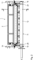
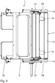
- a dough processing system of which a portioning module 1 of a four-row dough portioning device in the illustrated embodiment is shown in the drawing, is used for portioning and for kneading dough, for example in the production of rolls.
- Corresponding dough processing systems are known from the DE 10 2013 221 230 A1 , of the EP 2 071 955 B1 , of the EP 3 298 900 A. , of the DE 196 40 176 A1 and the EP 0 643 914 A1 ,
- Dough is in a feed hopper 2 (see, for example Fig. 1 ) fillable.
- a bottom-side exit opening 3 (cf. Fig. 3 ) of the feed hopper 2 is connected to a delivery chamber 4, in which a delivery piston (not shown in the drawing) runs.
- the feed piston represents a dough feed device for the dough processing system.
- the dough processing system is designed in several rows overall and has a corresponding plurality of portioning chambers 5 for presetting a portioned amount of dough in each case.
- a total of four are perpendicular to the plane of the drawing, for example Fig. 1 and 3
- Portioning chambers 5 of this type arranged next to one another.
- coat walls 6 of the portioning chambers 5 are formed in a portioning cylinder 7 which, driven by a swivel drive (not shown in detail), can be swiveled about a swivel axis which is perpendicular to the plane of the drawing Fig. 1 and 3 is arranged.
- the portioning cylinder 7 is also referred to as a rotary slide valve. In the Fig. 1 and 3 the portioning cylinder 7 is in a measuring swivel position in which the portioning chambers 5 are aligned with the conveying space 4 and are in dough conveying connection with the latter.
- a measuring piston 8 is arranged in each of the portioning chambers 5.
- the respective measuring piston 8 has an oval piston cross section. Alternatively, a piston cross section of the measuring piston can also be circular.
- the respective measuring piston 8 is in the portioning chamber 5 assigned to it between a retracted measuring position, which is in the Fig. 3 is shown, and an extended ejection position stroke. In the ejection position, an end face piston surface of the respective measuring piston 8 is aligned with a swivel guide wall 9, which at the same time forms a transition between the portioning cylinder 7 and a housing 10 of the portioning module 1.
- the measuring pistons 8 can be made of plastic.
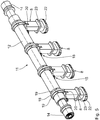
- a drive unit 11 which has a control component designed as a control roller 12, is used to shift the measuring pistons 8 from the measuring position into the ejection position.
- the dough portioning device is designed such that the measuring pistons 8 are shifted from the ejection position into the measuring position exclusively via a delivery pressure exerted on the measuring pistons 8 by the supplied dough.
- the control roller 12 has a longitudinal extent perpendicular to the plane of the drawing Fig. 1 and 3 ,
- the control roller 12 is connected to all measuring pistons 8 for transmitting a tensile force from the control roller 12 to the measuring pistons 8.
- the tensile force transmission means that all the measuring pistons 8 are moved via the control roller 12 during the stroke displacement from the ejection position into the measuring position into the same relative end position in the measuring position in relation to the respective portioning chamber 5. Differences between managers of a guide of the respective measuring piston in the associated portioning chamber 5, caused for example by dough remnants, then do not lead to any positional deviations when the measuring position is reached in comparison between the different measuring pistons 8 of the dough portioning device.
- all measuring pistons 8 therefore specify exactly the same volume within the portioning chamber 5 due to this transmission of tensile force and thus exactly the same portion of dough in each row of the dough portioning device.
- Relative quantity deviations between the dough portions, which are specified via the different rows of the dough portioning device, that is to say via the different measuring pistons 8, can be less than 2%, less than 1% and can also be less than 0.5%.
- the drive unit 11 also includes at least one control cam 13 (cf. 1 to 4 ), which cooperates with the control roller 12.
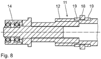
- the control cam 13 is designed in two parts and interacts with opposite free axial control sections 14 of the control roller 12.
- the end portions 14 are rotatably supported relative to the other control roller 12, such as the Fig. 8 represents.
- the connecting unit 15 has an eyelet / bolt connection with an eyelet 16 through which a connecting bolt 17 is guided.
- the eyelet 16 is integrally formed on an annular collar 18 of the respective connecting unit 15, which in turn surrounds the control roller 12.
- An axial position of the respective annular collar 18 on the control roller 12 is fixed via two fixing rings 19, which each hold the annular collar 8 of the respective connecting unit 15 between them and which likewise surround the control roller 12.
- the respective measuring piston 8 has a fork recess 20, into which the eyelet 16 of the annular collar 18 is immersed. In alignment with one eye of the eye 16, through openings 21 are made in this free end, which receive the eye of the eye 16 between them.
- the connecting bolt 17 is passed through the two through openings 21 of the measuring piston 8 and the intermediate eye of the eyelet 16 to create the connection transmitting the tensile force between the respective measuring piston 8 and the control roller 12.
- This eyelet / bolt connection of the connecting unit 15 results in a pivoting degree of freedom of the connection about the axis of the connecting bolt 17. Such a degree of pivoting freedom between the respective measuring piston 8 and the control roller 12 can prevent canting when the measuring piston 8 is guided.
- a diameter of the portioning cylinder 7 is in the Fig. 3 highlighted at D.
- the respective measuring piston 8 is guided over two axially spaced guide surfaces 22, 23 in the associated portioning chambers 5, namely on the jacket walls 6.
- An axial distance A of the guide surfaces 22, 23 (cf. Fig. 7 ), ie an effective axial guide surface extension of the measuring piston 8, is less than a third of the diameter D of the portioning cylinder 7.
- the respective measuring piston 8 can also have exactly one guide surface. For the axial extent of such a single guide surface, what was stated above for the axial spacing of the guide surfaces then applies.
- the stroke movement of the measuring piston between the measuring position and the ejection position is guided by a two-part guide fork 24.
- the control roller 12 runs in the guide fork 24.
- the control roller 12 lies in the measuring position of the measuring piston 8, as in FIG Fig. 3 shown near a free end of the guide fork 24th
- the dough pressure which is generated by the dough conveying from the delivery chamber 4 into the portioning chamber 5, ensures that the measuring pistons 8, which are initially in the ejection position, follow the dough pressure into the measuring position, for example Fig. 3 be transferred.
- the respective measuring piston 8 is in thrust connection with the control roller 12 via a stamp surface 25. This push connection ensures that the control roller 12 in the in the Fig. 3 shown measurement position is shifted in the region of the free end of the guide fork 24.
- the train connection via the respective connecting units 15 between the control roller 12 and all the measuring pistons 8 ensures that all measuring pistons 8 assume exactly the same position as far as the relative positioning within the respective portioning chamber 5 is concerned, regardless of how smoothly or stiffly the guidance is the guide surfaces 22, 23 of the individual volumetric flasks 8 take place.
- the portioning cylinder 7 After reaching the measuring position, the portioning cylinder 7 is moved out of the measuring pivot position in the Fig. 3 counterclockwise in the ejection swivel position.
- the measuring pistons 8 are then transferred from the measuring position, driven by the drive unit 11, with the control roller 12 and the control cam 13, to the ejection position.
- the dough portion present in the portioning chamber 5 up to this point is transferred to a downstream processing unit of the dough processing system.
Landscapes
- Life Sciences & Earth Sciences (AREA)
- Engineering & Computer Science (AREA)
- Food Science & Technology (AREA)
- Manufacturing And Processing Devices For Dough (AREA)
Priority Applications (1)
| Application Number | Priority Date | Filing Date | Title |
|---|---|---|---|
| PL19176854T PL3581029T3 (pl) | 2018-06-13 | 2019-05-28 | Urządzenie do porcjowania ciasta |
Applications Claiming Priority (1)
| Application Number | Priority Date | Filing Date | Title |
|---|---|---|---|
| DE202018103311.5U DE202018103311U1 (de) | 2018-06-13 | 2018-06-13 | Teigportioniervorrichtung |
Publications (4)
| Publication Number | Publication Date |
|---|---|
| EP3581029A2 true EP3581029A2 (fr) | 2019-12-18 |
| EP3581029A3 EP3581029A3 (fr) | 2020-03-25 |
| EP3581029B1 EP3581029B1 (fr) | 2021-04-07 |
| EP3581029B8 EP3581029B8 (fr) | 2021-05-12 |
Family
ID=66668753
Family Applications (1)
| Application Number | Title | Priority Date | Filing Date |
|---|---|---|---|
| EP19176854.8A Active EP3581029B8 (fr) | 2018-06-13 | 2019-05-28 | Dispositif de division en portions de pâte |
Country Status (5)
| Country | Link |
|---|---|
| US (1) | US11076605B2 (fr) |
| EP (1) | EP3581029B8 (fr) |
| DE (1) | DE202018103311U1 (fr) |
| ES (1) | ES2879627T3 (fr) |
| PL (1) | PL3581029T3 (fr) |
Cited By (1)
| Publication number | Priority date | Publication date | Assignee | Title |
|---|---|---|---|---|
| WO2023208727A1 (fr) * | 2022-04-28 | 2023-11-02 | Werner & Pfleiderer Lebensmitteltechnik Gmbh | Appareil de division de pâte en portions |
Citations (5)
| Publication number | Priority date | Publication date | Assignee | Title |
|---|---|---|---|---|
| EP0643914A1 (fr) | 1993-09-21 | 1995-03-22 | Werner & Pfleiderer GmbH | Diviseur de pâte avec chambre de dosage |
| DE19640176A1 (de) | 1996-09-28 | 1998-04-02 | Werner & Pfleiderer Lebensmitt | Teigteil-Maschine |
| EP2071955A2 (fr) | 2007-12-22 | 2009-06-24 | Werner & Pfleiderer Lebensmitteltechnik GmbH | Installation de traitement de pâte |
| DE102013221230A1 (de) | 2013-10-18 | 2015-04-23 | Werner & Pfleiderer Lebensmitteltechnik Gmbh | Drehschieber-Baugruppe für eine Teig-Portioniervorrichtung |
| EP3298900A1 (fr) | 2016-09-27 | 2018-03-28 | Werner & Pfleiderer Lebensmitteltechnik GmbH | Tambour à chambre pour un dispositif de dispositif de pétrissage de la pâte |
Family Cites Families (7)
| Publication number | Priority date | Publication date | Assignee | Title |
|---|---|---|---|---|
| US1080890A (en) * | 1909-12-06 | 1913-12-09 | Champion Machinery Company | Dough-divider. |
| GB191003771A (en) * | 1910-02-15 | 1911-02-15 | John Callow | Improvements in Machines for Dividing Dough and like Plastic Material. |
| ES379968A1 (es) * | 1970-05-22 | 1972-09-01 | Terrent Pardo | Perfeccionamientos introducidos en maquinas dosificadoras de masa panificable. |
| DE3530724C1 (de) * | 1985-08-28 | 1986-07-03 | Werner & Pfleiderer, 7000 Stuttgart | Teigteilmaschine |
| DE4100243C2 (de) * | 1991-01-07 | 1993-12-09 | Werner & Pfleiderer | Teigteilmaschine |
| DE10238707A1 (de) * | 2001-09-10 | 2003-03-27 | Werner & Pfleiderer Lebensmitt | Teigteilmaschine |
| AT519085B1 (de) | 2016-10-07 | 2018-04-15 | Koenig Maschinen Gmbh | Programm-Zyklus gesteuerter Ablauf einer Teiltrommel für Teigteil und Wirkmaschine |
-
2018
- 2018-06-13 DE DE202018103311.5U patent/DE202018103311U1/de active Active
-
2019
- 2019-05-28 PL PL19176854T patent/PL3581029T3/pl unknown
- 2019-05-28 ES ES19176854T patent/ES2879627T3/es active Active
- 2019-05-28 EP EP19176854.8A patent/EP3581029B8/fr active Active
- 2019-06-11 US US16/438,020 patent/US11076605B2/en active Active
Patent Citations (5)
| Publication number | Priority date | Publication date | Assignee | Title |
|---|---|---|---|---|
| EP0643914A1 (fr) | 1993-09-21 | 1995-03-22 | Werner & Pfleiderer GmbH | Diviseur de pâte avec chambre de dosage |
| DE19640176A1 (de) | 1996-09-28 | 1998-04-02 | Werner & Pfleiderer Lebensmitt | Teigteil-Maschine |
| EP2071955A2 (fr) | 2007-12-22 | 2009-06-24 | Werner & Pfleiderer Lebensmitteltechnik GmbH | Installation de traitement de pâte |
| DE102013221230A1 (de) | 2013-10-18 | 2015-04-23 | Werner & Pfleiderer Lebensmitteltechnik Gmbh | Drehschieber-Baugruppe für eine Teig-Portioniervorrichtung |
| EP3298900A1 (fr) | 2016-09-27 | 2018-03-28 | Werner & Pfleiderer Lebensmitteltechnik GmbH | Tambour à chambre pour un dispositif de dispositif de pétrissage de la pâte |
Cited By (1)
| Publication number | Priority date | Publication date | Assignee | Title |
|---|---|---|---|---|
| WO2023208727A1 (fr) * | 2022-04-28 | 2023-11-02 | Werner & Pfleiderer Lebensmitteltechnik Gmbh | Appareil de division de pâte en portions |
Also Published As
| Publication number | Publication date |
|---|---|
| ES2879627T3 (es) | 2021-11-22 |
| EP3581029B8 (fr) | 2021-05-12 |
| PL3581029T3 (pl) | 2021-10-25 |
| US20190380351A1 (en) | 2019-12-19 |
| US11076605B2 (en) | 2021-08-03 |
| EP3581029B1 (fr) | 2021-04-07 |
| DE202018103311U1 (de) | 2019-09-16 |
| EP3581029A3 (fr) | 2020-03-25 |
Similar Documents
| Publication | Publication Date | Title |
|---|---|---|
| EP2069113B1 (fr) | Dispositif de guidage d'un tuyau souple comprenant au moins une conduite d'alimentation | |
| EP2053300B1 (fr) | Répartiteur d'ouvertures | |
| EP2152443B1 (fr) | Système d'alimentation en lubrifiant et ensemble palier pourvu de ce système | |
| EP0865830A2 (fr) | Dispositif de changement de teinte avec sens de circulation de vernis réversible | |
| DE102016223798B4 (de) | Detektionseinrichtung und Schmierstoffverteiler | |
| EP1656520B1 (fr) | Appareil de lubrification et dispositif de lubrification presentant un tel appareil | |
| EP1631767A1 (fr) | Element distributeur pour des systemes de lubrification | |
| EP3581029A2 (fr) | Dispositif de division en portions de la pâte | |
| DE3008053C2 (de) | Progressiv-Zentralschmieranlage | |
| DE102008011590B3 (de) | Schmiermittelverteiler | |
| DE7531870U (de) | Formschliesseinrichtung fuer giessmaschinen | |
| EP3766351B1 (fr) | Dispositif de portionnement de pâte | |
| DE8516548U1 (de) | Blindnietvorrichtung | |
| DE1525182A1 (de) | Einrichtung zum Fuehren eines beweglichen Organs,insbesondere Lager | |
| EP3449726B1 (fr) | Dispositif de division de la pâte ainsi qu'installation de traitement de la pâte pourvue d'un tel dispositif de division de la pâte | |
| EP2478221A1 (fr) | Système permettant de faire sortir plusieurs masses de matière | |
| DE2447938A1 (de) | Ventileinrichtung | |
| EP1726868B1 (fr) | Dispositif de lubrification compact avec une pompe de graissage et un distributeur progressif | |
| DE19833504A1 (de) | Kunststoffschmelze-Schußkolben | |
| DE102017105013B4 (de) | Tintenstrahldrucker für die Beschriftung von Waren mit einem Schreibkopf, einem Vorratsbehälter und einer Halteeinrichtung | |
| EP3048196A1 (fr) | Barre à passettes d'un métier à tricoter chaîne | |
| DE102006001825B4 (de) | Dosierventileinrichtung | |
| EP1722150B1 (fr) | Dispositif de lubrification | |
| EP0981008A1 (fr) | Repartiteur d'huile | |
| DE102015000902B4 (de) | Ausstoßleitungsanordnung für ein Flaschenaufsatzgerät |
Legal Events
| Date | Code | Title | Description |
|---|---|---|---|
| PUAI | Public reference made under article 153(3) epc to a published international application that has entered the european phase |
Free format text: ORIGINAL CODE: 0009012 |
|
| STAA | Information on the status of an ep patent application or granted ep patent |
Free format text: STATUS: THE APPLICATION HAS BEEN PUBLISHED |
|
| AK | Designated contracting states |
Kind code of ref document: A2 Designated state(s): AL AT BE BG CH CY CZ DE DK EE ES FI FR GB GR HR HU IE IS IT LI LT LU LV MC MK MT NL NO PL PT RO RS SE SI SK SM TR |
|
| AX | Request for extension of the european patent |
Extension state: BA ME |
|
| PUAL | Search report despatched |
Free format text: ORIGINAL CODE: 0009013 |
|
| AK | Designated contracting states |
Kind code of ref document: A3 Designated state(s): AL AT BE BG CH CY CZ DE DK EE ES FI FR GB GR HR HU IE IS IT LI LT LU LV MC MK MT NL NO PL PT RO RS SE SI SK SM TR |
|
| AX | Request for extension of the european patent |
Extension state: BA ME |
|
| RIC1 | Information provided on ipc code assigned before grant |
Ipc: A21C 5/04 20060101AFI20200220BHEP |
|
| STAA | Information on the status of an ep patent application or granted ep patent |
Free format text: STATUS: REQUEST FOR EXAMINATION WAS MADE |
|
| 17P | Request for examination filed |
Effective date: 20200721 |
|
| RBV | Designated contracting states (corrected) |
Designated state(s): AL AT BE BG CH CY CZ DE DK EE ES FI FR GB GR HR HU IE IS IT LI LT LU LV MC MK MT NL NO PL PT RO RS SE SI SK SM TR |
|
| GRAP | Despatch of communication of intention to grant a patent |
Free format text: ORIGINAL CODE: EPIDOSNIGR1 |
|
| STAA | Information on the status of an ep patent application or granted ep patent |
Free format text: STATUS: GRANT OF PATENT IS INTENDED |
|
| INTG | Intention to grant announced |
Effective date: 20201105 |
|
| GRAS | Grant fee paid |
Free format text: ORIGINAL CODE: EPIDOSNIGR3 |
|
| GRAA | (expected) grant |
Free format text: ORIGINAL CODE: 0009210 |
|
| STAA | Information on the status of an ep patent application or granted ep patent |
Free format text: STATUS: THE PATENT HAS BEEN GRANTED |
|
| AK | Designated contracting states |
Kind code of ref document: B1 Designated state(s): AL AT BE BG CH CY CZ DE DK EE ES FI FR GB GR HR HU IE IS IT LI LT LU LV MC MK MT NL NO PL PT RO RS SE SI SK SM TR |
|
| REG | Reference to a national code |
Ref country code: GB Ref legal event code: FG4D Free format text: NOT ENGLISH |
|
| REG | Reference to a national code |
Ref country code: AT Ref legal event code: REF Ref document number: 1378503 Country of ref document: AT Kind code of ref document: T Effective date: 20210415 Ref country code: CH Ref legal event code: PK Free format text: BERICHTIGUNG B8 Ref country code: CH Ref legal event code: EP |
|
| REG | Reference to a national code |
Ref country code: DE Ref legal event code: R081 Ref document number: 502019001163 Country of ref document: DE Owner name: BACKNET GMBH, DE Free format text: FORMER OWNER: WERNER & PFLEIDERER LEBENSMITTELTECHNIK GMBH, 91550 DINKELSBUEHL, DE |
|
| REG | Reference to a national code |
Ref country code: DE Ref legal event code: R096 Ref document number: 502019001163 Country of ref document: DE |
|
| RAP2 | Party data changed (patent owner data changed or rights of a patent transferred) |
Owner name: BACKNET GMBH |
|
| REG | Reference to a national code |
Ref country code: IE Ref legal event code: FG4D Free format text: LANGUAGE OF EP DOCUMENT: GERMAN |
|
| REG | Reference to a national code |
Ref country code: LT Ref legal event code: MG9D |
|
| REG | Reference to a national code |
Ref country code: SK Ref legal event code: T3 Ref document number: E 37488 Country of ref document: SK |
|
| REG | Reference to a national code |
Ref country code: NL Ref legal event code: MP Effective date: 20210407 |
|
| PG25 | Lapsed in a contracting state [announced via postgrant information from national office to epo] |
Ref country code: NL Free format text: LAPSE BECAUSE OF FAILURE TO SUBMIT A TRANSLATION OF THE DESCRIPTION OR TO PAY THE FEE WITHIN THE PRESCRIBED TIME-LIMIT Effective date: 20210407 Ref country code: HR Free format text: LAPSE BECAUSE OF FAILURE TO SUBMIT A TRANSLATION OF THE DESCRIPTION OR TO PAY THE FEE WITHIN THE PRESCRIBED TIME-LIMIT Effective date: 20210407 Ref country code: LT Free format text: LAPSE BECAUSE OF FAILURE TO SUBMIT A TRANSLATION OF THE DESCRIPTION OR TO PAY THE FEE WITHIN THE PRESCRIBED TIME-LIMIT Effective date: 20210407 Ref country code: FI Free format text: LAPSE BECAUSE OF FAILURE TO SUBMIT A TRANSLATION OF THE DESCRIPTION OR TO PAY THE FEE WITHIN THE PRESCRIBED TIME-LIMIT Effective date: 20210407 Ref country code: BG Free format text: LAPSE BECAUSE OF FAILURE TO SUBMIT A TRANSLATION OF THE DESCRIPTION OR TO PAY THE FEE WITHIN THE PRESCRIBED TIME-LIMIT Effective date: 20210707 |
|
| REG | Reference to a national code |
Ref country code: ES Ref legal event code: FG2A Ref document number: 2879627 Country of ref document: ES Kind code of ref document: T3 Effective date: 20211122 |
|
| PG25 | Lapsed in a contracting state [announced via postgrant information from national office to epo] |
Ref country code: IS Free format text: LAPSE BECAUSE OF FAILURE TO SUBMIT A TRANSLATION OF THE DESCRIPTION OR TO PAY THE FEE WITHIN THE PRESCRIBED TIME-LIMIT Effective date: 20210807 Ref country code: GR Free format text: LAPSE BECAUSE OF FAILURE TO SUBMIT A TRANSLATION OF THE DESCRIPTION OR TO PAY THE FEE WITHIN THE PRESCRIBED TIME-LIMIT Effective date: 20210708 Ref country code: NO Free format text: LAPSE BECAUSE OF FAILURE TO SUBMIT A TRANSLATION OF THE DESCRIPTION OR TO PAY THE FEE WITHIN THE PRESCRIBED TIME-LIMIT Effective date: 20210707 Ref country code: LV Free format text: LAPSE BECAUSE OF FAILURE TO SUBMIT A TRANSLATION OF THE DESCRIPTION OR TO PAY THE FEE WITHIN THE PRESCRIBED TIME-LIMIT Effective date: 20210407 Ref country code: RS Free format text: LAPSE BECAUSE OF FAILURE TO SUBMIT A TRANSLATION OF THE DESCRIPTION OR TO PAY THE FEE WITHIN THE PRESCRIBED TIME-LIMIT Effective date: 20210407 Ref country code: PT Free format text: LAPSE BECAUSE OF FAILURE TO SUBMIT A TRANSLATION OF THE DESCRIPTION OR TO PAY THE FEE WITHIN THE PRESCRIBED TIME-LIMIT Effective date: 20210809 Ref country code: SE Free format text: LAPSE BECAUSE OF FAILURE TO SUBMIT A TRANSLATION OF THE DESCRIPTION OR TO PAY THE FEE WITHIN THE PRESCRIBED TIME-LIMIT Effective date: 20210407 |
|
| REG | Reference to a national code |
Ref country code: DE Ref legal event code: R097 Ref document number: 502019001163 Country of ref document: DE |
|
| PG25 | Lapsed in a contracting state [announced via postgrant information from national office to epo] |
Ref country code: LU Free format text: LAPSE BECAUSE OF NON-PAYMENT OF DUE FEES Effective date: 20210528 Ref country code: DK Free format text: LAPSE BECAUSE OF FAILURE TO SUBMIT A TRANSLATION OF THE DESCRIPTION OR TO PAY THE FEE WITHIN THE PRESCRIBED TIME-LIMIT Effective date: 20210407 Ref country code: SM Free format text: LAPSE BECAUSE OF FAILURE TO SUBMIT A TRANSLATION OF THE DESCRIPTION OR TO PAY THE FEE WITHIN THE PRESCRIBED TIME-LIMIT Effective date: 20210407 Ref country code: MC Free format text: LAPSE BECAUSE OF FAILURE TO SUBMIT A TRANSLATION OF THE DESCRIPTION OR TO PAY THE FEE WITHIN THE PRESCRIBED TIME-LIMIT Effective date: 20210407 Ref country code: RO Free format text: LAPSE BECAUSE OF FAILURE TO SUBMIT A TRANSLATION OF THE DESCRIPTION OR TO PAY THE FEE WITHIN THE PRESCRIBED TIME-LIMIT Effective date: 20210407 Ref country code: EE Free format text: LAPSE BECAUSE OF FAILURE TO SUBMIT A TRANSLATION OF THE DESCRIPTION OR TO PAY THE FEE WITHIN THE PRESCRIBED TIME-LIMIT Effective date: 20210407 |
|
| PLBE | No opposition filed within time limit |
Free format text: ORIGINAL CODE: 0009261 |
|
| STAA | Information on the status of an ep patent application or granted ep patent |
Free format text: STATUS: NO OPPOSITION FILED WITHIN TIME LIMIT |
|
| 26N | No opposition filed |
Effective date: 20220110 |
|
| PG25 | Lapsed in a contracting state [announced via postgrant information from national office to epo] |
Ref country code: IE Free format text: LAPSE BECAUSE OF NON-PAYMENT OF DUE FEES Effective date: 20210528 |
|
| PG25 | Lapsed in a contracting state [announced via postgrant information from national office to epo] |
Ref country code: IS Free format text: LAPSE BECAUSE OF FAILURE TO SUBMIT A TRANSLATION OF THE DESCRIPTION OR TO PAY THE FEE WITHIN THE PRESCRIBED TIME-LIMIT Effective date: 20210807 Ref country code: AL Free format text: LAPSE BECAUSE OF FAILURE TO SUBMIT A TRANSLATION OF THE DESCRIPTION OR TO PAY THE FEE WITHIN THE PRESCRIBED TIME-LIMIT Effective date: 20210407 |
|
| PG25 | Lapsed in a contracting state [announced via postgrant information from national office to epo] |
Ref country code: CY Free format text: LAPSE BECAUSE OF FAILURE TO SUBMIT A TRANSLATION OF THE DESCRIPTION OR TO PAY THE FEE WITHIN THE PRESCRIBED TIME-LIMIT Effective date: 20210407 |
|
| PG25 | Lapsed in a contracting state [announced via postgrant information from national office to epo] |
Ref country code: HU Free format text: LAPSE BECAUSE OF FAILURE TO SUBMIT A TRANSLATION OF THE DESCRIPTION OR TO PAY THE FEE WITHIN THE PRESCRIBED TIME-LIMIT; INVALID AB INITIO Effective date: 20190528 |
|
| PG25 | Lapsed in a contracting state [announced via postgrant information from national office to epo] |
Ref country code: MK Free format text: LAPSE BECAUSE OF FAILURE TO SUBMIT A TRANSLATION OF THE DESCRIPTION OR TO PAY THE FEE WITHIN THE PRESCRIBED TIME-LIMIT Effective date: 20210407 |
|
| PG25 | Lapsed in a contracting state [announced via postgrant information from national office to epo] |
Ref country code: MT Free format text: LAPSE BECAUSE OF FAILURE TO SUBMIT A TRANSLATION OF THE DESCRIPTION OR TO PAY THE FEE WITHIN THE PRESCRIBED TIME-LIMIT Effective date: 20210407 |
|
| PGFP | Annual fee paid to national office [announced via postgrant information from national office to epo] |
Ref country code: PL Payment date: 20250418 Year of fee payment: 7 |
|
| PGFP | Annual fee paid to national office [announced via postgrant information from national office to epo] |
Ref country code: ES Payment date: 20250616 Year of fee payment: 7 Ref country code: GB Payment date: 20250522 Year of fee payment: 7 |
|
| PGFP | Annual fee paid to national office [announced via postgrant information from national office to epo] |
Ref country code: BE Payment date: 20250520 Year of fee payment: 7 Ref country code: IT Payment date: 20250530 Year of fee payment: 7 |
|
| PGFP | Annual fee paid to national office [announced via postgrant information from national office to epo] |
Ref country code: FR Payment date: 20250526 Year of fee payment: 7 |
|
| PGFP | Annual fee paid to national office [announced via postgrant information from national office to epo] |
Ref country code: CH Payment date: 20250601 Year of fee payment: 7 |
|
| PGFP | Annual fee paid to national office [announced via postgrant information from national office to epo] |
Ref country code: AT Payment date: 20250424 Year of fee payment: 7 |
|
| PGFP | Annual fee paid to national office [announced via postgrant information from national office to epo] |
Ref country code: SK Payment date: 20250523 Year of fee payment: 7 |
|
| PGFP | Annual fee paid to national office [announced via postgrant information from national office to epo] |
Ref country code: CZ Payment date: 20250515 Year of fee payment: 7 |
|
| PGFP | Annual fee paid to national office [announced via postgrant information from national office to epo] |
Ref country code: DE Payment date: 20250725 Year of fee payment: 7 |
|
| PG25 | Lapsed in a contracting state [announced via postgrant information from national office to epo] |
Ref country code: TR Free format text: LAPSE BECAUSE OF FAILURE TO SUBMIT A TRANSLATION OF THE DESCRIPTION OR TO PAY THE FEE WITHIN THE PRESCRIBED TIME-LIMIT Effective date: 20210407 |