EP3584912B1 - Motor zum antrieb einer linse - Google Patents
Motor zum antrieb einer linse Download PDFInfo
- Publication number
- EP3584912B1 EP3584912B1 EP19189789.1A EP19189789A EP3584912B1 EP 3584912 B1 EP3584912 B1 EP 3584912B1 EP 19189789 A EP19189789 A EP 19189789A EP 3584912 B1 EP3584912 B1 EP 3584912B1
- Authority
- EP
- European Patent Office
- Prior art keywords
- spring
- base
- terminal
- corner
- sections
- Prior art date
- Legal status (The legal status is an assumption and is not a legal conclusion. Google has not performed a legal analysis and makes no representation as to the accuracy of the status listed.)
- Active
Links
Images


Classifications
-
- G—PHYSICS
- G02—OPTICS
- G02B—OPTICAL ELEMENTS, SYSTEMS OR APPARATUS
- G02B7/00—Mountings, adjusting means, or light-tight connections, for optical elements
- G02B7/02—Mountings, adjusting means, or light-tight connections, for optical elements for lenses
- G02B7/023—Mountings, adjusting means, or light-tight connections, for optical elements for lenses permitting adjustment
-
- G—PHYSICS
- G02—OPTICS
- G02B—OPTICAL ELEMENTS, SYSTEMS OR APPARATUS
- G02B7/00—Mountings, adjusting means, or light-tight connections, for optical elements
- G02B7/02—Mountings, adjusting means, or light-tight connections, for optical elements for lenses
- G02B7/026—Mountings, adjusting means, or light-tight connections, for optical elements for lenses using retaining rings or springs
-
- G—PHYSICS
- G02—OPTICS
- G02B—OPTICAL ELEMENTS, SYSTEMS OR APPARATUS
- G02B7/00—Mountings, adjusting means, or light-tight connections, for optical elements
- G02B7/02—Mountings, adjusting means, or light-tight connections, for optical elements for lenses
- G02B7/04—Mountings, adjusting means, or light-tight connections, for optical elements for lenses with mechanism for focusing or varying magnification
- G02B7/08—Mountings, adjusting means, or light-tight connections, for optical elements for lenses with mechanism for focusing or varying magnification adapted to co-operate with a remote control mechanism
-
- G—PHYSICS
- G03—PHOTOGRAPHY; CINEMATOGRAPHY; ANALOGOUS TECHNIQUES USING WAVES OTHER THAN OPTICAL WAVES; ELECTROGRAPHY; HOLOGRAPHY
- G03B—APPARATUS OR ARRANGEMENTS FOR TAKING PHOTOGRAPHS OR FOR PROJECTING OR VIEWING THEM; APPARATUS OR ARRANGEMENTS EMPLOYING ANALOGOUS TECHNIQUES USING WAVES OTHER THAN OPTICAL WAVES; ACCESSORIES THEREFOR
- G03B3/00—Focusing arrangements of general interest for cameras, projectors or printers
- G03B3/10—Power-operated focusing
-
- H—ELECTRICITY
- H02—GENERATION; CONVERSION OR DISTRIBUTION OF ELECTRIC POWER
- H02K—DYNAMO-ELECTRIC MACHINES
- H02K41/00—Propulsion systems in which a rigid body is moved along a path due to dynamo-electric interaction between the body and a magnetic field travelling along the path
- H02K41/02—Linear motors; Sectional motors
- H02K41/035—DC motors; Unipolar motors
- H02K41/0352—Unipolar motors
- H02K41/0354—Lorentz force motors, e.g. voice coil motors
- H02K41/0356—Lorentz force motors, e.g. voice coil motors moving along a straight path
-
- H—ELECTRICITY
- H02—GENERATION; CONVERSION OR DISTRIBUTION OF ELECTRIC POWER
- H02K—DYNAMO-ELECTRIC MACHINES
- H02K5/00—Casings; Enclosures; Supports
-
- H—ELECTRICITY
- H02—GENERATION; CONVERSION OR DISTRIBUTION OF ELECTRIC POWER
- H02K—DYNAMO-ELECTRIC MACHINES
- H02K5/00—Casings; Enclosures; Supports
- H02K5/04—Casings or enclosures characterised by the shape, form or construction thereof
- H02K5/22—Auxiliary parts of casings not covered by groups H02K5/06-H02K5/20, e.g. shaped to form connection boxes or terminal boxes
- H02K5/225—Terminal boxes or connection arrangements
-
- H—ELECTRICITY
- H02—GENERATION; CONVERSION OR DISTRIBUTION OF ELECTRIC POWER
- H02K—DYNAMO-ELECTRIC MACHINES
- H02K2211/00—Specific aspects not provided for in the other groups of this subclass relating to measuring or protective devices or electric components
- H02K2211/03—Machines characterised by circuit boards, e.g. pcb
Definitions
- the present document relates to a motor for driving lenses and a digital apparatus comprising such a motor.
- Each of KR 100 490 253 B1 and WO 2006/085714 A1 relates to a motor for driving lenses, in particular an automatic focus-adjusting device for an optical lens, in which the arrangement of a permanent magnet and the outer size of the device is reduced.
- An upper and a lower spring are provided.
- the lower spring comprises two terminals.
- the two terminals are arranged on diametrically opposite sides of an optical axis.
- JP 2003 207708 A discloses a further motor for driving lenses. Two terminals are arranged on diametrically opposite sides of an optical axis.
- JP 2006 058662 A discloses a lens driving device capable of moderating an impact made when a lens support base collides with a housing.
- An upper and a lower spring is provided in the lens driving device.
- JP 2003 207708 A refers to small-sized lens driving unit.
- a motor for driving lenses of the camera installed in the digital device is also developed and extensively used.
- the motor for driving the lenses adjusts the position of the lenses by using a carrier that moves as current is supplied to/removed from a coil.
- the coil receives external power through a spring electrically connected to both the coil and a main printed circuit board (PCB).
- PCB main printed circuit board
- Embodiments of the present invention provide a motor for driving lenses, capable of minimizing the size thereof while stably supplying current to a coil.
- the invention is as defined in claim 1.
- the motor for driving the lenses according to embodiments of the present invention can minimize the size thereof while stably supplying current to the coil.
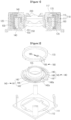
- FIG. 1 is a sectional view showing a motor for driving lenses.
- a coil 160 is fixedly wound around an outer peripheral surface of the carrier 150.
- the coil 160 is spaced apart from the magnet 130 in opposition to the magnet 130.
- electromagnetic force is generated between the coil 160 and the magnet 130, so that the coil 160 is urged upward or downward.
- the carrier 150 is moved up or down, thereby moving the lenses 200.
- a spacer 170 having elasticity is installed between a bottom surface of the yoke 120 and the base 111, and between a top surface of the yoke 120 and the upper cover 115, respectively.
- the spacer 170 has a ring shape.
- the spacer 170 can be compressed and expanded so as to compensate for the tolerance of parts assembled in the case 110 and the tolerance occurring when assembling the parts.
- One end portion and the other end portion of the inner sections 142 and 146 of the spring 140 are exposed out of the carrier 150 so as to connected with the lead wire of the coil 160 and conductive terminals 180, respectively.
Landscapes
- Physics & Mathematics (AREA)
- Engineering & Computer Science (AREA)
- General Physics & Mathematics (AREA)
- Power Engineering (AREA)
- Optics & Photonics (AREA)
- Chemical & Material Sciences (AREA)
- Combustion & Propulsion (AREA)
- Electromagnetism (AREA)
- Lens Barrels (AREA)
Claims (11)
- Motor zum Antreiben einer Linse, der Motor umfassend:eine Basis (111, 611);ein Joch (120), das an der Basis (111, 611) angeordnet ist;einen Magneten (130), der in dem Joch (120) angeordnet ist;einen Abstandshalter (170), der zwischen einer Bodenoberfläche des Jochs (120) und der Basis (111, 611) angebracht ist;einen Träger (150),- der in dem Joch (120) angeordnet ist,- der konfiguriert ist, um sich in einer vertikalen Richtung zu bewegen, und- aus einem oberen Träger (151) und einem unteren Träger (155, 355) besteht, die miteinander gekoppelt sind;eine Spule (160), die an einer äußeren Umfangsoberfläche des Trägers (150) angeordnet ist, während sie dem Magneten (130) zugewandt ist,wobei der Träger (150) konfiguriert ist,- um durch elektromagnetische Kraft nach oben bewegt zu werden; und- um mittels der Feder (140, 340) in seine Ausgangsposition zurückzukehren,wobei Zuleitungsdrähte der Spule (160) mit der Feder (140, 340) verbunden sind, um es externer Leistung zu ermöglichen, über die Feder (140, 340) an die Spule (160) angelegt zu werden,wobei die Feder (140, 340) eine obere Feder, die mit einem oberen Teil des Trägers (150) gekoppelt ist, und eine untere Feder umfasst, die mit einem unteren Teil des Trägers (150) und mit der Basis (111, 611) gekoppelt ist,wobei jede der oberen und der unteren Feder (340) eine erste Feder (341, 441) und eine zweite Feder (345, 445) einschließt, die eine Bogenform aufweisen und voneinander getrennt sind,wobei die erste und die zweite Feder (341, 345; 441, 445) als Ganzes eine Ringform ausbilden, wobei jede der ersten und der zweiten Feder (341, 345; 441, 445) einen inneren Abschnitt (342, 346; 442, 446), einen äußeren Abschnitt (343, 347; 443, 447) und einen Verbindungsabschnitt (344, 348; 444, 448) einschließt,wobei die inneren Abschnitte (342, 346; 442, 446) eine Bogenform aufweisen und innere Umfangsoberflächen davon mit einer äußeren Oberfläche des unteren Trägers (355) einstückig ausgebildet sind,wobei die äußeren Abschnitte (343, 347; 443, 447) eine Bogenform aufweisen und äußere Umfangsoberflächen davon zwischen dem Abstandshalter (170) und der Basis (111, 611) befestigt sind,wobei die Verbindungsabschnitte (344, 348; 444, 448) die inneren Abschnitte (342, 346; 442, 446) mit den äußeren Abschnitten (343, 347; 443, 447) verbinden,wobei erste Endteile (342a, 346a; 442a, 446a) der inneren Abschnitte (342, 346; 442, 446) aus dem unteren Träger (355) freigelegt sind, um es dem Zuleitungsdraht der Spule (150) zu ermöglichen, an die ersten Endteile (342a, 346a; 442a, 446a) gelötet zu werden,wobei erste Endteile (343a, 347a; 443a, 447a) der äußeren Abschnitte (343, 347; 443, 447) der ersten und der zweiten Feder (341, 345; 441, 445) aus dem unteren Träger (355) freigelegt sind und Biegeabschnitte (343aa, 347aa; 443aa, 447aa), die nach unten gebogen sind, bereitgestellt sind, um mit einer Hauptleiterplatte (Haupt-PCB) des Motors verbunden zu werden;wobei die Basis (111, 611) ferner eine erste Seitenoberfläche, eine zweite Seitenoberfläche, eine dritte Seitenoberfläche gegenüber der ersten Seitenoberfläche, eine vierte Seitenoberfläche gegenüber der zweiten Seitenoberfläche, eine erste Ecke, wo die erste und die zweite Seitenoberfläche zusammentreffen, eine zweite Ecke, wo die zweite und die dritte Seitenoberfläche zusammentreffen, eine dritte Ecke, wo die dritte und die vierte Seitenoberfläche zusammentreffen und gegenüber der ersten Ecke, und eine vierte Ecke, wo die vierte und die erste Seitenoberfläche zusammentreffen und gegenüber der zweiten Ecke, umfasst,wobei die Basis (111, 611) ferner zwei Stützschlitze (612) umfasst, die an der ersten Seitenoberfläche ausgebildet sind, wobei die zwei Stützschlitze (612) einen ersten Stützschlitz und einen zweiten Stützschlitz einschließen, und wobei der erste Stützschlitz von der ersten Seitenoberfläche nach innen vertieft ist und der zweite Stützschlitz von der ersten Seitenoberfläche nach innen vertieft ist,wobei zwei Anschlüsse (680) mit der Hauptleiterplatte (Haupt-PCB) verbunden sind und mit den Stützschlitzen (612) gekoppelt sind, die in der Basis (111, 611) vertieft sind,wobei ein erster Anschluss der zwei Anschlüsse (680) mit dem ersten Stützschlitz gekoppelt ist und ein zweiter Anschluss der zwei Anschlüsse (680) mit dem zweiten Stützschlitz der Basis (111, 611) gekoppelt ist,wobei der erste Anschluss mit einem der Biegeabschnitte (343aa, 347aa; 443aa, 447aa) der ersten Feder (341, 441) elektrisch verbunden ist und der zweite Anschluss mit dem anderen der Biegeabschnitte (343aa, 347aa; 443aa, 447aa) der zweiten Feder (345,445) elektrisch verbunden ist, undwobei der erste Anschluss näher an der ersten Ecke der Basis (111, 611) als an der vierten Ecke liegt und der zweite Anschluss näher an der vierten Ecke der Basis (111, 611) als an der ersten Ecke liegt, wobei, in einer horizontalen Richtung, die Entfernung zwischen dem ersten Anschluss und dem zweiten Anschluss kürzer als die Entfernung zwischen dem ersten Anschluss und der ersten Ecke ist.
- Motor nach Anspruch 1, wobei das Joch (120) zwischen der ersten Ecke und der dritten Ecke und zwischen der zweiten Ecke und der vierten Ecke angeordnet ist.
- Motor nach einem der Ansprüche 1 bis 2, wobei die erste Seitenoberfläche eine flache Oberfläche zwischen dem ersten Stützschlitz und dem zweiten Stützschlitz umfasst, und
wobei der erste Stützschlitz von der flachen Oberfläche nach innen vertieft ist und der zweite Stützschlitz von der flachen Oberfläche nach innen vertieft ist. - Motor nach einem der Ansprüche 1 bis 3, wobei der erste Anschluss dem ersten Stützschlitz der Basis (111, 611) in der horizontaler Richtung zugewandt ist,wobei der zweite Anschluss dem zweiten Stützschlitz der Basis (111, 611) in der horizontalen Richtung zugewandt ist undwobei der erste Anschluss und der zweite Anschluss von der ersten Seitenoberfläche der Basis (111, 611) nach innen angeordnet sind.
- Motor nach Anspruch 1, wobei die zwei Anschlüsse (680) ein Stück umfassen, das sich von einem oberen Teil der ersten Seitenoberfläche zu einem unteren Teil der ersten Seitenoberfläche nach unten erstreckt.
- Motor nach einem der Ansprüche 1 bis 5, wobei der erste Anschluss eine erste Oberfläche umfasst, die aus der Basis (111, 611) freigelegt ist, und der zweite Anschluss eine zweite Oberfläche umfasst, die aus der Basis (111, 611) freigelegt ist, und
wobei die erste Oberfläche des ersten Anschlusses und die zweite Oberfläche des zweiten Anschlusses auf einer gleichen Ebene angeordnet sind. - Motor nach einem der Ansprüche 1 bis 6, wobei jeder des ersten und des zweiten Anschlusses nach unten unterhalb eines Teils der Basis (111, 611) vorsteht.
- Motor nach einem der Ansprüche 1 bis 7,wobei der innere Abschnitt (342, 346; 442, 446) der ersten Feder mit einem Endteil der Spule (160) verbunden ist undwobei der innere Abschnitt (342, 346; 442, 446) der zweiten Feder mit dem anderen Endteil der Spule (160) verbunden ist.
- Motor nach einem der Ansprüche 1 bis 8, wobei der äußere Abschnitt (343, 3447; 443, 447) der ersten Feder und der äußere Abschnitt (343, 3447; 443, 447) der zweiten Feder auf einer gleichen horizontalen Ebene angeordnet sind.
- Motor nach einem der Ansprüche 1 bis 9, wobei das Joch (120) eine obere Oberfläche umfasst, die mit einer Öffnung und einer Seitenoberfläche ausgebildet ist, und
wobei eine obere Oberfläche des Magneten (130) unter der oberen Oberfläche des Jochs (120) angeordnet ist und eine Seitenoberfläche des Magneten (130) der Seitenoberfläche des Jochs (120) zugewandt ist. - Digitale Einrichtung, umfassend den Motor nach einem der Ansprüche 1 bis 10.
Applications Claiming Priority (6)
| Application Number | Priority Date | Filing Date | Title |
|---|---|---|---|
| KR1020060042643A KR100862303B1 (ko) | 2006-05-11 | 2006-05-11 | 렌즈 구동용 모터 |
| KR1020060043024A KR100862304B1 (ko) | 2006-05-12 | 2006-05-12 | 렌즈 구동용 모터 |
| KR1020060044203A KR100888240B1 (ko) | 2006-05-17 | 2006-05-17 | 렌즈 구동용 모터 |
| EP07746475A EP2016668B1 (de) | 2006-05-11 | 2007-05-10 | Motor zum antreiben von linsen |
| EP12196142.9A EP2568325B1 (de) | 2006-05-11 | 2007-05-10 | Motor zum Linsenantrieb |
| PCT/KR2007/002322 WO2007133013A1 (en) | 2006-05-11 | 2007-05-10 | Motor for driving lenses |
Related Parent Applications (3)
| Application Number | Title | Priority Date | Filing Date |
|---|---|---|---|
| EP07746475A Division EP2016668B1 (de) | 2006-05-11 | 2007-05-10 | Motor zum antreiben von linsen |
| EP12196142.9A Division EP2568325B1 (de) | 2006-05-11 | 2007-05-10 | Motor zum Linsenantrieb |
| EP12196142.9A Division-Into EP2568325B1 (de) | 2006-05-11 | 2007-05-10 | Motor zum Linsenantrieb |
Publications (3)
| Publication Number | Publication Date |
|---|---|
| EP3584912A2 EP3584912A2 (de) | 2019-12-25 |
| EP3584912A3 EP3584912A3 (de) | 2020-05-06 |
| EP3584912B1 true EP3584912B1 (de) | 2025-02-26 |
Family
ID=38694078
Family Applications (4)
| Application Number | Title | Priority Date | Filing Date |
|---|---|---|---|
| EP19189789.1A Active EP3584912B1 (de) | 2006-05-11 | 2007-05-10 | Motor zum antrieb einer linse |
| EP12196142.9A Active EP2568325B1 (de) | 2006-05-11 | 2007-05-10 | Motor zum Linsenantrieb |
| EP13180743.0A Active EP2665165B1 (de) | 2006-05-11 | 2007-05-10 | Motor zum Antrieb eines Linsensatzes |
| EP07746475A Active EP2016668B1 (de) | 2006-05-11 | 2007-05-10 | Motor zum antreiben von linsen |
Family Applications After (3)
| Application Number | Title | Priority Date | Filing Date |
|---|---|---|---|
| EP12196142.9A Active EP2568325B1 (de) | 2006-05-11 | 2007-05-10 | Motor zum Linsenantrieb |
| EP13180743.0A Active EP2665165B1 (de) | 2006-05-11 | 2007-05-10 | Motor zum Antrieb eines Linsensatzes |
| EP07746475A Active EP2016668B1 (de) | 2006-05-11 | 2007-05-10 | Motor zum antreiben von linsen |
Country Status (4)
| Country | Link |
|---|---|
| US (9) | US8068295B2 (de) |
| EP (4) | EP3584912B1 (de) |
| TW (2) | TWI512386B (de) |
| WO (1) | WO2007133013A1 (de) |
Families Citing this family (23)
| Publication number | Priority date | Publication date | Assignee | Title |
|---|---|---|---|---|
| EP3584912B1 (de) | 2006-05-11 | 2025-02-26 | Lg Innotek Co. Ltd | Motor zum antrieb einer linse |
| TWI409567B (zh) * | 2008-02-01 | 2013-09-21 | Hon Hai Prec Ind Co Ltd | 奈米碳管驅動器及採用其之鏡頭模組、相機模組 |
| EP2096477A1 (de) * | 2008-02-28 | 2009-09-02 | Mitsumi Electric Co., Ltd. | Linsensteuervorrichtung und Kameramodul |
| KR100941436B1 (ko) * | 2008-04-16 | 2010-02-11 | 엘지이노텍 주식회사 | 렌즈 구동용 모터 |
| JP2011164505A (ja) * | 2010-02-15 | 2011-08-25 | Panasonic Corp | レンズ駆動用装置 |
| KR101741817B1 (ko) | 2010-07-19 | 2017-05-31 | 엘지이노텍 주식회사 | 보이스 코일 모터 |
| US8836177B2 (en) | 2010-07-30 | 2014-09-16 | Lg Innotek Co., Ltd. | Voice coil motor |
| JP6030287B2 (ja) * | 2011-06-08 | 2016-11-24 | 日本電産サンキョー株式会社 | レンズ駆動装置およびレンズ駆動装置の製造方法 |
| KR101971639B1 (ko) | 2011-11-30 | 2019-08-13 | 엘지이노텍 주식회사 | 보이스 코일 모터 |
| TWI537625B (zh) * | 2011-12-29 | 2016-06-11 | 鴻海精密工業股份有限公司 | 鏡頭模組 |
| JP5884976B2 (ja) * | 2012-01-31 | 2016-03-15 | ミツミ電機株式会社 | レンズホルダ駆動装置 |
| JP2015092213A (ja) * | 2013-11-08 | 2015-05-14 | 惠州市大亜湾永昶電子工業有限公司 | レンズ駆動装置 |
| CN104284066B (zh) * | 2014-10-08 | 2018-03-30 | 信利光电股份有限公司 | 可调镜头倾斜度的摄像模组 |
| CN104270556A (zh) * | 2014-10-08 | 2015-01-07 | 信利光电股份有限公司 | 摄像模组 |
| KR102651623B1 (ko) * | 2016-05-30 | 2024-03-27 | 엘지이노텍 주식회사 | 렌즈 구동 장치, 카메라 모듈 및 광학기기 |
| US11774703B2 (en) * | 2017-08-30 | 2023-10-03 | Lg Innotek Co., Ltd. | Lens driving device, and camera module and optical device including same |
| KR102792544B1 (ko) | 2018-10-19 | 2025-04-08 | 엘지이노텍 주식회사 | 카메라 액츄에이터 및 이를 포함하는 카메라 모듈 |
| US11586006B2 (en) * | 2018-12-27 | 2023-02-21 | Tdk Taiwan Corp. | Reflective element driving module |
| WO2020149383A1 (ja) * | 2019-01-16 | 2020-07-23 | 株式会社ミツバ | モータユニット及び液体供給装置 |
| DE102019216283A1 (de) * | 2019-10-23 | 2021-04-29 | Robert Bosch Gmbh | Verfahren zur Herstellung eines Kameramoduls, Kameramodul |
| CN110908064B (zh) * | 2019-12-25 | 2025-02-28 | 新思考电机有限公司 | 三角形透镜驱动马达及具备它的照相装置与电子设备 |
| TWI731724B (zh) | 2020-06-20 | 2021-06-21 | 大陽科技股份有限公司 | 攝影鏡頭、鏡頭驅動模組與電子裝置 |
| CN219065853U (zh) * | 2021-10-22 | 2023-05-23 | 台湾东电化股份有限公司 | 驱动机构 |
Family Cites Families (45)
| Publication number | Priority date | Publication date | Assignee | Title |
|---|---|---|---|---|
| JPS6095735A (ja) * | 1983-10-31 | 1985-05-29 | Hitachi Ltd | 対物レンズ駆動装置 |
| JPS60239939A (ja) * | 1984-05-14 | 1985-11-28 | Hitachi Ltd | 対物レンズ駆動装置 |
| JPH02203431A (ja) | 1989-02-02 | 1990-08-13 | Teac Corp | 対物レンズ駆動装置及びその製造方法 |
| JPH0863769A (ja) * | 1994-06-17 | 1996-03-08 | Sony Corp | 対物レンズ駆動装置及びその製造方法 |
| US6208809B1 (en) | 1998-07-17 | 2001-03-27 | Fuji Photo Film Co., Ltd. | Camera with motor-driven lens barrel |
| JP2002231375A (ja) * | 2001-01-30 | 2002-08-16 | Yazaki Corp | 補機モジュールの封止構造 |
| JP2003207708A (ja) * | 2002-01-11 | 2003-07-25 | Shicoh Eng Co Ltd | レンズ駆動装置 |
| JP2003295033A (ja) * | 2002-04-02 | 2003-10-15 | Shicoh Eng Co Ltd | レンズ駆動装置 |
| JP4324368B2 (ja) * | 2002-10-18 | 2009-09-02 | シコー株式会社 | レンズ駆動装置 |
| JP3725118B2 (ja) * | 2002-11-21 | 2005-12-07 | 三菱電機株式会社 | 対物レンズ駆動装置 |
| JP2004197073A (ja) * | 2002-12-02 | 2004-07-15 | Sankyo Seiki Mfg Co Ltd | 電着材料、およびモータ、並びにレンズ駆動装置 |
| JP2004343895A (ja) * | 2003-05-15 | 2004-12-02 | Nidec Copal Corp | ステッピングモータ及びレンズ駆動装置 |
| TWI274928B (en) | 2003-09-22 | 2007-03-01 | Alps Electric Co Ltd | Focal point adjustment device |
| JP2005128405A (ja) * | 2003-10-27 | 2005-05-19 | Shicoh Eng Co Ltd | レンズ駆動装置 |
| JP4360896B2 (ja) * | 2003-12-15 | 2009-11-11 | シャープ株式会社 | オートフォーカス装置 |
| EP1560066B1 (de) | 2004-01-20 | 2008-03-19 | Samsung Electronics Co., Ltd. | Motorisierte Blende für eine Kamera |
| KR100565801B1 (ko) * | 2004-01-20 | 2006-03-29 | 삼성전자주식회사 | 렌즈셔터 구동용 스테핑모터 및 렌즈셔터 구동장치 및이를 가지는 렌즈유닛 |
| WO2005084013A1 (en) * | 2004-02-27 | 2005-09-09 | Ct Electronics Co., Ltd. | Mini camera device for telecommunication devices |
| JP3782088B2 (ja) * | 2004-03-15 | 2006-06-07 | シャープ株式会社 | 板バネ及びそれを備えたレンズアクチュエータ |
| US7285879B2 (en) * | 2004-08-09 | 2007-10-23 | Mitsumi Electric Co., Ltd. | Autofocus actuator |
| JP2006058662A (ja) * | 2004-08-20 | 2006-03-02 | Shicoh Eng Co Ltd | レンズ駆動装置及び小型カメラ |
| TWI253517B (en) * | 2004-10-11 | 2006-04-21 | Arima Computer Corp | A camera lens drive mechanism |
| KR100490253B1 (ko) * | 2004-10-15 | 2005-05-18 | 주식회사 모비너스 | 소형 광학렌즈의 자동초점 조절장치 |
| JP2005037971A (ja) | 2004-11-01 | 2005-02-10 | Pentax Corp | レンズ鏡筒 |
| JP4415268B2 (ja) | 2005-02-15 | 2010-02-17 | ソニー株式会社 | レンズユニット及び撮像装置 |
| TWI298805B (en) | 2005-02-15 | 2008-07-11 | Sony Corp | Lens unit and imaging apparatus |
| JP4419081B2 (ja) | 2005-03-09 | 2010-02-24 | ソニー株式会社 | レンズユニット及び撮像装置 |
| JP4626346B2 (ja) * | 2005-03-10 | 2011-02-09 | ミツミ電機株式会社 | オートフォーカス用アクチュエータ |
| JP4682653B2 (ja) * | 2005-03-14 | 2011-05-11 | ミツミ電機株式会社 | オートフォーカス用アクチュエータ |
| TWI274926B (en) * | 2005-05-27 | 2007-03-01 | Powergate Optical Inc | A suspension apparatus for auto-focus lens device and a method for fabricating the same |
| US7298562B2 (en) * | 2005-09-02 | 2007-11-20 | Nidec Sankyo Corporation | Lens drive unit |
| JP4517297B2 (ja) * | 2005-10-17 | 2010-08-04 | ソニー株式会社 | レンズユニット及び撮像装置 |
| JP4551863B2 (ja) * | 2005-10-21 | 2010-09-29 | シコー株式会社 | レンズ駆動装置 |
| KR100836776B1 (ko) * | 2005-12-02 | 2008-06-10 | 엘지이노텍 주식회사 | 렌즈 구동 모터용 탄성부재 및 렌즈 구동용 모터 |
| KR100862303B1 (ko) | 2006-05-11 | 2008-10-13 | 엘지이노텍 주식회사 | 렌즈 구동용 모터 |
| KR100888240B1 (ko) | 2006-05-17 | 2009-03-12 | 엘지이노텍 주식회사 | 렌즈 구동용 모터 |
| EP3584912B1 (de) * | 2006-05-11 | 2025-02-26 | Lg Innotek Co. Ltd | Motor zum antrieb einer linse |
| KR100862304B1 (ko) | 2006-05-12 | 2008-10-13 | 엘지이노텍 주식회사 | 렌즈 구동용 모터 |
| JP4942187B2 (ja) * | 2006-06-30 | 2012-05-30 | シコー株式会社 | レンズ駆動装置、カメラ及びカメラ付き携帯電話 |
| JP4725467B2 (ja) * | 2006-09-14 | 2011-07-13 | ミツミ電機株式会社 | カメラモジュール |
| US7400463B1 (en) * | 2007-03-06 | 2008-07-15 | Tdk Taiwan Corp. | Miniature lens focusing mechanism |
| JP2008268404A (ja) * | 2007-04-18 | 2008-11-06 | Tricore Corp | ボイスコイル型のレンズ駆動装置 |
| JP2008268474A (ja) * | 2007-04-19 | 2008-11-06 | Tricore Corp | ボイスコイル型のレンズ駆動装置 |
| JP2008268475A (ja) * | 2007-04-19 | 2008-11-06 | Tricore Corp | ボイスコイル型のレンズ駆動装置 |
| CN201373938Y (zh) * | 2009-02-03 | 2009-12-30 | 力相光学股份有限公司 | 微小型磁浮式镜头驱动装置 |
-
2007
- 2007-05-10 EP EP19189789.1A patent/EP3584912B1/de active Active
- 2007-05-10 EP EP12196142.9A patent/EP2568325B1/de active Active
- 2007-05-10 EP EP13180743.0A patent/EP2665165B1/de active Active
- 2007-05-10 WO PCT/KR2007/002322 patent/WO2007133013A1/en not_active Ceased
- 2007-05-10 US US11/913,307 patent/US8068295B2/en active Active
- 2007-05-10 EP EP07746475A patent/EP2016668B1/de active Active
- 2007-05-11 TW TW102116185A patent/TWI512386B/zh active
- 2007-05-11 TW TW096116954A patent/TWI397764B/zh active
-
2011
- 2011-10-17 US US13/274,979 patent/US8659844B2/en active Active
-
2013
- 2013-07-30 US US13/954,535 patent/US8922919B2/en active Active
-
2014
- 2014-08-28 US US14/472,111 patent/US9891403B2/en active Active
-
2018
- 2018-01-11 US US15/868,606 patent/US10746953B2/en active Active
-
2020
- 2020-07-06 US US16/921,294 patent/US11415772B2/en active Active
-
2022
- 2022-07-11 US US17/811,722 patent/US11698508B2/en active Active
-
2023
- 2023-05-30 US US18/325,581 patent/US12066685B2/en active Active
-
2024
- 2024-07-18 US US18/776,708 patent/US20240369802A1/en active Pending
Also Published As
| Publication number | Publication date |
|---|---|
| EP2016668A4 (de) | 2010-07-07 |
| EP2665165A1 (de) | 2013-11-20 |
| US8068295B2 (en) | 2011-11-29 |
| US8922919B2 (en) | 2014-12-30 |
| TW201335693A (zh) | 2013-09-01 |
| EP2016668B1 (de) | 2013-02-20 |
| US12066685B2 (en) | 2024-08-20 |
| US8659844B2 (en) | 2014-02-25 |
| US20180136432A1 (en) | 2018-05-17 |
| WO2007133013A1 (en) | 2007-11-22 |
| US20240369802A1 (en) | 2024-11-07 |
| US11415772B2 (en) | 2022-08-16 |
| EP2568325A1 (de) | 2013-03-13 |
| US20140368938A1 (en) | 2014-12-18 |
| US20200333551A1 (en) | 2020-10-22 |
| TW200742934A (en) | 2007-11-16 |
| US20130314806A1 (en) | 2013-11-28 |
| TWI397764B (zh) | 2013-06-01 |
| EP2665165B1 (de) | 2021-07-07 |
| US10746953B2 (en) | 2020-08-18 |
| EP2016668A1 (de) | 2009-01-21 |
| US20230305264A1 (en) | 2023-09-28 |
| EP3584912A3 (de) | 2020-05-06 |
| TWI512386B (zh) | 2015-12-11 |
| EP3584912A2 (de) | 2019-12-25 |
| US9891403B2 (en) | 2018-02-13 |
| US20220342176A1 (en) | 2022-10-27 |
| US20100073785A1 (en) | 2010-03-25 |
| US20120049656A1 (en) | 2012-03-01 |
| EP2568325B1 (de) | 2019-09-18 |
| US11698508B2 (en) | 2023-07-11 |
Similar Documents
| Publication | Publication Date | Title |
|---|---|---|
| EP3584912B1 (de) | Motor zum antrieb einer linse | |
| US12189203B2 (en) | Lens driving motor and elastic member of the same | |
| CN101322305B (zh) | 用于驱动镜头的马达 | |
| KR102819647B1 (ko) | 렌즈 구동 장치 및 이를 포함하는 카메라 모듈 | |
| CN115061256B (zh) | 镜头驱动装置、照相机模块和移动电话 | |
| US9057812B2 (en) | Lens holder driving device capable of easily mounting upper elastic member to outer yoke | |
| WO2006085714A1 (en) | A device to focus automatically in optical lens | |
| WO2008140186A1 (en) | Image photographing device | |
| JP7244618B2 (ja) | レンズ駆動装置、カメラ装置、及び電子機器 | |
| KR20230124525A (ko) | 렌즈 구동장치 및 이를 포함하는 카메라 모듈 | |
| JP2007065432A (ja) | カメラ用アクチュエータ | |
| CN114755792B (zh) | 透镜驱动装置、照相机装置以及电子设备 | |
| KR20150033100A (ko) | 카메라 모듈 |
Legal Events
| Date | Code | Title | Description |
|---|---|---|---|
| PUAI | Public reference made under article 153(3) epc to a published international application that has entered the european phase |
Free format text: ORIGINAL CODE: 0009012 |
|
| STAA | Information on the status of an ep patent application or granted ep patent |
Free format text: STATUS: THE APPLICATION HAS BEEN PUBLISHED |
|
| AC | Divisional application: reference to earlier application |
Ref document number: 2016668 Country of ref document: EP Kind code of ref document: P Ref document number: 2568325 Country of ref document: EP Kind code of ref document: P |
|
| AK | Designated contracting states |
Kind code of ref document: A2 Designated state(s): DE FI FR GB |
|
| REG | Reference to a national code |
Ref country code: DE Ref legal event code: R079 Free format text: PREVIOUS MAIN CLASS: H02K0033180000 Ipc: H02K0041035000 |
|
| PUAL | Search report despatched |
Free format text: ORIGINAL CODE: 0009013 |
|
| AK | Designated contracting states |
Kind code of ref document: A3 Designated state(s): DE FI FR GB |
|
| RIC1 | Information provided on ipc code assigned before grant |
Ipc: H02K 5/22 20060101ALI20200330BHEP Ipc: H02K 5/00 20060101ALI20200330BHEP Ipc: H02K 41/035 20060101AFI20200330BHEP Ipc: G02B 7/08 20060101ALI20200330BHEP Ipc: G03B 3/10 20060101ALI20200330BHEP |
|
| STAA | Information on the status of an ep patent application or granted ep patent |
Free format text: STATUS: REQUEST FOR EXAMINATION WAS MADE |
|
| 17P | Request for examination filed |
Effective date: 20201027 |
|
| RBV | Designated contracting states (corrected) |
Designated state(s): DE FI FR GB |
|
| STAA | Information on the status of an ep patent application or granted ep patent |
Free format text: STATUS: EXAMINATION IS IN PROGRESS |
|
| 17Q | First examination report despatched |
Effective date: 20211222 |
|
| GRAP | Despatch of communication of intention to grant a patent |
Free format text: ORIGINAL CODE: EPIDOSNIGR1 |
|
| STAA | Information on the status of an ep patent application or granted ep patent |
Free format text: STATUS: GRANT OF PATENT IS INTENDED |
|
| INTG | Intention to grant announced |
Effective date: 20240920 |
|
| GRAS | Grant fee paid |
Free format text: ORIGINAL CODE: EPIDOSNIGR3 |
|
| GRAA | (expected) grant |
Free format text: ORIGINAL CODE: 0009210 |
|
| STAA | Information on the status of an ep patent application or granted ep patent |
Free format text: STATUS: THE PATENT HAS BEEN GRANTED |
|
| AC | Divisional application: reference to earlier application |
Ref document number: 2016668 Country of ref document: EP Kind code of ref document: P Ref document number: 2568325 Country of ref document: EP Kind code of ref document: P |
|
| AK | Designated contracting states |
Kind code of ref document: B1 Designated state(s): DE FI FR GB |
|
| REG | Reference to a national code |
Ref country code: GB Ref legal event code: FG4D |
|
| REG | Reference to a national code |
Ref country code: DE Ref legal event code: R096 Ref document number: 602007061963 Country of ref document: DE |
|
| PG25 | Lapsed in a contracting state [announced via postgrant information from national office to epo] |
Ref country code: FI Free format text: LAPSE BECAUSE OF FAILURE TO SUBMIT A TRANSLATION OF THE DESCRIPTION OR TO PAY THE FEE WITHIN THE PRESCRIBED TIME-LIMIT Effective date: 20250226 |
|
| PGFP | Annual fee paid to national office [announced via postgrant information from national office to epo] |
Ref country code: DE Payment date: 20250526 Year of fee payment: 19 |
|
| PGFP | Annual fee paid to national office [announced via postgrant information from national office to epo] |
Ref country code: FR Payment date: 20250527 Year of fee payment: 19 |
|
| REG | Reference to a national code |
Ref country code: DE Ref legal event code: R097 Ref document number: 602007061963 Country of ref document: DE |
|
| PLBE | No opposition filed within time limit |
Free format text: ORIGINAL CODE: 0009261 |
|
| STAA | Information on the status of an ep patent application or granted ep patent |
Free format text: STATUS: NO OPPOSITION FILED WITHIN TIME LIMIT |
|
| GBPC | Gb: european patent ceased through non-payment of renewal fee |
Effective date: 20250526 |
|
| 26N | No opposition filed |
Effective date: 20251127 |
|
| PG25 | Lapsed in a contracting state [announced via postgrant information from national office to epo] |
Ref country code: GB Free format text: LAPSE BECAUSE OF NON-PAYMENT OF DUE FEES Effective date: 20250526 |