EP3587735A1 - Bauteil eines verbrennungstriebwerks und zugehöriges gasturbinentriebwerk - Google Patents
Bauteil eines verbrennungstriebwerks und zugehöriges gasturbinentriebwerk Download PDFInfo
- Publication number
- EP3587735A1 EP3587735A1 EP19183424.1A EP19183424A EP3587735A1 EP 3587735 A1 EP3587735 A1 EP 3587735A1 EP 19183424 A EP19183424 A EP 19183424A EP 3587735 A1 EP3587735 A1 EP 3587735A1
- Authority
- EP
- European Patent Office
- Prior art keywords
- engine component
- combustion engine
- surface contour
- inches
- characteristic dimension
- Prior art date
- Legal status (The legal status is an assumption and is not a legal conclusion. Google has not performed a legal analysis and makes no representation as to the accuracy of the status listed.)
- Granted
Links
Images


Classifications
-
- F—MECHANICAL ENGINEERING; LIGHTING; HEATING; WEAPONS; BLASTING
- F01—MACHINES OR ENGINES IN GENERAL; ENGINE PLANTS IN GENERAL; STEAM ENGINES
- F01D—NON-POSITIVE DISPLACEMENT MACHINES OR ENGINES, e.g. STEAM TURBINES
- F01D5/00—Blades; Blade-carrying members; Heating, heat-insulating, cooling or antivibration means on the blades or the members
- F01D5/12—Blades
- F01D5/14—Form or construction
- F01D5/18—Hollow blades, i.e. blades with cooling or heating channels or cavities; Heating, heat-insulating or cooling means on blades
- F01D5/187—Convection cooling
-
- F—MECHANICAL ENGINEERING; LIGHTING; HEATING; WEAPONS; BLASTING
- F02—COMBUSTION ENGINES; HOT-GAS OR COMBUSTION-PRODUCT ENGINE PLANTS
- F02C—GAS-TURBINE PLANTS; AIR INTAKES FOR JET-PROPULSION PLANTS; CONTROLLING FUEL SUPPLY IN AIR-BREATHING JET-PROPULSION PLANTS
- F02C7/00—Features, components parts, details or accessories, not provided for in, or of interest apart form groups F02C1/00 - F02C6/00; Air intakes for jet-propulsion plants
- F02C7/12—Cooling of plants
- F02C7/16—Cooling of plants characterised by cooling medium
- F02C7/18—Cooling of plants characterised by cooling medium the medium being gaseous, e.g. air
-
- F—MECHANICAL ENGINEERING; LIGHTING; HEATING; WEAPONS; BLASTING
- F01—MACHINES OR ENGINES IN GENERAL; ENGINE PLANTS IN GENERAL; STEAM ENGINES
- F01D—NON-POSITIVE DISPLACEMENT MACHINES OR ENGINES, e.g. STEAM TURBINES
- F01D25/00—Component parts, details, or accessories, not provided for in, or of interest apart from, other groups
- F01D25/007—Preventing corrosion
-
- F—MECHANICAL ENGINEERING; LIGHTING; HEATING; WEAPONS; BLASTING
- F01—MACHINES OR ENGINES IN GENERAL; ENGINE PLANTS IN GENERAL; STEAM ENGINES
- F01D—NON-POSITIVE DISPLACEMENT MACHINES OR ENGINES, e.g. STEAM TURBINES
- F01D25/00—Component parts, details, or accessories, not provided for in, or of interest apart from, other groups
- F01D25/08—Cooling; Heating; Heat-insulation
- F01D25/12—Cooling
-
- F—MECHANICAL ENGINEERING; LIGHTING; HEATING; WEAPONS; BLASTING
- F01—MACHINES OR ENGINES IN GENERAL; ENGINE PLANTS IN GENERAL; STEAM ENGINES
- F01D—NON-POSITIVE DISPLACEMENT MACHINES OR ENGINES, e.g. STEAM TURBINES
- F01D9/00—Stators
- F01D9/06—Fluid supply conduits to nozzles or the like
- F01D9/065—Fluid supply or removal conduits traversing the working fluid flow, e.g. for lubrication-, cooling-, or sealing fluids
-
- F—MECHANICAL ENGINEERING; LIGHTING; HEATING; WEAPONS; BLASTING
- F02—COMBUSTION ENGINES; HOT-GAS OR COMBUSTION-PRODUCT ENGINE PLANTS
- F02C—GAS-TURBINE PLANTS; AIR INTAKES FOR JET-PROPULSION PLANTS; CONTROLLING FUEL SUPPLY IN AIR-BREATHING JET-PROPULSION PLANTS
- F02C7/00—Features, components parts, details or accessories, not provided for in, or of interest apart form groups F02C1/00 - F02C6/00; Air intakes for jet-propulsion plants
- F02C7/12—Cooling of plants
-
- F—MECHANICAL ENGINEERING; LIGHTING; HEATING; WEAPONS; BLASTING
- F23—COMBUSTION APPARATUS; COMBUSTION PROCESSES
- F23R—GENERATING COMBUSTION PRODUCTS OF HIGH PRESSURE OR HIGH VELOCITY, e.g. GAS-TURBINE COMBUSTION CHAMBERS
- F23R3/00—Continuous combustion chambers using liquid or gaseous fuel
- F23R3/005—Combined with pressure or heat exchangers
-
- F—MECHANICAL ENGINEERING; LIGHTING; HEATING; WEAPONS; BLASTING
- F01—MACHINES OR ENGINES IN GENERAL; ENGINE PLANTS IN GENERAL; STEAM ENGINES
- F01D—NON-POSITIVE DISPLACEMENT MACHINES OR ENGINES, e.g. STEAM TURBINES
- F01D25/00—Component parts, details, or accessories, not provided for in, or of interest apart from, other groups
- F01D25/002—Cleaning of turbomachines
-
- F—MECHANICAL ENGINEERING; LIGHTING; HEATING; WEAPONS; BLASTING
- F05—INDEXING SCHEMES RELATING TO ENGINES OR PUMPS IN VARIOUS SUBCLASSES OF CLASSES F01-F04
- F05D—INDEXING SCHEME FOR ASPECTS RELATING TO NON-POSITIVE-DISPLACEMENT MACHINES OR ENGINES, GAS-TURBINES OR JET-PROPULSION PLANTS
- F05D2230/00—Manufacture
- F05D2230/90—Coating; Surface treatment
-
- F—MECHANICAL ENGINEERING; LIGHTING; HEATING; WEAPONS; BLASTING
- F05—INDEXING SCHEMES RELATING TO ENGINES OR PUMPS IN VARIOUS SUBCLASSES OF CLASSES F01-F04
- F05D—INDEXING SCHEME FOR ASPECTS RELATING TO NON-POSITIVE-DISPLACEMENT MACHINES OR ENGINES, GAS-TURBINES OR JET-PROPULSION PLANTS
- F05D2240/00—Components
- F05D2240/10—Stators
- F05D2240/11—Shroud seal segments
-
- F—MECHANICAL ENGINEERING; LIGHTING; HEATING; WEAPONS; BLASTING
- F05—INDEXING SCHEMES RELATING TO ENGINES OR PUMPS IN VARIOUS SUBCLASSES OF CLASSES F01-F04
- F05D—INDEXING SCHEME FOR ASPECTS RELATING TO NON-POSITIVE-DISPLACEMENT MACHINES OR ENGINES, GAS-TURBINES OR JET-PROPULSION PLANTS
- F05D2240/00—Components
- F05D2240/35—Combustors or associated equipment
-
- F—MECHANICAL ENGINEERING; LIGHTING; HEATING; WEAPONS; BLASTING
- F05—INDEXING SCHEMES RELATING TO ENGINES OR PUMPS IN VARIOUS SUBCLASSES OF CLASSES F01-F04
- F05D—INDEXING SCHEME FOR ASPECTS RELATING TO NON-POSITIVE-DISPLACEMENT MACHINES OR ENGINES, GAS-TURBINES OR JET-PROPULSION PLANTS
- F05D2250/00—Geometry
- F05D2250/20—Three-dimensional
- F05D2250/23—Three-dimensional prismatic
- F05D2250/231—Three-dimensional prismatic cylindrical
-
- F—MECHANICAL ENGINEERING; LIGHTING; HEATING; WEAPONS; BLASTING
- F05—INDEXING SCHEMES RELATING TO ENGINES OR PUMPS IN VARIOUS SUBCLASSES OF CLASSES F01-F04
- F05D—INDEXING SCHEME FOR ASPECTS RELATING TO NON-POSITIVE-DISPLACEMENT MACHINES OR ENGINES, GAS-TURBINES OR JET-PROPULSION PLANTS
- F05D2250/00—Geometry
- F05D2250/20—Three-dimensional
- F05D2250/23—Three-dimensional prismatic
- F05D2250/232—Three-dimensional prismatic conical
-
- F—MECHANICAL ENGINEERING; LIGHTING; HEATING; WEAPONS; BLASTING
- F05—INDEXING SCHEMES RELATING TO ENGINES OR PUMPS IN VARIOUS SUBCLASSES OF CLASSES F01-F04
- F05D—INDEXING SCHEME FOR ASPECTS RELATING TO NON-POSITIVE-DISPLACEMENT MACHINES OR ENGINES, GAS-TURBINES OR JET-PROPULSION PLANTS
- F05D2250/00—Geometry
- F05D2250/20—Three-dimensional
- F05D2250/24—Three-dimensional ellipsoidal
- F05D2250/241—Three-dimensional ellipsoidal spherical
-
- F—MECHANICAL ENGINEERING; LIGHTING; HEATING; WEAPONS; BLASTING
- F05—INDEXING SCHEMES RELATING TO ENGINES OR PUMPS IN VARIOUS SUBCLASSES OF CLASSES F01-F04
- F05D—INDEXING SCHEME FOR ASPECTS RELATING TO NON-POSITIVE-DISPLACEMENT MACHINES OR ENGINES, GAS-TURBINES OR JET-PROPULSION PLANTS
- F05D2250/00—Geometry
- F05D2250/20—Three-dimensional
- F05D2250/26—Three-dimensional paraboloid
-
- F—MECHANICAL ENGINEERING; LIGHTING; HEATING; WEAPONS; BLASTING
- F05—INDEXING SCHEMES RELATING TO ENGINES OR PUMPS IN VARIOUS SUBCLASSES OF CLASSES F01-F04
- F05D—INDEXING SCHEME FOR ASPECTS RELATING TO NON-POSITIVE-DISPLACEMENT MACHINES OR ENGINES, GAS-TURBINES OR JET-PROPULSION PLANTS
- F05D2250/00—Geometry
- F05D2250/20—Three-dimensional
- F05D2250/28—Three-dimensional patterned
-
- F—MECHANICAL ENGINEERING; LIGHTING; HEATING; WEAPONS; BLASTING
- F05—INDEXING SCHEMES RELATING TO ENGINES OR PUMPS IN VARIOUS SUBCLASSES OF CLASSES F01-F04
- F05D—INDEXING SCHEME FOR ASPECTS RELATING TO NON-POSITIVE-DISPLACEMENT MACHINES OR ENGINES, GAS-TURBINES OR JET-PROPULSION PLANTS
- F05D2260/00—Function
- F05D2260/20—Heat transfer, e.g. cooling
- F05D2260/221—Improvement of heat transfer
- F05D2260/2212—Improvement of heat transfer by creating turbulence
-
- F—MECHANICAL ENGINEERING; LIGHTING; HEATING; WEAPONS; BLASTING
- F05—INDEXING SCHEMES RELATING TO ENGINES OR PUMPS IN VARIOUS SUBCLASSES OF CLASSES F01-F04
- F05D—INDEXING SCHEME FOR ASPECTS RELATING TO NON-POSITIVE-DISPLACEMENT MACHINES OR ENGINES, GAS-TURBINES OR JET-PROPULSION PLANTS
- F05D2260/00—Function
- F05D2260/60—Fluid transfer
- F05D2260/607—Preventing clogging or obstruction of flow paths by dirt, dust, or foreign particles
-
- F—MECHANICAL ENGINEERING; LIGHTING; HEATING; WEAPONS; BLASTING
- F05—INDEXING SCHEMES RELATING TO ENGINES OR PUMPS IN VARIOUS SUBCLASSES OF CLASSES F01-F04
- F05D—INDEXING SCHEME FOR ASPECTS RELATING TO NON-POSITIVE-DISPLACEMENT MACHINES OR ENGINES, GAS-TURBINES OR JET-PROPULSION PLANTS
- F05D2260/00—Function
- F05D2260/95—Preventing corrosion
-
- F—MECHANICAL ENGINEERING; LIGHTING; HEATING; WEAPONS; BLASTING
- F05—INDEXING SCHEMES RELATING TO ENGINES OR PUMPS IN VARIOUS SUBCLASSES OF CLASSES F01-F04
- F05D—INDEXING SCHEME FOR ASPECTS RELATING TO NON-POSITIVE-DISPLACEMENT MACHINES OR ENGINES, GAS-TURBINES OR JET-PROPULSION PLANTS
- F05D2300/00—Materials; Properties thereof
- F05D2300/50—Intrinsic material properties or characteristics
- F05D2300/512—Hydrophobic, i.e. being or having non-wettable properties
-
- F—MECHANICAL ENGINEERING; LIGHTING; HEATING; WEAPONS; BLASTING
- F05—INDEXING SCHEMES RELATING TO ENGINES OR PUMPS IN VARIOUS SUBCLASSES OF CLASSES F01-F04
- F05D—INDEXING SCHEME FOR ASPECTS RELATING TO NON-POSITIVE-DISPLACEMENT MACHINES OR ENGINES, GAS-TURBINES OR JET-PROPULSION PLANTS
- F05D2300/00—Materials; Properties thereof
- F05D2300/50—Intrinsic material properties or characteristics
- F05D2300/516—Surface roughness
-
- F—MECHANICAL ENGINEERING; LIGHTING; HEATING; WEAPONS; BLASTING
- F23—COMBUSTION APPARATUS; COMBUSTION PROCESSES
- F23R—GENERATING COMBUSTION PRODUCTS OF HIGH PRESSURE OR HIGH VELOCITY, e.g. GAS-TURBINE COMBUSTION CHAMBERS
- F23R2900/00—Special features of, or arrangements for continuous combustion chambers; Combustion processes therefor
- F23R2900/03045—Convection cooled combustion chamber walls provided with turbolators or means for creating turbulences to increase cooling
-
- Y—GENERAL TAGGING OF NEW TECHNOLOGICAL DEVELOPMENTS; GENERAL TAGGING OF CROSS-SECTIONAL TECHNOLOGIES SPANNING OVER SEVERAL SECTIONS OF THE IPC; TECHNICAL SUBJECTS COVERED BY FORMER USPC CROSS-REFERENCE ART COLLECTIONS [XRACs] AND DIGESTS
- Y02—TECHNOLOGIES OR APPLICATIONS FOR MITIGATION OR ADAPTATION AGAINST CLIMATE CHANGE
- Y02T—CLIMATE CHANGE MITIGATION TECHNOLOGIES RELATED TO TRANSPORTATION
- Y02T50/00—Aeronautics or air transport
- Y02T50/60—Efficient propulsion technologies, e.g. for aircraft
Definitions
- Exemplary embodiments of this disclosure relate to engine components such as gas turbine engine components.
- Components on engines such as gas turbine engines can be subjected to high temperatures. Often, the conditions in which the components are operated exceed a maximum useful temperature of the material of which the components are formed. For example, temperatures in high pressure turbines on aircraft engines can be in the range of 1000-2000°C, and temperatures in low pressure turbines can be in the range of 500-700°C. Accordingly, engine components such as components in the hot section of a gas turbine engine can be cooled with a cooling fluid such as air from upstream of an engine combustor. Maintaining the efficiency of the cooling of such components is beneficial because a loss of cooling efficiency can result in exposure of the components to undesirably high temperatures, which in turn can lead to increased maintenance requirements, shortened component lifespan, or even component failure.
- the combustion engine component comprises a body that includes a first surface in operative thermal communication with a hot combustion gas, and a second surface in operative fluid communication with a cooling fluid. Also, as disclosed in greater detail below, the second surface includes a first surface contour feature configured to increase a contact angle of a liquid on the second surface.
- a gas turbine engine is also disclosed.
- the gas turbine engine includes a combustor, a turbine, and a compressor in operative communication.
- the engine also includes a hot gas flow path for combustion gas produced in the combustor.
- the engine also includes a gas turbine engine component comprising a body that includes a first surface in operative thermal communication with a hot combustion gas, and a second surface in operative fluid communication with a cooling fluid.
- the second surface includes a first surface contour feature configured to increase a contact angle of a liquid on the second surface.
- the second surface is at a temperature of at least 2200°F (1200°C).
- the first surface contour feature can include a plurality of first surface projections disposed on the second surface and individually configured as conical, or as truncated spheres or truncated spheroids.
- the first surface contour feature can include a plurality of first surface projections disposed on the second surface including a first characteristic dimension of less than 0.02 inches (0.51 mm).
- the first characteristic dimension can be at least 0.00001 inches (0.25 ⁇ m).
- the first characteristic dimension can be selected from a height, a width, or a spacing between adjacent surface projections.
- the first surface contour feature of the second surface can include a surface roughness Ra of 0.00005-0.01 inches (1.3 ⁇ m - 0.25 mm), and R ⁇ a of 0.00001-0.005 inches (0.25 ⁇ m - 0.13 mm).
- the second surface further can include a second surface contour feature disposed on the second surface.
- the second surface contour feature can be arranged as turbulators on the second surface.
- the second surface further can include a second surface contour feature disposed on the second surface, said second surface contour feature comprising a plurality of second surface projections including a second characteristic dimension greater than the first characteristic dimension.
- the second characteristic dimension can be 0.001-0.25 inches (0.13 ⁇ m - 5.1 cm).
- the second characteristic dimension can be selected from a height, a width, or a spacing between adjacent second surface projections.
- Gas turbine engines are rotary-type combustion turbine engines built around a power core made up of a compressor, combustor and turbine, arranged in flow series with an upstream inlet and downstream exhaust.
- the compressor compresses air from the inlet, which is mixed with fuel in the combustor and ignited to generate hot combustion gas.
- the turbine extracts energy from the expanding combustion gas, and drives the compressor via a common shaft. Energy is delivered in the form of rotational energy in the shaft, reactive thrust from the exhaust, or both.
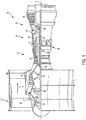
- FIG. 1 schematically illustrates a gas turbine engine 20.
- the gas turbine engine 20 is disclosed herein as a two-spool turbofan that generally incorporates a fan section 22, a compressor section 24, a combustor section 26 and a turbine section 28.
- Alternative engines might include other systems or features.
- the fan section 22 drives air along a bypass flow path B in a bypass duct, while the compressor section 24 drives air along a core flow path C for compression and communication into the combustor section 26 then expansion through the turbine section 28.
- FIG. 1 schematically illustrates a gas turbine engine 20.
- the gas turbine engine 20 is disclosed herein as a two-spool turbofan that generally incorporates a fan section 22, a compressor section 24, a combustor section 26 and a turbine section 28.
- Alternative engines might include other systems or features.
- the fan section 22 drives air along a bypass flow path B in a bypass duct
- the compressor section 24 drives air along a core flow path C for compression and communication into the combustor section 26
- the exemplary engine 20 generally includes a low speed spool 30 and a high speed spool 32 mounted for rotation about an engine central longitudinal axis A relative to an engine static structure 36 via several bearing systems 38. It should be understood that various bearing systems 38 at various locations may alternatively or additionally be provided, and the location of bearing systems 38 may be varied as appropriate to the application.
- the low speed spool 30 generally includes an inner shaft 40 that interconnects a fan 42, a low pressure compressor 44 and a low pressure turbine 46.
- the inner shaft 40 is connected to the fan 42 through a speed change mechanism, which in exemplary gas turbine engine 20 is illustrated as a geared architecture 48 to drive the fan 42 at a lower speed than the low speed spool 30.
- the high speed spool 32 includes an outer shaft 50 that interconnects a high pressure compressor 52 and high pressure turbine 54.
- a combustor 56 is arranged in exemplary gas turbine 20 between the high pressure compressor 52 and the high pressure turbine 54.
- An engine static structure 36 is arranged generally between the high pressure turbine 54 and the low pressure turbine 46.
- the engine static structure 36 further supports bearing systems 38 in the turbine section 28.
- the inner shaft 40 and the outer shaft 50 are concentric and rotate via bearing systems 38 about the engine central longitudinal axis A which is collinear with their longitudinal axes.
- each of the positions of the fan section 22, compressor section 24, combustor section 26, turbine section 28, and fan drive gear system 48 may be varied.
- gear system 48 may be located aft of combustor section 26 or even aft of turbine section 28, and fan section 22 may be positioned forward or aft of the location of gear system 48.
- the engine 20 in one example is a high-bypass geared aircraft engine.
- the engine 20 bypass ratio is greater than about six (6), with an example embodiment being greater than about ten (10)
- the geared architecture 48 is an epicyclic gear train, such as a planetary gear system or other gear system, with a gear reduction ratio of greater than about 2.3 and the low pressure turbine 46 has a pressure ratio that is greater than about five.
- the engine 20 bypass ratio is greater than about ten (10:1)
- the fan diameter is significantly larger than that of the low pressure compressor 44
- the low pressure turbine 46 has a pressure ratio that is greater than about five (5:1).
- Low pressure turbine 46 pressure ratio is pressure measured prior to inlet of low pressure turbine 46 as related to the pressure at the outlet of the low pressure turbine 46 prior to an exhaust nozzle.
- the geared architecture 48 may be an epicyclic gear train, such as a planetary gear system or other gear system, with a gear reduction ratio of greater than about 2.3:1. It should be understood, however, that the above parameters are only exemplary of one embodiment of a geared architecture engine and that the present disclosure is applicable to other gas turbine engines including direct drive turbofans.
- the fan section 22 of the engine 20 is designed for a particular flight condition--typically cruise at about 0.8 Mach and about 35,000 feet (10,668 meters).
- 'TSFC' Thrust Specific Fuel Consumption
- Low fan pressure ratio is the pressure ratio across the fan blade alone, without a Fan Exit Guide Vane (“FEGV”) system.
- the low fan pressure ratio as disclosed herein according to one non-limiting embodiment is less than about 1.45.
- Low corrected fan tip speed is the actual fan tip speed in ft/sec divided by an industry standard temperature correction of [(Tram °R)/(518.7 °R)] 0.5 .
- the "Low corrected fan tip speed” as disclosed herein according to one non-limiting embodiment is less than about 1150 ft/second (350.5 m/sec).
- cooling efficiency of hot engine components can be important for reasons such as product life and reliability.
- contaminants in cooling fluid e.g., cooling air
- can accumulate on the surface being cooled which can result in a loss of cooling efficiency.
- the problem can become worse for hot engine components that experience temperatures of at least 2200°F (1200°C) during operation, at which contaminants such as silicates of metals such as calcium, magnesium, aluminum, or any combination thereof (also known as calcium-magnesium-aluminum-silicate (“CMAS”)), or different sand, dust, and ash particulates of varying compositions can melt and fuse to the cooling surface.
- CMAS calcium-magnesium-aluminum-silicate
- Surface contour features designed to promote turbulent coolant flow or to increase cooling surface area can further exacerbate the problem of melting contaminants by contributing to wicking of any molten contaminants to spread them across the surface.
- a cooling surface on an engine component is provided with a first surface contour feature configured to increase a contact angle of a liquid on the surface.
- Such surface contour features are typically small, and can be significantly smaller than surface contour features typically included on engine component cooling surfaces for greater surface area or turbulent coolant flow.
- FIGS. 2A and 2B An example embodiment of the impact of surface contour features on liquid contact angle is schematically shown in FIGS. 2A and 2B.
- FIG. 2A shows a contact angle ⁇ 1 of a liquid 57 on a smooth surface 58
- FIG. 2B shows a contact angle ⁇ 2 of the liquid 57 on a contoured surface 59.
- a textured surface can increase the surface angle from ⁇ 1 to ⁇ 2 , and if conditions for the Cassie-Baxter model: cos ⁇ ⁇ ⁇ ⁇ 1 / r ⁇ ⁇ are satisfied (in which ⁇ is area fraction of the solid that touches the liquid and r is a solid roughness ratio for which a smooth surface equals 1), then the liquid can be suspended on the tops of surface contour roughness projections as shown in FIG. 2B , also known as "Cassie's regime".
- the first surface contour feature can include projections normal to the surface at the location of the projection.
- the first surface feature or projection can have a characteristic dimension.
- the characteristic dimension can be a height of a projection from the surface, or a width of a projection from the surface, or a spacing between adjacent projections.
- a characteristic dimension for anti-wetting surface contour features can be in a range with a lower end of 0.00001 inches (0.25 ⁇ m), 0.00004 inches (1.0 ⁇ m), or 0.0002 inches (5.1 ⁇ m), and an upper end of 0.0001 inches (2.5 ⁇ m), 0.001 inches (25 ⁇ m), or 0.01 inches (0.25 mm).
- the specified characteristic dimension or range of dimensions can be individually applied to any of a height of the surface contour features, or a width of the surface contour features, or a spacing between adjacent surface contour features. In some embodiments, the specified characteristic dimension or range of dimensions can be applied to a height of the surface contour features and to a width of the surface contour features. In some embodiments, the specified characteristic dimension or range of dimensions can be applied to a width of the surface contour features and to a spacing between adjacent surface contour features. In some embodiments, the specified characteristic dimension or range of dimensions can be applied to a height of the surface contour features and to a spacing between adjacent surface contour features. In some embodiments, the specified characteristic dimension or range of dimensions can be applied to a height of the surface contour features and to a width of the surface contour features and to a spacing between adjacent surface contour features.
- the surface contour feature can be characterized by a surface roughness parameter, such as Ra.
- Ra and other surface roughness parameters such as R ⁇ a, or ⁇ i are defined at ASME B46.1 2009, and can be measured by commercially-available surface profile measuring devices.
- the first surface contour feature can include Ra surface roughness value in a range with a lower end of 0.00005 inches (1.3 ⁇ m), 0.0002 inches (5.1 ⁇ m), or 0.001 inches (25 ⁇ m), and an upper end of 0.0004 inches (10 ⁇ m), 0.002 inches (51 ⁇ m), 0.01 inches (0.25 mm), or 0.02 inches (0.51 mm).
- the contour feature can include R ⁇ a value in a range with a lower end of 0.00001 inches (0.25 ⁇ m), 0.00004 inches (1.0 ⁇ m), or 0.0002 inches (5.1 ⁇ m), and an upper end of 0.0002 inches (5.1 ⁇ m), 0.001 inches (25 ⁇ m), or 0.005 inches (0.13 mm).
- the above range endpoints can be independently combined to make a number of different ranges, and each possible combination is hereby expressly disclosed.
- the contour feature can include ⁇ i value in a range with a lower end of 0.00002 inches (0.51 ⁇ m), 0.0001 inches (2.5 ⁇ m), or 0.0005 inches (13 ⁇ m), and an upper end of 0.0004 inches (10 ⁇ m), 0.002 inches (51 ⁇ m), or 0.01 inches (0.25 mm).
- the above range endpoints can be independently combined to make a number of different ranges, and each possible combination is hereby expressly disclosed.
- the surface hierarchical surface roughness with nanoscale and microscale structural or roughness features are examples of the surface hierarchical surface roughness with nanoscale and microscale structural or roughness features.
- a hierarchical surface contour can include a microscale roughness with Ra surface roughness values ranging from approximately 5 microns to approximately 100 microns and nanoscale roughness with Ra values ranging from approximately 250 nanometers to approximately 750 nanometers.
- the first surface contour features can take various forms, including but not limited to conical shapes, truncated spheroids (e.g., truncated prolate spheroids, truncated oblate spheroids), or truncated spheres (e.g., hemispherical or other truncated spherical projections, or projections that terminate in a hemispherical or other truncated sphere). Additionally, although this disclosure is not bound by any particular theory of operation, it is believed that the first surface contour feature can provide a plurality of points of contact with a liquid droplet, each with a high contact angle so that surface energies for wetting are inhibited.
- truncated spheroids e.g., truncated prolate spheroids, truncated oblate spheroids
- truncated spheres e.g., hemispherical or other
- the amount of surface area in actual contact with contaminant particles or droplets is low so that adhesion of the contaminant(s) to the surface is inhibited, and a reduction in contact angle results in a reduction in amount of surface of a volume of liquid that is in contact with the surface, and greater surface area of the liquid in contact with the surrounding atmosphere. This can allow for reduced friction with the surface and greater lateral force from air flow, which can promote removal of liquid droplets from the surface.
- the surface is configured to increase contact angle and reduce surface contact area in a Wenzel regime.
- the surface is configured to suspend liquid on the tops of individual surface contour projections in a Cassie regime.
- the surface contour features can also provide other technical benefits, such as providing increased surface area for heat transfer.
- the contaminant(s) will be more likely located at the bottom of gaps between macro surface contour features as described in greater detail below, leaving distal portions of the surface contour features to provide surface for heat transfer.
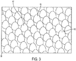
- FIG. 3 is a schematic depiction of an engine component surface 60 with truncated prolate spheroid surface contour features 62 projecting therefrom.
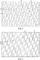
- FIG. 4 is a schematic depiction of an engine component surface 60 with conical surface contour features 64 projecting therefrom.
- FIG. 5 is a schematic depiction of an engine component surface 60 with hemisphere-terminated surface contour features 66 projecting therefrom.
- the surface projections can be discrete as shown in FIGS.
- the surface projections can instead form a continuous upper surface interspersed with discrete recesses (e.g., a grid structure with transverse grid lines forming a continuous upper surface interspersed with discrete recesses between the grid lines).
- Surface contour features configured or arranged to inhibit wetting such as the surface contour features described above can be fabricated in various ways.
- surface contour features can be fabricated using micro-lamination investment casting techniques such as described in US patent application Publication No. 2004/0156478 A1 .
- surface contour features can be fabricated using 3D printing techniques or other additive manufacturing techniques such as selective laser sintering, direct laser sintering, electron beam melting, selective laser melting, using powder or other metal build material as required by the technique.
- Subtractive manufacturing techniques such as masking and etching including reactive or energetic etching techniques such as chemical etching, plasma etching, or laser or electron beam etching.
- the engine component surface 60 can include a second surface feature.
- a second surface contour feature can be included, for example, to provide increased surface area for heat transfer or to promote turbulent coolant flow, thereby promoting effective heat transfer.
- Such surface contour features can be macro features, i.e., larger surface contour features that can provide a hierarchical surface contour in combination with the first surface contour feature.
- the surface contour features can include projections normal to the surface at the location of the projection. In some embodiments, the surface projections can be discrete projections as shown in FIGS.
- the surface projections can instead form a continuous upper surface interspersed with discrete recesses (e.g., a grid structure with transverse grid lines forming a continuous upper surface interspersed with discrete recesses between the grid lines).
- the second surface feature or projection can have a characteristic dimension.
- the characteristic dimension can be a height of a projection from the surface, or a width of a projection from the surface, or a spacing between adjacent projections.
- a characteristic dimension for the second surface contour features can be in a range with a lower end of 0.001 inches (25 ⁇ m), 0.004 inches (0.10 mm), or 0.02 inches (0.51 mm), and an upper end of 0.01 inches (0.25 mm), 0.05 inches (1.3 mm), or 0.25 inch (6.4 mm).
- the above range endpoints can be independently combined to make a number of different ranges, and each possible combination is hereby expressly disclosed.
- the specified characteristic dimension or range of dimensions can be individually applied to any of a height of the surface contour features, or a width of the surface contour features, or a spacing between adjacent surface contour features. In some embodiments, the specified characteristic dimension or range of dimensions can be applied to a height of the surface contour features and to a width of the surface contour features. In some embodiments, the specified characteristic dimension or range of dimensions can be applied to a width of the surface contour features and to a spacing between adjacent surface contour features. In some embodiments, the specified characteristic dimension or range of dimensions can be applied to a height of the surface contour features and to a spacing between adjacent surface contour features.
- the specified characteristic dimension or range of dimensions can be applied to a height of the surface contour features and to a width of the surface contour features and to a spacing between adjacent surface contour features.
- An example embodiment of a portion of a surface 60 of an engine component is shown in FIG. 6 with hemispherical first surface contour features 68, and conical second surface contour features 70.
- FIG. 7 An example embodiment of a portion of an engine component is schematically shown in FIG. 7 .
- the engine component has a first surface 72 that is in fluid and thermal communication with hot combustion gas on a hot combustion gas flow path 74, and a second surface 60 that is in fluid and thermal communication with a cooling fluid on a cooling fluid flow path 76.
- the second surface 60 includes first surface contour features 68 and second surface contour features 70.
- Liquid droplets 78 are shown in a beaded configuration (not wetted on the surface) supported on the first surface contour features 68.
Landscapes
- Engineering & Computer Science (AREA)
- Mechanical Engineering (AREA)
- General Engineering & Computer Science (AREA)
- Chemical & Material Sciences (AREA)
- Combustion & Propulsion (AREA)
- Physics & Mathematics (AREA)
- Fluid Mechanics (AREA)
- Turbine Rotor Nozzle Sealing (AREA)
Applications Claiming Priority (1)
| Application Number | Priority Date | Filing Date | Title |
|---|---|---|---|
| US16/022,658 US11739691B2 (en) | 2018-06-28 | 2018-06-28 | Engine component |
Publications (2)
| Publication Number | Publication Date |
|---|---|
| EP3587735A1 true EP3587735A1 (de) | 2020-01-01 |
| EP3587735B1 EP3587735B1 (de) | 2024-02-28 |
Family
ID=67137733
Family Applications (1)
| Application Number | Title | Priority Date | Filing Date |
|---|---|---|---|
| EP19183424.1A Active EP3587735B1 (de) | 2018-06-28 | 2019-06-28 | Bauteil eines verbrennungstriebwerks und gasturbinentriebwerk |
Country Status (2)
| Country | Link |
|---|---|
| US (1) | US11739691B2 (de) |
| EP (1) | EP3587735B1 (de) |
Families Citing this family (2)
| Publication number | Priority date | Publication date | Assignee | Title |
|---|---|---|---|---|
| US10907480B2 (en) * | 2018-09-28 | 2021-02-02 | Raytheon Technologies Corporation | Ribbed pin fins |
| JP7614980B2 (ja) * | 2021-08-25 | 2025-01-16 | 三菱重工航空エンジン株式会社 | 燃焼器パネル、及びガスタービン用燃焼器 |
Citations (9)
| Publication number | Priority date | Publication date | Assignee | Title |
|---|---|---|---|---|
| EP0926261A2 (de) * | 1997-12-23 | 1999-06-30 | United Technologies Corporation | Beschichtungen für Teile eines Gasturbinenverdichters |
| EP1186749A1 (de) * | 2000-09-07 | 2002-03-13 | Siemens Aktiengesellschaft | Strömungsmaschine sowie Turbinenschaufel |
| US20040156478A1 (en) | 2001-06-05 | 2004-08-12 | Appleby Michael P | Methods for manufacturing three-dimensional devices and devices created thereby |
| EP1935509A1 (de) * | 2006-12-19 | 2008-06-25 | General Electric Company | Gegenstände mit Antifouling-Oberflächen und deren Herstellungsverfahren |
| DE102009003898A1 (de) * | 2009-01-03 | 2010-07-08 | Harald Prof. Dr. Dr. habil. Reiss | Turbinenschaufeln und andere massive Bauteile |
| WO2011089025A2 (en) * | 2010-01-20 | 2011-07-28 | Gardner Denver Deutschland Gmbh | Expansion turbine for the expansion of gas |
| WO2013019257A1 (en) * | 2011-08-03 | 2013-02-07 | Massachusetts Institute Of Technology | Articles for manipulating impinging liquids and methods of manufacturing same |
| WO2013133997A1 (en) * | 2012-03-09 | 2013-09-12 | United Technologies Corporation | Erosion resistant and hydrophobic article |
| US20150198380A1 (en) * | 2012-07-18 | 2015-07-16 | University Of Virginia Patent Foundation | Heat transfer device for high heat flux applications and related methods thereof |
Family Cites Families (8)
| Publication number | Priority date | Publication date | Assignee | Title |
|---|---|---|---|---|
| US6468669B1 (en) * | 1999-05-03 | 2002-10-22 | General Electric Company | Article having turbulation and method of providing turbulation on an article |
| US6402464B1 (en) * | 2000-08-29 | 2002-06-11 | General Electric Company | Enhanced heat transfer surface for cast-in-bump-covered cooling surfaces and methods of enhancing heat transfer |
| US7919151B2 (en) | 2006-12-14 | 2011-04-05 | General Electric Company | Methods of preparing wetting-resistant surfaces and articles incorporating the same |
| US20090183850A1 (en) * | 2008-01-23 | 2009-07-23 | Siemens Power Generation, Inc. | Method of Making a Combustion Turbine Component from Metallic Combustion Turbine Subcomponent Greenbodies |
| US8894367B2 (en) * | 2009-08-06 | 2014-11-25 | Siemens Energy, Inc. | Compound cooling flow turbulator for turbine component |
| US9243502B2 (en) * | 2012-04-24 | 2016-01-26 | United Technologies Corporation | Airfoil cooling enhancement and method of making the same |
| US20170159487A1 (en) * | 2015-12-02 | 2017-06-08 | General Electric Company | HT Enhancement Bumps/Features on Cold Side |
| US20170191417A1 (en) | 2016-01-06 | 2017-07-06 | General Electric Company | Engine component assembly |
-
2018
- 2018-06-28 US US16/022,658 patent/US11739691B2/en active Active
-
2019
- 2019-06-28 EP EP19183424.1A patent/EP3587735B1/de active Active
Patent Citations (9)
| Publication number | Priority date | Publication date | Assignee | Title |
|---|---|---|---|---|
| EP0926261A2 (de) * | 1997-12-23 | 1999-06-30 | United Technologies Corporation | Beschichtungen für Teile eines Gasturbinenverdichters |
| EP1186749A1 (de) * | 2000-09-07 | 2002-03-13 | Siemens Aktiengesellschaft | Strömungsmaschine sowie Turbinenschaufel |
| US20040156478A1 (en) | 2001-06-05 | 2004-08-12 | Appleby Michael P | Methods for manufacturing three-dimensional devices and devices created thereby |
| EP1935509A1 (de) * | 2006-12-19 | 2008-06-25 | General Electric Company | Gegenstände mit Antifouling-Oberflächen und deren Herstellungsverfahren |
| DE102009003898A1 (de) * | 2009-01-03 | 2010-07-08 | Harald Prof. Dr. Dr. habil. Reiss | Turbinenschaufeln und andere massive Bauteile |
| WO2011089025A2 (en) * | 2010-01-20 | 2011-07-28 | Gardner Denver Deutschland Gmbh | Expansion turbine for the expansion of gas |
| WO2013019257A1 (en) * | 2011-08-03 | 2013-02-07 | Massachusetts Institute Of Technology | Articles for manipulating impinging liquids and methods of manufacturing same |
| WO2013133997A1 (en) * | 2012-03-09 | 2013-09-12 | United Technologies Corporation | Erosion resistant and hydrophobic article |
| US20150198380A1 (en) * | 2012-07-18 | 2015-07-16 | University Of Virginia Patent Foundation | Heat transfer device for high heat flux applications and related methods thereof |
Also Published As
| Publication number | Publication date |
|---|---|
| US20200003120A1 (en) | 2020-01-02 |
| US11739691B2 (en) | 2023-08-29 |
| EP3587735B1 (de) | 2024-02-28 |
Similar Documents
| Publication | Publication Date | Title |
|---|---|---|
| EP3748126B1 (de) | Komponenten für gasturbinentriebwerke | |
| EP3070406A1 (de) | Motorbauteil | |
| US20200347734A1 (en) | Cooling schemes for airfoils for gas turbine engines | |
| EP3406852B1 (de) | Turbinenbauteil mit spitzenfilmkühlung und verfahren zur kühlung | |
| EP3034791A1 (de) | Wärmeübertragungssockel mit strömungsführungsmerkmalen | |
| CN112523820A (zh) | 涡轮发动机组件 | |
| EP3587735B1 (de) | Bauteil eines verbrennungstriebwerks und gasturbinentriebwerk | |
| EP3219920A1 (de) | Komponente für einen turbinenmotor mit einem filmloch | |
| EP3508695B1 (de) | Laufschaufel eines gasturbinentriebwerks mit kühlräumen | |
| EP3444435B1 (de) | Expansionsdichtun für schaufelblatt eines gasturbinentriebwerks | |
| EP3502420B1 (de) | Bauteil für ein gasturbinentriebwerk und zugehöriges gasturbinentriebwerk | |
| EP3470629B1 (de) | Anordnung von filmkühlungsbohrungen für turbotriebwerkskomponenten | |
| EP3736087A1 (de) | Systeme und verfahren zur herstellung von komponenten für einen gasturbinenmotor | |
| EP3287598B1 (de) | Kühlungsmerkmale mit dreidimensionaler fischgrat-geometrie | |
| EP3467269B1 (de) | Stolperstreifen und filmkühlungsloch für turbostrahltriebwerkskomponenten | |
| EP3663517B1 (de) | Bauteil für ein gasturbinentriebwerk und zugehöriges gasturbinentriebwerk | |
| EP3564486B1 (de) | Schaufel mit verbessertem kühlschema | |
| EP3495618B1 (de) | Schaufelblatt mit internen kühlkanälen | |
| US10443406B2 (en) | Airfoil having non-leading edge stagnation line cooling scheme | |
| EP4417790A1 (de) | Schaufelprofil mit versetzter kühllochkonfiguration | |
| EP3926142A1 (de) | Lüfterschaufel mit integraler dosiervorrichtung zur steuerung des gasdrucks innerhalb einer lüfterschaufel | |
| EP3495619A1 (de) | Schaufelblatt mit internen kühlkanälen |
Legal Events
| Date | Code | Title | Description |
|---|---|---|---|
| PUAI | Public reference made under article 153(3) epc to a published international application that has entered the european phase |
Free format text: ORIGINAL CODE: 0009012 |
|
| STAA | Information on the status of an ep patent application or granted ep patent |
Free format text: STATUS: THE APPLICATION HAS BEEN PUBLISHED |
|
| AK | Designated contracting states |
Kind code of ref document: A1 Designated state(s): AL AT BE BG CH CY CZ DE DK EE ES FI FR GB GR HR HU IE IS IT LI LT LU LV MC MK MT NL NO PL PT RO RS SE SI SK SM TR |
|
| STAA | Information on the status of an ep patent application or granted ep patent |
Free format text: STATUS: REQUEST FOR EXAMINATION WAS MADE |
|
| 17P | Request for examination filed |
Effective date: 20200701 |
|
| RBV | Designated contracting states (corrected) |
Designated state(s): AL AT BE BG CH CY CZ DE DK EE ES FI FR GB GR HR HU IE IS IT LI LT LU LV MC MK MT NL NO PL PT RO RS SE SI SK SM TR |
|
| RAP1 | Party data changed (applicant data changed or rights of an application transferred) |
Owner name: RAYTHEON TECHNOLOGIES CORPORATION |
|
| STAA | Information on the status of an ep patent application or granted ep patent |
Free format text: STATUS: EXAMINATION IS IN PROGRESS |
|
| 17Q | First examination report despatched |
Effective date: 20210520 |
|
| GRAP | Despatch of communication of intention to grant a patent |
Free format text: ORIGINAL CODE: EPIDOSNIGR1 |
|
| STAA | Information on the status of an ep patent application or granted ep patent |
Free format text: STATUS: GRANT OF PATENT IS INTENDED |
|
| RIC1 | Information provided on ipc code assigned before grant |
Ipc: B08B 17/06 20060101ALN20230209BHEP Ipc: F23R 3/00 20060101ALN20230209BHEP Ipc: F02C 7/18 20060101ALI20230209BHEP Ipc: F01D 25/12 20060101ALI20230209BHEP Ipc: F01D 25/00 20060101ALI20230209BHEP Ipc: F01D 9/06 20060101ALI20230209BHEP Ipc: F01D 5/18 20060101AFI20230209BHEP |
|
| INTG | Intention to grant announced |
Effective date: 20230309 |
|
| GRAJ | Information related to disapproval of communication of intention to grant by the applicant or resumption of examination proceedings by the epo deleted |
Free format text: ORIGINAL CODE: EPIDOSDIGR1 |
|
| STAA | Information on the status of an ep patent application or granted ep patent |
Free format text: STATUS: EXAMINATION IS IN PROGRESS |
|
| INTC | Intention to grant announced (deleted) | ||
| GRAP | Despatch of communication of intention to grant a patent |
Free format text: ORIGINAL CODE: EPIDOSNIGR1 |
|
| STAA | Information on the status of an ep patent application or granted ep patent |
Free format text: STATUS: GRANT OF PATENT IS INTENDED |
|
| RIC1 | Information provided on ipc code assigned before grant |
Ipc: B08B 17/06 20060101ALN20230905BHEP Ipc: F23R 3/00 20060101ALN20230905BHEP Ipc: F02C 7/18 20060101ALI20230905BHEP Ipc: F01D 25/12 20060101ALI20230905BHEP Ipc: F01D 25/00 20060101ALI20230905BHEP Ipc: F01D 9/06 20060101ALI20230905BHEP Ipc: F01D 5/18 20060101AFI20230905BHEP |
|
| INTG | Intention to grant announced |
Effective date: 20230919 |
|
| RAP3 | Party data changed (applicant data changed or rights of an application transferred) |
Owner name: RTX CORPORATION |
|
| GRAS | Grant fee paid |
Free format text: ORIGINAL CODE: EPIDOSNIGR3 |
|
| GRAA | (expected) grant |
Free format text: ORIGINAL CODE: 0009210 |
|
| STAA | Information on the status of an ep patent application or granted ep patent |
Free format text: STATUS: THE PATENT HAS BEEN GRANTED |
|
| AK | Designated contracting states |
Kind code of ref document: B1 Designated state(s): AL AT BE BG CH CY CZ DE DK EE ES FI FR GB GR HR HU IE IS IT LI LT LU LV MC MK MT NL NO PL PT RO RS SE SI SK SM TR |
|
| REG | Reference to a national code |
Ref country code: GB Ref legal event code: FG4D |
|
| REG | Reference to a national code |
Ref country code: CH Ref legal event code: EP |
|
| REG | Reference to a national code |
Ref country code: DE Ref legal event code: R096 Ref document number: 602019047197 Country of ref document: DE |
|
| REG | Reference to a national code |
Ref country code: IE Ref legal event code: FG4D |
|
| REG | Reference to a national code |
Ref country code: LT Ref legal event code: MG9D |
|
| PG25 | Lapsed in a contracting state [announced via postgrant information from national office to epo] |
Ref country code: IS Free format text: LAPSE BECAUSE OF FAILURE TO SUBMIT A TRANSLATION OF THE DESCRIPTION OR TO PAY THE FEE WITHIN THE PRESCRIBED TIME-LIMIT Effective date: 20240628 |
|
| REG | Reference to a national code |
Ref country code: NL Ref legal event code: MP Effective date: 20240228 |
|
| PG25 | Lapsed in a contracting state [announced via postgrant information from national office to epo] |
Ref country code: LT Free format text: LAPSE BECAUSE OF FAILURE TO SUBMIT A TRANSLATION OF THE DESCRIPTION OR TO PAY THE FEE WITHIN THE PRESCRIBED TIME-LIMIT Effective date: 20240228 |
|
| PG25 | Lapsed in a contracting state [announced via postgrant information from national office to epo] |
Ref country code: GR Free format text: LAPSE BECAUSE OF FAILURE TO SUBMIT A TRANSLATION OF THE DESCRIPTION OR TO PAY THE FEE WITHIN THE PRESCRIBED TIME-LIMIT Effective date: 20240529 |
|
| PG25 | Lapsed in a contracting state [announced via postgrant information from national office to epo] |
Ref country code: NL Free format text: LAPSE BECAUSE OF FAILURE TO SUBMIT A TRANSLATION OF THE DESCRIPTION OR TO PAY THE FEE WITHIN THE PRESCRIBED TIME-LIMIT Effective date: 20240228 Ref country code: HR Free format text: LAPSE BECAUSE OF FAILURE TO SUBMIT A TRANSLATION OF THE DESCRIPTION OR TO PAY THE FEE WITHIN THE PRESCRIBED TIME-LIMIT Effective date: 20240228 Ref country code: RS Free format text: LAPSE BECAUSE OF FAILURE TO SUBMIT A TRANSLATION OF THE DESCRIPTION OR TO PAY THE FEE WITHIN THE PRESCRIBED TIME-LIMIT Effective date: 20240528 |
|
| PG25 | Lapsed in a contracting state [announced via postgrant information from national office to epo] |
Ref country code: ES Free format text: LAPSE BECAUSE OF FAILURE TO SUBMIT A TRANSLATION OF THE DESCRIPTION OR TO PAY THE FEE WITHIN THE PRESCRIBED TIME-LIMIT Effective date: 20240228 |
|
| PG25 | Lapsed in a contracting state [announced via postgrant information from national office to epo] |
Ref country code: RS Free format text: LAPSE BECAUSE OF FAILURE TO SUBMIT A TRANSLATION OF THE DESCRIPTION OR TO PAY THE FEE WITHIN THE PRESCRIBED TIME-LIMIT Effective date: 20240528 Ref country code: NO Free format text: LAPSE BECAUSE OF FAILURE TO SUBMIT A TRANSLATION OF THE DESCRIPTION OR TO PAY THE FEE WITHIN THE PRESCRIBED TIME-LIMIT Effective date: 20240528 Ref country code: NL Free format text: LAPSE BECAUSE OF FAILURE TO SUBMIT A TRANSLATION OF THE DESCRIPTION OR TO PAY THE FEE WITHIN THE PRESCRIBED TIME-LIMIT Effective date: 20240228 Ref country code: LT Free format text: LAPSE BECAUSE OF FAILURE TO SUBMIT A TRANSLATION OF THE DESCRIPTION OR TO PAY THE FEE WITHIN THE PRESCRIBED TIME-LIMIT Effective date: 20240228 Ref country code: IS Free format text: LAPSE BECAUSE OF FAILURE TO SUBMIT A TRANSLATION OF THE DESCRIPTION OR TO PAY THE FEE WITHIN THE PRESCRIBED TIME-LIMIT Effective date: 20240628 Ref country code: HR Free format text: LAPSE BECAUSE OF FAILURE TO SUBMIT A TRANSLATION OF THE DESCRIPTION OR TO PAY THE FEE WITHIN THE PRESCRIBED TIME-LIMIT Effective date: 20240228 Ref country code: GR Free format text: LAPSE BECAUSE OF FAILURE TO SUBMIT A TRANSLATION OF THE DESCRIPTION OR TO PAY THE FEE WITHIN THE PRESCRIBED TIME-LIMIT Effective date: 20240529 Ref country code: FI Free format text: LAPSE BECAUSE OF FAILURE TO SUBMIT A TRANSLATION OF THE DESCRIPTION OR TO PAY THE FEE WITHIN THE PRESCRIBED TIME-LIMIT Effective date: 20240228 Ref country code: ES Free format text: LAPSE BECAUSE OF FAILURE TO SUBMIT A TRANSLATION OF THE DESCRIPTION OR TO PAY THE FEE WITHIN THE PRESCRIBED TIME-LIMIT Effective date: 20240228 Ref country code: BG Free format text: LAPSE BECAUSE OF FAILURE TO SUBMIT A TRANSLATION OF THE DESCRIPTION OR TO PAY THE FEE WITHIN THE PRESCRIBED TIME-LIMIT Effective date: 20240228 |
|
| PG25 | Lapsed in a contracting state [announced via postgrant information from national office to epo] |
Ref country code: PL Free format text: LAPSE BECAUSE OF FAILURE TO SUBMIT A TRANSLATION OF THE DESCRIPTION OR TO PAY THE FEE WITHIN THE PRESCRIBED TIME-LIMIT Effective date: 20240228 Ref country code: PT Free format text: LAPSE BECAUSE OF FAILURE TO SUBMIT A TRANSLATION OF THE DESCRIPTION OR TO PAY THE FEE WITHIN THE PRESCRIBED TIME-LIMIT Effective date: 20240628 |
|
| REG | Reference to a national code |
Ref country code: AT Ref legal event code: MK05 Ref document number: 1661414 Country of ref document: AT Kind code of ref document: T Effective date: 20240228 |
|
| PG25 | Lapsed in a contracting state [announced via postgrant information from national office to epo] |
Ref country code: SE Free format text: LAPSE BECAUSE OF FAILURE TO SUBMIT A TRANSLATION OF THE DESCRIPTION OR TO PAY THE FEE WITHIN THE PRESCRIBED TIME-LIMIT Effective date: 20240228 Ref country code: PT Free format text: LAPSE BECAUSE OF FAILURE TO SUBMIT A TRANSLATION OF THE DESCRIPTION OR TO PAY THE FEE WITHIN THE PRESCRIBED TIME-LIMIT Effective date: 20240628 Ref country code: PL Free format text: LAPSE BECAUSE OF FAILURE TO SUBMIT A TRANSLATION OF THE DESCRIPTION OR TO PAY THE FEE WITHIN THE PRESCRIBED TIME-LIMIT Effective date: 20240228 Ref country code: LV Free format text: LAPSE BECAUSE OF FAILURE TO SUBMIT A TRANSLATION OF THE DESCRIPTION OR TO PAY THE FEE WITHIN THE PRESCRIBED TIME-LIMIT Effective date: 20240228 |
|
| PG25 | Lapsed in a contracting state [announced via postgrant information from national office to epo] |
Ref country code: DK Free format text: LAPSE BECAUSE OF FAILURE TO SUBMIT A TRANSLATION OF THE DESCRIPTION OR TO PAY THE FEE WITHIN THE PRESCRIBED TIME-LIMIT Effective date: 20240228 |
|
| PG25 | Lapsed in a contracting state [announced via postgrant information from national office to epo] |
Ref country code: SM Free format text: LAPSE BECAUSE OF FAILURE TO SUBMIT A TRANSLATION OF THE DESCRIPTION OR TO PAY THE FEE WITHIN THE PRESCRIBED TIME-LIMIT Effective date: 20240228 |
|
| PG25 | Lapsed in a contracting state [announced via postgrant information from national office to epo] |
Ref country code: CZ Free format text: LAPSE BECAUSE OF FAILURE TO SUBMIT A TRANSLATION OF THE DESCRIPTION OR TO PAY THE FEE WITHIN THE PRESCRIBED TIME-LIMIT Effective date: 20240228 Ref country code: EE Free format text: LAPSE BECAUSE OF FAILURE TO SUBMIT A TRANSLATION OF THE DESCRIPTION OR TO PAY THE FEE WITHIN THE PRESCRIBED TIME-LIMIT Effective date: 20240228 |
|
| PG25 | Lapsed in a contracting state [announced via postgrant information from national office to epo] |
Ref country code: AT Free format text: LAPSE BECAUSE OF FAILURE TO SUBMIT A TRANSLATION OF THE DESCRIPTION OR TO PAY THE FEE WITHIN THE PRESCRIBED TIME-LIMIT Effective date: 20240228 |
|
| PG25 | Lapsed in a contracting state [announced via postgrant information from national office to epo] |
Ref country code: SK Free format text: LAPSE BECAUSE OF FAILURE TO SUBMIT A TRANSLATION OF THE DESCRIPTION OR TO PAY THE FEE WITHIN THE PRESCRIBED TIME-LIMIT Effective date: 20240228 |
|
| PG25 | Lapsed in a contracting state [announced via postgrant information from national office to epo] |
Ref country code: SM Free format text: LAPSE BECAUSE OF FAILURE TO SUBMIT A TRANSLATION OF THE DESCRIPTION OR TO PAY THE FEE WITHIN THE PRESCRIBED TIME-LIMIT Effective date: 20240228 Ref country code: SK Free format text: LAPSE BECAUSE OF FAILURE TO SUBMIT A TRANSLATION OF THE DESCRIPTION OR TO PAY THE FEE WITHIN THE PRESCRIBED TIME-LIMIT Effective date: 20240228 Ref country code: RO Free format text: LAPSE BECAUSE OF FAILURE TO SUBMIT A TRANSLATION OF THE DESCRIPTION OR TO PAY THE FEE WITHIN THE PRESCRIBED TIME-LIMIT Effective date: 20240228 Ref country code: EE Free format text: LAPSE BECAUSE OF FAILURE TO SUBMIT A TRANSLATION OF THE DESCRIPTION OR TO PAY THE FEE WITHIN THE PRESCRIBED TIME-LIMIT Effective date: 20240228 Ref country code: DK Free format text: LAPSE BECAUSE OF FAILURE TO SUBMIT A TRANSLATION OF THE DESCRIPTION OR TO PAY THE FEE WITHIN THE PRESCRIBED TIME-LIMIT Effective date: 20240228 Ref country code: CZ Free format text: LAPSE BECAUSE OF FAILURE TO SUBMIT A TRANSLATION OF THE DESCRIPTION OR TO PAY THE FEE WITHIN THE PRESCRIBED TIME-LIMIT Effective date: 20240228 Ref country code: AT Free format text: LAPSE BECAUSE OF FAILURE TO SUBMIT A TRANSLATION OF THE DESCRIPTION OR TO PAY THE FEE WITHIN THE PRESCRIBED TIME-LIMIT Effective date: 20240228 |
|
| REG | Reference to a national code |
Ref country code: DE Ref legal event code: R097 Ref document number: 602019047197 Country of ref document: DE |
|
| PG25 | Lapsed in a contracting state [announced via postgrant information from national office to epo] |
Ref country code: IT Free format text: LAPSE BECAUSE OF FAILURE TO SUBMIT A TRANSLATION OF THE DESCRIPTION OR TO PAY THE FEE WITHIN THE PRESCRIBED TIME-LIMIT Effective date: 20240228 |
|
| PG25 | Lapsed in a contracting state [announced via postgrant information from national office to epo] |
Ref country code: IT Free format text: LAPSE BECAUSE OF FAILURE TO SUBMIT A TRANSLATION OF THE DESCRIPTION OR TO PAY THE FEE WITHIN THE PRESCRIBED TIME-LIMIT Effective date: 20240228 |
|
| PLBE | No opposition filed within time limit |
Free format text: ORIGINAL CODE: 0009261 |
|
| STAA | Information on the status of an ep patent application or granted ep patent |
Free format text: STATUS: NO OPPOSITION FILED WITHIN TIME LIMIT |
|
| PG25 | Lapsed in a contracting state [announced via postgrant information from national office to epo] |
Ref country code: MC Free format text: LAPSE BECAUSE OF FAILURE TO SUBMIT A TRANSLATION OF THE DESCRIPTION OR TO PAY THE FEE WITHIN THE PRESCRIBED TIME-LIMIT Effective date: 20240228 |
|
| REG | Reference to a national code |
Ref country code: CH Ref legal event code: PL |
|
| 26N | No opposition filed |
Effective date: 20241129 |
|
| PG25 | Lapsed in a contracting state [announced via postgrant information from national office to epo] |
Ref country code: LU Free format text: LAPSE BECAUSE OF NON-PAYMENT OF DUE FEES Effective date: 20240628 |
|
| PG25 | Lapsed in a contracting state [announced via postgrant information from national office to epo] |
Ref country code: IE Free format text: LAPSE BECAUSE OF NON-PAYMENT OF DUE FEES Effective date: 20240628 |
|
| PG25 | Lapsed in a contracting state [announced via postgrant information from national office to epo] |
Ref country code: SI Free format text: LAPSE BECAUSE OF FAILURE TO SUBMIT A TRANSLATION OF THE DESCRIPTION OR TO PAY THE FEE WITHIN THE PRESCRIBED TIME-LIMIT Effective date: 20240228 Ref country code: BE Free format text: LAPSE BECAUSE OF NON-PAYMENT OF DUE FEES Effective date: 20240630 Ref country code: CH Free format text: LAPSE BECAUSE OF NON-PAYMENT OF DUE FEES Effective date: 20240630 |
|
| REG | Reference to a national code |
Ref country code: BE Ref legal event code: MM Effective date: 20240630 |
|
| PGFP | Annual fee paid to national office [announced via postgrant information from national office to epo] |
Ref country code: DE Payment date: 20250520 Year of fee payment: 7 |
|
| PGFP | Annual fee paid to national office [announced via postgrant information from national office to epo] |
Ref country code: GB Payment date: 20250520 Year of fee payment: 7 |
|
| PGFP | Annual fee paid to national office [announced via postgrant information from national office to epo] |
Ref country code: FR Payment date: 20250520 Year of fee payment: 7 |
|
| PG25 | Lapsed in a contracting state [announced via postgrant information from national office to epo] |
Ref country code: CY Free format text: LAPSE BECAUSE OF FAILURE TO SUBMIT A TRANSLATION OF THE DESCRIPTION OR TO PAY THE FEE WITHIN THE PRESCRIBED TIME-LIMIT; INVALID AB INITIO Effective date: 20190628 |
|
| PG25 | Lapsed in a contracting state [announced via postgrant information from national office to epo] |
Ref country code: HU Free format text: LAPSE BECAUSE OF FAILURE TO SUBMIT A TRANSLATION OF THE DESCRIPTION OR TO PAY THE FEE WITHIN THE PRESCRIBED TIME-LIMIT; INVALID AB INITIO Effective date: 20190628 |