EP3599302A1 - Système anneau/curseur pour machine à filer à anneaux - Google Patents
Système anneau/curseur pour machine à filer à anneaux Download PDFInfo
- Publication number
- EP3599302A1 EP3599302A1 EP19185376.1A EP19185376A EP3599302A1 EP 3599302 A1 EP3599302 A1 EP 3599302A1 EP 19185376 A EP19185376 A EP 19185376A EP 3599302 A1 EP3599302 A1 EP 3599302A1
- Authority
- EP
- European Patent Office
- Prior art keywords
- ring
- traveler
- dimples
- dimple
- accretion
- Prior art date
- Legal status (The legal status is an assumption and is not a legal conclusion. Google has not performed a legal analysis and makes no representation as to the accuracy of the status listed.)
- Granted
Links
Images



Classifications
-
- D—TEXTILES; PAPER
- D01—NATURAL OR MAN-MADE THREADS OR FIBRES; SPINNING
- D01H—SPINNING OR TWISTING
- D01H7/00—Spinning or twisting arrangements
- D01H7/02—Spinning or twisting arrangements for imparting permanent twist
- D01H7/52—Ring-and-traveller arrangements
-
- C—CHEMISTRY; METALLURGY
- C25—ELECTROLYTIC OR ELECTROPHORETIC PROCESSES; APPARATUS THEREFOR
- C25D—PROCESSES FOR THE ELECTROLYTIC OR ELECTROPHORETIC PRODUCTION OF COATINGS; ELECTROFORMING; APPARATUS THEREFOR
- C25D5/00—Electroplating characterised by the process; Pretreatment or after-treatment of workpieces
- C25D5/02—Electroplating of selected surface areas
-
- C—CHEMISTRY; METALLURGY
- C25—ELECTROLYTIC OR ELECTROPHORETIC PROCESSES; APPARATUS THEREFOR
- C25D—PROCESSES FOR THE ELECTROLYTIC OR ELECTROPHORETIC PRODUCTION OF COATINGS; ELECTROFORMING; APPARATUS THEREFOR
- C25D7/00—Electroplating characterised by the article coated
- C25D7/04—Tubes; Rings; Hollow bodies
-
- D—TEXTILES; PAPER
- D01—NATURAL OR MAN-MADE THREADS OR FIBRES; SPINNING
- D01H—SPINNING OR TWISTING
- D01H7/00—Spinning or twisting arrangements
- D01H7/02—Spinning or twisting arrangements for imparting permanent twist
- D01H7/52—Ring-and-traveller arrangements
- D01H7/60—Rings or travellers; Manufacture thereof not otherwise provided for ; Cleaning means for rings
- D01H7/602—Rings
-
- D—TEXTILES; PAPER
- D01—NATURAL OR MAN-MADE THREADS OR FIBRES; SPINNING
- D01H—SPINNING OR TWISTING
- D01H7/00—Spinning or twisting arrangements
- D01H7/02—Spinning or twisting arrangements for imparting permanent twist
- D01H7/52—Ring-and-traveller arrangements
- D01H7/60—Rings or travellers; Manufacture thereof not otherwise provided for ; Cleaning means for rings
- D01H7/604—Travellers
Definitions
- the present invention relates to a ring/traveler system for a ring spinning machine.
- a method of employing a lubricating liquid such as oil may be used as a method for suppressing wear on the traveler and the ring. With this method, however, the lubricating liquid adheres to and soils the yarn.
- Japanese Patent Application Publication No. 2015-203175 describes an invention relating to a ring/traveler system for a ring spinning machine and states that in order to extend the useful life of the ring/traveler system without using a lubricating liquid, "in a ring/traveler system for a ring spinning machine, circular indentations, each having a depth of 0.5 to 8 ⁇ m and a diameter of 5 to 30 ⁇ m, are formed in a sliding surface, which is a surface on which a traveler and a ring slide as the traveler travels, within an area ratio range of 5% to 16%".
- the present invention has been designed to solve the problem described above, and an object thereof is to provide a ring/traveler system for a ring spinning machine in which the shape and arrangement of dimples that function to resupply an accretion containing a yarn-derived lubricating component to a sliding surface have been studied in depth, with the result that the shape and arrangement of dimples formed on a sliding surface between a traveler and a ring can be optimized, enabling a further extension to the useful life of the ring/traveler system.
- the present invention is a ring/traveler system for a ring spinning machine in which sliding is performed in an environment without liquid lubrication, wherein a plurality of dimples, each having a circular open end, are formed in a sliding surface on which a traveler and a ring slide as the traveler travels, and the plurality of dimples satisfy a condition according to which a dimple wall surface angle is not less than 10° and not more than 65° and satisfy a condition according to which a value of P/D, where P is the pitch ( ⁇ m) at which the plurality of dimples are arranged over the sliding surface and D is the diameter ( ⁇ m) of the circular open end, is not less than 1.9 and not more than 4.5.
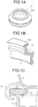
- FIG. 1A is a perspective view of a ring in an example configuration of a ring/traveler system for a ring spinning machine.
- FIG. 1B is a partially enlarged perspective view of the ring in this example configuration of a ring/traveler system for a ring spinning machine.
- FIG. 1C is a schematic perspective view showing a relationship between the traveler and the ring during spinning in this example configuration of a ring/traveler system for a ring spinning machine.
- the term "ring spinning machine” denotes a spinning machine such as a ring spinning machine or a ring twisting machine in which yarn is wound via a traveler that travels (slides) around a ring that ascends and descends while supported by a ring rail.
- a ring 11 and a traveler 12 together constitute the ring/traveler system.
- the ring 11 is formed from bearing steel, for example.
- a flange 11a is formed on the ring 11 so as to be structured integrally with the ring 11.
- the flange 11a is formed to have a T-shaped cross-section.
- the traveler 12 meanwhile, is formed from oxidation-treated spring steel, for example.
- the traveler 12 is formed in a C shape.
- the traveler 12 is mounted on the flange 11a of the ring 11.
- a chromium plating layer 13 is formed on the surface of the flange 11a of the ring 11.
- the chromium plating layer 13 is preferably formed from a hard chromium plating layer with a thickness of approximately 10 to 20 ⁇ m, for example.
- a hard chromium plating layer is a plating layer defined in JIS H8615 Chromium plating for engineering purposes.
- a periodic structure portion 14 is formed on the chromium plating layer 13 covering the flange 11a in at least a surface layer part of the chromium plating layer 13 covering an inner peripheral surface of the flange 11a.
- the periodic structure portion 14 is a part for reducing component wear that occurs when the traveler 12 slides around the ring 11.
- the flange 11a of the ring 11 is covered by the chromium plating layer 13, and the periodic structure portion 14 is formed on the inner peripheral surface of the flange 11a via the chromium plating layer 13.
- the film covering the flange 11a is not limited to the chromium plating layer 13, however, and any surface-treated film having either approximately identical mechanical characteristics to the chromium plating layer 13 or higher mechanical characteristics than the traveler material, such as nickel plating having a higher hardness than the traveler material, for example, may be used instead.
- a sliding surface on which the traveler 12 and the ring 11 slide as the traveler 12 travels is a surface on which the ring 11 and the traveler 12 contact each other. Therefore, a sliding surface between the traveler 12 and the ring 11 exists on both the ring 11 and the traveler 12.
- the periodic structure portion 14 is formed on the sliding surface on which the ring 11 slides relative to the traveler 12. More specifically, a configuration in which the inner peripheral surface of the flange 11a of the ring 11 is covered by the chromium plating layer 13 and the periodic structure portion 14 is formed on the surface of the chromium plating layer 13 is employed. In this embodiment, therefore, the periodic structure portion 14 on the chromium plating layer 13 covering the inner peripheral surface of the flange 11a corresponds to the sliding surface between the traveler 12 and the ring 11.
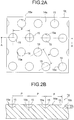
- FIGS. 2A and 2B a plurality of dimples 15 are formed in the periodic structure portion 14 of the chromium plating layer 13.
- FIG. 2A is a front view of the periodic structure portion
- FIG. 2B is an A-A sectional view of FIG. 2A .
- the periodic structure portion 14 is formed by arranging the plurality of dimples 15 periodically at a predetermined pitch.
- the plurality of dimples 15 are arranged in a staggered pattern.
- Each dimple 15 is formed as a recess in a main surface 14a of the periodic structure portion 14.
- the main surface 14a of the periodic structure portion 14 is a surface excluding the recessed parts formed by the dimples 15.
- the plurality of dimples 15 each have a circular open end 15a.
- the open end 15a of each dimple 15 opens in a circular shape onto the main surface 14a of the periodic structure portion 14.
- Each dimple 15 is formed to have a rounded cone-shaped cross-section.
- each dimple 15 has a wall surface 15b that rises diagonally from a bottom portion of the dimple 15 toward the main surface 14a of the periodic structure portion 14.
- the plurality of dimples 15 forming the periodic structure portion 14 are formed to satisfy the following two conditions simultaneously.
- the dimple wall surface angle is not less than 10° and not more than 65°
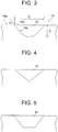
- the dimple wall surface angle is denoted by an angle ⁇ (°) formed by the main surface 14a and the wall surface 15b at the open end 15a where the wall surface 15b of the dimple 15 contacts the main surface 14a of the periodic structure portion 14.
- the dimple pitch is denoted by a center-to-center distance P ( ⁇ m) between two adjacent dimples 15 on the main surface 14a of the periodic structure portion 14. Note that FIGS. 2A and 2B show an example in which the arrangement pitch P of the dimples 15 is identical in all directions, but the arrangement pitch may be varied according to the direction of the adjacent dimples 15.
- the dimple diameter is denoted by a diameter D ( ⁇ m) of the open end 15a of the dimple 15, which opens in a circular shape onto the main surface 14a of the periodic structure portion 14.
- the dimple depth is denoted by a maximum depth S ( ⁇ m) of the dimple 15, using the main surface 14a of the periodic structure portion 14 as a reference.
- FIG. 3 shows an example in which the dimples 15 have a rounded cone-shaped cross-section, but the present invention is not limited thereto, and instead, for example, the employed dimples 15 may have a pointed cone-shaped cross-section, as shown in FIG. 4 , or a trapezoidal cross-section, as shown in FIG. 5 . Regardless of the employed sectional shape, the open end 15a of the dimple 15 is circular.
- the term "circular” used to describe the opening shape of the open end 15a preferably denotes a perfect circle.
- the present invention is not limited thereto, however, and the term “circular” may denote an ellipse having an ellipticity of at least 0.8, for example.
- the dimple wall surface angle ⁇ in this case, the dimple wall surface angle ⁇ should satisfy the condition of being not less than 10° and not more than 65° in at least one of a long axis direction and a short axis direction of the ellipse.
- the condition according to which the value of P/D is not less than 1.9 and not more than 4.5 should be satisfied when the length of at least one of a long axis and a short axis of the ellipse is applied as the dimple diameter D ( ⁇ m).
- the dimple depth S of each of the plurality of dimples 15 is preferably not less than 2 ⁇ m. Further, the dimple diameter D is preferably not less than 10 ⁇ m and not more than 60 ⁇ m. Furthermore, a dimple area ratio of the periodic structure portion 14 is preferably not less than 4% and not more than 20%. The dimple area ratio is a value expressing the ratio of the entire surface area of the dimples 15 to the entire surface area of the sliding surface between the traveler 12 and the ring 11 as a percentage.
- the plurality of dimples 15 can be formed by laser processing, for example.
- the dimples 15 are formed by laser processing, picosecond laser processing using picosecond pulsed laser light is preferably applied.
- picosecond laser processing the position in which the workpiece is irradiated with the laser light can be varied by controlling the orientation of the picosecond pulsed laser light emitted by a laser oscillator using a galvanometer optical system.
- the periodic structure portion 14 is to be provided on the ring 11
- the plurality of dimples 15 can be formed in a desired arrangement by irradiating the sliding surface of the ring 11 with picosecond pulsed laser light using a galvanometer optical system and successively shifting the irradiation position using the galvanometer optical system.
- the sliding surface between the ring 11 and the traveler 12 is a surface on which sliding is performed in an environment without liquid lubrication.
- “Without liquid lubrication” indicates a state in which no liquid lubricant exists.
- the traveler 12 revolves around the ring 11 at a particularly high speed, and therefore wear may be expected to advance rapidly on the sliding surfaces of the two components, leading to seizure occurring within a period of several minutes to several hours. In an actual ring/traveler system, however, contrary to expectation, wear advances slowly.
- the traveler 12 can often be used for up to one or two weeks without being replaced.
- the sliding surface between the ring 11 and the traveler 12 is believed to be in a boundary lubrication state rather than a non-lubricated state. More specifically, it is assumed that due to a lubricating function realized when an accretion containing a yarn-derived lubricating component (mainly carbon) adheres to the travel surface by which the traveler 12 travels around the ring 11 and spreads thinly and evenly over the travel surface, solid contact between the metals constituting the ring 11 and the traveler 12 is suppressed, with the result that wear on the sliding surface is reduced.
- a yarn-derived lubricating component mainly carbon
- the typical lubricating function of a ring/traveler system can be greatly improved by employing dimples.
- the plurality of dimples 15 are formed on the sliding surface on which the ring 11 and the traveler 12 slide as the traveler 12 travels.
- the yarn Y wound onto the bobbin via the traveler 12 generates wear debris in the form of cellulose fibers by sliding along the traveler 12, which possesses surface roughness.
- fluff previously integrated with the yarn Y is sheared so as to separate from the yarn Y.
- Cellulose fibers in the wear debris, the fluff, and so on are generated in the sliding sites between the ring 11 and the traveler 12 and also fly out to the periphery thereof.
- the cellulose fibers that separate from the yarn Y enter the sliding surface between the ring 11 and the traveler 12
- some of the fibers flow into the dimples 15 formed in the sliding surface, while the majority of the fibers move within the sliding surface such that a yarn-derived lubricating component contained in the fibers spreads over the sliding surface between the ring 11 and the traveler 12 and the inner surfaces of the dimples 15 in the form of a thin film.
- the cellulose fibers containing the yarn-derived lubricating component are believed to adhere in part to the dimples 15 so as to be held therein, and to flow while spreading over the sliding surface between the ring 11 and the traveler 12 in the form of a thin film.
- a film of accretion containing cellulose fibers is formed on the sliding surface between the ring 11 and the traveler 12, and due to the lubricating function of the film, as well as a function thereof for preventing direct contact between the ring 11 and the traveler 12, a wear-reducing effect is obtained.
- wear on the ring 11 and the traveler 12 can be suppressed even in an environment without liquid lubrication.
- spaces for holding adhered cellulose fibers are limited to extremely small spaces that are formed between the ring 11 and the traveler 12 by the roughness on the respective surfaces thereof.
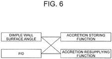
- the dimples 15 must fulfill a function for storing the accretion containing the yarn-derived lubricating component and a function for resupplying the stored accretion to the sliding surface.
- the dimples 15 serve to maintain the lubricating function realized by the accretion by taking in and storing the accretion generated during spinning and resupplying the stored accretion to the sliding surface.
- the dimple wall surface angle ⁇ and the value of P/D cannot be determined by calculation, and therefore numerical values thereof are determined by experiment. More specifically, when the dimple wall surface angle ⁇ is too large or too small, the accretion cannot be stored easily in the dimples and cannot be resupplied easily to the sliding surface. Likewise when the value of P/D is too large or too small, the accretion cannot be stored easily in the dimples and cannot be resupplied easily to the sliding surface. Therefore, the dimple wall surface angle ⁇ is preferably not less than 10° and not more than 65°, and the value of P/D is preferably not less than 1.9 and not more than 4.5.
- the accretion can be stored easily in the dimples 15, and the stored accretion can be resupplied easily to the sliding surface.
- the lubricating function realized by the accretion can be maintained in a favorable state, and as a result, the useful life of the ring/traveler system can be further extended.
- the evaluation subject component is divided into example 1, example 2, example 3, example 4, example 5, comparative example 1, comparative example 2, comparative example 3, and comparative example 4.
- the dimple sectional shape is a rounded cone shape.
- the dimple sectional shape is trapezoidal, and in comparative example 4, the dimple sectional shape is rectangular. The formation conditions of the dimples 15 will be described in detail below.
- FIG. 8A is a front view of the dimples formed under the conditions of example 1
- FIG. 8B is a sectional view of the dimples.
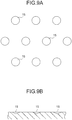
- FIG. 9A is a front view of the dimples formed under the conditions of example 2
- FIG. 9B is a sectional view of the dimples.
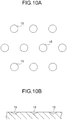
- FIG. 10A is a front view of the dimples formed under the conditions of example 3
- FIG. 10B is a sectional view of the dimples.
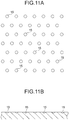
- FIG. 11A is a front view of the dimples formed under the conditions of example 4, and FIG. 11B is a sectional view of the dimples.
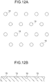
- FIG. 12A is a front view of the dimples formed under the conditions of example 5, and FIG. 12B is a sectional view of the dimples.
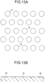
- FIG. 13A is a front view of the dimples formed under the conditions of comparative example 1
- FIG. 13B is a sectional view of the dimples.
- FIG. 14A is a front view of the dimples formed under the conditions of comparative example 2
- FIG. 14B is a sectional view of the dimples.
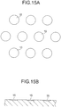
- FIG. 15A is a front view of the dimples formed under the conditions of comparative example 3
- FIG. 15B is a sectional view of the dimples.
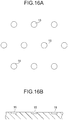
- FIG. 16A is a front view of the dimples formed under the conditions of comparative example 4, and FIG. 16B is a sectional view of the dimples.
- FIGS. 9A to 16B do not necessarily show the dimensions of the dimples at the correct scale.
- an unused traveler 12 was attached to each of the rings 11 in which the dimples 15 were formed under different conditions, as described above, and the useful life of the traveler 12 was checked in an actual machine test.
- the actual machine test was implemented in a dry condition environment using a ring spinning machine (RX240) manufactured by Toyota Industries Corporation, with the rotation speed of a spindle set at 21000 rpm. The spindle rotates integrally with the bobbin while supporting the bobbin.
- the useful life of the traveler 12 was determined on the basis of the wear level of the traveler 12. More specifically, the traveler 12 was determined to have reached the end of its useful life when the thickness of the traveler 12 decreased to half the initial thickness of the traveler 12 at the start of the test.
- the distance traveled by the traveler at the end of the useful life of the traveler 12 in an actual machine test implemented using a ring 11 not formed with the dimples 15 was set as a reference distance L (km).
- An actual machine test was then implemented for each of examples 1 to 5 and comparative examples 1 to 4, and a result obtained by dividing the distance traveled by the traveler in each example and each comparative example by the aforesaid reference distance L was set as a useful life ratio.
- examples 1 to 5 satisfy both condition 1, according to which the dimple wall surface angle ⁇ is not less than 10° and not more than 65°, and condition 2, according to which the value of P/D is not less than 1.9 and not more than 4.5.
- Comparative example 1 and comparative example 3 meanwhile, satisfy condition 1 but do not satisfy condition 2.
- Comparative example 2 satisfies neither condition 1 nor condition 2.
- Comparative example 4 satisfies condition 2 but does not satisfy condition 1.
- the useful life ratio is 1 in all of comparative examples 1 to 4. Therefore, even when the dimples 15 are formed under the conditions of comparative examples 1 to 4, the useful life of the ring/traveler system cannot be extended.
- the value of P/D is smaller than 1.8, as in comparative examples 1 and 3, the useful life of the traveler 12 does not increase even though the dimple wall surface angle ⁇ satisfies condition 1.
- the useful life of the traveler 12 does not increase when the value of P/D is larger than 4.5, as in comparative example 2.
- the value of P/D must be held within a range of not less than 1.9 and not more than 4.5.
- the useful life ratio equals or exceeds 2.
- the useful life of the ring/traveler system can be extended by a multiple of two or more in comparison with comparative examples 1 to 4.
- the useful life of the traveler 12 increases by a multiple of 3.3.
- the accretion generated during spinning is stored temporarily in the dimples 15, but when the dimples 15 are too shallow at this time, the accretion may be stored in the dimples 15 in an insufficient amount. Therefore, the dimple depth S is preferably at least 2 ⁇ m, more preferably at least 4 ⁇ m, and even more preferably at least 6 ⁇ m. Note, however, that when the dimples 15 are too deep, it may be difficult to resupply the accretion to the sliding surface. Therefore, the dimple depth S preferably satisfies a condition of being not more than 20 ⁇ m.
- the relationship between the dimple diameter and the useful life ratio is such that when the dimple diameter D is not less than 10 ⁇ m and not more than 60 ⁇ m, the useful life ratio equals or exceeds 2.
- the dimple diameter D in examples 2 and 3 in particular, in which the dimple diameter D satisfies a condition of being not less than 30 ⁇ m and not more than 60 ⁇ m, the useful life ratio equals or exceeds a multiple of 2.3.
- the dimple diameter D is preferably not less than 10 ⁇ m and not more than 60 ⁇ m, and more preferably not less than 30 ⁇ m and not more than 60 ⁇ m.
- the dimple area ratio when the dimple area ratio is compared between comparative examples 1 to 4 and examples 1 to 5, the dimple area ratio exceeds 20% in comparative examples 1 and 3 and is 3% in comparative example 2, whereas in examples 1 to 5, the dimple area ratio satisfies a condition of being not less than 4% and not more than 20%.
- the useful life ratio is at least 2 times greater than in comparative examples 1 to 4, and in examples 2 and 3 in particular, the useful life ratio equals or exceeds a multiple of 2.3.
- the dimple area ratio is preferably not less than 4% and not more than 20%, and more preferably not less than 10% and not more than 15%.
- the plurality of dimples 15 formed in the sliding surface between the ring 11 and the traveler 12 satisfy a condition according to which the dimple wall surface angle ⁇ is not less than 10° and not more than 65° and a condition according to which the value of P/D is not less than 1.9 and not more than 4.5.
- the accretion generated during spinning can be stored easily in the dimples 15, and the stored accretion can be resupplied easily to the sliding surface.
- the lubricating function realized by the accretion can be maintained in a favorable state, enabling a large reduction in wear on the components of the ring/traveler system.
- the shape and arrangement of the dimples formed in the sliding surface between the traveler and the ring can be optimized, enabling a further increase in the useful life of the ring/traveler system.
- the present invention is not limited thereto, and the plurality of dimples 15 may be arranged in a lattice shape, for example.
- spun yarn is not limited to cotton, and hemp, silk, wool, or chemical fiber (rayon, nylon, vinylon, or fleece), for example, may be used instead.
- cotton and hemp are preferable in consideration of the ease with which the accretion spreads over the sliding surface.
- the ring 11 forming the ring/traveler system is not limited to a ring including the flange 11a having a T-shaped cross-section and may be a ring including a tapered flange, for example. In this case, a traveler having a suitable shape for the tapered flange is used.
- the present invention is not limited thereto, and another processing method, such as pressing, drilling, or etching, for example, may be applied.
- a plurality of dimples are formed in a sliding surface on which a traveler and a ring slide as the traveler travels, and the plurality of dimples satisfy a condition according to which a dimple wall surface angle is not less than 10° and not more than 65° and satisfy a condition according to which a value of P/D, where P is a pitch ( ⁇ m) at which the plurality of dimples are arranged over the sliding surface and D is a diameter ( ⁇ m) of the circular open end, is not less than 1.9 and not more than 4.5.
Landscapes
- Engineering & Computer Science (AREA)
- Mechanical Engineering (AREA)
- Textile Engineering (AREA)
- Chemical & Material Sciences (AREA)
- Chemical Kinetics & Catalysis (AREA)
- Electrochemistry (AREA)
- Materials Engineering (AREA)
- Metallurgy (AREA)
- Organic Chemistry (AREA)
- Spinning Or Twisting Of Yarns (AREA)
Applications Claiming Priority (1)
| Application Number | Priority Date | Filing Date | Title |
|---|---|---|---|
| JP2018137521A JP7162459B2 (ja) | 2018-07-23 | 2018-07-23 | リング式紡機のリング/トラベラ系 |
Publications (2)
| Publication Number | Publication Date |
|---|---|
| EP3599302A1 true EP3599302A1 (fr) | 2020-01-29 |
| EP3599302B1 EP3599302B1 (fr) | 2025-08-27 |
Family
ID=67226085
Family Applications (1)
| Application Number | Title | Priority Date | Filing Date |
|---|---|---|---|
| EP19185376.1A Active EP3599302B1 (fr) | 2018-07-23 | 2019-07-10 | Système anneau/curseur pour machine à filer à anneaux |
Country Status (3)
| Country | Link |
|---|---|
| EP (1) | EP3599302B1 (fr) |
| JP (1) | JP7162459B2 (fr) |
| CN (1) | CN110760956B (fr) |
Cited By (1)
| Publication number | Priority date | Publication date | Assignee | Title |
|---|---|---|---|---|
| CN113652784A (zh) * | 2020-05-12 | 2021-11-16 | 株式会社丰田自动织机 | 细纱机用钢领及其制造方法 |
Citations (5)
| Publication number | Priority date | Publication date | Assignee | Title |
|---|---|---|---|---|
| DE102011053661A1 (de) * | 2011-09-16 | 2013-03-21 | Deutsche Institute Für Textil- Und Faserforschung Denkendorf | Fadenführungsring für eine Spinnmaschine oder eine Zwirnmaschine |
| EP2682507A2 (fr) * | 2012-07-04 | 2014-01-08 | Kabushiki Kaisha Toyota Jidoshokki | Système de curseur de machine à filer à anneaux |
| EP2933362A1 (fr) * | 2014-04-16 | 2015-10-21 | Kabushiki Kaisha Toyota Jidoshokki | Système anneau-curseur de machine à filer à anneaux |
| EP3009541A1 (fr) * | 2014-10-15 | 2016-04-20 | Kabushiki Kaisha Toyota Jidoshokki | Dispositif à anneau et curseur pour métier à filer à anneau |
| EP3009542A1 (fr) * | 2014-10-15 | 2016-04-20 | Kabushiki Kaisha Toyota Jidoshokki | Dispositif à anneau et curseur pour métier à filer à anneau |
Family Cites Families (11)
| Publication number | Priority date | Publication date | Assignee | Title |
|---|---|---|---|---|
| CH458152A (de) * | 1967-12-13 | 1968-06-15 | Rieter Ag Maschf | Befestigung für Läuferringe von Spinn- und Zwirnmaschinen |
| FR1568036A (fr) * | 1968-01-05 | 1969-05-23 | ||
| DE2939706C2 (de) * | 1979-09-29 | 1985-10-03 | Schubert & Salzer Maschinenfabrik Ag, 8070 Ingolstadt | Verfahren und Vorrichtung zum Einsetzen des Fadenabzuges an einer Offenend-Spinnvorrichtung |
| JPS6392734A (ja) * | 1986-10-01 | 1988-04-23 | Toyota Autom Loom Works Ltd | 紡機用トラベラ |
| JPH11172535A (ja) * | 1997-12-08 | 1999-06-29 | Toyota Autom Loom Works Ltd | 紡機のスピンドル |
| JP2003147646A (ja) * | 2001-11-05 | 2003-05-21 | Toyota Industries Corp | 紡機用トラベラ |
| JP4179227B2 (ja) * | 2004-05-28 | 2008-11-12 | 株式会社豊田自動織機 | 紡機における繊維束集束装置 |
| CN1912208A (zh) * | 2006-08-30 | 2007-02-14 | 徐建新 | 应用无钢丝圈的纱线卷拈装置进行卷拈纱线的方法 |
| WO2012070063A2 (fr) * | 2010-11-24 | 2012-05-31 | Lakshmi Machine Works Ltd. | Anneau de filage et de retordage textile amélioré |
| CN102409450B (zh) * | 2011-09-08 | 2013-10-23 | 西安康本材料有限公司 | 一种碳纤维加捻装置 |
| CN102493042A (zh) * | 2011-12-09 | 2012-06-13 | 江南大学 | 一种润滑环锭纺钢丝圈的装置 |
-
2018
- 2018-07-23 JP JP2018137521A patent/JP7162459B2/ja active Active
-
2019
- 2019-07-10 EP EP19185376.1A patent/EP3599302B1/fr active Active
- 2019-07-15 CN CN201910634545.0A patent/CN110760956B/zh active Active
Patent Citations (6)
| Publication number | Priority date | Publication date | Assignee | Title |
|---|---|---|---|---|
| DE102011053661A1 (de) * | 2011-09-16 | 2013-03-21 | Deutsche Institute Für Textil- Und Faserforschung Denkendorf | Fadenführungsring für eine Spinnmaschine oder eine Zwirnmaschine |
| EP2682507A2 (fr) * | 2012-07-04 | 2014-01-08 | Kabushiki Kaisha Toyota Jidoshokki | Système de curseur de machine à filer à anneaux |
| EP2933362A1 (fr) * | 2014-04-16 | 2015-10-21 | Kabushiki Kaisha Toyota Jidoshokki | Système anneau-curseur de machine à filer à anneaux |
| JP2015203175A (ja) | 2014-04-16 | 2015-11-16 | 株式会社豊田自動織機 | リング式紡機のリング/トラベラ系 |
| EP3009541A1 (fr) * | 2014-10-15 | 2016-04-20 | Kabushiki Kaisha Toyota Jidoshokki | Dispositif à anneau et curseur pour métier à filer à anneau |
| EP3009542A1 (fr) * | 2014-10-15 | 2016-04-20 | Kabushiki Kaisha Toyota Jidoshokki | Dispositif à anneau et curseur pour métier à filer à anneau |
Non-Patent Citations (3)
| Title |
|---|
| YORIKAZU SHIMOTSUMATAKUZO FUJII, JOURNAL OF TEXTILE ENGINEERING, TRAVELER BEHAVIOR IN A HIGH-SPEED RING/TRAVELER MECHANISM, vol. 22, no. 7, 1969, pages 493,499 |
| YORIKAZU SHIMOTSUMATAKUZO FUJII, JOURNAL OF TEXTILE ENGINEERING, WEAR CHARACTERISTICS AND SPEED LIMITS OF A HIGH-SPEED RING/TRAVELER MECHANISM, vol. 22, no. 11, 1969, pages 775,784 |
| YORIKAZU SHIMOTSUMATAKUZO FUJII, JOURNAL OF TEXTILE ENGINEERING, WEAR CHARACTERISTICS OF A RING/TRAVELER MECHANISM, vol. 23, no. 4, 1970, pages 267,277 |
Cited By (2)
| Publication number | Priority date | Publication date | Assignee | Title |
|---|---|---|---|---|
| CN113652784A (zh) * | 2020-05-12 | 2021-11-16 | 株式会社丰田自动织机 | 细纱机用钢领及其制造方法 |
| CN113652784B (zh) * | 2020-05-12 | 2023-09-12 | 株式会社丰田自动织机 | 细纱机用钢领及其制造方法 |
Also Published As
| Publication number | Publication date |
|---|---|
| CN110760956B (zh) | 2022-07-19 |
| EP3599302B1 (fr) | 2025-08-27 |
| CN110760956A (zh) | 2020-02-07 |
| JP2020015988A (ja) | 2020-01-30 |
| JP7162459B2 (ja) | 2022-10-28 |
Similar Documents
| Publication | Publication Date | Title |
|---|---|---|
| EP2682507B1 (fr) | Système de curseur de machine à filer à anneaux | |
| JP5910569B2 (ja) | リング式紡機のリング/トラベラ系 | |
| EP3599302B1 (fr) | Système anneau/curseur pour machine à filer à anneaux | |
| CN203977057U (zh) | 具有针舌弹起防止机构的绳状物的圆编编织机 | |
| US10385480B2 (en) | Metallic sulfide coated travelers, methods of coating travelers, and systems for use of metallic sulfide coated travelers | |
| JP6027998B2 (ja) | リング式紡機の液潤滑の無いリング/トラベラ系 | |
| EP3009541B1 (fr) | Dispositif à anneau et curseur pour métier à filer à anneau | |
| JP2014526618A (ja) | 精紡機または撚糸機に用いる糸案内リング | |
| JP7163632B2 (ja) | リング式紡機のリング/トラベラ系 | |
| JP7390969B2 (ja) | 精紡機用リングおよびその製造方法 | |
| JPH0382832A (ja) | 紡機用トラベラ | |
| EP3502325B1 (fr) | Anneau pour une machine de filature fine | |
| JP2023104661A (ja) | 合成樹脂製保持器および保持器付きころ | |
| JP2008281146A (ja) | 摺動部材 | |
| JP2007170426A (ja) | 転動装置 | |
| JPH09210066A (ja) | 含油軸受 | |
| JP2000265348A (ja) | 編組機の潤滑剤供給構造 | |
| PL226168B1 (pl) | Zelazne lozyska porowate z mikrosegmentami wykonanymi technika laserowa na ich powierzchni slizgowej |
Legal Events
| Date | Code | Title | Description |
|---|---|---|---|
| PUAI | Public reference made under article 153(3) epc to a published international application that has entered the european phase |
Free format text: ORIGINAL CODE: 0009012 |
|
| STAA | Information on the status of an ep patent application or granted ep patent |
Free format text: STATUS: REQUEST FOR EXAMINATION WAS MADE |
|
| 17P | Request for examination filed |
Effective date: 20190710 |
|
| AK | Designated contracting states |
Kind code of ref document: A1 Designated state(s): AL AT BE BG CH CY CZ DE DK EE ES FI FR GB GR HR HU IE IS IT LI LT LU LV MC MK MT NL NO PL PT RO RS SE SI SK SM TR |
|
| AX | Request for extension of the european patent |
Extension state: BA ME |
|
| STAA | Information on the status of an ep patent application or granted ep patent |
Free format text: STATUS: EXAMINATION IS IN PROGRESS |
|
| 17Q | First examination report despatched |
Effective date: 20220331 |
|
| P01 | Opt-out of the competence of the unified patent court (upc) registered |
Effective date: 20230519 |
|
| GRAP | Despatch of communication of intention to grant a patent |
Free format text: ORIGINAL CODE: EPIDOSNIGR1 |
|
| STAA | Information on the status of an ep patent application or granted ep patent |
Free format text: STATUS: GRANT OF PATENT IS INTENDED |
|
| INTG | Intention to grant announced |
Effective date: 20250401 |
|
| GRAS | Grant fee paid |
Free format text: ORIGINAL CODE: EPIDOSNIGR3 |
|
| GRAA | (expected) grant |
Free format text: ORIGINAL CODE: 0009210 |
|
| STAA | Information on the status of an ep patent application or granted ep patent |
Free format text: STATUS: THE PATENT HAS BEEN GRANTED |
|
| AK | Designated contracting states |
Kind code of ref document: B1 Designated state(s): AL AT BE BG CH CY CZ DE DK EE ES FI FR GB GR HR HU IE IS IT LI LT LU LV MC MK MT NL NO PL PT RO RS SE SI SK SM TR |
|
| REG | Reference to a national code |
Ref country code: GB Ref legal event code: FG4D |
|
| REG | Reference to a national code |
Ref country code: CH Ref legal event code: EP |
|
| REG | Reference to a national code |
Ref country code: DE Ref legal event code: R096 Ref document number: 602019074651 Country of ref document: DE |
|
| REG | Reference to a national code |
Ref country code: IE Ref legal event code: FG4D |
|
| REG | Reference to a national code |
Ref country code: NL Ref legal event code: MP Effective date: 20250827 |
|
| PG25 | Lapsed in a contracting state [announced via postgrant information from national office to epo] |
Ref country code: IS Free format text: LAPSE BECAUSE OF FAILURE TO SUBMIT A TRANSLATION OF THE DESCRIPTION OR TO PAY THE FEE WITHIN THE PRESCRIBED TIME-LIMIT Effective date: 20251227 |
|
| PG25 | Lapsed in a contracting state [announced via postgrant information from national office to epo] |
Ref country code: NO Free format text: LAPSE BECAUSE OF FAILURE TO SUBMIT A TRANSLATION OF THE DESCRIPTION OR TO PAY THE FEE WITHIN THE PRESCRIBED TIME-LIMIT Effective date: 20251127 |
|
| REG | Reference to a national code |
Ref country code: LT Ref legal event code: MG9D |
|
| PG25 | Lapsed in a contracting state [announced via postgrant information from national office to epo] |
Ref country code: PT Free format text: LAPSE BECAUSE OF FAILURE TO SUBMIT A TRANSLATION OF THE DESCRIPTION OR TO PAY THE FEE WITHIN THE PRESCRIBED TIME-LIMIT Effective date: 20251229 |
|
| PG25 | Lapsed in a contracting state [announced via postgrant information from national office to epo] |
Ref country code: FI Free format text: LAPSE BECAUSE OF FAILURE TO SUBMIT A TRANSLATION OF THE DESCRIPTION OR TO PAY THE FEE WITHIN THE PRESCRIBED TIME-LIMIT Effective date: 20250827 |
|
| PG25 | Lapsed in a contracting state [announced via postgrant information from national office to epo] |
Ref country code: NL Free format text: LAPSE BECAUSE OF FAILURE TO SUBMIT A TRANSLATION OF THE DESCRIPTION OR TO PAY THE FEE WITHIN THE PRESCRIBED TIME-LIMIT Effective date: 20250827 Ref country code: HR Free format text: LAPSE BECAUSE OF FAILURE TO SUBMIT A TRANSLATION OF THE DESCRIPTION OR TO PAY THE FEE WITHIN THE PRESCRIBED TIME-LIMIT Effective date: 20250827 |
|
| PG25 | Lapsed in a contracting state [announced via postgrant information from national office to epo] |
Ref country code: GR Free format text: LAPSE BECAUSE OF FAILURE TO SUBMIT A TRANSLATION OF THE DESCRIPTION OR TO PAY THE FEE WITHIN THE PRESCRIBED TIME-LIMIT Effective date: 20251128 |
|
| PG25 | Lapsed in a contracting state [announced via postgrant information from national office to epo] |
Ref country code: SE Free format text: LAPSE BECAUSE OF FAILURE TO SUBMIT A TRANSLATION OF THE DESCRIPTION OR TO PAY THE FEE WITHIN THE PRESCRIBED TIME-LIMIT Effective date: 20250827 |
|
| PG25 | Lapsed in a contracting state [announced via postgrant information from national office to epo] |
Ref country code: LV Free format text: LAPSE BECAUSE OF FAILURE TO SUBMIT A TRANSLATION OF THE DESCRIPTION OR TO PAY THE FEE WITHIN THE PRESCRIBED TIME-LIMIT Effective date: 20250827 |
|
| PG25 | Lapsed in a contracting state [announced via postgrant information from national office to epo] |
Ref country code: PL Free format text: LAPSE BECAUSE OF FAILURE TO SUBMIT A TRANSLATION OF THE DESCRIPTION OR TO PAY THE FEE WITHIN THE PRESCRIBED TIME-LIMIT Effective date: 20250827 Ref country code: BG Free format text: LAPSE BECAUSE OF FAILURE TO SUBMIT A TRANSLATION OF THE DESCRIPTION OR TO PAY THE FEE WITHIN THE PRESCRIBED TIME-LIMIT Effective date: 20250827 |
|
| PG25 | Lapsed in a contracting state [announced via postgrant information from national office to epo] |
Ref country code: RS Free format text: LAPSE BECAUSE OF FAILURE TO SUBMIT A TRANSLATION OF THE DESCRIPTION OR TO PAY THE FEE WITHIN THE PRESCRIBED TIME-LIMIT Effective date: 20251127 |
|
| PG25 | Lapsed in a contracting state [announced via postgrant information from national office to epo] |
Ref country code: ES Free format text: LAPSE BECAUSE OF FAILURE TO SUBMIT A TRANSLATION OF THE DESCRIPTION OR TO PAY THE FEE WITHIN THE PRESCRIBED TIME-LIMIT Effective date: 20250827 |
|
| REG | Reference to a national code |
Ref country code: AT Ref legal event code: MK05 Ref document number: 1830039 Country of ref document: AT Kind code of ref document: T Effective date: 20250827 |
|
| PG25 | Lapsed in a contracting state [announced via postgrant information from national office to epo] |
Ref country code: SM Free format text: LAPSE BECAUSE OF FAILURE TO SUBMIT A TRANSLATION OF THE DESCRIPTION OR TO PAY THE FEE WITHIN THE PRESCRIBED TIME-LIMIT Effective date: 20250827 |
|
| PG25 | Lapsed in a contracting state [announced via postgrant information from national office to epo] |
Ref country code: DK Free format text: LAPSE BECAUSE OF FAILURE TO SUBMIT A TRANSLATION OF THE DESCRIPTION OR TO PAY THE FEE WITHIN THE PRESCRIBED TIME-LIMIT Effective date: 20250827 |
|
| PG25 | Lapsed in a contracting state [announced via postgrant information from national office to epo] |
Ref country code: AT Free format text: LAPSE BECAUSE OF FAILURE TO SUBMIT A TRANSLATION OF THE DESCRIPTION OR TO PAY THE FEE WITHIN THE PRESCRIBED TIME-LIMIT Effective date: 20250827 |
|
| PG25 | Lapsed in a contracting state [announced via postgrant information from national office to epo] |
Ref country code: IT Free format text: LAPSE BECAUSE OF FAILURE TO SUBMIT A TRANSLATION OF THE DESCRIPTION OR TO PAY THE FEE WITHIN THE PRESCRIBED TIME-LIMIT Effective date: 20250827 |
|
| PG25 | Lapsed in a contracting state [announced via postgrant information from national office to epo] |
Ref country code: CZ Free format text: LAPSE BECAUSE OF FAILURE TO SUBMIT A TRANSLATION OF THE DESCRIPTION OR TO PAY THE FEE WITHIN THE PRESCRIBED TIME-LIMIT Effective date: 20250827 |
|
| PG25 | Lapsed in a contracting state [announced via postgrant information from national office to epo] |
Ref country code: EE Free format text: LAPSE BECAUSE OF FAILURE TO SUBMIT A TRANSLATION OF THE DESCRIPTION OR TO PAY THE FEE WITHIN THE PRESCRIBED TIME-LIMIT Effective date: 20250827 Ref country code: SK Free format text: LAPSE BECAUSE OF FAILURE TO SUBMIT A TRANSLATION OF THE DESCRIPTION OR TO PAY THE FEE WITHIN THE PRESCRIBED TIME-LIMIT Effective date: 20250827 |