EP3600679B1 - Séparateur à vidange automatique pour l'évacuation en douceur de produits sensibles au cisaillement et procédé pour le faire fonctionner - Google Patents
Séparateur à vidange automatique pour l'évacuation en douceur de produits sensibles au cisaillement et procédé pour le faire fonctionner Download PDFInfo
- Publication number
- EP3600679B1 EP3600679B1 EP18710435.1A EP18710435A EP3600679B1 EP 3600679 B1 EP3600679 B1 EP 3600679B1 EP 18710435 A EP18710435 A EP 18710435A EP 3600679 B1 EP3600679 B1 EP 3600679B1
- Authority
- EP
- European Patent Office
- Prior art keywords
- separator
- solid
- solids
- emptying
- self
- Prior art date
- Legal status (The legal status is an assumption and is not a legal conclusion. Google has not performed a legal analysis and makes no representation as to the accuracy of the status listed.)
- Active
Links
Images


Classifications
-
- B—PERFORMING OPERATIONS; TRANSPORTING
- B04—CENTRIFUGAL APPARATUS OR MACHINES FOR CARRYING-OUT PHYSICAL OR CHEMICAL PROCESSES
- B04B—CENTRIFUGES
- B04B7/00—Elements of centrifuges
- B04B7/02—Casings; Lids
- B04B7/04—Casings facilitating discharge
-
- B—PERFORMING OPERATIONS; TRANSPORTING
- B04—CENTRIFUGAL APPARATUS OR MACHINES FOR CARRYING-OUT PHYSICAL OR CHEMICAL PROCESSES
- B04B—CENTRIFUGES
- B04B1/00—Centrifuges with rotary bowls provided with solid jackets for separating predominantly liquid mixtures with or without solid particles
- B04B1/10—Centrifuges with rotary bowls provided with solid jackets for separating predominantly liquid mixtures with or without solid particles with discharging outlets in the plane of the maximum diameter of the bowl
-
- B—PERFORMING OPERATIONS; TRANSPORTING
- B04—CENTRIFUGAL APPARATUS OR MACHINES FOR CARRYING-OUT PHYSICAL OR CHEMICAL PROCESSES
- B04B—CENTRIFUGES
- B04B1/00—Centrifuges with rotary bowls provided with solid jackets for separating predominantly liquid mixtures with or without solid particles
- B04B1/10—Centrifuges with rotary bowls provided with solid jackets for separating predominantly liquid mixtures with or without solid particles with discharging outlets in the plane of the maximum diameter of the bowl
- B04B1/12—Centrifuges with rotary bowls provided with solid jackets for separating predominantly liquid mixtures with or without solid particles with discharging outlets in the plane of the maximum diameter of the bowl with continuous discharge
-
- B—PERFORMING OPERATIONS; TRANSPORTING
- B04—CENTRIFUGAL APPARATUS OR MACHINES FOR CARRYING-OUT PHYSICAL OR CHEMICAL PROCESSES
- B04B—CENTRIFUGES
- B04B1/00—Centrifuges with rotary bowls provided with solid jackets for separating predominantly liquid mixtures with or without solid particles
- B04B1/10—Centrifuges with rotary bowls provided with solid jackets for separating predominantly liquid mixtures with or without solid particles with discharging outlets in the plane of the maximum diameter of the bowl
- B04B1/14—Centrifuges with rotary bowls provided with solid jackets for separating predominantly liquid mixtures with or without solid particles with discharging outlets in the plane of the maximum diameter of the bowl with periodical discharge
-
- B—PERFORMING OPERATIONS; TRANSPORTING
- B04—CENTRIFUGAL APPARATUS OR MACHINES FOR CARRYING-OUT PHYSICAL OR CHEMICAL PROCESSES
- B04B—CENTRIFUGES
- B04B11/00—Feeding, charging, or discharging bowls
- B04B11/02—Continuous feeding or discharging; Control arrangements therefor
-
- B—PERFORMING OPERATIONS; TRANSPORTING
- B04—CENTRIFUGAL APPARATUS OR MACHINES FOR CARRYING-OUT PHYSICAL OR CHEMICAL PROCESSES
- B04B—CENTRIFUGES
- B04B11/00—Feeding, charging, or discharging bowls
- B04B11/04—Periodical feeding or discharging; Control arrangements therefor
Definitions
- the invention relates to a device according to the preamble of claim 1 and a corresponding method.
- Self-draining separators are used to clarify a product to be processed from substances with a higher specific gravity - hereinafter referred to as solids - and are known from the prior art.
- Such a separator then has a rotatable drum with an inlet, at least one liquid outlet, solids outlet openings that can be opened and closed discontinuously or solids outlet openings that are continuously open, and a control unit.
- the solids outlet openings usually open into an annular space, which is also referred to as a solids trap
- a self-draining separator is described.
- the separator has a solids catcher with an annular baffle.
- the baffle wall is designed so that the discharged solids travel a defined path along a curved path before being discharged from the solids catcher. This is intended to ensure gentle and low-shear deflection of the solids from the solids outlet openings of the separator into the solids catcher.
- a generic separator according to the preamble of claim 1 is also from DE 10 2013 111 576 A known.
- the invention has the task of further developing the generic self-emptying separator in such a way that it enables gentle and non-destructive solids discharge.
- the invention solves this problem through the subject matter of claim 1.
- the invention further creates the method of claim 10.
- the solids catcher has a device for generating a fluid curtain onto which the solids emerging from the outlet openings for solids strike before they could hit a solid wall in the solids catcher.
- the momentum of the escaping solid is advantageously at least partially reduced when it hits the fluid curtain, so that the solid is discharged into the solids catcher gently and with little shear.
- a method for operating a separator according to one of the related claims is created, with which a product to be processed is cleared of solid in a centrifugal field in the drum, which is continuously or discontinuously emptied from the drum through outlet openings, and in which at least during When the solids are emptied, a fluid curtain is created, onto which the solids emerging from the outlet openings for solids impinge.
- the device for generating a fluid curtain has openings, ie nozzles, which are distributed around the circumference of the solids catcher and with which the fluid curtain can be generated. This advantageously ensures that the components required for gentle and low-shear solids discharge can be easily arranged on a separator without converting the solids catcher or can even be retrofitted.
- the fluid curtain is preferably created in such a way that it During the solids discharge, it extends cylindrically or conically around the drum or at least concentrically in a sleeve-like manner around its solids discharge openings.
- the solids catcher has a baffle wall which is arranged behind the curtain in the direction of flight of the solids.
- the separator can thus be used either with or without a fluid curtain.
- the fluid curtain prefferably be formed along the entire circumference of the solids trap in front of a baffle wall.
- the fluid curtain can be used on a separator that discontinuously empties the solid.
- the fluid curtain is an advantageous addition.
- water can be used as the fluid that forms the fluid curtain.
- the fluid curtain is then a water curtain made of liquid water.
- the use of the starting product to be processed or its obtained clear phase as a fluid for the fluid curtain is also advantageous since this does not cause the solid to mix with an additional fluid.
- the fluid curtain can only be switched on shortly before emptying, time on ⁇ 10 seconds, or switched off again immediately after emptying, time off ⁇ 10 seconds.
- Time out can also be significantly increased Time out ⁇ 10 minutes to ensure that the solid is flushed out of the solids catcher.
- Fig. 1 shows a separator 1 for clarifying solids-containing, flowable starting products AP with a rotatable drum 2 with a vertical axis of rotation. The processing of the starting product AP takes place in continuous operation.
- the separator 1 is a self-draining separator 1.
- the drum 2 of the separator 1 in the form of a self-emptying separator 1, has a here discontinuous solids outlet, the solid F separated from the starting product AP by clarification being removed here at intervals by opening and re-closing outlet nozzles or outlet openings 3.
- the drum 2 has a drum base 4 and a drum cover 5. It is also preferably surrounded by a hood 6.
- the drum 2 is also placed on a drive spindle 7, which is rotatably mounted and can be driven by a motor.
- the drum 2 has a product inlet 8 through which the starting product AP is passed into the drum 2. It also has at least one process 9 - provided with a gripper - which serves to derive a clear phase KP from the drum 2.
- the gripper - also called a peeling disk - is a centripetal pump.
- the process 9 can also be carried out constructively in a different way or with other means. In addition to the clarification, it is also conceivable to separate the starting product AP into two liquid phases of different densities. For this purpose, another liquid drain is required.
- the drum 2 preferably has a plate pack 10 made of axially spaced separating plates.
- a solids collecting space 11 is formed between the outer circumference of the plate pack 10 and the inner circumference of the drum 2 in the area of its largest inner diameter. Solids, which are separated from the clear phase in the area of the plate stack 10, collect in the solids collecting space 11, from which the solids F can be discharged from the drum 2 via outlet openings 3.
- the outlet openings 3 can be opened and closed here by means of a piston slide 12, which is arranged in the lower drum part 4 and can be displaced parallel to the axis of rotation (in particular vertically).
- a piston slide 12 which is arranged in the lower drum part 4 and can be displaced parallel to the axis of rotation (in particular vertically).
- the drum 2 has an actuating mechanism.
- this includes at least one inlet line 14 for a control fluid such as water and a valve arrangement 15 in the drum 2 and further elements outside the drum 2.
- the inlet of the control fluid is thus made possible via a metering arrangement 16 arranged outside the drum 2, which is one outside the Drum 2 arranged inlet line 17 for the control fluid is assigned, so that for a solids emptying of the solid F by releasing the valve arrangement 15, the control fluid can be introduced into the drum 2 or, conversely, the inflow of control fluid can be interrupted in order to move the piston slide 12 accordingly, to release the outlet openings 3.
- the solids catcher 13 has a device for generating a fluid curtain 20 on which the solids F emerging from the outlet openings 3 for solids F impinge.
- the solids catcher 13 also has at least one baffle wall 18, which is preferably radially outer with respect to the axis of rotation.
- the device for generating a fluid curtain 20 has several, preferably four or more openings - in particular nozzles 19 - which can be distributed angularly spaced - preferably uniformly - on the circumference of the solids catcher 13.
- the fluid curtain 20 is located radially on the inside relative to the baffle wall 18.
- the number of openings, in particular nozzles, 19 depends on the diameter of the drum 2 and is advantageously chosen so that the fluid curtain 20 is generated through the openings, in particular nozzles, 19 in such a way that it advantageously extends along the entire circumference of the solids catcher 13 its baffle wall 18 is formed.
- the momentum of the emerging solid F is thereby advantageously at least partially reduced when it hits the fluid curtain 20.
- the fluid curtain 20 is preferably sprayed from top to bottom in the axial direction with a vertical axis of rotation. Then the openings 19 are preferably distributed on an upper wall of the solids trap or on an adjacent component such as a hood and their outlet end is preferably directed axially essentially downwards.
- the fluid curtain 20 is cylindrical or conical in the produced state. But it can, for example, also surround the drum in a polygonal manner.
- the openings 19 are preferably distributed on an upper wall of the solids catcher and their outlet end is directed downwards.
- the openings, in particular nozzles, 19 are preferably designed in such a way that the emerging fluid emerges in a fan-like manner, that is to say the fluid jet is narrow radially in relation to the axis of rotation of the drum, and perpendicular to this the fluid jet is wide in order to achieve the entirety with as few openings, in particular nozzles, as possible
- the nozzle can have a slot-like outlet opening be provided or alternatively with several outlet openings in the direction of the fluid curtain to be generated.
- the effectiveness of the fluid curtain can be adjusted by the amount/time of fluid used depending on the sensitivity of the product to be processed. The more fluid is used, the denser the fluid curtain becomes and the more the momentum of the escaping solid is reduced.
- the amount/time of the fluid can be regulated in the actuator 22 by changing the opening cross section of a valve.
- the pressure of the fluid in the line 21 can be changed, or the cross sections of the openings in the openings, in particular nozzles, 19 can be adjusted.
- the openings, in particular nozzles, 19 can, as in Fig. 1 and Fig. 2 shown, the fluid can be directed into the solids catcher from above; alternatively, this is also possible from below or tangentially from the direction of the baffle wall 18.
- the fluid forming the fluid curtain 20 is preferably water. This is advantageous because water hydraulics can also be present for actuating the piston slide 12 and parts of this hydraulic system can therefore be used multiple times. However, this is not mandatory.
- the use of the starting product to be processed or its obtained clear phase as a fluid for the fluid curtain is also advantageous, as this does not result in the solid being mixed with an additional fluid.
- the fluid is supplied via a corresponding line 21.
- the line 21 can be shut off and opened by a control pulse from an actuator 22.
- the fluid curtain 20 can only be switched on shortly before the solid is emptied.
- the switch-on time before emptying can be “Time on ⁇ 10 seconds”.
- the fluid curtain is preferably switched off again immediately after emptying.
- Time out can also be significantly increased Time out ⁇ 10 minutes to ensure that the solid is flushed out of the solids catcher.
- the fluid curtain can also be permanently activated.
- the fluid curtain 20 extending in front of the baffle wall 18 simply advantageously enables gentle and low-shear momentum reduction of the solid F emerging from the outlet openings 3 of the separator 1 into the solids catcher 13.
- the components 19, 21, 22 required for this can be retrofitted to a separator 1 easily and without converting the solids catcher 13.
- the constructive variant management of the separator 1 is simplified, since the variant of the solids catcher 13 for gentle solids discharge is simple and therefore advantageously formed by the usual variant of the solids catcher 13 plus the openings, in particular nozzles, 19.
- control device 23 is connected to the actuators or valves 16, 21 via data connections 24, 25, which are implemented here, for example, by live or signal-carrying lines or cables.
- the data connections 24, 25 can alternatively be implemented using other suitable operating principles, such as bridging the signal path with high-frequency radiation, such as radio signals.
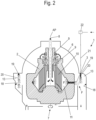
- the separator is 1 in Fig. 2 only deviations, changes or additions to the separator 1 Fig. 1 described.
- the separator 1 reworks Fig. 2 , which does not fall under claim 1, as a self-draining separator 1 with a continuous solids outlet.
- the drum 2 of the separator 1 here has a continuous solids outlet, with the solid F separated from the starting product AP by clarification being permanently removed here through the outlet nozzles or outlet openings 3.
- a piston slide 12 with the corresponding actuators and supply lines is therefore not required here.
- FIG. 2 the openings, in particular nozzles, 19, which create the fluid curtain 20 in front of the baffle wall 18 of the solids catcher 13, are clearly shown.
- the solids catcher 13 here has a line with which the solids F is drained from the solids catcher 13. For this reason, the solids catcher 13 in the in Fig. 2
- the sectional view shown - where the section is placed through the derivation - has two different geometries.
- the starting product AP is preferably continuously fed into the drum 2 of the separator, where it is clarified. There is a continuous clear phase outlet of the clear phase KP.
- step 100 the emptying of the solid F from the solids collecting space 11 of the separator is initiated or, in the case of a continuously emptying separator 1, the separation process is started.
- step 200 the supply of fluid to the openings, in particular nozzles, 19 to generate the fluid curtain 20 in front of the baffle wall 18 of the solids catcher 13 is started by a control pulse on the actuator 22.
- a defined, discrete time interval elapses, which is determined according to the emptying duration and can be, for example, one to ten, particularly preferably three to five second(s).
- the fluid curtain is built.
- step 400 the emptying of the solid F from the solids collecting space 11 of the separator is started by a control pulse on the metering arrangement 16 and the valve arrangement 15, provided that the separator is a discontinuously emptying separator Fig. 1 acts.
- the emptying of the solid F begins immediately after the separation process has been started and the time interval in step 300 has elapsed.
- a subsequent step 500 the discharge of solid F from the solids collecting space 11 is ended by a control pulse on the metering arrangement 16 and the valve arrangement 15.
- the emptying of the solid F only ends when the separation process is ended.
- a final step 600 the supply of fluid to the openings, in particular nozzles, 19 for generating the fluid curtain 20 in front of the baffle wall 18 of the solids catcher 13 is ended by a control pulse on the actuator 22.
- the illustrated and claimed methods ensure gentle and low-shear emptying of solid F from a separator 1 according to the invention which discontinuously empties the solid F in a simple and therefore advantageous manner.
Landscapes
- Centrifugal Separators (AREA)
Claims (10)
- Séparateur à vidange automatique (1) comprenant un tambour rotatif (2) avec une arrivée (8), avec au moins un écoulement de liquide (9) muni d'ouvertures de sortie (3) pour des solides (F), et une commande (23), dans lequel un produit de départ fluide (AP) est débarrassé des solides (F) en fonctionnement continu dans un champ centrifuge dans le tambour (2) en rotation, dans lequel au moins une phase liquide clarifiée ou phase claire (KP) sort en continu et dans lequel une phase solide (F) sort de manière discontinue par les ouvertures de sortie (3) (on parle de vidange des solides) d'un espace d'accumulation des solides (11) du tambour (2) dans un collecteur de solides (13), de sorte que le séparateur (1) est un séparateur (1) à vidange discontinue des solides (F), caractérisé en ce que le collecteur de solides (13) présente un dispositif pour la création d'un rideau de fluide (20) que les solides (F) sortant des ouvertures de sortie (3) pour les solides (F) viennent toucher, le dispositif pour la création d'un rideau de fluide (20) présentant des ouvertures, les ouvertures (19) étant réparties sur une paroi supérieure du collecteur de solides ou sur un composant contigu tel qu'un capot et leur extrémité de sortie étant orientée sensiblement vers le bas dans le sens axial, les ouvertures étant des buses (19) et les buses (19) étant réparties sur la circonférence du collecteur de solides (13).
- Séparateur à vidange automatique (1) selon la revendication 1, caractérisé en ce qu'au moins quatre ou plusieurs ouvertures, en particulier buses (19), sont réparties sur la circonférence du collecteur de solides (13).
- Séparateur à vidange automatique (1) selon l'une des revendications précédentes, caractérisé en ce que le collecteur de solides (13) présente une paroi d'impact (18)
- Séparateur à vidange automatique (1) selon l'une des revendications précédentes, caractérisé en ce que le rideau de fluide (20) est formé sur toute la circonférence du collecteur de solides (13) devant sa paroi d'impact (18).
- Séparateur à vidange automatique (1) selon l'une des revendications 1 à 4, caractérisé en ce que le séparateur (1) est un séparateur (1) à vidange de solides (F) continue.
- Séparateur à vidange automatique (1) selon l'une des revendications précédentes, caractérisé en ce que le fluide formant le rideau de fluide (20) est de l'eau.
- Séparateur à vidange automatique (1) selon l'une des revendications précédentes, caractérisé en ce qu'il utilise comme fluide formant le rideau de fluide (20) le produit de départ ou une des phases claires extraites du produit de départ à traiter.
- Séparateur à vidange automatique (1) selon l'une des revendications précédentes, caractérisé en ce que l'arrivée du fluide vers les ouvertures, en particulier les buses (19), passe par une conduite d'arrivée (21), laquelle conduite d'arrivée (21) peut être fermée et ouverte par un organe de manoeuvre (22).
- Séparateur à vidange automatique (1) selon l'une des revendications précédentes, caractérisé en ce qu'il est prévu un dispositif de commande (23) qui est relié de préférence par des liaisons de données (24, 25) à l'organe de manoeuvre (22).
- Procédé de conduite d'un séparateur selon l'une des revendications précédentes, avec lequel un produit à traiter est débarrassé des solides dans un champ centrifuge dans le tambour, lesquels solides sont vidés de façon discontinue hors du tambour, caractérisé en ce qu'est créé, au moins pendant la vidange des solides, un rideau de fluide que les solides (F) sortant des ouvertures de sortie (3) pour les solides (F) viennent toucher.
Applications Claiming Priority (2)
| Application Number | Priority Date | Filing Date | Title |
|---|---|---|---|
| DE102017106801.5A DE102017106801B3 (de) | 2017-03-29 | 2017-03-29 | Selbstentleerender Separator zum schonenden Austrag von scherempfindlichen Produkten sowie Verfahren zu seinem Betrieb |
| PCT/EP2018/055726 WO2018177710A1 (fr) | 2017-03-29 | 2018-03-08 | Séparateur à vidange automatique pour l'évacuation en douceur de produits sensibles au cisaillement et procédé pour le faire fonctionner |
Publications (2)
| Publication Number | Publication Date |
|---|---|
| EP3600679A1 EP3600679A1 (fr) | 2020-02-05 |
| EP3600679B1 true EP3600679B1 (fr) | 2023-09-13 |
Family
ID=61622584
Family Applications (1)
| Application Number | Title | Priority Date | Filing Date |
|---|---|---|---|
| EP18710435.1A Active EP3600679B1 (fr) | 2017-03-29 | 2018-03-08 | Séparateur à vidange automatique pour l'évacuation en douceur de produits sensibles au cisaillement et procédé pour le faire fonctionner |
Country Status (5)
| Country | Link |
|---|---|
| US (1) | US11389809B2 (fr) |
| EP (1) | EP3600679B1 (fr) |
| CN (1) | CN110520220B (fr) |
| DE (1) | DE102017106801B3 (fr) |
| WO (1) | WO2018177710A1 (fr) |
Families Citing this family (2)
| Publication number | Priority date | Publication date | Assignee | Title |
|---|---|---|---|---|
| TWI697353B (zh) * | 2019-08-07 | 2020-07-01 | 長泰精密有限公司 | 油水分離機分離筒上蓋裝置 |
| DE102020128748A1 (de) * | 2020-11-02 | 2022-05-05 | Gea Westfalia Separator Group Gmbh | Separator |
Family Cites Families (6)
| Publication number | Priority date | Publication date | Assignee | Title |
|---|---|---|---|---|
| US3145172A (en) * | 1959-07-09 | 1964-08-18 | Separator Ab | Flushing device for centrifugal separators |
| DE2550496B2 (de) * | 1975-11-11 | 1980-12-04 | Braunschweigische Maschinenbauanstalt, 3300 Braunschweig | Verfahren und Zentrifuge zum Abschleudern und Wiederauflösen von Zucker |
| DE2755130A1 (de) * | 1977-12-10 | 1979-06-13 | Selwig & Lange Maschf | Verfahren und vorrichtung zum einmaischen von zuckerkristallen |
| SE509400C2 (sv) * | 1996-01-02 | 1999-01-25 | Noxon Ab | Dekanteringscentrifug |
| DE10135317A1 (de) | 2001-07-19 | 2003-01-30 | Bayer Ag | Umlenkring für eine selbstaustragende Zentrifuge |
| DE102013111576A1 (de) * | 2013-10-21 | 2015-04-23 | Gea Mechanical Equipment Gmbh | Verfahren zur Klärung eines fließfähigen Produktes mit einer Zentrifuge, insbesondere einem Separator |
-
2017
- 2017-03-29 DE DE102017106801.5A patent/DE102017106801B3/de active Active
-
2018
- 2018-03-08 WO PCT/EP2018/055726 patent/WO2018177710A1/fr not_active Ceased
- 2018-03-08 EP EP18710435.1A patent/EP3600679B1/fr active Active
- 2018-03-08 CN CN201880021958.5A patent/CN110520220B/zh active Active
- 2018-03-08 US US16/498,540 patent/US11389809B2/en active Active
Also Published As
| Publication number | Publication date |
|---|---|
| DE102017106801B3 (de) | 2018-08-02 |
| CN110520220B (zh) | 2022-01-14 |
| EP3600679A1 (fr) | 2020-02-05 |
| US20200038882A1 (en) | 2020-02-06 |
| US11389809B2 (en) | 2022-07-19 |
| CN110520220A (zh) | 2019-11-29 |
| WO2018177710A1 (fr) | 2018-10-04 |
Similar Documents
| Publication | Publication Date | Title |
|---|---|---|
| EP3426405B1 (fr) | Séparateur | |
| EP3930909B1 (fr) | Séparateur | |
| DE19907067C2 (de) | Trennvorrichtung für das Aussondern von Feststoffen aus einem Flüssigkeits-Feststoff-Gemisch | |
| EP2484451A2 (fr) | Centrifugeuse à bol plein dotée d'un séchage du gâteau de matière sèche | |
| DE10340366B4 (de) | Filtervorrichtung | |
| DE102017106801B3 (de) | Selbstentleerender Separator zum schonenden Austrag von scherempfindlichen Produkten sowie Verfahren zu seinem Betrieb | |
| WO2007074076A1 (fr) | Centrifugeuse a vis sans fin a bol plein | |
| EP3328550A1 (fr) | Tambour de séparateur et séparateur | |
| WO2016034626A1 (fr) | Séparateur et procédé pour séparer des particules d'un flux de gaz | |
| WO2018224400A1 (fr) | Procédé de vidange de matière solide d'une centrifugeuse | |
| EP0927579A2 (fr) | Procédé et dispositif pour extraire des solides d' un mélange solide- liquide | |
| WO2007104455A1 (fr) | Centrifugeuse comportant un tube d'alimentation | |
| EP4237157B1 (fr) | Séparateur | |
| DE10200599A1 (de) | Vorrichtung zum Abscheiden von organischem und anorganischem Material aus einer Flüssigkeit | |
| DE202010005476U1 (de) | Separator | |
| EP3570981B1 (fr) | Centrifugeuse | |
| EP0692311B1 (fr) | Centrifugeuse travaillant en continu pour la centrifugation de masses cuites | |
| EP4475996B1 (fr) | Séparateur | |
| DE102008009253A1 (de) | Schälvorrichtung zum Abschälen eines Feststoffkuchenmaterials von der Innenseite einer Trommel einer Zentrifuge | |
| DE102010016740B4 (de) | Düsenseparator und Verfahren zum Ableiten einer Feststoffphase aus dem Düsenseparator | |
| WO2010007057A1 (fr) | Dispositif et procédé destinés à retirer des fluides et/ou des solides | |
| DE102022124097A1 (de) | Verfahren zur Reinigung eines Separators | |
| WO2021121454A1 (fr) | Procédé de nettoyage d'eau de lavage usée, et dispositif de nettoyage pour la mise en œuvre du procédé | |
| DE3044797A1 (de) | Verfahren und vorrichtung zum mechanischen trennen von feststoffteilen aus fluessigkeiten durch zentrifugieren | |
| DE2013865A1 (de) | Zentrifuge |
Legal Events
| Date | Code | Title | Description |
|---|---|---|---|
| STAA | Information on the status of an ep patent application or granted ep patent |
Free format text: STATUS: UNKNOWN |
|
| STAA | Information on the status of an ep patent application or granted ep patent |
Free format text: STATUS: THE INTERNATIONAL PUBLICATION HAS BEEN MADE |
|
| PUAI | Public reference made under article 153(3) epc to a published international application that has entered the european phase |
Free format text: ORIGINAL CODE: 0009012 |
|
| STAA | Information on the status of an ep patent application or granted ep patent |
Free format text: STATUS: REQUEST FOR EXAMINATION WAS MADE |
|
| 17P | Request for examination filed |
Effective date: 20191002 |
|
| AK | Designated contracting states |
Kind code of ref document: A1 Designated state(s): AL AT BE BG CH CY CZ DE DK EE ES FI FR GB GR HR HU IE IS IT LI LT LU LV MC MK MT NL NO PL PT RO RS SE SI SK SM TR |
|
| AX | Request for extension of the european patent |
Extension state: BA ME |
|
| DAV | Request for validation of the european patent (deleted) | ||
| DAX | Request for extension of the european patent (deleted) | ||
| GRAP | Despatch of communication of intention to grant a patent |
Free format text: ORIGINAL CODE: EPIDOSNIGR1 |
|
| STAA | Information on the status of an ep patent application or granted ep patent |
Free format text: STATUS: GRANT OF PATENT IS INTENDED |
|
| INTG | Intention to grant announced |
Effective date: 20230406 |
|
| GRAJ | Information related to disapproval of communication of intention to grant by the applicant or resumption of examination proceedings by the epo deleted |
Free format text: ORIGINAL CODE: EPIDOSDIGR1 |
|
| STAA | Information on the status of an ep patent application or granted ep patent |
Free format text: STATUS: REQUEST FOR EXAMINATION WAS MADE |
|
| GRAS | Grant fee paid |
Free format text: ORIGINAL CODE: EPIDOSNIGR3 |
|
| STAA | Information on the status of an ep patent application or granted ep patent |
Free format text: STATUS: GRANT OF PATENT IS INTENDED |
|
| GRAP | Despatch of communication of intention to grant a patent |
Free format text: ORIGINAL CODE: EPIDOSNIGR1 |
|
| GRAA | (expected) grant |
Free format text: ORIGINAL CODE: 0009210 |
|
| STAA | Information on the status of an ep patent application or granted ep patent |
Free format text: STATUS: THE PATENT HAS BEEN GRANTED |
|
| INTG | Intention to grant announced |
Effective date: 20230803 |
|
| AK | Designated contracting states |
Kind code of ref document: B1 Designated state(s): AL AT BE BG CH CY CZ DE DK EE ES FI FR GB GR HR HU IE IS IT LI LT LU LV MC MK MT NL NO PL PT RO RS SE SI SK SM TR |
|
| P01 | Opt-out of the competence of the unified patent court (upc) registered |
Effective date: 20230809 |
|
| REG | Reference to a national code |
Ref country code: GB Ref legal event code: FG4D Free format text: NOT ENGLISH |
|
| REG | Reference to a national code |
Ref country code: CH Ref legal event code: EP |
|
| REG | Reference to a national code |
Ref country code: DE Ref legal event code: R096 Ref document number: 502018013246 Country of ref document: DE |
|
| REG | Reference to a national code |
Ref country code: IE Ref legal event code: FG4D Free format text: LANGUAGE OF EP DOCUMENT: GERMAN |
|
| REG | Reference to a national code |
Ref country code: SE Ref legal event code: TRGR |
|
| REG | Reference to a national code |
Ref country code: LT Ref legal event code: MG9D |
|
| REG | Reference to a national code |
Ref country code: NL Ref legal event code: MP Effective date: 20230913 |
|
| PG25 | Lapsed in a contracting state [announced via postgrant information from national office to epo] |
Ref country code: GR Free format text: LAPSE BECAUSE OF FAILURE TO SUBMIT A TRANSLATION OF THE DESCRIPTION OR TO PAY THE FEE WITHIN THE PRESCRIBED TIME-LIMIT Effective date: 20231214 |
|
| PG25 | Lapsed in a contracting state [announced via postgrant information from national office to epo] |
Ref country code: RS Free format text: LAPSE BECAUSE OF FAILURE TO SUBMIT A TRANSLATION OF THE DESCRIPTION OR TO PAY THE FEE WITHIN THE PRESCRIBED TIME-LIMIT Effective date: 20230913 Ref country code: NO Free format text: LAPSE BECAUSE OF FAILURE TO SUBMIT A TRANSLATION OF THE DESCRIPTION OR TO PAY THE FEE WITHIN THE PRESCRIBED TIME-LIMIT Effective date: 20231213 Ref country code: LV Free format text: LAPSE BECAUSE OF FAILURE TO SUBMIT A TRANSLATION OF THE DESCRIPTION OR TO PAY THE FEE WITHIN THE PRESCRIBED TIME-LIMIT Effective date: 20230913 Ref country code: LT Free format text: LAPSE BECAUSE OF FAILURE TO SUBMIT A TRANSLATION OF THE DESCRIPTION OR TO PAY THE FEE WITHIN THE PRESCRIBED TIME-LIMIT Effective date: 20230913 Ref country code: HR Free format text: LAPSE BECAUSE OF FAILURE TO SUBMIT A TRANSLATION OF THE DESCRIPTION OR TO PAY THE FEE WITHIN THE PRESCRIBED TIME-LIMIT Effective date: 20230913 Ref country code: GR Free format text: LAPSE BECAUSE OF FAILURE TO SUBMIT A TRANSLATION OF THE DESCRIPTION OR TO PAY THE FEE WITHIN THE PRESCRIBED TIME-LIMIT Effective date: 20231214 Ref country code: FI Free format text: LAPSE BECAUSE OF FAILURE TO SUBMIT A TRANSLATION OF THE DESCRIPTION OR TO PAY THE FEE WITHIN THE PRESCRIBED TIME-LIMIT Effective date: 20230913 |
|
| PG25 | Lapsed in a contracting state [announced via postgrant information from national office to epo] |
Ref country code: NL Free format text: LAPSE BECAUSE OF FAILURE TO SUBMIT A TRANSLATION OF THE DESCRIPTION OR TO PAY THE FEE WITHIN THE PRESCRIBED TIME-LIMIT Effective date: 20230913 |
|
| PG25 | Lapsed in a contracting state [announced via postgrant information from national office to epo] |
Ref country code: IS Free format text: LAPSE BECAUSE OF FAILURE TO SUBMIT A TRANSLATION OF THE DESCRIPTION OR TO PAY THE FEE WITHIN THE PRESCRIBED TIME-LIMIT Effective date: 20240113 |
|
| PG25 | Lapsed in a contracting state [announced via postgrant information from national office to epo] |
Ref country code: ES Free format text: LAPSE BECAUSE OF FAILURE TO SUBMIT A TRANSLATION OF THE DESCRIPTION OR TO PAY THE FEE WITHIN THE PRESCRIBED TIME-LIMIT Effective date: 20230913 |
|
| PG25 | Lapsed in a contracting state [announced via postgrant information from national office to epo] |
Ref country code: SM Free format text: LAPSE BECAUSE OF FAILURE TO SUBMIT A TRANSLATION OF THE DESCRIPTION OR TO PAY THE FEE WITHIN THE PRESCRIBED TIME-LIMIT Effective date: 20230913 Ref country code: RO Free format text: LAPSE BECAUSE OF FAILURE TO SUBMIT A TRANSLATION OF THE DESCRIPTION OR TO PAY THE FEE WITHIN THE PRESCRIBED TIME-LIMIT Effective date: 20230913 Ref country code: IS Free format text: LAPSE BECAUSE OF FAILURE TO SUBMIT A TRANSLATION OF THE DESCRIPTION OR TO PAY THE FEE WITHIN THE PRESCRIBED TIME-LIMIT Effective date: 20240113 Ref country code: ES Free format text: LAPSE BECAUSE OF FAILURE TO SUBMIT A TRANSLATION OF THE DESCRIPTION OR TO PAY THE FEE WITHIN THE PRESCRIBED TIME-LIMIT Effective date: 20230913 Ref country code: EE Free format text: LAPSE BECAUSE OF FAILURE TO SUBMIT A TRANSLATION OF THE DESCRIPTION OR TO PAY THE FEE WITHIN THE PRESCRIBED TIME-LIMIT Effective date: 20230913 Ref country code: CZ Free format text: LAPSE BECAUSE OF FAILURE TO SUBMIT A TRANSLATION OF THE DESCRIPTION OR TO PAY THE FEE WITHIN THE PRESCRIBED TIME-LIMIT Effective date: 20230913 Ref country code: PT Free format text: LAPSE BECAUSE OF FAILURE TO SUBMIT A TRANSLATION OF THE DESCRIPTION OR TO PAY THE FEE WITHIN THE PRESCRIBED TIME-LIMIT Effective date: 20240115 Ref country code: SK Free format text: LAPSE BECAUSE OF FAILURE TO SUBMIT A TRANSLATION OF THE DESCRIPTION OR TO PAY THE FEE WITHIN THE PRESCRIBED TIME-LIMIT Effective date: 20230913 |
|
| PG25 | Lapsed in a contracting state [announced via postgrant information from national office to epo] |
Ref country code: PL Free format text: LAPSE BECAUSE OF FAILURE TO SUBMIT A TRANSLATION OF THE DESCRIPTION OR TO PAY THE FEE WITHIN THE PRESCRIBED TIME-LIMIT Effective date: 20230913 |
|
| REG | Reference to a national code |
Ref country code: DE Ref legal event code: R097 Ref document number: 502018013246 Country of ref document: DE |
|
| PG25 | Lapsed in a contracting state [announced via postgrant information from national office to epo] |
Ref country code: DK Free format text: LAPSE BECAUSE OF FAILURE TO SUBMIT A TRANSLATION OF THE DESCRIPTION OR TO PAY THE FEE WITHIN THE PRESCRIBED TIME-LIMIT Effective date: 20230913 |
|
| PLBE | No opposition filed within time limit |
Free format text: ORIGINAL CODE: 0009261 |
|
| STAA | Information on the status of an ep patent application or granted ep patent |
Free format text: STATUS: NO OPPOSITION FILED WITHIN TIME LIMIT |
|
| PG25 | Lapsed in a contracting state [announced via postgrant information from national office to epo] |
Ref country code: DK Free format text: LAPSE BECAUSE OF FAILURE TO SUBMIT A TRANSLATION OF THE DESCRIPTION OR TO PAY THE FEE WITHIN THE PRESCRIBED TIME-LIMIT Effective date: 20230913 |
|
| 26N | No opposition filed |
Effective date: 20240614 |
|
| PG25 | Lapsed in a contracting state [announced via postgrant information from national office to epo] |
Ref country code: SI Free format text: LAPSE BECAUSE OF FAILURE TO SUBMIT A TRANSLATION OF THE DESCRIPTION OR TO PAY THE FEE WITHIN THE PRESCRIBED TIME-LIMIT Effective date: 20230913 |
|
| PG25 | Lapsed in a contracting state [announced via postgrant information from national office to epo] |
Ref country code: SI Free format text: LAPSE BECAUSE OF FAILURE TO SUBMIT A TRANSLATION OF THE DESCRIPTION OR TO PAY THE FEE WITHIN THE PRESCRIBED TIME-LIMIT Effective date: 20230913 |
|
| REG | Reference to a national code |
Ref country code: CH Ref legal event code: PL |
|
| PG25 | Lapsed in a contracting state [announced via postgrant information from national office to epo] |
Ref country code: BG Free format text: LAPSE BECAUSE OF FAILURE TO SUBMIT A TRANSLATION OF THE DESCRIPTION OR TO PAY THE FEE WITHIN THE PRESCRIBED TIME-LIMIT Effective date: 20230913 |
|
| PG25 | Lapsed in a contracting state [announced via postgrant information from national office to epo] |
Ref country code: LU Free format text: LAPSE BECAUSE OF NON-PAYMENT OF DUE FEES Effective date: 20240308 |
|
| PG25 | Lapsed in a contracting state [announced via postgrant information from national office to epo] |
Ref country code: MC Free format text: LAPSE BECAUSE OF FAILURE TO SUBMIT A TRANSLATION OF THE DESCRIPTION OR TO PAY THE FEE WITHIN THE PRESCRIBED TIME-LIMIT Effective date: 20230913 |
|
| GBPC | Gb: european patent ceased through non-payment of renewal fee |
Effective date: 20240308 |
|
| PG25 | Lapsed in a contracting state [announced via postgrant information from national office to epo] |
Ref country code: MC Free format text: LAPSE BECAUSE OF FAILURE TO SUBMIT A TRANSLATION OF THE DESCRIPTION OR TO PAY THE FEE WITHIN THE PRESCRIBED TIME-LIMIT Effective date: 20230913 Ref country code: LU Free format text: LAPSE BECAUSE OF NON-PAYMENT OF DUE FEES Effective date: 20240308 Ref country code: BG Free format text: LAPSE BECAUSE OF FAILURE TO SUBMIT A TRANSLATION OF THE DESCRIPTION OR TO PAY THE FEE WITHIN THE PRESCRIBED TIME-LIMIT Effective date: 20230913 |
|
| REG | Reference to a national code |
Ref country code: BE Ref legal event code: MM Effective date: 20240331 |
|
| PG25 | Lapsed in a contracting state [announced via postgrant information from national office to epo] |
Ref country code: BE Free format text: LAPSE BECAUSE OF NON-PAYMENT OF DUE FEES Effective date: 20240331 |
|
| PG25 | Lapsed in a contracting state [announced via postgrant information from national office to epo] |
Ref country code: GB Free format text: LAPSE BECAUSE OF NON-PAYMENT OF DUE FEES Effective date: 20240308 |
|
| PG25 | Lapsed in a contracting state [announced via postgrant information from national office to epo] |
Ref country code: FR Free format text: LAPSE BECAUSE OF NON-PAYMENT OF DUE FEES Effective date: 20240331 |
|
| PG25 | Lapsed in a contracting state [announced via postgrant information from national office to epo] |
Ref country code: IE Free format text: LAPSE BECAUSE OF NON-PAYMENT OF DUE FEES Effective date: 20240308 |
|
| PG25 | Lapsed in a contracting state [announced via postgrant information from national office to epo] |
Ref country code: IE Free format text: LAPSE BECAUSE OF NON-PAYMENT OF DUE FEES Effective date: 20240308 Ref country code: GB Free format text: LAPSE BECAUSE OF NON-PAYMENT OF DUE FEES Effective date: 20240308 Ref country code: FR Free format text: LAPSE BECAUSE OF NON-PAYMENT OF DUE FEES Effective date: 20240331 Ref country code: BE Free format text: LAPSE BECAUSE OF NON-PAYMENT OF DUE FEES Effective date: 20240331 Ref country code: CH Free format text: LAPSE BECAUSE OF NON-PAYMENT OF DUE FEES Effective date: 20240331 |
|
| PGFP | Annual fee paid to national office [announced via postgrant information from national office to epo] |
Ref country code: DE Payment date: 20250331 Year of fee payment: 8 |
|
| REG | Reference to a national code |
Ref country code: AT Ref legal event code: MM01 Ref document number: 1610725 Country of ref document: AT Kind code of ref document: T Effective date: 20240308 |
|
| PGFP | Annual fee paid to national office [announced via postgrant information from national office to epo] |
Ref country code: IT Payment date: 20250327 Year of fee payment: 8 |
|
| PG25 | Lapsed in a contracting state [announced via postgrant information from national office to epo] |
Ref country code: AT Free format text: LAPSE BECAUSE OF NON-PAYMENT OF DUE FEES Effective date: 20240308 |
|
| PG25 | Lapsed in a contracting state [announced via postgrant information from national office to epo] |
Ref country code: CY Free format text: LAPSE BECAUSE OF FAILURE TO SUBMIT A TRANSLATION OF THE DESCRIPTION OR TO PAY THE FEE WITHIN THE PRESCRIBED TIME-LIMIT; INVALID AB INITIO Effective date: 20180308 |
|
| PG25 | Lapsed in a contracting state [announced via postgrant information from national office to epo] |
Ref country code: HU Free format text: LAPSE BECAUSE OF FAILURE TO SUBMIT A TRANSLATION OF THE DESCRIPTION OR TO PAY THE FEE WITHIN THE PRESCRIBED TIME-LIMIT; INVALID AB INITIO Effective date: 20180308 |
|
| PGFP | Annual fee paid to national office [announced via postgrant information from national office to epo] |
Ref country code: SE Payment date: 20260330 Year of fee payment: 9 |
|
| PGFP | Annual fee paid to national office [announced via postgrant information from national office to epo] |
Ref country code: TR Payment date: 20260227 Year of fee payment: 9 |