EP3601078B1 - Manchon d'appui au sol pour un contenant en matière plastique résistant à la pression intérieure - Google Patents
Manchon d'appui au sol pour un contenant en matière plastique résistant à la pression intérieure Download PDFInfo
- Publication number
- EP3601078B1 EP3601078B1 EP18709536.9A EP18709536A EP3601078B1 EP 3601078 B1 EP3601078 B1 EP 3601078B1 EP 18709536 A EP18709536 A EP 18709536A EP 3601078 B1 EP3601078 B1 EP 3601078B1
- Authority
- EP
- European Patent Office
- Prior art keywords
- container
- stand
- plastic
- sleeve
- stand sleeve
- Prior art date
- Legal status (The legal status is an assumption and is not a legal conclusion. Google has not performed a legal analysis and makes no representation as to the accuracy of the status listed.)
- Active
Links
Images


Classifications
-
- B—PERFORMING OPERATIONS; TRANSPORTING
- B65—CONVEYING; PACKING; STORING; HANDLING THIN OR FILAMENTARY MATERIAL
- B65D—CONTAINERS FOR STORAGE OR TRANSPORT OF ARTICLES OR MATERIALS, e.g. BAGS, BARRELS, BOTTLES, BOXES, CANS, CARTONS, CRATES, DRUMS, JARS, TANKS, HOPPERS, FORWARDING CONTAINERS; ACCESSORIES, CLOSURES, OR FITTINGS THEREFOR; PACKAGING ELEMENTS; PACKAGES
- B65D23/00—Details of bottles or jars not otherwise provided for
- B65D23/001—Supporting means fixed to the container
-
- B—PERFORMING OPERATIONS; TRANSPORTING
- B29—WORKING OF PLASTICS; WORKING OF SUBSTANCES IN A PLASTIC STATE IN GENERAL
- B29C—SHAPING OR JOINING OF PLASTICS; SHAPING OF MATERIAL IN A PLASTIC STATE, NOT OTHERWISE PROVIDED FOR; AFTER-TREATMENT OF THE SHAPED PRODUCTS, e.g. REPAIRING
- B29C49/00—Blow-moulding, i.e. blowing a preform or parison to a desired shape within a mould; Apparatus therefor
- B29C49/08—Biaxial stretching during blow-moulding
-
- B—PERFORMING OPERATIONS; TRANSPORTING
- B65—CONVEYING; PACKING; STORING; HANDLING THIN OR FILAMENTARY MATERIAL
- B65D—CONTAINERS FOR STORAGE OR TRANSPORT OF ARTICLES OR MATERIALS, e.g. BAGS, BARRELS, BOTTLES, BOXES, CANS, CARTONS, CRATES, DRUMS, JARS, TANKS, HOPPERS, FORWARDING CONTAINERS; ACCESSORIES, CLOSURES, OR FITTINGS THEREFOR; PACKAGING ELEMENTS; PACKAGES
- B65D83/00—Containers or packages with special means for dispensing contents
- B65D83/14—Containers for dispensing liquid or semi-liquid contents by internal gaseous pressure, i.e. aerosol containers comprising propellant
- B65D83/38—Details of the container body
-
- F—MECHANICAL ENGINEERING; LIGHTING; HEATING; WEAPONS; BLASTING
- F16—ENGINEERING ELEMENTS AND UNITS; GENERAL MEASURES FOR PRODUCING AND MAINTAINING EFFECTIVE FUNCTIONING OF MACHINES OR INSTALLATIONS; THERMAL INSULATION IN GENERAL
- F16M—FRAMES, CASINGS OR BEDS OF ENGINES, MACHINES OR APPARATUS, NOT SPECIFIC TO ENGINES, MACHINES OR APPARATUS PROVIDED FOR ELSEWHERE; STANDS; SUPPORTS
- F16M13/00—Other supports for positioning apparatus or articles; Means for steadying hand-held apparatus or articles
- F16M13/005—Other supports for positioning apparatus or articles; Means for steadying hand-held apparatus or articles integral with the apparatus or articles to be supported
Definitions
- the invention relates to a stand sleeve for an internal pressure-resistant plastic container, in particular for a plastic aerosol container, according to the preamble of patent claim 1.
- the invention also relates to an aerosol container equipped with a stand sleeve.
- Aerosol containers are usually made of metal, particularly tinplate or aluminium. There are also a few glass aerosol containers on the market. This is intended to comply with the Directive applicable to such containers with a packaging size of over 50 ml. EC75/324 of the European Community.
- Metal aerosol containers have the disadvantage that they can corrode over time. There is also a certain risk that metal containers can scratch the surfaces they come into contact with.
- Glass aerosol containers on the other hand, have the disadvantage that they can break if handled improperly, for example if they fall to the ground.
- Plastic aerosol containers must be chemically stable to the propellant gas used. So that the base of the aerosol container can withstand these increased pressures, it is dome-shaped and convex outwards. To improve pressure distribution, the shape of the container base is as close as possible to that of a sphere.
- the convex container base however, has the disadvantage that the plastic aerosol container can no longer be placed upright on a flat surface.
- the convex container base In order to enable the plastic aerosol container to stand upright despite the convex container base, it is proposed in the prior art to provide the convex container base with a standing sleeve.
- a standing sleeve is usually cup-shaped and has a sleeve base and a cylindrical shell.
- the standing sleeve is connected to the plastic aerosol container, for example by gluing. Gluing the standing sleeve to the aerosol container requires an additional work step when producing an aerosol container.
- the adhesive connection between the standing sleeve and the aerosol container makes it difficult or even hinders the recycling of the aerosol container and the standing sleeve after the aerosol container has been emptied.
- the standing sleeve is equipped with projections or the like that engage in corresponding recesses or grooves on the aerosol container.
- the positive connection between the stand sleeve and the aerosol container requires a high degree of precision in the manufacture of the two components.
- the shrinkage when the blown plastic aerosol container cools down must be taken into account, as must the shrinkage when the injection-molded stand sleeve cools down. It must also be taken into account that the aerosol container can expand to a certain extent under internal pressure, which can affect the positive engagement of the projections in the recesses or grooves. It may also be necessary to align the stand sleeve and the aerosol container precisely during assembly to create the positive connection. This makes the manufacture of the aerosol container with stand sleeve more difficult and more expensive.
- the stand sleeve is an injection-molded part that does not usually have a particularly high level of inherent rigidity. If the aerosol container fitted with the stand sleeve accidentally falls to the ground, the stand sleeve may become deformed or even damaged, which may cause it to detach from the aerosol container. The aerosol container can then no longer be placed in an upright position.
- JPH05246435 discloses a stand cuff according to the preamble of claim 1.
- the object of the present invention is therefore to remedy the disadvantages of the prior art described above.
- the aim is to create a stand sleeve for an internal pressure-resistant plastic container that is easy to install and adheres securely to the aerosol container.
- a standing sleeve for an internal pressure-resistant plastic container in particular for a plastic aerosol container, has a base part with a base surface and a jacket that is closed in the circumferential direction.
- the base part and the jacket are formed in one piece and are manufactured using a stretch blow molding process.
- the jacket of the standing sleeve is designed for a force-fit connection with an outer wall near the base of the internal pressure-resistant plastic container.
- the standing sleeve according to the invention is a stretch blow molded component. During stretch blow molding, the standing sleeve is biaxially stretched. As a result, it has significantly greater strength, impact resistance and inherent rigidity than the injection molded standing sleeves of the prior art.
- plastic injection molding generally does not allow for thin wall thicknesses due to premature freezing, much thinner structures can be manufactured using stretch blow molding.
- the ratio of flow length to wall thickness for recyclable polyethylene terephthalate (PET) in plastic injection molding is about 50, while ratios greater than 150 can be achieved in stretch blow molding.
- PET polyethylene terephthalate
- the wall thickness of a product manufactured using the stretch blow molding process can be reduced by at least a factor of 3 compared to a product manufactured using injection molding.
- the risk of deformation or even damage and the associated splintering if it falls to the ground is significantly reduced.
- the stand sleeve can be designed in such a way that, when mounted on an internal pressure-resistant plastic container, it can also survive an accidental fall to the ground.
- the stand sleeve is designed for an adhesive-free and form-free, purely force-fitting connection to the plastic container and is therefore very easy to recycle. Since the stand sleeve according to the invention is designed for a force-fitting connection to a plastic container, it can be designed without intervention elements or the like. The stand sleeve can therefore be manufactured simply and inexpensively.
- the recesses or grooves required for the positively mounted stand sleeves of the state of the art on the internal pressure-resistant plastic container, in which the engagement elements or the like lock onto the casing of the stand sleeve, can be omitted.
- the internal pressure-resistant plastic container can be manufactured simply and inexpensively.
- the base part and the casing of the stand sleeve are formed as one piece, which means that separate assembly, for example gluing, of the two parts is not necessary.
- the base part and the casing can be made of the same plastic material, which can also be an advantage for recycling.
- the standing sleeve can be produced using a lost neck process.
- the lost neck process offers the possibility of calibrating the sections of the jacket that are essential for the assembly of the standing sleeve, in particular the end section of the jacket facing away from the base part, in order to ensure the dimensional accuracy required for assembly.
- the excess sections can also be separated from the standing sleeve at an angle. so that a slope is formed at the end of the jacket, which facilitates the insertion of the internal pressure-resistant plastic container into the stand sleeve.
- the standing cuff in the jacket has at least one expansion fold which extends substantially in an axial direction.
- the expansion fold allows the jacket of the stand sleeve to adapt very well to the external dimensions of the plastic container in the assembly area during assembly, and the jacket of the stand sleeve can follow any expansion of the plastic container as a result of the internal pressure to a predefined extent in order to prevent excessive pressure on the external wall of the plastic container in the assembly area.
- the expansion folds can be designed in such a way that they are practically invisible when expanded.
- the expansion fold can extend over the entire height of the jacket or only in the part of the jacket that encloses the base of the plastic container in a force-fitting manner.
- the jacket has two or more expansion folds that are arranged at the same angular distance from one another.
- the individual expansion fold can be made narrower.
- the larger number of expansion folds can enable a greater adaptation of the jacket of the standing sleeve to changes in the circumference of the plastic container.
- the even distribution of the expansion folds over the circumference of the jacket can improve the adaptation of the jacket to the plastic container in the assembly area and promote an even pressure distribution over the circumference.
- the expansion folds can also be arranged at unequal angular distances from one another. For example, two expansion folds can be arranged next to one another and another two expansion folds arranged next to one another at a predetermined distance that is greater than the distance between the two expansion folds arranged next to one another.
- a further variant of the stand sleeve can provide that the base part has a support area that extends inwards from the base in the direction of the extension of the jacket and has at least one concentrically arranged support surface.
- the support surface supports the container base in the assembled state and can be used as an assembly aid when mounting the stand sleeve on the plastic container. serve.
- the support surface can be designed as a circumferential circular ring or just as segments or sectors, so that the container base is supported, for example, only at three points or in three partial areas.
- the inwardly projecting support area can also be used to predetermine the length of the support onto the plastic container when the stand sleeve is installed, thereby limiting the frictional connection.
- a partial area of the support area that connects the stand surface to the support surface can be designed in an S-shape, so that the support surface is reversibly elastically deformable relative to the stand surface. This allows linear expansion due to temperature or pressure to be compensated for when the stand sleeve is installed.
- a depression that sets back from the outer wall of the container base can be connected to the at least one support surface. This allows the support of the container base on the at least one support surface to be reduced.
- the base part has a recess arranged essentially in the middle. This recess can ensure that the stand sleeve does not come into contact with an injection point of the plastic container, which usually protrudes beyond the outer contour of the base. This recess can be arranged in the trough.
- the base part has a hole that is essentially in the middle.
- the hole can be used to allow liquid or foreign bodies that get into the stand cuff to escape from it.
- liquid from the plastic aerosol container can run down its outer wall and get into the stand cuff.
- the hole can allow the liquid to flow away.
- the stand sleeve in particular the casing and the base part, is free of perforations. This means that the area of the internal pressure-resistant plastic container covered by the stand sleeve can be protected against external and/or chemical influences from the outside that could lead to stresses in the container base.
- the stand sleeve consists of an oriented polymer composition
- the stand sleeve can be manufactured using the stretch blow molding process with very high inherent rigidity, impact resistance and high mechanical strength.
- the polymer composition for producing the stand cuff comprises polymers whose main component, i.e. more than 70 percent by weight, consists of at least one material from the group consisting of polyolefins, in particular polypropylene (PP), high density polyethylene (HDPE), low density polyethylene (LDPE), polyesters, in particular polyethylene terephthalate (PET), polyethylene furanoate (PEF), polypropylene furanoate (PPF), polylactide (PLA), styrene polymers, in particular styrene-acrylonitrile (SAN), general purpose polystyrene (GPS), high impact polystyrene (HIPS), their copolymers and mixtures of the polymers mentioned.
- polyolefins in particular polypropylene (PP), high density polyethylene (HDPE), low density polyethylene (LDPE), polyesters, in particular polyethylene terephthalate (PET), polyethylene furanoate (PEF), polypropylene furanoate (PP
- the oriented polymers mentioned make it possible to set the desired properties of the stand cuff. They are easy to process in the injection molding process to produce preforms and in the stretch blow molding process, and allow cost-effective production of the stand cuff with the desired high mechanical strengths. By mixing colors, the stand cuffs can be made transparent, translucent or opaque.
- the stand sleeve can provide that it is transparent at least in some areas.
- the transparent design can allow a view of the plastic container and its contents near the bottom. This can be used, for example, to check the position of a riser tube in order to be able to empty the plastic container as completely as possible or to check the fill level of the plastic container in general. Markings can also be arranged in the transparent area if, for example, a predetermined partial amount is to be removed from the plastic container for special applications.
- An aerosol container according to the invention has an internal pressure-resistant plastic container, in particular a plastic aerosol container, with a convex, outwardly projecting dome-shaped container base and a stand collar designed according to the invention.
- the plastic aerosol container can be an injection-molded part or in a blow molding process, for example in a stretch blow molding process or in an extrusion blow molding process.
- the stand sleeve is connected in a force-fitting manner to an outer wall of the plastic aerosol container near the bottom of the plastic aerosol container. As already mentioned above, the stand sleeve can dispense with complex engagement elements or the like due to the purely force-fitting connection to the plastic aerosol container.
- the plastic aerosol container can also be manufactured without corresponding recesses, grooves or the like. This makes the manufacture of both the stand sleeve and the plastic aerosol container easier and cheaper.
- the purely force-fitting connection between the stand sleeve and the plastic aerosol container also makes the assembly process easier because there is no need for the two components to be precisely aligned with one another.
- the force-fitting connection can be adhesive-free, which can make recycling the empty aerosol container easier.
- the stand cuff and the plastic container can be separated from each other and each component can be fed into the appropriate recycling stream.
- the stand cuff and the plastic aerosol container can have the same main plastic component or be made entirely from the same plastic. This makes recycling even easier, as the stand cuff and the plastic container can be fed into the same recycling stream.
- the casing of the stand sleeve has an inner diameter, at least in an end section facing away from the base part, which is smaller than an outer diameter of the plastic aerosol container in an area near the base intended for the force-fit connection.
- the stand sleeve can be easily mounted on the plastic aerosol container without one or the other component having to be thermally treated separately.
- Filling the internal pressure-resistant plastic container with a pressurized medium such as propellant for aerosol applications generally causes the plastic container to expand radially and axially. The expansion can increase the force-fit connection between the stand sleeve and the plastic container.
- expansion fold, or expansion folds, in the stand sleeve By designing the expansion fold, or expansion folds, in the stand sleeve accordingly, it can be achieved that at a maximum pressure inside the plastic container, the expansion folds are almost are stretched and thus the inner surfaces of the expansion folds essentially lie against the outer wall of the plastic container.
- the expansion folds can also be designed in such a way that the standing sleeve generates essentially the same surface pressure in the circumferential direction essentially independently of the radial expansion of the plastic container and thus independently of the pressure on the container base prevailing in the plastic container.
- the inner diameter of the end section of the stand sleeve 0.2 mm to 6 mm smaller than the outer diameter of the plastic aerosol container near the ground in a depressurized state and at 20°C, taking into account the elasticity of the plastic material of the stand sleeve, a sufficiently high frictional connection can be achieved that can also be drop-resistant.
- the frictional connection between the two components can be checked using a standardized drop test in which the filled plastic container with the mounted stand sleeve is cooled to -18°C and impacts unhindered from a height of 2m onto a hard surface, in particular a stone slab.
- the stand sleeve must not break under any angle of impact with the hard surface.
- the wall thickness can be made very thin.
- the wall thickness of the stand sleeve is typically between 0.1 mm and around 0.7mm.
- the wall of the stand sleeve can deform elastically and/or plastically inwards and thus dissipate at least a large part of the impact energy. This dissipation can be supported by the essentially parallel alignment of the polymer chain, which is achieved through stretch blow molding.
- a thick-walled injection molded part with disordered polymer chains cannot dissipate the impact energy through deformation. Instead, the impact energy is passed on to the plastic container almost unhindered.
- a protective function for the plastic container is essentially not achieved by an injection-molded stand sleeve.
- an outer wall in the area of the dome-shaped container base can be supported by the support surface that protrudes from the base part of the stand sleeve.
- the support surface can serve as an assembly aid when mounting the stand sleeve on the plastic container.
- the inwardly projecting support surface can also be used to predetermine the length of the slide onto the plastic container when mounting the stand sleeve, thereby limiting the frictional connection.
- the outer wall of the dome-shaped container base supported by the support surface and the support surface in the support area of the stand sleeve can have essentially the same curvature. This allows the container base to be supported as evenly as possible and local pressure load peaks on the container base can be avoided.
- the supported container base has a distance of approximately 1.5 mm to approximately 5 mm, preferably approximately 1.8 mm to approximately 2.6 mm, from a flat base at its most protruding area.
- the distance of the container base from the base contact of the container base with basic liquids, for example with soapy water, as can be found on the surfaces of washbasins in bathrooms, can be avoided.
- Basic liquids can lead to tensions in the plastic material when they come into contact with various plastic materials, particularly in the base area. This can prevent such contact, particularly with plastic aerosol containers, which can have a relatively high internal pressure.
- the distance between the bottom of the container, or the distance between the center of the support area of the stand sleeve and the base of the stand sleeve, also supports standing on uneven ground, as the base does not tip over around a support area standing on a surface.
- the base of the stand sleeve can be divided into sub-areas to enable wobble-free standing even on uneven ground.
- the base can be divided into two, three, four or even five sub-areas, which are separated from one another by recesses.
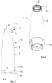
- the aerosol container 1 shown has an internal pressure-resistant plastic container 2, in particular a plastic aerosol container, with a convexly outwardly projecting dome-shaped container base 3, as is particularly shown in Fig.2 can be seen, and a stand sleeve 10.
- the plastic aerosol container 2 can be an injection molded part or produced in a blow molding process, for example in a stretch blow molding process or in an extrusion blow molding process.
- the plastic aerosol container can be single-layered or multi-layered and consist of at least 80% w/w of a main plastic component from the group consisting of polyethylene terephthalate, polyethylene naphthalate, polyethylene furanoate, polylactide, their copolymers and mixtures of the plastics mentioned. Up to 20 percent by weight (% w/w) of foreign substances can be mixed into the main plastic component. For example, copolymers, dyes, UV blockers, stabilizing additives such as glass fibers or glass beads or mixtures thereof, additives or foreign polymers can be mixed into the main plastic component.
- the main plastic component can also contain other plastics from the group consisting of PEN, PEF, PLA, polyester, polyamide, polybutylene terephthalate, polycarbonate, polyolefins, silicones, their copolymers and mixtures of the aforementioned plastics.
- the plastic aerosol container 2 has a container neck 4 with an opening 5.
- the container neck 4 has a collar 41 bordering the opening 5 with an annular groove 42 arranged below the collar 41.
- the collar 41 with the annular groove 42 can have a Facilitate assembly of a dispensing device (not shown), for example a valve unit, for an aerosol stored under pressure in the plastic aerosol container 2.
- the plastic aerosol container 2 is mounted with its area close to the ground in the stand sleeve 10, which, as particularly in Fig.2 can be seen, has a base part 11 and a jacket 12 formed in one piece therewith.
- the standing sleeve 10 is connected in a force-fitting manner to an outer wall 6 of the plastic aerosol container 2 in a region of the plastic aerosol container 2 near the base, at least with its end region 13 facing away from the base part 11.
- the standing sleeve 10 can be formed in one or more layers and is produced from an oriented polymer composition in a stretch blow molding process.
- the polymer composition for the production of the stand cuff comprises polymers whose main component, i.e.
- polystyrene polymers in particular styrene-acrylonitrile (SAN), general purpose polystyrene (GPS) high impact polystyrene (HIPS), their copolymers and mixtures of the polymers mentioned.
- PP polypropylene
- HDPE high density polyethylene
- LDPE low density polyethylene
- PET polyethylene terephthalate
- PET polyethylene furanoate
- PPF polypropylene furanoate
- PAF polylactide
- styrene polymers in particular styrene-acrylonitrile (SAN), general purpose polystyrene (GPS) high impact polystyrene (HIPS), their copolymers and mixtures of the polymers mentioned.
- GPS general purpose polystyrene
- HIPS high impact polystyrene
- the plastic aerosol container 2 and/or the stand sleeve 10 can be transparent, translucent or opaque. They can have the same or different colors.
- the stand sleeve 10 and/or the plastic aerosol container 2 can also be transparent only in some areas.
- FIG.3 shows the area of the plastic aerosol container 2 near the bottom, which is accommodated in the stand sleeve 10, on an enlarged scale.
- the bottom part of the stand sleeve 10 is again provided with the reference number 11; the jacket again bears the reference number 12.
- the end region 13 of the jacket 12 facing away from the bottom part 11 is connected in a force-fitting manner to the outer wall 6 of the plastic aerosol container 2.
- Fig.3 further shows that the base part 11 of the standing sleeve 10 has a support area 15 which extends inwards from a standing surface 14 of the base part 11 in an S-shape in the direction of the axial extension of the jacket 12.
- the support surface 16 limits the insertion path and can therefore limit the size of the frictional connection.
- the support surface 16 is arranged concentrically around a central axis II of the stand sleeve 10 and can consist of several sub-areas.
- the support surface 16 is followed by a recess 18 which is recessed compared to a contour of the container base 3 so that in the assembled state the container base 3, or the outer wall 6, only rests on the support surface 16.
- the trough 18 can have a recess 19 in order to again reduce the trough 18 precisely in the center of the container base 3, which can have an injection point that protrudes from a contour of the container base 3.
- the outer wall 6 of the dome-shaped container base 3 and the concentric convex support surface 16 in the support area 15 of the stand sleeve 10 can have essentially the same curvature. This allows the container base 3 to be supported as evenly as possible.
- the base part can also have an opening arranged approximately in the middle. This opening can be used to allow liquid or foreign bodies that get into the stand sleeve to escape from it again.
- liquid from the plastic aerosol container can run down the outer wall and get into the stand sleeve.
- the recess can allow the liquid to drain away.
- the stand sleeve is usually free of openings and/or holes.
- the container base 3 supported in the support sleeve 10 has, at its most projecting region, a distance a from a flat support surface G which is 1.5 mm to 5 mm, preferably 1.8 mm to 2.6 mm.
- the casing 12 of the standing sleeve 10 can have a substantially cylindrical axial extension at its end region 13 facing away from the base part 11.
- the casing 12 can have the shape of a bowl or a conical section, each with a decreasing outer diameter.
- the casing of the standing sleeve can be cylindrical from the end region to the base part also have a continuous cylindrical shape with a constant outer diameter.
- Fig.4 shows a perspective view of the stand cuff 10 according to Fig.3 with a view of its interior.
- the bowl-like casing bears the reference number 12.
- the base part is in turn provided with the reference number 11.
- the support area 15 with the concave support surface 16 protrudes from the base part 11 into the interior of the standing sleeve 10.
- the casing 12 of the standing sleeve 10 has a predetermined number, in the present embodiment four, expansion folds 17, which extend essentially in an axial direction and are arranged at the same angular distance from one another. Due to the expansion folds 17, the casing 12 of the standing sleeve 10 can adapt very well to the external dimensions of the plastic aerosol container in the assembly area during assembly.
- the expansion folds 17 also allow the casing 12 of the stand sleeve 10 to follow any expansion of the plastic aerosol container as a result of the internal pressure in order to prevent excessive pressure on the outer wall of the plastic container in the assembly area.
- the expansion folds can be designed in such a way that they are practically invisible when expanded.
- the expansion folds extend over the entire height of the casing 12.
- the expansion folds 17 extend only over the height at which the container base is clamped in a force-fitting manner.
- FIG. 5 an intermediate container 20, which is produced in a stretch blow molding process from a preform usually produced in an injection molding process. Preforms that are relatively short in relation to their diameter can be used in particular. For example, such preforms have a total length of 15 mm to 150 mm.
- the production of the stand sleeve 10 takes place in particular in a so-called "lost neck process". In this process, an excess part of the intermediate container 20, which is also referred to as the dome 21, is separated off with a cutting or punching tool 22, as shown in Figure 6 The separated dome 21 can be recycled. The remaining section of the intermediate container forms the stand sleeve 10.
- the production of the stand sleeve 10 offers the possibility of calibrating the sections of the casing 12 that are essential for the assembly of the standing cuff 10, in particular the end section 13 of the casing 12 facing away from the base part 11, in order to ensure the dimensional accuracy required for assembly.
- the cut can also be made at a predetermined angle to the central axis, so that the end region 13 of the casing 12 has an insertion bevel that makes it easier to insert the plastic aerosol container into the cuff 10.
Landscapes
- Engineering & Computer Science (AREA)
- Mechanical Engineering (AREA)
- Manufacturing & Machinery (AREA)
- Chemical & Material Sciences (AREA)
- Dispersion Chemistry (AREA)
- General Engineering & Computer Science (AREA)
- Containers And Packaging Bodies Having A Special Means To Remove Contents (AREA)
- Nozzles (AREA)
Claims (14)
- Manchon d'appui (10) destiné à un récipient en matière plastique (2) résistant à la pression interne, notamment à un récipient aérosol en matière plastique, manchon qui présente une partie de fond (11), dotée d'une surface d'appui (14), et une enveloppe (12) fermée dans la direction périphérique, sachant que la partie de fond (11) et l'enveloppe (12) sont réalisées d'une seule pièce l'une avec l'autre, et que l'enveloppe (12) est conçue pour une liaison par adhérence, sachant que la partie de fond (11) et l'enveloppe (12) sont réalisées selon un procédé d'étirage-soufflage et que l'enveloppe (12) est réalisée à proximité du fond d'un récipient en matière plastique (2) résistant à la pression interne, en vue de la liaison par adhérence avec une paroi externe (6), caractérisé en ce que l'enveloppe (12) présente au moins un pli d'expansion (17) qui s'étend sensiblement dans une direction axiale.
- Manchon d'appui (10) selon la revendication 1, caractérisé en ce qu'il est fabriqué selon un procédé à col perdu.
- Manchon d'appui (10) selon la revendication 1, caractérisé en ce que l'enveloppe (12) présente deux ou plusieurs plis d'expansion (17) qui sont disposés à égales distances angulaires les uns des autres.
- Manchon d'appui (10) selon l'une des revendications précédentes, caractérisé en ce que la partie de fond (11) présente une zone de support (15) qui s'étend vers l'intérieur depuis la surface d'appui (14) et présente au moins une surface de support (16) disposée de manière concentrique et destinée à soutenir un fond de récipient, à l'état assemblé.
- Manchon d'appui (10) selon l'une des revendications précédentes, caractérisé en ce que la partie de fond (11) présente un renfoncement (19) disposé à peu près au centre.
- Manchon d'appui (10) selon l'une des revendications précédentes, caractérisé en ce qu'il est constitué d'un composé polymère orienté.
- Manchon d'appui (10) selon la revendication 6, caractérisé en ce qu'il est constitué de polymères dont le constituant principal, à savoir plus de 70 pour cent en poids, est formé d'au moins un matériau appartenant au groupe comprenant des polyoléfines, notamment du polypropylène (PP), High Density Olyethylen (HDPE), Low Density Polyethylen (LDPE), des polyesters, notamment du polyéthylène téréphtalate (PET), polyéthylène furanoate (PEF), polypropylène furanoate (PPF), des polylactides (PLA), des polymères styréniques, notamment styrène-acrylonitrile (SAN), General Purpose Polystyrene (GPS), High Impact Polystyrene (HIPS), leurs copolymères et des mélanges des polymères cités.
- Manchon d'appui (10) selon l'une des revendications précédentes, caractérisé en ce qu'il est réalisé de manière transparente au moins par portions.
- Emballage aérosol comprenant un récipient en matière plastique (2) résistant à la pression interne, notamment un récipient aérosol en matière plastique, doté d'un fond de récipient (3) en forme de dôme faisant saillie de manière convexe vers l'extérieur, et un manchon d'appui (10) selon l'une des revendications précédentes, caractérisé en ce que, à proximité du fond du récipient en matière plastique (2), le manchon d'appui (10) est relié par adhérence à une paroi externe (6) du récipient en matière plastique (2).
- Emballage aérosol selon la revendication 9, caractérisé en ce que l'enveloppe (12) du manchon d'appui (10) présente, au moins dans une partie d'extrémité (13) opposée à la partie de fond (11), un diamètre intérieur qui est plus petit qu'un diamètre extérieur du récipient aérosol en matière plastique (2), dans une région proche du fond qui est prévue pour la liaison par adhérence.
- Emballage aérosol selon la revendication 10, caractérisé en ce que le diamètre intérieur de la partie d'extrémité (13) du manchon d'appui (10) est inférieur de 0,2 mm à 6 mm au diamètre extérieur de l'emballage aérosol en matière plastique (2), dans la région proche du fond, à l'état sans pression et à 20 °C.
- Emballage aérosol selon l'une des revendications 9 à 11, comprenant un manchon d'appui selon la revendication 4, caractérisé en ce que, dans la région du fond de récipient (3) en forme de dôme, la paroi externe (6) est soutenue par la surface de support (16).
- Emballage aérosol selon la revendication 12, caractérisé en ce que la paroi extérieure (6), soutenue par la surface de support (16), et la surface de support (16) présentent sensiblement la même courbure.
- Emballage aérosol selon la revendication 12 ou 13, caractérisé en ce que, dans sa partie la plus proéminente, le fond de récipient (3) soutenu présente une distance (a) par rapport à une surface de pose (G) plane, qui est d'environ 1,5 mm à environ 5 mm, de préférence d'environ 1,8 mm à environ 2,6 mm.
Applications Claiming Priority (2)
| Application Number | Priority Date | Filing Date | Title |
|---|---|---|---|
| CH00382/17A CH713614A1 (de) | 2017-03-23 | 2017-03-23 | Standmanschette für einen innendruckbeständigen Kunststoffbehälter, insbesondere für einen Kunststoff-Aerosolbehälter, und mit einer Standmanschette ausgestattetes Aerosolgebinde. |
| PCT/EP2018/055389 WO2018172052A1 (fr) | 2017-03-23 | 2018-03-06 | Manchon d'appui au sol pour un contenant en matière plastique résistant à la pression intérieure |
Publications (3)
| Publication Number | Publication Date |
|---|---|
| EP3601078A1 EP3601078A1 (fr) | 2020-02-05 |
| EP3601078C0 EP3601078C0 (fr) | 2024-05-01 |
| EP3601078B1 true EP3601078B1 (fr) | 2024-05-01 |
Family
ID=58412822
Family Applications (1)
| Application Number | Title | Priority Date | Filing Date |
|---|---|---|---|
| EP18709536.9A Active EP3601078B1 (fr) | 2017-03-23 | 2018-03-06 | Manchon d'appui au sol pour un contenant en matière plastique résistant à la pression intérieure |
Country Status (8)
| Country | Link |
|---|---|
| US (1) | US11046481B2 (fr) |
| EP (1) | EP3601078B1 (fr) |
| CN (1) | CN110475724B (fr) |
| BR (1) | BR112019018769B1 (fr) |
| CH (1) | CH713614A1 (fr) |
| MX (2) | MX2019010365A (fr) |
| RU (1) | RU2753038C2 (fr) |
| WO (1) | WO2018172052A1 (fr) |
Families Citing this family (3)
| Publication number | Priority date | Publication date | Assignee | Title |
|---|---|---|---|---|
| SE544653C2 (en) * | 2020-07-08 | 2022-10-04 | Aarke Ab | Beverage bottle and method for joining thereof |
| US11628966B2 (en) * | 2021-04-12 | 2023-04-18 | Dart Industries Inc. | Freezable and reusable bottle and method of making the bottle |
| CA3155296A1 (fr) * | 2022-04-13 | 2023-10-13 | Ditech Manufacturing Ltd. | Housse de protection a pattes pour un reservoir cylindrique |
Citations (3)
| Publication number | Priority date | Publication date | Assignee | Title |
|---|---|---|---|---|
| US4367820A (en) * | 1980-03-03 | 1983-01-11 | Yoshino Kogyosho Co., Ltd. | Saturated polyester resin bottle and stand |
| JPH05246435A (ja) * | 1991-09-03 | 1993-09-24 | Dainippon Printing Co Ltd | 耐熱耐圧ボトル |
| EP1126433A1 (fr) * | 2000-02-16 | 2001-08-22 | Bernard Labatut | Dispositif de présentation d'informations pour des bouteilles |
Family Cites Families (34)
| Publication number | Priority date | Publication date | Assignee | Title |
|---|---|---|---|---|
| US937850A (en) * | 1909-08-19 | 1909-10-26 | James W Davis | Coaster and bottle-opener. |
| US3229949A (en) * | 1964-07-16 | 1966-01-18 | Peter G Chaconas | Dewar flask holder |
| US3666163A (en) * | 1969-03-20 | 1972-05-30 | Sobrefina Sa | Packaging container |
| US3726429A (en) * | 1970-12-28 | 1973-04-10 | Monsanto Co | Package for holding pressurized fluent materials |
| US4082200A (en) * | 1976-06-29 | 1978-04-04 | Owens-Illinois, Inc. | Plastic container with support base, and method of assembly |
| SE430148B (sv) * | 1979-05-11 | 1983-10-24 | Plm Ab | Behallare bestaende av en behallarkropp av plastmaterial med en konvex bottendel och av en stasockel for uppstodjande av behallarkroppen |
| US4436216A (en) * | 1982-08-30 | 1984-03-13 | Owens-Illinois, Inc. | Ribbed base cups |
| US4609418A (en) * | 1983-05-16 | 1986-09-02 | Yoshino Kogyosho Co., Ltd. | Hollow container of biaxially oriented synthetic resin engaged with base cap on bottom and method of engaging the cap with the container |
| US4961701A (en) * | 1986-11-24 | 1990-10-09 | Hoover Universal, Inc. | Apparatus for forming plastic bottle base cups |
| JPH0734828Y2 (ja) * | 1989-03-09 | 1995-08-09 | 株式会社吉野工業所 | 合成樹脂製壜体 |
| US4955493A (en) * | 1989-08-15 | 1990-09-11 | Touzani William N | Collapsible expansible plastic hollow articles in a latchable configuration |
| US5427258A (en) * | 1992-04-09 | 1995-06-27 | Continental Pet Technologies, Inc. | Freestanding container with improved combination of properties |
| EP0612667A3 (fr) * | 1993-02-23 | 1995-02-08 | Gen Electric | Pièce inférieure en forme d'écuelle pour bouteilles en plastique à base hémisphérique. |
| CN2368794Y (zh) * | 1998-10-19 | 2000-03-15 | 烟台烟港实业有限公司 | 一种带有发声发光装置的瓶子底座 |
| US20020027173A1 (en) | 1999-03-23 | 2002-03-07 | Polifka Francis D. | Apparatus and method for circular vortex air flow material grinding |
| JP4769791B2 (ja) * | 2004-03-11 | 2011-09-07 | グラハム パッケージング カンパニー,エル ピー | プラスチック容器運搬方法 |
| US20060060554A1 (en) * | 2004-09-20 | 2006-03-23 | Garman Thomas B | Blow molded plastic aerosol container |
| ITSV20050033A1 (it) * | 2005-10-11 | 2007-04-12 | Ribi Pack S P A | Tappo antieffrazione per sigillare bottiglie mediante una membrana in polimero plastico estensibile predisposta su di un'armatura cava alloggiata in un cappuccio rigido preformato |
| FR2921642B1 (fr) * | 2007-09-28 | 2011-07-15 | Power Container Corp | Dispositif de distribution de produit fluide, procede de realisation d'un tel dispositif et appareil pour la mise en oeuvre d'un tel procede |
| US8439223B2 (en) | 2007-08-20 | 2013-05-14 | The Procter & Gamble Company | Base cup for a supportable pressurizable container |
| US20090050599A1 (en) * | 2007-08-20 | 2009-02-26 | Matthew John Martin | Supportable pressurizable container having a bottom for receiving a dip tube and base cup therefor |
| CN201604857U (zh) * | 2010-01-25 | 2010-10-13 | 梁木鸿 | 带有底座的塑料瓶子 |
| TWM406023U (en) * | 2010-11-26 | 2011-06-21 | An-Zong Cai | Non-residual cone-type bottom container |
| WO2012102619A2 (fr) | 2011-01-24 | 2012-08-02 | Agroplas Asa | Dispositif et procédé de traitement de matériaux |
| CN102814221B (zh) | 2011-06-09 | 2014-10-29 | 稷富国际科技有限公司 | 超音速撞击粉碎装置 |
| CH707062A1 (de) * | 2012-10-04 | 2014-04-15 | Alpla Werke | Supportringloser Kunststoffbehälter, insbesondere Kunststoffflasche. |
| CN203494602U (zh) | 2013-09-17 | 2014-03-26 | 青岛世纳机械设备有限公司 | 多转子大型超细气流粉碎分级一体机 |
| US9724703B2 (en) | 2014-06-06 | 2017-08-08 | LLT International (Ireland) Ltd. | Systems and methods for processing solid materials using shockwaves produced in a supersonic gaseous vortex |
| DE102014113915A1 (de) * | 2014-09-25 | 2016-03-31 | Krones Aktiengesellschaft | Komprimierbares Kunststoffbehältnis mit Bodentasse |
| DK3250475T3 (da) * | 2015-01-27 | 2019-12-09 | Airopack Tech Group B V | Trykstyresystem |
| CA2974454C (fr) * | 2015-01-28 | 2020-04-14 | Airopack Technology Group B.V. | Systeme de regulation de pression |
| CN204674981U (zh) * | 2015-05-26 | 2015-09-30 | 高满珍 | 制冷式改良酒瓶 |
| GB2552712A (en) * | 2016-08-05 | 2018-02-07 | Pet Eng & Services S R L | Containers with adhesively attached chimes |
| CN106076562B (zh) | 2016-08-16 | 2018-09-18 | 浙江国正安全技术有限公司 | 流化床气流粉碎机 |
-
2017
- 2017-03-23 CH CH00382/17A patent/CH713614A1/de not_active Application Discontinuation
-
2018
- 2018-03-06 WO PCT/EP2018/055389 patent/WO2018172052A1/fr not_active Ceased
- 2018-03-06 BR BR112019018769-3A patent/BR112019018769B1/pt not_active IP Right Cessation
- 2018-03-06 RU RU2019133465A patent/RU2753038C2/ru active
- 2018-03-06 MX MX2019010365A patent/MX2019010365A/es unknown
- 2018-03-06 EP EP18709536.9A patent/EP3601078B1/fr active Active
- 2018-03-06 CN CN201880020283.2A patent/CN110475724B/zh not_active Expired - Fee Related
-
2019
- 2019-08-30 MX MX2024002858A patent/MX2024002858A/es unknown
- 2019-09-18 US US16/574,329 patent/US11046481B2/en active Active
Patent Citations (3)
| Publication number | Priority date | Publication date | Assignee | Title |
|---|---|---|---|---|
| US4367820A (en) * | 1980-03-03 | 1983-01-11 | Yoshino Kogyosho Co., Ltd. | Saturated polyester resin bottle and stand |
| JPH05246435A (ja) * | 1991-09-03 | 1993-09-24 | Dainippon Printing Co Ltd | 耐熱耐圧ボトル |
| EP1126433A1 (fr) * | 2000-02-16 | 2001-08-22 | Bernard Labatut | Dispositif de présentation d'informations pour des bouteilles |
Also Published As
| Publication number | Publication date |
|---|---|
| BR112019018769B1 (pt) | 2023-02-28 |
| CH713614A1 (de) | 2018-09-28 |
| RU2019133465A3 (fr) | 2021-06-25 |
| RU2753038C2 (ru) | 2021-08-11 |
| EP3601078C0 (fr) | 2024-05-01 |
| US11046481B2 (en) | 2021-06-29 |
| CN110475724A (zh) | 2019-11-19 |
| MX2019010365A (es) | 2019-12-02 |
| US20200010241A1 (en) | 2020-01-09 |
| RU2019133465A (ru) | 2021-04-23 |
| MX2024002858A (es) | 2024-03-21 |
| CN110475724B (zh) | 2022-04-08 |
| BR112019018769A2 (pt) | 2020-04-07 |
| WO2018172052A1 (fr) | 2018-09-27 |
| EP3601078A1 (fr) | 2020-02-05 |
Similar Documents
| Publication | Publication Date | Title |
|---|---|---|
| EP2585264B1 (fr) | Préforme pour réaliser des récipients en matière plastique dans le cadre d'un processus d'étirage-soufflage et procédé pour réaliser la préforme | |
| EP2064039B1 (fr) | Ébauche et procédé de fabrication de bouteilles en plastique | |
| EP3509809B1 (fr) | Réservoir aérosol en matière plastique | |
| DE60104849T2 (de) | Schnappkragen für glassbehälter | |
| EP2709918B1 (fr) | Récipient en plastique à col coupé fabriqué par un procédé de formage par soufflage-étirage | |
| EP2675714B1 (fr) | Récipient en matière plastique muni d'un bec verseur | |
| DE69825632T2 (de) | Blasgeformter freistehender behälter aus kunststoff | |
| EP3601078B1 (fr) | Manchon d'appui au sol pour un contenant en matière plastique résistant à la pression intérieure | |
| DE320151T1 (de) | Streckblasformung eines weithalsbehaelters und eines zwischenprodukts aus pet. | |
| DE2551244A1 (de) | Kombinationsanordnung aus einer thermoplastischen flasche und einem haltenapf | |
| EP2802235B1 (fr) | Contenant en plastique pour un déodorant à bille | |
| DE19647260A1 (de) | Behältnis und Verfahren zu seiner Herstellung | |
| EP3187430B1 (fr) | Récipient en plastique sans bague de support, en particulier bouteille en plastique | |
| DE2915228A1 (de) | Verpackungsbehaelter fuer fluessige und rieselfaehige produkte und verfahren zum herstellen des behaelters | |
| EP1497189B1 (fr) | Bouteille en plastique | |
| WO2016066398A1 (fr) | Récipient en matière plastique avec bouche de récipient scellable | |
| DE19917916B4 (de) | Verfahren zur Herstellung einer Kunststoffflasche und damit herstellbare Flasche | |
| EP3359363B1 (fr) | Préforme pour la fabrication d'un récipient en matériau synthétique dans un procédé d'étirage-soufflage | |
| DE69014589T2 (de) | Flasche aus kunststoffharz. | |
| CH715582A1 (de) | Kunststoffbehälter mit wenigstens bereichsweise scharfkantig ausgebildeter Behältergeometrie und Verfahren zur Herstellung des Kunststoffbehälters. | |
| EP3826822B1 (fr) | Procédé d'étirage-soufflage pour la fabrication d'un récipient en matériau synthétique et récipient en matériau synthétique fabriqué dans un procédé d'étirage-soufflage | |
| CH707260A1 (de) | Extrusionsgeblasener Kunststoffbehälter mit wenigstens einer kalibrierten Strukturierung an einer Innenwand eines Behälterhalses und Verfahren zu dessen Herstellung. | |
| DE102012107262A1 (de) | Kunststoffbehältnis mit Saugelement | |
| EP1293328A1 (fr) | Pieces moulées par injection, notamment de préformes | |
| DE202012013615U1 (de) | Vorformling zum Herstellen eines Behältnisses und Behältnis zum Aufnehmen eines Lebensmittels |
Legal Events
| Date | Code | Title | Description |
|---|---|---|---|
| STAA | Information on the status of an ep patent application or granted ep patent |
Free format text: STATUS: UNKNOWN |
|
| STAA | Information on the status of an ep patent application or granted ep patent |
Free format text: STATUS: THE INTERNATIONAL PUBLICATION HAS BEEN MADE |
|
| PUAI | Public reference made under article 153(3) epc to a published international application that has entered the european phase |
Free format text: ORIGINAL CODE: 0009012 |
|
| STAA | Information on the status of an ep patent application or granted ep patent |
Free format text: STATUS: REQUEST FOR EXAMINATION WAS MADE |
|
| 17P | Request for examination filed |
Effective date: 20190904 |
|
| AK | Designated contracting states |
Kind code of ref document: A1 Designated state(s): AL AT BE BG CH CY CZ DE DK EE ES FI FR GB GR HR HU IE IS IT LI LT LU LV MC MK MT NL NO PL PT RO RS SE SI SK SM TR |
|
| AX | Request for extension of the european patent |
Extension state: BA ME |
|
| DAV | Request for validation of the european patent (deleted) | ||
| DAX | Request for extension of the european patent (deleted) | ||
| STAA | Information on the status of an ep patent application or granted ep patent |
Free format text: STATUS: EXAMINATION IS IN PROGRESS |
|
| 17Q | First examination report despatched |
Effective date: 20210317 |
|
| GRAP | Despatch of communication of intention to grant a patent |
Free format text: ORIGINAL CODE: EPIDOSNIGR1 |
|
| STAA | Information on the status of an ep patent application or granted ep patent |
Free format text: STATUS: GRANT OF PATENT IS INTENDED |
|
| RIC1 | Information provided on ipc code assigned before grant |
Ipc: B29C 49/08 20060101ALI20231108BHEP Ipc: B65D 23/00 20060101AFI20231108BHEP |
|
| INTG | Intention to grant announced |
Effective date: 20231205 |
|
| GRAS | Grant fee paid |
Free format text: ORIGINAL CODE: EPIDOSNIGR3 |
|
| GRAA | (expected) grant |
Free format text: ORIGINAL CODE: 0009210 |
|
| STAA | Information on the status of an ep patent application or granted ep patent |
Free format text: STATUS: THE PATENT HAS BEEN GRANTED |
|
| AK | Designated contracting states |
Kind code of ref document: B1 Designated state(s): AL AT BE BG CH CY CZ DE DK EE ES FI FR GB GR HR HU IE IS IT LI LT LU LV MC MK MT NL NO PL PT RO RS SE SI SK SM TR |
|
| RAP3 | Party data changed (applicant data changed or rights of an application transferred) |
Owner name: ALPLA WERKE ALWIN LEHNER GMBH & CO. KG |
|
| REG | Reference to a national code |
Ref country code: GB Ref legal event code: FG4D Free format text: NOT ENGLISH |
|
| REG | Reference to a national code |
Ref country code: CH Ref legal event code: EP |
|
| REG | Reference to a national code |
Ref country code: DE Ref legal event code: R096 Ref document number: 502018014528 Country of ref document: DE |
|
| REG | Reference to a national code |
Ref country code: IE Ref legal event code: FG4D Free format text: LANGUAGE OF EP DOCUMENT: GERMAN |
|
| U01 | Request for unitary effect filed |
Effective date: 20240501 |
|
| U07 | Unitary effect registered |
Designated state(s): AT BE BG DE DK EE FI FR IT LT LU LV MT NL PT SE SI Effective date: 20240507 |
|
| PG25 | Lapsed in a contracting state [announced via postgrant information from national office to epo] |
Ref country code: IS Free format text: LAPSE BECAUSE OF FAILURE TO SUBMIT A TRANSLATION OF THE DESCRIPTION OR TO PAY THE FEE WITHIN THE PRESCRIBED TIME-LIMIT Effective date: 20240901 |
|
| PG25 | Lapsed in a contracting state [announced via postgrant information from national office to epo] |
Ref country code: HR Free format text: LAPSE BECAUSE OF FAILURE TO SUBMIT A TRANSLATION OF THE DESCRIPTION OR TO PAY THE FEE WITHIN THE PRESCRIBED TIME-LIMIT Effective date: 20240501 |
|
| PG25 | Lapsed in a contracting state [announced via postgrant information from national office to epo] |
Ref country code: GR Free format text: LAPSE BECAUSE OF FAILURE TO SUBMIT A TRANSLATION OF THE DESCRIPTION OR TO PAY THE FEE WITHIN THE PRESCRIBED TIME-LIMIT Effective date: 20240802 |
|
| PG25 | Lapsed in a contracting state [announced via postgrant information from national office to epo] |
Ref country code: ES Free format text: LAPSE BECAUSE OF FAILURE TO SUBMIT A TRANSLATION OF THE DESCRIPTION OR TO PAY THE FEE WITHIN THE PRESCRIBED TIME-LIMIT Effective date: 20240501 |
|
| PG25 | Lapsed in a contracting state [announced via postgrant information from national office to epo] |
Ref country code: PL Free format text: LAPSE BECAUSE OF FAILURE TO SUBMIT A TRANSLATION OF THE DESCRIPTION OR TO PAY THE FEE WITHIN THE PRESCRIBED TIME-LIMIT Effective date: 20240501 |
|
| PG25 | Lapsed in a contracting state [announced via postgrant information from national office to epo] |
Ref country code: PL Free format text: LAPSE BECAUSE OF FAILURE TO SUBMIT A TRANSLATION OF THE DESCRIPTION OR TO PAY THE FEE WITHIN THE PRESCRIBED TIME-LIMIT Effective date: 20240501 Ref country code: NO Free format text: LAPSE BECAUSE OF FAILURE TO SUBMIT A TRANSLATION OF THE DESCRIPTION OR TO PAY THE FEE WITHIN THE PRESCRIBED TIME-LIMIT Effective date: 20240801 Ref country code: IS Free format text: LAPSE BECAUSE OF FAILURE TO SUBMIT A TRANSLATION OF THE DESCRIPTION OR TO PAY THE FEE WITHIN THE PRESCRIBED TIME-LIMIT Effective date: 20240901 Ref country code: HR Free format text: LAPSE BECAUSE OF FAILURE TO SUBMIT A TRANSLATION OF THE DESCRIPTION OR TO PAY THE FEE WITHIN THE PRESCRIBED TIME-LIMIT Effective date: 20240501 Ref country code: GR Free format text: LAPSE BECAUSE OF FAILURE TO SUBMIT A TRANSLATION OF THE DESCRIPTION OR TO PAY THE FEE WITHIN THE PRESCRIBED TIME-LIMIT Effective date: 20240802 Ref country code: ES Free format text: LAPSE BECAUSE OF FAILURE TO SUBMIT A TRANSLATION OF THE DESCRIPTION OR TO PAY THE FEE WITHIN THE PRESCRIBED TIME-LIMIT Effective date: 20240501 Ref country code: RS Free format text: LAPSE BECAUSE OF FAILURE TO SUBMIT A TRANSLATION OF THE DESCRIPTION OR TO PAY THE FEE WITHIN THE PRESCRIBED TIME-LIMIT Effective date: 20240801 |
|
| PG25 | Lapsed in a contracting state [announced via postgrant information from national office to epo] |
Ref country code: CZ Free format text: LAPSE BECAUSE OF FAILURE TO SUBMIT A TRANSLATION OF THE DESCRIPTION OR TO PAY THE FEE WITHIN THE PRESCRIBED TIME-LIMIT Effective date: 20240501 |
|
| PG25 | Lapsed in a contracting state [announced via postgrant information from national office to epo] |
Ref country code: RO Free format text: LAPSE BECAUSE OF FAILURE TO SUBMIT A TRANSLATION OF THE DESCRIPTION OR TO PAY THE FEE WITHIN THE PRESCRIBED TIME-LIMIT Effective date: 20240501 Ref country code: SK Free format text: LAPSE BECAUSE OF FAILURE TO SUBMIT A TRANSLATION OF THE DESCRIPTION OR TO PAY THE FEE WITHIN THE PRESCRIBED TIME-LIMIT Effective date: 20240501 |
|
| PG25 | Lapsed in a contracting state [announced via postgrant information from national office to epo] |
Ref country code: SM Free format text: LAPSE BECAUSE OF FAILURE TO SUBMIT A TRANSLATION OF THE DESCRIPTION OR TO PAY THE FEE WITHIN THE PRESCRIBED TIME-LIMIT Effective date: 20240501 |
|
| PG25 | Lapsed in a contracting state [announced via postgrant information from national office to epo] |
Ref country code: SM Free format text: LAPSE BECAUSE OF FAILURE TO SUBMIT A TRANSLATION OF THE DESCRIPTION OR TO PAY THE FEE WITHIN THE PRESCRIBED TIME-LIMIT Effective date: 20240501 Ref country code: SK Free format text: LAPSE BECAUSE OF FAILURE TO SUBMIT A TRANSLATION OF THE DESCRIPTION OR TO PAY THE FEE WITHIN THE PRESCRIBED TIME-LIMIT Effective date: 20240501 Ref country code: RO Free format text: LAPSE BECAUSE OF FAILURE TO SUBMIT A TRANSLATION OF THE DESCRIPTION OR TO PAY THE FEE WITHIN THE PRESCRIBED TIME-LIMIT Effective date: 20240501 Ref country code: CZ Free format text: LAPSE BECAUSE OF FAILURE TO SUBMIT A TRANSLATION OF THE DESCRIPTION OR TO PAY THE FEE WITHIN THE PRESCRIBED TIME-LIMIT Effective date: 20240501 |
|
| REG | Reference to a national code |
Ref country code: DE Ref legal event code: R097 Ref document number: 502018014528 Country of ref document: DE |
|
| PLBE | No opposition filed within time limit |
Free format text: ORIGINAL CODE: 0009261 |
|
| STAA | Information on the status of an ep patent application or granted ep patent |
Free format text: STATUS: NO OPPOSITION FILED WITHIN TIME LIMIT |
|
| 26N | No opposition filed |
Effective date: 20250204 |
|
| U20 | Renewal fee for the european patent with unitary effect paid |
Year of fee payment: 8 Effective date: 20250325 |
|
| PG25 | Lapsed in a contracting state [announced via postgrant information from national office to epo] |
Ref country code: MC Free format text: LAPSE BECAUSE OF FAILURE TO SUBMIT A TRANSLATION OF THE DESCRIPTION OR TO PAY THE FEE WITHIN THE PRESCRIBED TIME-LIMIT Effective date: 20240501 |
|
| REG | Reference to a national code |
Ref country code: CH Ref legal event code: H13 Free format text: ST27 STATUS EVENT CODE: U-0-0-H10-H13 (AS PROVIDED BY THE NATIONAL OFFICE) Effective date: 20251023 |
|
| PG25 | Lapsed in a contracting state [announced via postgrant information from national office to epo] |
Ref country code: CH Free format text: LAPSE BECAUSE OF NON-PAYMENT OF DUE FEES Effective date: 20250331 |
|
| PG25 | Lapsed in a contracting state [announced via postgrant information from national office to epo] |
Ref country code: IE Free format text: LAPSE BECAUSE OF NON-PAYMENT OF DUE FEES Effective date: 20250306 |
|
| PGFP | Annual fee paid to national office [announced via postgrant information from national office to epo] |
Ref country code: GB Payment date: 20260324 Year of fee payment: 9 |