EP3606806B1 - Heckspoilereinrichtung für ein nutzfahrzeug - Google Patents
Heckspoilereinrichtung für ein nutzfahrzeug Download PDFInfo
- Publication number
- EP3606806B1 EP3606806B1 EP18715536.1A EP18715536A EP3606806B1 EP 3606806 B1 EP3606806 B1 EP 3606806B1 EP 18715536 A EP18715536 A EP 18715536A EP 3606806 B1 EP3606806 B1 EP 3606806B1
- Authority
- EP
- European Patent Office
- Prior art keywords
- roof air
- guiding element
- rear spoiler
- roof
- coupling device
- Prior art date
- Legal status (The legal status is an assumption and is not a legal conclusion. Google has not performed a legal analysis and makes no representation as to the accuracy of the status listed.)
- Active
Links
Images

Classifications
-
- B—PERFORMING OPERATIONS; TRANSPORTING
- B62—LAND VEHICLES FOR TRAVELLING OTHERWISE THAN ON RAILS
- B62D—MOTOR VEHICLES; TRAILERS
- B62D35/00—Vehicle bodies characterised by streamlining
- B62D35/001—For commercial vehicles or tractor-trailer combinations, e.g. caravans
-
- B—PERFORMING OPERATIONS; TRANSPORTING
- B62—LAND VEHICLES FOR TRAVELLING OTHERWISE THAN ON RAILS
- B62D—MOTOR VEHICLES; TRAILERS
- B62D35/00—Vehicle bodies characterised by streamlining
- B62D35/007—Rear spoilers
-
- Y—GENERAL TAGGING OF NEW TECHNOLOGICAL DEVELOPMENTS; GENERAL TAGGING OF CROSS-SECTIONAL TECHNOLOGIES SPANNING OVER SEVERAL SECTIONS OF THE IPC; TECHNICAL SUBJECTS COVERED BY FORMER USPC CROSS-REFERENCE ART COLLECTIONS [XRACs] AND DIGESTS
- Y02—TECHNOLOGIES OR APPLICATIONS FOR MITIGATION OR ADAPTATION AGAINST CLIMATE CHANGE
- Y02T—CLIMATE CHANGE MITIGATION TECHNOLOGIES RELATED TO TRANSPORTATION
- Y02T10/00—Road transport of goods or passengers
- Y02T10/80—Technologies aiming to reduce greenhouse gasses emissions common to all road transportation technologies
- Y02T10/82—Elements for improving aerodynamics
Definitions
- the invention relates to a rear spoiler device for a utility vehicle and a utility vehicle of this type.
- the vehicle has two rear doors that can each be swung open to the rear and to the outside, in particular from a closed position by more than 180 °, e.g. B. about 250 ° or 270 °, can be pivoted forward in order to apply them to the side walls of a box-shaped structure of the commercial vehicle and, if necessary, to lock them.
- 180 ° e.g. B. about 250 ° or 270 °
- Such rear spoiler devices are provided in particular on commercial vehicles with a blunt rear or an essentially box-shaped structure;
- the rear spoiler device with the extended roof air guiding elements enables an aerodynamic contour extension to the rear in order to at least reduce the spoiler vortex at the blunt spoiler edge.
- Such a rear spoiler device generally has roof air guiding elements which, for. B. can be attached to the rear door and are adjustable between a folded basic position in which they lie flat against the rear door, and an unfolded driving position.
- the US 2004/0119319 A1 shows a vehicle with such a rear spoiler device.
- the roof air deflectors extend the roof surface of the vehicle to the rear and can be folded inwards. In the retracted state, the rear spoiler device can pivot away with the rear doors and release the cargo space.
- FIG. 13 shows another rear spoiler device which is attached to the side walls of the vehicle and a fold in FIG Vehicle longitudinal direction enabled, such a rear spoiler device fills the entire rear surface of the vehicle.
- Adjusting the two roof air guiding elements is relatively complex, however.
- the user must generally both roof air control elements by adjusting devices such.
- B. adjust push-pull struts to adjust the rear spoiler device in the driving position.
- two adjustment devices must be provided for the two roof air control elements.
- the US 2009/200834 A1 discloses a rear spoiler device for a vehicle with an upper air guiding element, side air guiding elements and a lower air guiding element.
- the upper air guiding element, the side air guiding elements and the lower air guiding element rest against a rear of the vehicle in a state of rest.
- the upper air guiding element can be automatically pivoted into an unfolded state when an air flow flows around the vehicle.
- the upper air guiding element can pull the side air guiding elements outward, which in turn pull the lower air guiding element outward.
- the invention is therefore based on the object of creating a rear spoiler device for a utility vehicle which can be designed with relatively little effort and which enables reliable adjustment.
- the invention is based on the knowledge that the two roof air guiding elements each perform a folding movement or pivoting movement, which in principle can also be combined with one another.
- a coupling device is thus provided which enables the pivoting movement or folding movement of the roof air guiding elements to be coupled.
- the coupling device on a first roof air guide element, for. B. the left roof air guiding element is provided, and couples or takes the other, second roof air guiding element with the pivoting movement of the first roof air guiding element.
- the user only has to actively move the first roof air guiding element from the basic position to the driving position, whereby the second roof air guiding element is also pivoted due to the coupling device.
- the coupling takes place through an overlap between the roof air guiding elements, in which the actively adjusted first roof air guiding element protrudes under an inner edge of the second roof air guiding element.
- the coupling device of the first roof air guiding element protrudes under the second roof air guiding element; and a counter-coupling device, which interacts with the (first) coupling device, can also be provided on the second roof air guiding element.
- the coupling device and also the counter-coupling device can in particular also be used as plastic angles or profiles or as metal angles or profiles, e.g. B. with the shape as U-shaped or S-shaped Profiles are formed, which can thus be subsequently attached to roof air guiding elements and allow safe engagement, for. B. by angle or profile areas.
- the coupling of the roof air control elements does not affect the regular use of the rear doors.
- the user can in the usual way with the rear spoiler device retracted, i. H. Open the rear doors if the roof air control elements are resting on the rear doors.
- the user can first open the right rear door with the second roof air deflector element in the usual way, and also pivot the opened rear door outward and forward in the usual way to rest against the side wall.
- the coupling device and counter-coupling device lift from one another in the basic position without any problems, so that there is no impairment here.
- there is preferably a non-latching support so that the right rear door with the second roof air guiding element can easily lift off the first roof air guiding element.
- the user After opening the first rear door, the user can subsequently open the second rear door with the first roof air guiding element and also pivot it outward or outward and forward to rest against the side wall.
- the user only has to actuate one adjustment device for actively pivoting the first roof air guiding element from the basic position to the driving position, whereby the second roof air guiding element is taken along and is also swiveled into the driving position.
- the user resets the first roof air guide element accordingly, which generally swings downwards by itself due to the force of gravity; the second roof air deflector element can also be due to its gravity when it is no longer of the first roof air control element is worn, swivel down into the basic position.
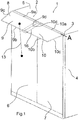
- the commercial vehicle 1 From a commercial vehicle 1 is in Fig. 1 and 2 the stern 2 shown.
- the commercial vehicle 1 here has a blunt end or a blunt rear end and is z. B. designed as a box-shaped truck.
- the commercial vehicle 1 has a vehicle structure 3, which at the rear 2 z. B. forms a portal, two side walls 4, of which the right side wall 4 in the direction of travel can be seen in the perspective views, and a roof surface 5.
- a rear spoiler device 8 is provided on the rear 2, which has a first, left roof air guiding element 9 and a second, right roof air guiding element 10.
- the roof air guiding elements 9, 10 are, for. B. made of a plastic material and can be flat or slightly curved as shown in the figures. They can be swiveled out or folded out between a basic position in which they rest against the rear doors 6, 7, and a driving position. In the in Fig. 1 , 2 They are used to aerodynamically lengthen the contour of the roof surface 5 to the rear and are slightly inclined downwards relative to the horizontal.
- side air guide elements which are not shown in the figures, can also be provided on the utility vehicle 1.
- the left roof air guiding element 9 and the right roof air guiding element 10 are z. B. each mounted in a hinge device on their respective rear doors 6, 7 so that they can be pivoted in a pivot axis A between the driving position and the basic position.
- the roof air guiding elements 9 and 10 each have a front edge 9a, 10a that lies on or in the area of the roof surface 5, and also a rear end 9b, 10b that points backwards and downwards in the driving position shown.
- the rear edge 9b, 10b will preferably have a shorter width than the front edge 9a, 10a in order to meet the desired aerodynamic properties.
- adjusting device 13 is according to Fig. 1 a push-pull strut is provided, which is used to adjust the left roof air guide element 9 and z. B. can be locked in the driving position on the left vehicle door 6. In addition to such mechanical or manual adjustments, z. B. pneumatic or electrical adjustment devices possible.
- a coupling device 15 is provided between the roof air guide elements 9, 10, which is used to couple the pivoting movement or folding movement the roof air guiding elements 9, 10 is used.
- the coupling device 15 is designed in such a way that the left roof air guiding element 9 can be adjusted by the user via the adjusting device 13 and takes the right roof air guiding element 10 with it when it is adjusted upward into the driving position.
- no separate adjustment device is provided for the right roof air guiding element 10;
- the adjustment to the driving position is carried out by the coupling device, ie by taking along the adjusted left roof air guide element 9.
- the right roof falls automatically due to gravity, ie when the left roof air guide element 9 is pivoted back or when it is lowered by means of the adjustment device 13 -Luftleitelement 10 automatically downwards.
- the coupling device 15 is in this case preferably as an extension of the left roof air guide element 9 beyond the middle, ie. H. provided to the right.
- the coupling device 15 thus extends beyond the middle line of symmetry or the opening line of the rear doors and lies below an inner edge of the right-hand roof air guiding element 10 (inner lateral edge 10d).
- the coupling device 15 can already be provided as a fixed part of the left roof air guide element 9, i. H. z. B. as a plastic extension, or as an additional, subsequently attached to the left roof air guide element 9 profile.
- a counter-coupling device 17 can also be provided on the passive, ie right-hand roof air guide element 10, e.g. B. as a counter-profile for engaging or engaging with the coupling device 15.
- the coupling device 15 and the counter coupling device 17 z. B. each as an angle or U-profiles, continue z. B. also be designed as S-shaped profiles that protrude or interlock. This enables a high degree of rigidity of the coupling device 15 and counter-coupling device 17, and in particular also a folding over or yielding of the Coupling device 15 prevented.
- the coupling device 15 and counter-coupling device 17 can thus, for. B.
- the right rear door 7 can first be opened in the usual way; in this case the counter-coupling device 17 lifts off the coupling device 15 without this leading to a delay or damage. Subsequently, the rear doors 7, 6 can each pivoted backwards and z. B. can also be pivoted by about 270 ° outwards and forwards to rest against the side walls 4, the rear doors 6, 7 can be attached to the side wall 4 and the folded roof air guide element 9, 10 each between the rear doors 6, 7 and the side walls 4 are added.
Landscapes
- Engineering & Computer Science (AREA)
- Chemical & Material Sciences (AREA)
- Combustion & Propulsion (AREA)
- Transportation (AREA)
- Mechanical Engineering (AREA)
- Fittings On The Vehicle Exterior For Carrying Loads, And Devices For Holding Or Mounting Articles (AREA)
- Air-Flow Control Members (AREA)
- Body Structure For Vehicles (AREA)
- Lighting Device Outwards From Vehicle And Optical Signal (AREA)
Description
- Die Erfindung betrifft eine Heckspoilereinrichtung für ein Nutzfahrzeug und ein derartiges Nutzfahrzeug.
- Das Fahrzeug weist hierbei zwei Hecktüren auf, die jeweils nach hinten und außen aufschwingbar sind, wobei sie insbesondere von einer geschlossenen Stellung aus um mehr als 180°, z. B. etwa 250° oder 270°, nach vorne schwenkbar sind, um sie an die Seitenwände eines kastenförmigen Aufbaus des Nutzfahrzeugs anzulegen und ggf. zu arretieren.
- Derartige Heckspoilereinrichtungen sind insbesondere an Nutzfahrzeugen mit stumpfem Heck bzw. im Wesentlichen kastenförmigen Aufbau vorgesehen; hierbei ermöglicht die Heckspoilereinrichtung mit den ausgefahrenen Dach-Luftleitelementen eine aerodynamische Konturverlängerung nach hinten, um die Abrisswirbel an der stumpfen Abrisskante zumindest zu verringern. Eine derartige Heckspoilereinrichtung weist im Allgemeinen Dach-Luftleitelemente auf, die z. B. an der Hecktüre anbringbar sind und zwischen einer eingefalteten Grundstellung, in der sie flach an der Hecktüre anliegen, und einer ausgefalteten Fahrstellung verstellbar sind.
- Die
US 2004/0119319 A1 zeigt ein Fahrzeug mit einer derartigen Heckspoilereinrichtung. Die Dach-Luftleitelemente verlängern die Dachfläche des Fahrzeugs nach hinten und können nach innen eingefaltet werden. Die Heckspoilereinrichtung kann im eingefahrenen Zustand mit den Hecktüren wegschwenken und den Laderaum freigeben. - Die
US 2007/0126261 A1 zeigt eine weitere Heckspoilereinrichtung, die an den Seitenwänden des Fahrzeugs angebracht wird, und eine Faltung in Fahrzeug-Längsrichtung ermöglicht, wobei eine derartige Heckspoilereinrichtung die gesamte Heckfläche des Fahrzeugs ausfüllt. - Derartige Heckspoilereinrichtungen sind jedoch oftmals aufwändig zu montieren und ermöglichen keinen einfachen Zugang zu den Hecktüren des Nutzfahrzeugs.
- Weitere schwenkbare oder verstellbare Anordnungen von Luftleitelementen sind auch z. B. in der
DE 10 2009 014 860 A1 ,DE 20 2009 014 476 U1 ,DE 102 286 58 A1 ,US 2011/084516 A1 undWO 2014/210360 A1 gezeigt. - Die Verstellung der beiden Dach-Luftleitelemente ist jedoch relativ aufwändig. Der Benutzer muss im Allgemeinen beide Dach-Luftleitelemente durch Verstelleinrichtungen wie z. B. Zug-Druck-Streben verstellen, um die Heckspoilereinrichtung in die Fahrstellung zu verstellen. Entsprechend sind bei pneumatischen oder elektrischen Systemen zwei Verstelleinrichtungen für die beiden Dach-Luftleitelemente vorzusehen.
- Die
US 2009/200834 A1 offenbart eine Heckspoilereinrichtung für ein Fahrzeug mit einem oberen Luftleitelement, Seiten-Luftleitelementen und einem unteren Luftleitelement. Das obere Luftleitelement, die Seiten-Luftleitelemente und das untere Luftleitelement liegen in einem Ruhezustand gegen ein Heck des Fahrzeugs an. Das obere Luftleitelement kann automatisch in einen ausgeklappten Zustand verschwenkt werden, wenn ein Luftstrom das Fahrzeug umströmt. Dabei kann das obere Luftleitelement die Seiten-Luftleitelemente nach außen ziehen, die wiederum das untere Luftleitelement nach außen ziehen. - Der Erfindung liegt daher die Aufgabe zugrunde, eine Heckspoilereinrichtung für ein Nutzfahrzeug zu schaffen, die mit relativ geringem Aufwand ausbildbar ist und eine sichere Verstellung ermöglicht.
- Diese Aufgabe wird durch eine Heckspoilereinrichtung nach Anspruch 1 gelöst. Die Unteransprüche beschreiben bevorzugte Weiterbildungen. Weiterhin ist ein Nutzfahrzeug mit einer derartigen Heckspoilereinrichtung vorgesehen.
- Der Erfindung liegt die Erkenntnis zugrunde, dass die beiden Dach-Luftleitelemente jeweils eine Klappbewegung bzw. Schwenkbewegung vollziehen, die grundsätzlich auch miteinander kombiniert werden kann. Somit ist eine Kopplungseinrichtung vorgesehen, die eine Kopplung der Schwenkbewegung bzw. Klappbewegung der Dach-Luftleitelemente ermöglicht. Hierbei ist die Kopplungseinrichtung an einem ersten Dach-Luftleitelement, z. B. dem linken Dach-Luftleitelement vorgesehen, und koppelt bzw. nimmt das andere, zweite Dach-Luftleitelement bei der Schwenkbewegung des ersten Dach-Luftleitelementes mit.
- Somit muss der Benutzer lediglich das erste Dach-Luftleitelement aktiv von der Grundstellung in die Fahrstellung verstellen, wodurch das zweite Dach-Luftleitelement aufgrund der Kopplungseinrichtung mitverschwenkt wird.
- Die Kopplung erfolgt durch einen Überlapp zwischen den Dach-Luftleitelementen, bei denen das aktiv verstellte erste Dach-Luftleitelement unter eine innere Kante des zweiten Dach-Luftleitelementes ragt. Hierbei ragt die Kopplungseinrichtung des ersten Dach-Luftleitelementes unter das zweite Dach-Luftleitelement; und weiterhin kann auch an dem zweiten Dach-Luftleitelement eine Gegen-Kopplungseinrichtung vorgesehen sein, die mit der (ersten) Kopplungseinrichtung zusammenwirkt.
- Die Kopplungseinrichtung und auch die Gegen-Kopplungseinrichtung können insbesondere auch als Kunststoff-Winkel oder -Profile oder als MetallWinkel oder -Profile, z. B. mit der Formgebung als U-förmige oder S-förmige Profile ausgebildet werden, die somit nachträglich an Dach- Luftleitelementen befestigt werden können und einen sicheren Eingriff ermöglichen, z. B. durch Winkel- oder Profilbereiche.
- Die Kopplung der Dach-Luftleitelemente beeinträchtigt nicht die reguläre Nutzung der Hecktüren. Der Benutzer kann in üblicher Weise bei eingefahrener Heckspoilereinrichtung, d. h. bei auf den Hecktüren aufliegenden Dachluftleitelementen, die Hecktüren öffnen. Hierbei kann der Benutzer insbesondere in üblicher Weise zuerst die rechte Hecktüre mit dem zweiten Dach-Luftleitelement öffnen, und die geöffnete Hecktüre auch in üblicher Weise nach außen und vorne schwenken zur Anlage an der Seitenwand. Die Kopplungseinrichtung und Gegen-Kopplungseinrichtung heben hierbei problemlos in der Grundstellung voneinander ab, so dass hier keine Beeinträchtigung vorliegt. Insbesondere bei Profileingriffen oder Winkeleingriffen liegt vorzugsweise eine nicht verrastende Auflage vor, so dass die rechte Hecktüre mit dem zweiten Dach-Luftleitelement problemlos von dem ersten Dach-Luftleitelement abheben kann.
- Nach dem Öffnen der ersten Hecktüre kann der Benutzer nachfolgend die zweite Hecktüre mit dem ersten Dachluftleitelement öffnen und auch nach außen oder nach außen und vorne zur Anlage an der Seitenwand schwenken.
- Zur Verstellung muss der Benutzer somit lediglich die eine Verstelleinrichtung zum aktiven Verschwenken des ersten Dach-Luftleitelementes von der Grundstellung in die Fahrstellung betätigen, wodurch das zweite Dach-Luftleitelement mitgenommen wird und ebenfalls in die Fahrstellung geschwenkt wird. Beim Rückstellvorgang stellt der Benutzer entsprechend das erste Dach-Luftleitelement zurück, was im Allgemeinen durch die Schwerkraft von alleine nach unten schwenkt; das zweite Dach-Luftleitelement kann ebenfalls alleine aufgrund seiner Schwerkraft, wenn es nicht mehr von dem ersten Dach-Luftleitelement getragen wird, nach unten in die Grundstellung schwenken.
- Somit wird eine einfache und kostengünstige Ausbildung, insbesondere der Kopplungseinrichtung und ggf. der Gegen-Kopplungseinrichtung ermöglicht, die eine sichere Verstellung mit geringem Aufwand, nämlich lediglich einer einzigen Verstelleinrichtung, gewährleistes, wobei der weitere Zugang zum Laderaum über die Hecktüren und das Verstellen der Hecktüren hierdurch nicht beeinträchtigt wird.
- Die Erfindung wird im Folgenden anhand der beiliegenden Zeichnungen an einigen Ausführungsformen näher erläutert. Es zeigen:
- Fig. 1
- eine perspektivische Rückansicht eines Nutzfahrzeugs mit einer Heckspoilereinrichtung gemäß einer Ausführungsform der Erfindung in Fahrstellung;
- Fig. 2
- eine weitere perspektivische Ansicht der Heckspoilereinrichtung am Nutzfahrzeug;
- Fig. 3
- die Kopplung der Dach-Luftleitelemente gemäß einer Ausführungsform der Erfindung.
- Von einem Nutzfahrzeug 1 ist in
Fig. 1 und2 das Heck 2 gezeigt. Das Nutzfahrzeug 1 weist hierbei ein stumpfes Ende bzw. ein stumpfes Heck auf und ist z. B. als kastenförmiger LKW ausgebildet. Das Nutzfahrzeug 1 weist eine Fahrzeug-Struktur 3 auf, die am Heck 2 z. B. ein Portal bildet, weiterhin zwei Seitenwände 4, von denen in den perspektivischen Darstellungen die in Fahrtrichtung rechte Seitenwand 4 zu erkennen ist, sowie eine Dachfläche 5. - An dem Heck 2 ist eine Heckspoilereinrichtung 8 vorgesehen, die ein erstes, linkes Dach-Luftleitelement 9 und ein zweites, rechtes Dach-Luftleitelement 10 aufweist. Die Dach-Luftleitelemente 9, 10 sind z. B. aus einem Kunststoffmaterial ausgebildet und können wie in den Figuren gezeigt plan oder auch etwas gekrümmt ausgebildet sein. Sie sind zwischen einer Grundstellung, in der sie an den Hecktüren 6, 7 anliegen, und einer Fahrstellung ausschwenkbar oder ausklappbar. In der in
Fig. 1 ,2 gezeigten Fahrstellung dienen sie zur aerodynamischen Konturverlängerung der Dachfläche 5 nach hinten und sind etwas gegenüber der Horizontalen nach unten geneigt. Ergänzend können am Nutzfahrzeug 1 auch Seiten-Luftleitelemente vorgesehen sein, die hier in den Figuren nicht gezeigt sind. Das linke Dach-Luftleitelement 9 und das rechte Dach-Luftleitelement 10 sind z. B. jeweils in einer Scharniereinrichtung an ihrer jeweiligen Hecktüre 6, 7 angebracht, so dass sie in einer Schwenkachse A zwischen der Fahrstellung und Grundstellung schwenkbar sind. - Somit weisen die Dach-Luftleitelemente 9 und 10 jeweils eine vordere Kante 9a, 10a auf, die an oder im Bereich der Dachfläche 5 liegt, weiterhin ein hinteres Ende 9b, 10b, das in der gezeigten Fahrstellung nach hinten und unten weist. Hierbei wird die hintere Kante 9b, 10b vorzugsweise eine kürzere Breite als die vordere Kante 9a, 10a aufweisen, um die gewünschten aerodynamischen Eigenschaften zu erfüllen. Als Verstelleinrichtung 13 ist gemäß
Fig. 1 eine Zug-Druck-Strebe vorgesehen, die zum Verstellen des linken Dach-Luftleitelementes 9 dient und z. B. in der Fahrstellung an der linken Fahrzeugtüre 6 arretiert werden kann. Neben derartigen mechanischen bzw. händischen Verstellungen sind weiterhin auch z. B. pneumatische oder elektrische Verstelleinrichtungen möglich. - Zwischen den Dach-Luftleitelementen 9, 10 ist eine Kopplungseinrichtung 15 vorgesehen, die zur Kopplung der Schwenkbewegung bzw. Klappbewegung der Dach-Luftleitelemente 9, 10 dient. Hier ist die Kopplungseinrichtung 15 derartig ausgebildet, dass das linke Dach-Luftleitelement 9 vom Benutzer über die Verstelleinrichtung 13 verstellbar ist und beim Verstellen nach oben in die Fahrstellung das rechte Dach-Luftleitelement 10 mitnimmt. Somit ist keine eigene Verstellvorrichtung für das rechte Dach- Luftleitelement 10 vorgesehen; die Verstellung in die Fahrstellung erfolgt durch die Kopplungseinrichtung, d. h. durch Mitnahme des verstellten linken Dach-Luftleitelementes 9. Die Rückverstellung erfolgt selbsttätig aufgrund der Gravitation, d. h. beim Zurückschwenken des linken Dach-Luftleitelementes 9 bzw. beim Herunterlassen mittels der Verstelleinrichtung 13 fällt das rechte Dach-Luftleitelement 10 selbsttätig nach unten.
- Die Kopplungseinrichtung 15 ist hierbei vorzugsweise als Verlängerung des linken Dach-Luftleitelementes 9 über die Mitte hinaus, d. h. nach rechts vorgesehen. Somit erstreckt sich die Kopplungseinrichtung 15 über die mittlere Symmetrielinie bzw. die Öffnungslinie der Hecktüren hinaus und liegt unterhalb eines inneren Randes des rechten Dach-Luftleitelementes 10 (innerer seitliche Kante 10d). Hierbei kann die Kopplungseinrichtung 15 bereits als festes Teil des linken Dach-Luftleitelementes 9 vorgesehen sein, d. h. z. B. als Kunststoff-Verlängerung, oder als zusätzliches, nachträglich an dem linken Dach-Luftleitelement 9 angebrachtes Profil.
- Gemäß der Ausführungsform der
Fig. 3 kann auch an dem passiven, d. h. rechten Dach-Luftleitelement 10 eine Gegen-Kopplungseinrichtung 17 vorgesehen sein, z. B. als Gegen-Profil, zum Eingriff in bzw. Eingriff mit der Kopplungseinrichtung 15. GemäßFig. 3 können die Kopplungseinrichtung 15 und die Gegen-Kopplungseinrichtung 17 z. B. jeweils als Winkel oder U-Profile, weiterhin z. B. auch als S-förmige Profile ausgebildet sein, die jeweils ineinander ragen oder ineinander greifen. Hierdurch wird eine hohe Steifigkeit der Kopplungseinrichtung 15 und Gegen- Kopplungseinrichtung 17 ermöglicht, und insbesondere auch ein Umklappen oder Nachgeben der Kopplungseinrichtung 15 verhindert. Die Kopplungseinrichtung 15 und Gegen-Kopplungseinrichtung 17 können somit z. B. als Kunststoff-Winkel, Kunststoff-Leisten oder U-förmige oder S-förmige Kunststoffprofile ausgebildet und nachträglich an den Dach-Luftleitelementen 9, 10 angebracht werden, z. B. durch Nieten, Schrauben oder Kleben. Hierdurch wird auch ein direkter und einfacher Eingriff der beiden Dach-Luftleitelemente ineinander, ohne z. B. Haken oder Arretierungen, und somit auch eine leichte Rückstellbewegung zurück in die Fahrstellung ermöglicht. - In der Grundstellung der Dach-Luftleitelemente 9, 10 kann in üblicher Weise zunächst die rechte Hecktüre 7 geöffnet werden; hierbei hebt die Gegen-Kopplungseinrichtung 17 aus der Kopplungseinrichtung 15 ab, ohne dass dies zu einer Verzögerung oder Beschädigung führt. Nachfolgend können die Hecktüren 7, 6 jeweils nach hinten aufgeschwenkt und z. B. auch um etwa 270° nach außen und vorne, zur Anlage an den Seitenwänden 4 geschwenkt werden, wobei die Hecktüren 6, 7 an der Seitenwand 4 befestigt werden können und hierbei das eingefaltete Dach-Luftleitelement 9, 10 jeweils zwischen den Hecktüre 6, 7 und den Seitenwänden 4 aufgenommen werden.
- Die erfindungsgemäße Ausbildung der Dach-Luftleitelemente mit der Kopplungseinrichtung 15 und Gegen-Kopplungseinrichtung 17 erfordert somit in der Herstellung nur einen geringen Aufwand; es beeinträchtigt die Handhabung der Hecktüren nicht und vereinfacht den Aufstellvorgang.
-
- 1
- Nutzfahrzeug
- 2
- Heck
- 3
- Fahrzeug-Struktur
- 4
- Seitenwand
- 5
- Dachfläche
- 6
- erste Hecktüre
- 7
- zweite Hecktüre
- 8
- Heckspoilereinrichtung
- 9
- erstes Dach-Luftleitelement, z. B. linkes Dach-Luftleitelement
- 9a
- vordere Kante
- 9b
- hintere Kante
- 9c
- äußere seitliche Kante
- 9d
- innere seitliche Kante
- 10
- zweites Dach-Luftleitelement, z. B. rechtes Dach-Luftleitelement
- 10a
- vordere Kante
- 10b
- hintere Kante
- 10c
- äußere seitliche Kante
- 10d
- innere seitliche Kante
- 13
- Verstelleinrichtung, z. B. Zug-Druck-Strebe
- 15
- Kopplungseinrichtung
- 15a
- Profil, zum Beispiel U-Profil
- 15b
- Spalt
- 16
- innerer Bereich
- 17
- Gegen-Kopplungseinrichtung
- A
- Schwenkachse
Claims (16)
- Heckspoilereinrichtung (8) für ein Nutzfahrzeug (1), wobei die Heckspoilereinrichtung (8) aufweist:ein erstes Dach-Luftleitelement (9) zur Anbringung an einer ersten Hecktüre (6), ein zweites Dach-Luftleitelement (10) zur Anbringung an einer zweiten Hecktüre (7),wobei die beiden Dach-Luftleitelemente (9, 10) zwischen einer eingeklappten Grundstellung und einer Fahrstellung zur aerodynamischen Konturverlängerung einer Dachfläche (5) verstellbar sind,eine Verstelleinrichtung (13) zur Verstellung des ersten Dach-Luftleitelementes (9) zwischen der Grundstellung und Fahrstellung,dadurch gekennzeichnet, dasseine Kopplungseinrichtung (15) zur Kopplung der Schwenkbewegungen der Dach-Luftleitelemente (9, 10) vorgesehen ist, wobei die Kopplungseinrichtung (15) an dem ersten Dach-Luftleitelement (9) vorgesehen ist und unter das zweite Dach-Luftleitelement (10) ragt.
- Heckspoilereinrichtung (8) nach Anspruch 1,
dadurch gekennzeichnet, dass
das zweite Dach-Luftleitelement (10) durch das erste Dach-Luftleitelement (9) beim Verstellen von der Grundstellung in die Fahrstellung mitnehmbar ist. - Heckspoilereinrichtung (8) nach einem der vorherigen Ansprüche,
dadurch gekennzeichnet, dass
die Kopplungseinrichtung (15) unter einen inneren Bereich (16) des zweiten Dach-Luftleitelementes (10) ragt. - Heckspoilereinrichtung (8) nach einem der vorherigen Ansprüche,
dadurch gekennzeichnet, dass
das zweite Dach-Luftleitelement (10) ein vorderes Ende (10a) zur Anlage an einer Hecktüre (7) und/oder zur Ausbildung einer Schwenkachse (A), eine hintere Kante (10b), eine äußere seitliche Kante (10c) und eine innere seitliche Kante (10d) aufweist, und
die Kopplungseinrichtung (15) die innere Kante (10d) und/oder einen inneren Bereich des zweiten Dach-Luftleitelementes (10) mitnimmt. - Heckspoilereinrichtung (8) nach einem der vorherigen Ansprüche,
dadurch gekennzeichnet, dass
die Kopplungseinrichtung (15) das zweite Dach-Luftleitelement (10) entlang der gesamten inneren Kante (10d) des zweiten Dach- Luftleitelementes (10) mitnimmt. - Heckspoilereinrichtung (8) nach einem der vorherigen Ansprüche,
dadurch gekennzeichnet, dass
an dem zweiten Dach-Luftleitelement (10) eine Gegen-Kopplungseinrichtung (17) zum Eingriff in und Mitnahme durch die Kopplungseinrichtung (15) vorgesehen ist. - Heckspoilereinrichtung (8) nach Anspruch 6,
dadurch gekennzeichnet, dass
die Kopplungseinrichtung (15) und die Gegen-Kopplungseinrichtung (17) als gewinkelte oder U-förmige Profile ausgebildet sind, die bei Mitnahme ineinandergreifen, vorzugsweise formschlüssig. - Heckspoilereinrichtung (8) nach einem der vorherigen Ansprüche,
dadurch gekennzeichnet, dass
die Verstelleinrichtung (13) nur zur Verstellung des ersten Dach-Luftleitelementes (9) vorgesehen ist und das zweite Dach-Luftleitelement nur passiv über das erste Dach-Luftleitelement (9) verstellbar ist. - Heckspoilereinrichtung nach einem der vorherigen Ansprüche,
dadurch gekennzeichnet, dass
das erste Dach-Luftleitelement (9) das linke Dach-Luftleitelement (9) und das zweite Dach-Luftleitelement (10) das rechte Dach-Luftleitelement (10) ist. - Heckspoilereinrichtung nach einem der vorherigen Ansprüche,
dadurch gekennzeichnet, dass
die Verstelleinrichtung (13) eine mechanische Verstelleinrichtung, z. B. ein Zug-Druck-Stab, oder eine pneumatische oder elektrische Verstelleinrichtung zur Verstellung des ersten Dach-Luftleitelementes (9) ist. - Heckspoilereinrichtung (8) nach einem der vorherigen Ansprüche,
dadurch gekennzeichnet, dass
sie vollständig an den Hecktüren (6, 7) anbringbar ist,
wobei das erste Dach-Luftleitelement (9) an einer ersten Hecktüre (6) und das zweite Dach-Luftleitelement (10) an einer zweiten Hecktüre (7) des Nutzfahrzeugs (1) anbringbar ist. - Heckspoilereinrichtung (8) nach einem der vorherigen Ansprüche,
dadurch gekennzeichnet, dass
die Dach-Luftleitelemente (9, 10) in der Grundstellung flach an den Hecktüren (6, 7) anlegbar sind. - Heckspoilereinrichtung (8) nach einem der vorherigen Ansprüche,
dadurch gekennzeichnet, dass
das erste Dach-Luftleitelement (9) und das zweite Dach-Luftleitelement (10) jeweils eine Scharniereinrichtung zur Anbringung an jeweils einer Hecktüre (6, 7) zur Ausbildung der Schwenkachse (A) aufweisen. - Heckspoilereinrichtung nach einem der vorherigen Ansprüche,
dadurch gekennzeichnet, dass
die Dach-Luftleitelemente (9, 10) aus einem Kunststoff ausgebildet sind. - Nutzfahrzeug (1) mit einer Heckspoilereinrichtung (8) nach einem der vorherigen Ansprüche,
wobei in der Grundstellung die Hecktüren (6, 7) jeweils nacheinander öffenbar und um etwa 270° nach außen und vorne schwenkbar sind, zur Anlage an jeweils einer Seitenwand (4) des Nutzfahrzeugs (1), unter Aufnahme der in der Grundstellung eingefahrenen Heckspoilereinrichtung (8) zwischen den Hecktüren (6, 7) und den Seitenwänden (4). - Nutzfahrzeug (1) nach Anspruch 15,
dadurch gekennzeichnet, dass
die zweite Hecktüre (7), an der das zweite Dach-Luftleitelement (10) angebracht ist, als erstes öffenbar und die erste Hecktüre (6), an der das erste Dach-Luftleitelement (9) angebracht ist, nachfolgend öffenbar ist.
Applications Claiming Priority (2)
| Application Number | Priority Date | Filing Date | Title |
|---|---|---|---|
| DE102017003191.6A DE102017003191A1 (de) | 2017-04-01 | 2017-04-01 | Heckspoilereinrichtung für ein Nutzfahrzeug |
| PCT/EP2018/057169 WO2018177841A1 (de) | 2017-04-01 | 2018-03-21 | Heckspoilereinrichtung für ein nutzfahrzeug |
Publications (2)
| Publication Number | Publication Date |
|---|---|
| EP3606806A1 EP3606806A1 (de) | 2020-02-12 |
| EP3606806B1 true EP3606806B1 (de) | 2021-06-30 |
Family
ID=61899197
Family Applications (1)
| Application Number | Title | Priority Date | Filing Date |
|---|---|---|---|
| EP18715536.1A Active EP3606806B1 (de) | 2017-04-01 | 2018-03-21 | Heckspoilereinrichtung für ein nutzfahrzeug |
Country Status (5)
| Country | Link |
|---|---|
| US (1) | US11066112B2 (de) |
| EP (1) | EP3606806B1 (de) |
| CN (1) | CN110418751B (de) |
| DE (1) | DE102017003191A1 (de) |
| WO (1) | WO2018177841A1 (de) |
Families Citing this family (1)
| Publication number | Priority date | Publication date | Assignee | Title |
|---|---|---|---|---|
| DE202019101781U1 (de) * | 2019-03-26 | 2019-05-16 | European Trailer Systems Gmbh | Planenaufbau |
Family Cites Families (18)
| Publication number | Priority date | Publication date | Assignee | Title |
|---|---|---|---|---|
| DE10228658A1 (de) | 2002-06-27 | 2004-01-22 | Daimlerchrysler Ag | Kraftfahrzeug mit Klappenanordnung |
| US6799791B2 (en) | 2002-12-19 | 2004-10-05 | Aerotail, Llc. | Deployable vehicle fairing structure |
| SE524915C2 (sv) * | 2003-03-06 | 2004-10-19 | Vaelinge Innovation Ab | Golvbeläggning samt förfarande för läggning och tillverkning därav |
| SE526179C2 (sv) * | 2003-12-02 | 2005-07-19 | Vaelinge Innovation Ab | Golvbeläggning samt förfarande för läggning |
| SE526596C2 (sv) * | 2004-01-13 | 2005-10-11 | Vaelinge Innovation Ab | Flytande golv med mekanisk låssystem som möjliggör rörelse mellan golvskivorna |
| US7374230B2 (en) | 2005-12-01 | 2008-05-20 | Thomas Scott Breidenbach | Aerodynamic drag reducing apparatus |
| US8360509B2 (en) * | 2007-05-17 | 2013-01-29 | Advanced Transit Dynamics, Inc. | Rear-mounted aerodynamic structure for truck cargo bodies |
| US7854468B2 (en) | 2008-02-12 | 2010-12-21 | Aero Industries, Inc. | Self-deploying drag reducing device |
| DE102009014860A1 (de) | 2009-03-30 | 2010-10-07 | Rwth Aachen | Strömungswiderstand reduzierende Strömungsführungsvorrichtung eines Fahrzeugs |
| DE202009014476U1 (de) | 2009-10-27 | 2010-02-11 | Thermaflow Energy Technology, Inc., Yongkang City | Schwenkbare Unterstützungsstruktur einer Vorrichtung zur Reduzierung des Luftwiderstandes eines Fahrzeuges |
| DE102013006376A1 (de) * | 2013-04-13 | 2014-10-16 | Wabco Gmbh | Heckspoilereinrichtung für ein Fahrzeug |
| EP3418166A1 (de) * | 2013-06-27 | 2018-12-26 | Aerovolution Corporation | Selbstangetriebene vorrichtungen, anordnungen und verfahren zur widerstandsreduzierung von landfahrzeugen |
| WO2015017678A2 (en) * | 2013-07-31 | 2015-02-05 | Ridge Corporation | Device for reducing vehicle aerodynamic resistance |
| DE102014014215A1 (de) * | 2014-02-21 | 2015-08-27 | Wabco Europe Bvba | Heckspoilereinrichtung für ein Fahrzeug |
| DE102014005374A1 (de) * | 2014-04-11 | 2015-10-15 | Wabco Europe Bvba | Heckspoilereinrichtung für ein Fahrzeug |
| ES2768959T3 (es) * | 2014-12-22 | 2020-06-24 | Ceraloc Innovation Ab | Conjunto de paneles de suelo idénticos dotados de un sistema de bloqueo mecánico |
| US20160368544A1 (en) * | 2015-06-22 | 2016-12-22 | Paccar Inc | 3-piece day cab roof fairing |
| CN205997979U (zh) * | 2016-08-26 | 2017-03-08 | 东风商用车有限公司 | 一种厢式货车导流降风阻装置 |
-
2017
- 2017-04-01 DE DE102017003191.6A patent/DE102017003191A1/de not_active Withdrawn
-
2018
- 2018-03-21 CN CN201880017501.7A patent/CN110418751B/zh not_active Expired - Fee Related
- 2018-03-21 EP EP18715536.1A patent/EP3606806B1/de active Active
- 2018-03-21 WO PCT/EP2018/057169 patent/WO2018177841A1/de not_active Ceased
- 2018-03-21 US US16/490,961 patent/US11066112B2/en not_active Expired - Fee Related
Also Published As
| Publication number | Publication date |
|---|---|
| US20200023909A1 (en) | 2020-01-23 |
| CN110418751B (zh) | 2022-09-13 |
| WO2018177841A1 (de) | 2018-10-04 |
| DE102017003191A1 (de) | 2018-10-04 |
| CN110418751A (zh) | 2019-11-05 |
| US11066112B2 (en) | 2021-07-20 |
| EP3606806A1 (de) | 2020-02-12 |
Similar Documents
| Publication | Publication Date | Title |
|---|---|---|
| EP3129275B1 (de) | Heckspoilereinrichtung für ein fahrzeug | |
| EP3501467B1 (de) | Kraftfahrzeug umfassend eine schiebetüre | |
| EP3197758B1 (de) | Verformbare und verstellbare heckspoilereinrichtung für ein fahrzeug | |
| EP2983968B1 (de) | Heckspoilereinrichtung für ein fahrzeug | |
| EP3107798B1 (de) | Heckspoilereinrichtung für ein fahrzeug | |
| EP2855246B1 (de) | Heckspoilereinrichtung für ein fahrzeug | |
| EP2855244B1 (de) | Heckspoilereinrichtung für ein fahrzeug | |
| DE102016202395B3 (de) | Personenkraftfahrzeug mit einer Seitentür | |
| WO2015086120A1 (de) | Heckspoilereinrichtung für ein fahrzeug | |
| EP3606806B1 (de) | Heckspoilereinrichtung für ein nutzfahrzeug | |
| EP1857085B1 (de) | Ausfahrbare Einstiegsrampe für Fahrzeuge des öffentlichen Personennah- und fernverkehrs | |
| EP3353042B1 (de) | Heckspoilereinrichtung für ein fahrzeug | |
| AT528017B1 (de) | mobiler Sichtschutz | |
| DE3813631A1 (de) | Kraftwagen mit einem fahrerhaus | |
| EP3924197B1 (de) | Planenaufbau | |
| DE10341034A1 (de) | Pantographtür oder-klappe | |
| DE102019108127B4 (de) | Planenaufbau | |
| EP3159248B1 (de) | Vorrichtung zur verbesserung der aerodynamik an einem fahrzeug | |
| CH670996A5 (de) | ||
| DE102011122305A1 (de) | Nachlaufkörper zur Anordnung an einem Heck eines Fahrzeugs | |
| DE102017221065A1 (de) | Bordwandvorrichtung eines Lastentransportbehälters eines Lastentransportfahrzeugs | |
| DE102014007911A1 (de) | Windleiteinrichtung für ein Nutzfahrzeug | |
| DE10236388A1 (de) | Ladepritsche für Fahrzeuge mit öffenbarer Seitenwand |
Legal Events
| Date | Code | Title | Description |
|---|---|---|---|
| STAA | Information on the status of an ep patent application or granted ep patent |
Free format text: STATUS: UNKNOWN |
|
| STAA | Information on the status of an ep patent application or granted ep patent |
Free format text: STATUS: THE INTERNATIONAL PUBLICATION HAS BEEN MADE |
|
| PUAI | Public reference made under article 153(3) epc to a published international application that has entered the european phase |
Free format text: ORIGINAL CODE: 0009012 |
|
| STAA | Information on the status of an ep patent application or granted ep patent |
Free format text: STATUS: REQUEST FOR EXAMINATION WAS MADE |
|
| 17P | Request for examination filed |
Effective date: 20191104 |
|
| AK | Designated contracting states |
Kind code of ref document: A1 Designated state(s): AL AT BE BG CH CY CZ DE DK EE ES FI FR GB GR HR HU IE IS IT LI LT LU LV MC MK MT NL NO PL PT RO RS SE SI SK SM TR |
|
| AX | Request for extension of the european patent |
Extension state: BA ME |
|
| RIN1 | Information on inventor provided before grant (corrected) |
Inventor name: SCHUENEMANN, GERD Inventor name: VAN RAEMDONCK, GANDERT MARCEL RITA Inventor name: DIECKMANN, THOMAS Inventor name: VELDHUIZEN, ROY Inventor name: GENCASLAN, UMUT |
|
| RIN1 | Information on inventor provided before grant (corrected) |
Inventor name: VAN RAEMDONCK, GANDERT MARCEL RITA Inventor name: GENCASLAN, UMUT Inventor name: DIECKMANN, THOMAS Inventor name: VELDHUIZEN, ROY Inventor name: SCHUENEMANN, GERD |
|
| DAV | Request for validation of the european patent (deleted) | ||
| DAX | Request for extension of the european patent (deleted) | ||
| GRAP | Despatch of communication of intention to grant a patent |
Free format text: ORIGINAL CODE: EPIDOSNIGR1 |
|
| STAA | Information on the status of an ep patent application or granted ep patent |
Free format text: STATUS: GRANT OF PATENT IS INTENDED |
|
| GRAS | Grant fee paid |
Free format text: ORIGINAL CODE: EPIDOSNIGR3 |
|
| INTG | Intention to grant announced |
Effective date: 20210430 |
|
| RAP3 | Party data changed (applicant data changed or rights of an application transferred) |
Owner name: ZF CV SYSTEMS EUROPE BV |
|
| GRAA | (expected) grant |
Free format text: ORIGINAL CODE: 0009210 |
|
| STAA | Information on the status of an ep patent application or granted ep patent |
Free format text: STATUS: THE PATENT HAS BEEN GRANTED |
|
| AK | Designated contracting states |
Kind code of ref document: B1 Designated state(s): AL AT BE BG CH CY CZ DE DK EE ES FI FR GB GR HR HU IE IS IT LI LT LU LV MC MK MT NL NO PL PT RO RS SE SI SK SM TR |
|
| REG | Reference to a national code |
Ref country code: CH Ref legal event code: EP |
|
| REG | Reference to a national code |
Ref country code: AT Ref legal event code: REF Ref document number: 1406128 Country of ref document: AT Kind code of ref document: T Effective date: 20210715 |
|
| REG | Reference to a national code |
Ref country code: DE Ref legal event code: R096 Ref document number: 502018005922 Country of ref document: DE |
|
| REG | Reference to a national code |
Ref country code: IE Ref legal event code: FG4D Free format text: LANGUAGE OF EP DOCUMENT: GERMAN |
|
| REG | Reference to a national code |
Ref country code: LT Ref legal event code: MG9D |
|
| PG25 | Lapsed in a contracting state [announced via postgrant information from national office to epo] |
Ref country code: BG Free format text: LAPSE BECAUSE OF FAILURE TO SUBMIT A TRANSLATION OF THE DESCRIPTION OR TO PAY THE FEE WITHIN THE PRESCRIBED TIME-LIMIT Effective date: 20210930 Ref country code: HR Free format text: LAPSE BECAUSE OF FAILURE TO SUBMIT A TRANSLATION OF THE DESCRIPTION OR TO PAY THE FEE WITHIN THE PRESCRIBED TIME-LIMIT Effective date: 20210630 Ref country code: FI Free format text: LAPSE BECAUSE OF FAILURE TO SUBMIT A TRANSLATION OF THE DESCRIPTION OR TO PAY THE FEE WITHIN THE PRESCRIBED TIME-LIMIT Effective date: 20210630 |
|
| REG | Reference to a national code |
Ref country code: NL Ref legal event code: MP Effective date: 20210630 |
|
| PG25 | Lapsed in a contracting state [announced via postgrant information from national office to epo] |
Ref country code: GR Free format text: LAPSE BECAUSE OF FAILURE TO SUBMIT A TRANSLATION OF THE DESCRIPTION OR TO PAY THE FEE WITHIN THE PRESCRIBED TIME-LIMIT Effective date: 20211001 Ref country code: LV Free format text: LAPSE BECAUSE OF FAILURE TO SUBMIT A TRANSLATION OF THE DESCRIPTION OR TO PAY THE FEE WITHIN THE PRESCRIBED TIME-LIMIT Effective date: 20210630 Ref country code: NO Free format text: LAPSE BECAUSE OF FAILURE TO SUBMIT A TRANSLATION OF THE DESCRIPTION OR TO PAY THE FEE WITHIN THE PRESCRIBED TIME-LIMIT Effective date: 20210930 Ref country code: SE Free format text: LAPSE BECAUSE OF FAILURE TO SUBMIT A TRANSLATION OF THE DESCRIPTION OR TO PAY THE FEE WITHIN THE PRESCRIBED TIME-LIMIT Effective date: 20210630 Ref country code: RS Free format text: LAPSE BECAUSE OF FAILURE TO SUBMIT A TRANSLATION OF THE DESCRIPTION OR TO PAY THE FEE WITHIN THE PRESCRIBED TIME-LIMIT Effective date: 20210630 |
|
| PG25 | Lapsed in a contracting state [announced via postgrant information from national office to epo] |
Ref country code: RO Free format text: LAPSE BECAUSE OF FAILURE TO SUBMIT A TRANSLATION OF THE DESCRIPTION OR TO PAY THE FEE WITHIN THE PRESCRIBED TIME-LIMIT Effective date: 20210630 Ref country code: PT Free format text: LAPSE BECAUSE OF FAILURE TO SUBMIT A TRANSLATION OF THE DESCRIPTION OR TO PAY THE FEE WITHIN THE PRESCRIBED TIME-LIMIT Effective date: 20211102 Ref country code: NL Free format text: LAPSE BECAUSE OF FAILURE TO SUBMIT A TRANSLATION OF THE DESCRIPTION OR TO PAY THE FEE WITHIN THE PRESCRIBED TIME-LIMIT Effective date: 20210630 Ref country code: CZ Free format text: LAPSE BECAUSE OF FAILURE TO SUBMIT A TRANSLATION OF THE DESCRIPTION OR TO PAY THE FEE WITHIN THE PRESCRIBED TIME-LIMIT Effective date: 20210630 Ref country code: SK Free format text: LAPSE BECAUSE OF FAILURE TO SUBMIT A TRANSLATION OF THE DESCRIPTION OR TO PAY THE FEE WITHIN THE PRESCRIBED TIME-LIMIT Effective date: 20210630 Ref country code: SM Free format text: LAPSE BECAUSE OF FAILURE TO SUBMIT A TRANSLATION OF THE DESCRIPTION OR TO PAY THE FEE WITHIN THE PRESCRIBED TIME-LIMIT Effective date: 20210630 Ref country code: ES Free format text: LAPSE BECAUSE OF FAILURE TO SUBMIT A TRANSLATION OF THE DESCRIPTION OR TO PAY THE FEE WITHIN THE PRESCRIBED TIME-LIMIT Effective date: 20210630 Ref country code: EE Free format text: LAPSE BECAUSE OF FAILURE TO SUBMIT A TRANSLATION OF THE DESCRIPTION OR TO PAY THE FEE WITHIN THE PRESCRIBED TIME-LIMIT Effective date: 20210630 |
|
| PG25 | Lapsed in a contracting state [announced via postgrant information from national office to epo] |
Ref country code: PL Free format text: LAPSE BECAUSE OF FAILURE TO SUBMIT A TRANSLATION OF THE DESCRIPTION OR TO PAY THE FEE WITHIN THE PRESCRIBED TIME-LIMIT Effective date: 20210630 |
|
| REG | Reference to a national code |
Ref country code: DE Ref legal event code: R097 Ref document number: 502018005922 Country of ref document: DE |
|
| PG25 | Lapsed in a contracting state [announced via postgrant information from national office to epo] |
Ref country code: DK Free format text: LAPSE BECAUSE OF FAILURE TO SUBMIT A TRANSLATION OF THE DESCRIPTION OR TO PAY THE FEE WITHIN THE PRESCRIBED TIME-LIMIT Effective date: 20210630 |
|
| PLBE | No opposition filed within time limit |
Free format text: ORIGINAL CODE: 0009261 |
|
| STAA | Information on the status of an ep patent application or granted ep patent |
Free format text: STATUS: NO OPPOSITION FILED WITHIN TIME LIMIT |
|
| PG25 | Lapsed in a contracting state [announced via postgrant information from national office to epo] |
Ref country code: AL Free format text: LAPSE BECAUSE OF FAILURE TO SUBMIT A TRANSLATION OF THE DESCRIPTION OR TO PAY THE FEE WITHIN THE PRESCRIBED TIME-LIMIT Effective date: 20210630 |
|
| 26N | No opposition filed |
Effective date: 20220331 |
|
| PG25 | Lapsed in a contracting state [announced via postgrant information from national office to epo] |
Ref country code: IT Free format text: LAPSE BECAUSE OF FAILURE TO SUBMIT A TRANSLATION OF THE DESCRIPTION OR TO PAY THE FEE WITHIN THE PRESCRIBED TIME-LIMIT Effective date: 20210630 |
|
| PG25 | Lapsed in a contracting state [announced via postgrant information from national office to epo] |
Ref country code: MC Free format text: LAPSE BECAUSE OF FAILURE TO SUBMIT A TRANSLATION OF THE DESCRIPTION OR TO PAY THE FEE WITHIN THE PRESCRIBED TIME-LIMIT Effective date: 20210630 |
|
| REG | Reference to a national code |
Ref country code: CH Ref legal event code: PL |
|
| REG | Reference to a national code |
Ref country code: BE Ref legal event code: MM Effective date: 20220331 |
|
| PG25 | Lapsed in a contracting state [announced via postgrant information from national office to epo] |
Ref country code: LU Free format text: LAPSE BECAUSE OF NON-PAYMENT OF DUE FEES Effective date: 20220321 Ref country code: LI Free format text: LAPSE BECAUSE OF NON-PAYMENT OF DUE FEES Effective date: 20220331 Ref country code: IE Free format text: LAPSE BECAUSE OF NON-PAYMENT OF DUE FEES Effective date: 20220321 Ref country code: CH Free format text: LAPSE BECAUSE OF NON-PAYMENT OF DUE FEES Effective date: 20220331 |
|
| PG25 | Lapsed in a contracting state [announced via postgrant information from national office to epo] |
Ref country code: BE Free format text: LAPSE BECAUSE OF NON-PAYMENT OF DUE FEES Effective date: 20220331 |
|
| PG25 | Lapsed in a contracting state [announced via postgrant information from national office to epo] |
Ref country code: LT Free format text: LAPSE BECAUSE OF FAILURE TO SUBMIT A TRANSLATION OF THE DESCRIPTION OR TO PAY THE FEE WITHIN THE PRESCRIBED TIME-LIMIT Effective date: 20210630 |
|
| P01 | Opt-out of the competence of the unified patent court (upc) registered |
Effective date: 20230528 |
|
| PG25 | Lapsed in a contracting state [announced via postgrant information from national office to epo] |
Ref country code: MK Free format text: LAPSE BECAUSE OF FAILURE TO SUBMIT A TRANSLATION OF THE DESCRIPTION OR TO PAY THE FEE WITHIN THE PRESCRIBED TIME-LIMIT Effective date: 20210630 Ref country code: CY Free format text: LAPSE BECAUSE OF FAILURE TO SUBMIT A TRANSLATION OF THE DESCRIPTION OR TO PAY THE FEE WITHIN THE PRESCRIBED TIME-LIMIT Effective date: 20210630 |
|
| PGFP | Annual fee paid to national office [announced via postgrant information from national office to epo] |
Ref country code: DE Payment date: 20231229 Year of fee payment: 7 Ref country code: GB Payment date: 20240108 Year of fee payment: 7 |
|
| REG | Reference to a national code |
Ref country code: AT Ref legal event code: MM01 Ref document number: 1406128 Country of ref document: AT Kind code of ref document: T Effective date: 20230321 |
|
| PG25 | Lapsed in a contracting state [announced via postgrant information from national office to epo] |
Ref country code: HU Free format text: LAPSE BECAUSE OF FAILURE TO SUBMIT A TRANSLATION OF THE DESCRIPTION OR TO PAY THE FEE WITHIN THE PRESCRIBED TIME-LIMIT; INVALID AB INITIO Effective date: 20180321 |
|
| PGFP | Annual fee paid to national office [announced via postgrant information from national office to epo] |
Ref country code: FR Payment date: 20240103 Year of fee payment: 7 |
|
| PG25 | Lapsed in a contracting state [announced via postgrant information from national office to epo] |
Ref country code: TR Free format text: LAPSE BECAUSE OF FAILURE TO SUBMIT A TRANSLATION OF THE DESCRIPTION OR TO PAY THE FEE WITHIN THE PRESCRIBED TIME-LIMIT Effective date: 20210630 |
|
| PG25 | Lapsed in a contracting state [announced via postgrant information from national office to epo] |
Ref country code: AT Free format text: LAPSE BECAUSE OF NON-PAYMENT OF DUE FEES Effective date: 20230321 |
|
| PG25 | Lapsed in a contracting state [announced via postgrant information from national office to epo] |
Ref country code: AT Free format text: LAPSE BECAUSE OF NON-PAYMENT OF DUE FEES Effective date: 20230321 |
|
| PG25 | Lapsed in a contracting state [announced via postgrant information from national office to epo] |
Ref country code: MT Free format text: LAPSE BECAUSE OF FAILURE TO SUBMIT A TRANSLATION OF THE DESCRIPTION OR TO PAY THE FEE WITHIN THE PRESCRIBED TIME-LIMIT Effective date: 20210630 |
|
| REG | Reference to a national code |
Ref country code: DE Ref legal event code: R119 Ref document number: 502018005922 Country of ref document: DE |
|
| GBPC | Gb: european patent ceased through non-payment of renewal fee |
Effective date: 20250321 |
|
| PG25 | Lapsed in a contracting state [announced via postgrant information from national office to epo] |
Ref country code: DE Free format text: LAPSE BECAUSE OF NON-PAYMENT OF DUE FEES Effective date: 20251001 |
|
| PG25 | Lapsed in a contracting state [announced via postgrant information from national office to epo] |
Ref country code: GB Free format text: LAPSE BECAUSE OF NON-PAYMENT OF DUE FEES Effective date: 20250321 |
|
| PG25 | Lapsed in a contracting state [announced via postgrant information from national office to epo] |
Ref country code: FR Free format text: LAPSE BECAUSE OF NON-PAYMENT OF DUE FEES Effective date: 20250331 |
|
| PGFP | Annual fee paid to national office [announced via postgrant information from national office to epo] |
Ref country code: AT Payment date: 20260410 Year of fee payment: 5 |