EP3610148B1 - Procédé pour faire fonctionner un moteur à combustion interne et véhicule automobile équipé d'un moteur à combustion interne - Google Patents
Procédé pour faire fonctionner un moteur à combustion interne et véhicule automobile équipé d'un moteur à combustion interne Download PDFInfo
- Publication number
- EP3610148B1 EP3610148B1 EP18717306.7A EP18717306A EP3610148B1 EP 3610148 B1 EP3610148 B1 EP 3610148B1 EP 18717306 A EP18717306 A EP 18717306A EP 3610148 B1 EP3610148 B1 EP 3610148B1
- Authority
- EP
- European Patent Office
- Prior art keywords
- catalytic converter
- combustion engine
- internal combustion
- lambda
- temperature
- Prior art date
- Legal status (The legal status is an assumption and is not a legal conclusion. Google has not performed a legal analysis and makes no representation as to the accuracy of the status listed.)
- Active
Links
Images


Classifications
-
- F—MECHANICAL ENGINEERING; LIGHTING; HEATING; WEAPONS; BLASTING
- F02—COMBUSTION ENGINES; HOT-GAS OR COMBUSTION-PRODUCT ENGINE PLANTS
- F02D—CONTROLLING COMBUSTION ENGINES
- F02D41/00—Electrical control of supply of combustible mixture or its constituents
- F02D41/02—Circuit arrangements for generating control signals
- F02D41/04—Introducing corrections for particular operating conditions
- F02D41/06—Introducing corrections for particular operating conditions for engine starting or warming up
- F02D41/062—Introducing corrections for particular operating conditions for engine starting or warming up for starting
-
- F—MECHANICAL ENGINEERING; LIGHTING; HEATING; WEAPONS; BLASTING
- F02—COMBUSTION ENGINES; HOT-GAS OR COMBUSTION-PRODUCT ENGINE PLANTS
- F02D—CONTROLLING COMBUSTION ENGINES
- F02D41/00—Electrical control of supply of combustible mixture or its constituents
- F02D41/02—Circuit arrangements for generating control signals
- F02D41/04—Introducing corrections for particular operating conditions
- F02D41/06—Introducing corrections for particular operating conditions for engine starting or warming up
- F02D41/062—Introducing corrections for particular operating conditions for engine starting or warming up for starting
- F02D41/064—Introducing corrections for particular operating conditions for engine starting or warming up for starting at cold start
-
- B—PERFORMING OPERATIONS; TRANSPORTING
- B60—VEHICLES IN GENERAL
- B60K—ARRANGEMENT OR MOUNTING OF PROPULSION UNITS OR OF TRANSMISSIONS IN VEHICLES; ARRANGEMENT OR MOUNTING OF PLURAL DIVERSE PRIME-MOVERS IN VEHICLES; AUXILIARY DRIVES FOR VEHICLES; INSTRUMENTATION OR DASHBOARDS FOR VEHICLES; ARRANGEMENTS IN CONNECTION WITH COOLING, AIR INTAKE, GAS EXHAUST OR FUEL SUPPLY OF PROPULSION UNITS IN VEHICLES
- B60K6/00—Arrangement or mounting of plural diverse prime-movers for mutual or common propulsion, e.g. hybrid propulsion systems comprising electric motors and internal combustion engines
- B60K6/20—Arrangement or mounting of plural diverse prime-movers for mutual or common propulsion, e.g. hybrid propulsion systems comprising electric motors and internal combustion engines the prime-movers consisting of electric motors and internal combustion engines, e.g. HEVs
- B60K6/22—Arrangement or mounting of plural diverse prime-movers for mutual or common propulsion, e.g. hybrid propulsion systems comprising electric motors and internal combustion engines the prime-movers consisting of electric motors and internal combustion engines, e.g. HEVs characterised by apparatus, components or means specially adapted for HEVs
- B60K6/24—Arrangement or mounting of plural diverse prime-movers for mutual or common propulsion, e.g. hybrid propulsion systems comprising electric motors and internal combustion engines the prime-movers consisting of electric motors and internal combustion engines, e.g. HEVs characterised by apparatus, components or means specially adapted for HEVs characterised by the combustion engines
-
- B—PERFORMING OPERATIONS; TRANSPORTING
- B60—VEHICLES IN GENERAL
- B60K—ARRANGEMENT OR MOUNTING OF PROPULSION UNITS OR OF TRANSMISSIONS IN VEHICLES; ARRANGEMENT OR MOUNTING OF PLURAL DIVERSE PRIME-MOVERS IN VEHICLES; AUXILIARY DRIVES FOR VEHICLES; INSTRUMENTATION OR DASHBOARDS FOR VEHICLES; ARRANGEMENTS IN CONNECTION WITH COOLING, AIR INTAKE, GAS EXHAUST OR FUEL SUPPLY OF PROPULSION UNITS IN VEHICLES
- B60K6/00—Arrangement or mounting of plural diverse prime-movers for mutual or common propulsion, e.g. hybrid propulsion systems comprising electric motors and internal combustion engines
- B60K6/20—Arrangement or mounting of plural diverse prime-movers for mutual or common propulsion, e.g. hybrid propulsion systems comprising electric motors and internal combustion engines the prime-movers consisting of electric motors and internal combustion engines, e.g. HEVs
- B60K6/22—Arrangement or mounting of plural diverse prime-movers for mutual or common propulsion, e.g. hybrid propulsion systems comprising electric motors and internal combustion engines the prime-movers consisting of electric motors and internal combustion engines, e.g. HEVs characterised by apparatus, components or means specially adapted for HEVs
- B60K6/26—Arrangement or mounting of plural diverse prime-movers for mutual or common propulsion, e.g. hybrid propulsion systems comprising electric motors and internal combustion engines the prime-movers consisting of electric motors and internal combustion engines, e.g. HEVs characterised by apparatus, components or means specially adapted for HEVs characterised by the motors or the generators
-
- B—PERFORMING OPERATIONS; TRANSPORTING
- B60—VEHICLES IN GENERAL
- B60K—ARRANGEMENT OR MOUNTING OF PROPULSION UNITS OR OF TRANSMISSIONS IN VEHICLES; ARRANGEMENT OR MOUNTING OF PLURAL DIVERSE PRIME-MOVERS IN VEHICLES; AUXILIARY DRIVES FOR VEHICLES; INSTRUMENTATION OR DASHBOARDS FOR VEHICLES; ARRANGEMENTS IN CONNECTION WITH COOLING, AIR INTAKE, GAS EXHAUST OR FUEL SUPPLY OF PROPULSION UNITS IN VEHICLES
- B60K6/00—Arrangement or mounting of plural diverse prime-movers for mutual or common propulsion, e.g. hybrid propulsion systems comprising electric motors and internal combustion engines
- B60K6/20—Arrangement or mounting of plural diverse prime-movers for mutual or common propulsion, e.g. hybrid propulsion systems comprising electric motors and internal combustion engines the prime-movers consisting of electric motors and internal combustion engines, e.g. HEVs
- B60K6/22—Arrangement or mounting of plural diverse prime-movers for mutual or common propulsion, e.g. hybrid propulsion systems comprising electric motors and internal combustion engines the prime-movers consisting of electric motors and internal combustion engines, e.g. HEVs characterised by apparatus, components or means specially adapted for HEVs
- B60K6/28—Arrangement or mounting of plural diverse prime-movers for mutual or common propulsion, e.g. hybrid propulsion systems comprising electric motors and internal combustion engines the prime-movers consisting of electric motors and internal combustion engines, e.g. HEVs characterised by apparatus, components or means specially adapted for HEVs characterised by the electric energy storing means, e.g. batteries or capacitors
-
- B—PERFORMING OPERATIONS; TRANSPORTING
- B60—VEHICLES IN GENERAL
- B60L—PROPULSION OF ELECTRICALLY-PROPELLED VEHICLES; SUPPLYING ELECTRIC POWER FOR AUXILIARY EQUIPMENT OF ELECTRICALLY-PROPELLED VEHICLES; ELECTRODYNAMIC BRAKE SYSTEMS FOR VEHICLES IN GENERAL; MAGNETIC SUSPENSION OR LEVITATION FOR VEHICLES; MONITORING OPERATING VARIABLES OF ELECTRICALLY-PROPELLED VEHICLES; ELECTRIC SAFETY DEVICES FOR ELECTRICALLY-PROPELLED VEHICLES
- B60L58/00—Methods or circuit arrangements for monitoring or controlling batteries or fuel cells, specially adapted for electric vehicles
- B60L58/10—Methods or circuit arrangements for monitoring or controlling batteries or fuel cells, specially adapted for electric vehicles for monitoring or controlling batteries
- B60L58/12—Methods or circuit arrangements for monitoring or controlling batteries or fuel cells, specially adapted for electric vehicles for monitoring or controlling batteries responding to state of charge [SoC]
-
- B—PERFORMING OPERATIONS; TRANSPORTING
- B60—VEHICLES IN GENERAL
- B60R—VEHICLES, VEHICLE FITTINGS, OR VEHICLE PARTS, NOT OTHERWISE PROVIDED FOR
- B60R22/00—Safety belts or body harnesses in vehicles
- B60R22/48—Control systems, alarms, or interlock systems, for the correct application of the belt or harness
-
- B—PERFORMING OPERATIONS; TRANSPORTING
- B60—VEHICLES IN GENERAL
- B60R—VEHICLES, VEHICLE FITTINGS, OR VEHICLE PARTS, NOT OTHERWISE PROVIDED FOR
- B60R25/00—Fittings or systems for preventing or indicating unauthorised use or theft of vehicles
- B60R25/01—Fittings or systems for preventing or indicating unauthorised use or theft of vehicles operating on vehicle systems or fittings, e.g. on doors, seats or windscreens
-
- F—MECHANICAL ENGINEERING; LIGHTING; HEATING; WEAPONS; BLASTING
- F01—MACHINES OR ENGINES IN GENERAL; ENGINE PLANTS IN GENERAL; STEAM ENGINES
- F01N—GAS-FLOW SILENCERS OR EXHAUST APPARATUS FOR MACHINES OR ENGINES IN GENERAL; GAS-FLOW SILENCERS OR EXHAUST APPARATUS FOR INTERNAL-COMBUSTION ENGINES
- F01N3/00—Exhaust or silencing apparatus having means for purifying, rendering innocuous, or otherwise treating exhaust
- F01N3/08—Exhaust or silencing apparatus having means for purifying, rendering innocuous, or otherwise treating exhaust for rendering innocuous
- F01N3/0807—Exhaust or silencing apparatus having means for purifying, rendering innocuous, or otherwise treating exhaust for rendering innocuous by using absorbents or adsorbents
- F01N3/0828—Exhaust or silencing apparatus having means for purifying, rendering innocuous, or otherwise treating exhaust for rendering innocuous by using absorbents or adsorbents characterised by the absorbed or adsorbed substances
- F01N3/0864—Oxygen
-
- F—MECHANICAL ENGINEERING; LIGHTING; HEATING; WEAPONS; BLASTING
- F01—MACHINES OR ENGINES IN GENERAL; ENGINE PLANTS IN GENERAL; STEAM ENGINES
- F01N—GAS-FLOW SILENCERS OR EXHAUST APPARATUS FOR MACHINES OR ENGINES IN GENERAL; GAS-FLOW SILENCERS OR EXHAUST APPARATUS FOR INTERNAL-COMBUSTION ENGINES
- F01N3/00—Exhaust or silencing apparatus having means for purifying, rendering innocuous, or otherwise treating exhaust
- F01N3/08—Exhaust or silencing apparatus having means for purifying, rendering innocuous, or otherwise treating exhaust for rendering innocuous
- F01N3/10—Exhaust or silencing apparatus having means for purifying, rendering innocuous, or otherwise treating exhaust for rendering innocuous by thermal or catalytic conversion of noxious components of exhaust
- F01N3/18—Exhaust or silencing apparatus having means for purifying, rendering innocuous, or otherwise treating exhaust for rendering innocuous by thermal or catalytic conversion of noxious components of exhaust characterised by methods of operation; Control
- F01N3/20—Exhaust or silencing apparatus having means for purifying, rendering innocuous, or otherwise treating exhaust for rendering innocuous by thermal or catalytic conversion of noxious components of exhaust characterised by methods of operation; Control specially adapted for catalytic conversion
- F01N3/2006—Periodically heating or cooling catalytic reactors, e.g. at cold starting or overheating
- F01N3/2013—Periodically heating or cooling catalytic reactors, e.g. at cold starting or overheating using electric or magnetic heating means
-
- F—MECHANICAL ENGINEERING; LIGHTING; HEATING; WEAPONS; BLASTING
- F02—COMBUSTION ENGINES; HOT-GAS OR COMBUSTION-PRODUCT ENGINE PLANTS
- F02D—CONTROLLING COMBUSTION ENGINES
- F02D41/00—Electrical control of supply of combustible mixture or its constituents
- F02D41/02—Circuit arrangements for generating control signals
- F02D41/021—Introducing corrections for particular conditions exterior to the engine
- F02D41/0235—Introducing corrections for particular conditions exterior to the engine in relation with the state of the exhaust gas treating apparatus
- F02D41/024—Introducing corrections for particular conditions exterior to the engine in relation with the state of the exhaust gas treating apparatus to increase temperature of the exhaust gas treating apparatus
- F02D41/0255—Introducing corrections for particular conditions exterior to the engine in relation with the state of the exhaust gas treating apparatus to increase temperature of the exhaust gas treating apparatus to accelerate the warming-up of the exhaust gas treating apparatus at engine start
-
- F—MECHANICAL ENGINEERING; LIGHTING; HEATING; WEAPONS; BLASTING
- F02—COMBUSTION ENGINES; HOT-GAS OR COMBUSTION-PRODUCT ENGINE PLANTS
- F02D—CONTROLLING COMBUSTION ENGINES
- F02D41/00—Electrical control of supply of combustible mixture or its constituents
- F02D41/02—Circuit arrangements for generating control signals
- F02D41/04—Introducing corrections for particular operating conditions
- F02D41/06—Introducing corrections for particular operating conditions for engine starting or warming up
- F02D41/068—Introducing corrections for particular operating conditions for engine starting or warming up for warming-up
-
- F—MECHANICAL ENGINEERING; LIGHTING; HEATING; WEAPONS; BLASTING
- F02—COMBUSTION ENGINES; HOT-GAS OR COMBUSTION-PRODUCT ENGINE PLANTS
- F02D—CONTROLLING COMBUSTION ENGINES
- F02D41/00—Electrical control of supply of combustible mixture or its constituents
- F02D41/02—Circuit arrangements for generating control signals
- F02D41/14—Introducing closed-loop corrections
- F02D41/1438—Introducing closed-loop corrections using means for determining characteristics of the combustion gases; Sensors therefor
- F02D41/1444—Introducing closed-loop corrections using means for determining characteristics of the combustion gases; Sensors therefor characterised by the characteristics of the combustion gases
- F02D41/1446—Introducing closed-loop corrections using means for determining characteristics of the combustion gases; Sensors therefor characterised by the characteristics of the combustion gases the characteristics being exhaust temperatures
-
- F—MECHANICAL ENGINEERING; LIGHTING; HEATING; WEAPONS; BLASTING
- F02—COMBUSTION ENGINES; HOT-GAS OR COMBUSTION-PRODUCT ENGINE PLANTS
- F02D—CONTROLLING COMBUSTION ENGINES
- F02D41/00—Electrical control of supply of combustible mixture or its constituents
- F02D41/02—Circuit arrangements for generating control signals
- F02D41/14—Introducing closed-loop corrections
- F02D41/1438—Introducing closed-loop corrections using means for determining characteristics of the combustion gases; Sensors therefor
- F02D41/1444—Introducing closed-loop corrections using means for determining characteristics of the combustion gases; Sensors therefor characterised by the characteristics of the combustion gases
- F02D41/1454—Introducing closed-loop corrections using means for determining characteristics of the combustion gases; Sensors therefor characterised by the characteristics of the combustion gases the characteristics being an oxygen content or concentration or the air-fuel ratio
-
- F—MECHANICAL ENGINEERING; LIGHTING; HEATING; WEAPONS; BLASTING
- F02—COMBUSTION ENGINES; HOT-GAS OR COMBUSTION-PRODUCT ENGINE PLANTS
- F02D—CONTROLLING COMBUSTION ENGINES
- F02D41/00—Electrical control of supply of combustible mixture or its constituents
- F02D41/02—Circuit arrangements for generating control signals
- F02D41/14—Introducing closed-loop corrections
- F02D41/1438—Introducing closed-loop corrections using means for determining characteristics of the combustion gases; Sensors therefor
- F02D41/1493—Details
- F02D41/1494—Control of sensor heater
-
- B—PERFORMING OPERATIONS; TRANSPORTING
- B60—VEHICLES IN GENERAL
- B60R—VEHICLES, VEHICLE FITTINGS, OR VEHICLE PARTS, NOT OTHERWISE PROVIDED FOR
- B60R22/00—Safety belts or body harnesses in vehicles
- B60R22/48—Control systems, alarms, or interlock systems, for the correct application of the belt or harness
- B60R2022/4808—Sensing means arrangements therefor
-
- B—PERFORMING OPERATIONS; TRANSPORTING
- B60—VEHICLES IN GENERAL
- B60Y—INDEXING SCHEME RELATING TO ASPECTS CROSS-CUTTING VEHICLE TECHNOLOGY
- B60Y2200/00—Type of vehicle
- B60Y2200/90—Vehicles comprising electric prime movers
- B60Y2200/92—Hybrid vehicles
-
- B—PERFORMING OPERATIONS; TRANSPORTING
- B60—VEHICLES IN GENERAL
- B60Y—INDEXING SCHEME RELATING TO ASPECTS CROSS-CUTTING VEHICLE TECHNOLOGY
- B60Y2300/00—Purposes or special features of road vehicle drive control systems
- B60Y2300/43—Control of engines
- B60Y2300/431—Control of engine air-fuel ratio
-
- B—PERFORMING OPERATIONS; TRANSPORTING
- B60—VEHICLES IN GENERAL
- B60Y—INDEXING SCHEME RELATING TO ASPECTS CROSS-CUTTING VEHICLE TECHNOLOGY
- B60Y2300/00—Purposes or special features of road vehicle drive control systems
- B60Y2300/47—Engine emissions
- B60Y2300/474—Catalyst warm up
-
- B—PERFORMING OPERATIONS; TRANSPORTING
- B60—VEHICLES IN GENERAL
- B60Y—INDEXING SCHEME RELATING TO ASPECTS CROSS-CUTTING VEHICLE TECHNOLOGY
- B60Y2400/00—Special features of vehicle units
- B60Y2400/11—Electric energy storages
-
- B—PERFORMING OPERATIONS; TRANSPORTING
- B60—VEHICLES IN GENERAL
- B60Y—INDEXING SCHEME RELATING TO ASPECTS CROSS-CUTTING VEHICLE TECHNOLOGY
- B60Y2400/00—Special features of vehicle units
- B60Y2400/30—Sensors
- B60Y2400/302—Temperature sensors
-
- F—MECHANICAL ENGINEERING; LIGHTING; HEATING; WEAPONS; BLASTING
- F01—MACHINES OR ENGINES IN GENERAL; ENGINE PLANTS IN GENERAL; STEAM ENGINES
- F01N—GAS-FLOW SILENCERS OR EXHAUST APPARATUS FOR MACHINES OR ENGINES IN GENERAL; GAS-FLOW SILENCERS OR EXHAUST APPARATUS FOR INTERNAL-COMBUSTION ENGINES
- F01N2560/00—Exhaust systems with means for detecting or measuring exhaust gas components or characteristics
- F01N2560/02—Exhaust systems with means for detecting or measuring exhaust gas components or characteristics the means being an exhaust gas sensor
- F01N2560/025—Exhaust systems with means for detecting or measuring exhaust gas components or characteristics the means being an exhaust gas sensor for measuring or detecting O2, e.g. lambda sensors
-
- F—MECHANICAL ENGINEERING; LIGHTING; HEATING; WEAPONS; BLASTING
- F01—MACHINES OR ENGINES IN GENERAL; ENGINE PLANTS IN GENERAL; STEAM ENGINES
- F01N—GAS-FLOW SILENCERS OR EXHAUST APPARATUS FOR MACHINES OR ENGINES IN GENERAL; GAS-FLOW SILENCERS OR EXHAUST APPARATUS FOR INTERNAL-COMBUSTION ENGINES
- F01N2560/00—Exhaust systems with means for detecting or measuring exhaust gas components or characteristics
- F01N2560/20—Sensor having heating means
-
- F—MECHANICAL ENGINEERING; LIGHTING; HEATING; WEAPONS; BLASTING
- F01—MACHINES OR ENGINES IN GENERAL; ENGINE PLANTS IN GENERAL; STEAM ENGINES
- F01N—GAS-FLOW SILENCERS OR EXHAUST APPARATUS FOR MACHINES OR ENGINES IN GENERAL; GAS-FLOW SILENCERS OR EXHAUST APPARATUS FOR INTERNAL-COMBUSTION ENGINES
- F01N2900/00—Details of electrical control or of the monitoring of the exhaust gas treating apparatus
- F01N2900/06—Parameters used for exhaust control or diagnosing
- F01N2900/16—Parameters used for exhaust control or diagnosing said parameters being related to the exhaust apparatus, e.g. particulate filter or catalyst
-
- F—MECHANICAL ENGINEERING; LIGHTING; HEATING; WEAPONS; BLASTING
- F01—MACHINES OR ENGINES IN GENERAL; ENGINE PLANTS IN GENERAL; STEAM ENGINES
- F01N—GAS-FLOW SILENCERS OR EXHAUST APPARATUS FOR MACHINES OR ENGINES IN GENERAL; GAS-FLOW SILENCERS OR EXHAUST APPARATUS FOR INTERNAL-COMBUSTION ENGINES
- F01N2900/00—Details of electrical control or of the monitoring of the exhaust gas treating apparatus
- F01N2900/06—Parameters used for exhaust control or diagnosing
- F01N2900/16—Parameters used for exhaust control or diagnosing said parameters being related to the exhaust apparatus, e.g. particulate filter or catalyst
- F01N2900/1626—Catalyst activation temperature
-
- F—MECHANICAL ENGINEERING; LIGHTING; HEATING; WEAPONS; BLASTING
- F01—MACHINES OR ENGINES IN GENERAL; ENGINE PLANTS IN GENERAL; STEAM ENGINES
- F01N—GAS-FLOW SILENCERS OR EXHAUST APPARATUS FOR MACHINES OR ENGINES IN GENERAL; GAS-FLOW SILENCERS OR EXHAUST APPARATUS FOR INTERNAL-COMBUSTION ENGINES
- F01N3/00—Exhaust or silencing apparatus having means for purifying, rendering innocuous, or otherwise treating exhaust
- F01N3/08—Exhaust or silencing apparatus having means for purifying, rendering innocuous, or otherwise treating exhaust for rendering innocuous
- F01N3/10—Exhaust or silencing apparatus having means for purifying, rendering innocuous, or otherwise treating exhaust for rendering innocuous by thermal or catalytic conversion of noxious components of exhaust
- F01N3/101—Three-way catalysts
-
- F—MECHANICAL ENGINEERING; LIGHTING; HEATING; WEAPONS; BLASTING
- F02—COMBUSTION ENGINES; HOT-GAS OR COMBUSTION-PRODUCT ENGINE PLANTS
- F02D—CONTROLLING COMBUSTION ENGINES
- F02D2200/00—Input parameters for engine control
- F02D2200/02—Input parameters for engine control the parameters being related to the engine
- F02D2200/08—Exhaust gas treatment apparatus parameters
- F02D2200/0802—Temperature of the exhaust gas treatment apparatus
-
- F—MECHANICAL ENGINEERING; LIGHTING; HEATING; WEAPONS; BLASTING
- F02—COMBUSTION ENGINES; HOT-GAS OR COMBUSTION-PRODUCT ENGINE PLANTS
- F02D—CONTROLLING COMBUSTION ENGINES
- F02D2200/00—Input parameters for engine control
- F02D2200/50—Input parameters for engine control said parameters being related to the vehicle or its components
-
- F—MECHANICAL ENGINEERING; LIGHTING; HEATING; WEAPONS; BLASTING
- F02—COMBUSTION ENGINES; HOT-GAS OR COMBUSTION-PRODUCT ENGINE PLANTS
- F02D—CONTROLLING COMBUSTION ENGINES
- F02D41/00—Electrical control of supply of combustible mixture or its constituents
- F02D41/02—Circuit arrangements for generating control signals
- F02D41/14—Introducing closed-loop corrections
- F02D41/1438—Introducing closed-loop corrections using means for determining characteristics of the combustion gases; Sensors therefor
- F02D41/1473—Introducing closed-loop corrections using means for determining characteristics of the combustion gases; Sensors therefor characterised by the regulation method
- F02D41/1475—Regulating the air fuel ratio at a value other than stoichiometry
-
- Y—GENERAL TAGGING OF NEW TECHNOLOGICAL DEVELOPMENTS; GENERAL TAGGING OF CROSS-SECTIONAL TECHNOLOGIES SPANNING OVER SEVERAL SECTIONS OF THE IPC; TECHNICAL SUBJECTS COVERED BY FORMER USPC CROSS-REFERENCE ART COLLECTIONS [XRACs] AND DIGESTS
- Y02—TECHNOLOGIES OR APPLICATIONS FOR MITIGATION OR ADAPTATION AGAINST CLIMATE CHANGE
- Y02A—TECHNOLOGIES FOR ADAPTATION TO CLIMATE CHANGE
- Y02A50/00—TECHNOLOGIES FOR ADAPTATION TO CLIMATE CHANGE in human health protection, e.g. against extreme weather
- Y02A50/20—Air quality improvement or preservation, e.g. vehicle emission control or emission reduction by using catalytic converters
-
- Y—GENERAL TAGGING OF NEW TECHNOLOGICAL DEVELOPMENTS; GENERAL TAGGING OF CROSS-SECTIONAL TECHNOLOGIES SPANNING OVER SEVERAL SECTIONS OF THE IPC; TECHNICAL SUBJECTS COVERED BY FORMER USPC CROSS-REFERENCE ART COLLECTIONS [XRACs] AND DIGESTS
- Y02—TECHNOLOGIES OR APPLICATIONS FOR MITIGATION OR ADAPTATION AGAINST CLIMATE CHANGE
- Y02T—CLIMATE CHANGE MITIGATION TECHNOLOGIES RELATED TO TRANSPORTATION
- Y02T10/00—Road transport of goods or passengers
- Y02T10/10—Internal combustion engine [ICE] based vehicles
- Y02T10/12—Improving ICE efficiencies
-
- Y—GENERAL TAGGING OF NEW TECHNOLOGICAL DEVELOPMENTS; GENERAL TAGGING OF CROSS-SECTIONAL TECHNOLOGIES SPANNING OVER SEVERAL SECTIONS OF THE IPC; TECHNICAL SUBJECTS COVERED BY FORMER USPC CROSS-REFERENCE ART COLLECTIONS [XRACs] AND DIGESTS
- Y02—TECHNOLOGIES OR APPLICATIONS FOR MITIGATION OR ADAPTATION AGAINST CLIMATE CHANGE
- Y02T—CLIMATE CHANGE MITIGATION TECHNOLOGIES RELATED TO TRANSPORTATION
- Y02T10/00—Road transport of goods or passengers
- Y02T10/60—Other road transportation technologies with climate change mitigation effect
- Y02T10/70—Energy storage systems for electromobility, e.g. batteries
Definitions
- the invention relates to a method for starting up an internal combustion engine, in particular a method for improving cold-start exhaust gas behavior when starting up the internal combustion engine.
- the invention also relates to a motor vehicle with an internal combustion engine and preferably with a control unit set up to carry out the method according to the invention for starting up the internal combustion engine.
- the combustion air ratio i.e. the mass ratio of air and fuel in the engine combustion chamber
- This ratio is usually specified as a dimensionless index ⁇ , which describes the quotient of the air mass actually available in the combustion chamber and the minimum air mass required for complete combustion.
- ⁇ the dimensionless index
- For ⁇ 1 one speaks of stoichiometric operation, in which as much air mass is available in the combustion chamber as is theoretically necessary for complete conversion of the injected fuel. If ⁇ 1, there is a lack of air in the combustion chamber and one speaks of a rich mixture. At ⁇ >1 there is excess air in the combustion chamber and one speaks of a lean mixture.
- Catalysts coated with precious metals are installed in the exhaust systems of combustion engines so that raw emissions that cannot be completely avoided can be effectively converted into downstream engines.
- such catalytic converters show the best efficiency in the so-called lambda window with a ⁇ between 0.97 and 1.03, i.e. the best cleaning performance through efficient exhaust gas conversion.
- the catalytic converters require a minimum exhaust gas temperature level in order to be able to convert the pollutants contained therein.
- electrical heating elements or internal engine measures to heat the catalytic converters. In this case, internal engine heating measures are usually associated with the setting of a specific
- Combustion air ratio that is, a certain target lambda connected.
- the setpoint lambda value is precontrolled, since a lambda probe arranged in the exhaust gas duct for determining the lambda value is generally not ready for operation when the engine is started.
- the actual, measured lambda value is usually one to two percent off the target value. This is due, for example, to the fact that the model for the pre-control cannot precisely take into account all the influences on the combustion engine.
- an undefined temperature level of the lambda probe when the engine is started not only leads to increased untreated emissions but also to reduced effectiveness of internal engine measures for heating the catalytic converter.
- the present invention is therefore based on the object of providing a method for starting up an internal combustion engine that reduces or overcomes the disadvantages of the prior art and improves the exhaust gas quality immediately after the engine is started.
- This object is achieved by a method according to the invention for starting up an internal combustion engine, the internal combustion engine having an exhaust gas system connected to it and being connected to a control device.
- An electrically heatable lambda probe and a catalytic converter are arranged in the exhaust system, the catalytic converter having an oxygen storage device ( Oxygen Storage Capacity -OSC).
- the oxygen reservoir preferably contains at least one ceramic component containing cerium dioxide and/or zirconium oxide. Suitable catalysts with oxygen stores are known to those skilled in the art.
- the lambda probe is electrically heated during a first phase even before the internal combustion engine is started, ie when the internal combustion engine is switched off, in response to the receipt of a first control signal from the control unit.
- An electrical heating element is preferably arranged on or in the lambda probe and can be operated by means of the control unit. Only as soon as an operating temperature of the lambda probe has been reached is the internal combustion engine started in a second step of the method according to the invention. As a result, the lambda probe is already fully ready for regulation when the internal combustion engine is started, and pilot control of the fuel/air mixture can advantageously be omitted.
- the combustion engine is operated in a precisely lambda-controlled lean operation immediately after the start.
- the catalytic converter in the exhaust system is still below its light-off temperature and is therefore not yet fully operational, i.e. not yet fully capable of converting raw emissions.
- the precisely adjustable lean operation of the combustion engine reduces in particular the untreated HC and CO emissions, while the untreated NO x emissions do not increase significantly. It has been shown that optimum exhaust gas quality is achieved in lean operation of the started internal combustion engine with a target lambda of between 1.05 and 1.15, particularly preferably around 1.1
- the internal combustion engine is operated in a precisely lambda-controlled, stoichiometric manner after a first operating temperature of the catalytic converter has been reached.
- the first operating temperature of the catalytic converter is preferably the light-off temperature of the catalytic converter, from which point the full conversion potential of the catalytic converter can be exploited.
- the regulation of the stoichiometric operation of the internal combustion engine is preferably carried out continuously, that is to say the internal combustion engine is operated in such a way that a target lambda value which is constant over time is determined using the lambda probe arranged in the exhaust gas duct.
- the internal combustion engine is operated in a precisely lambda-controlled, stoichiometric manner with an oscillating setpoint lambda value after a second operating temperature of the catalytic converter has been reached.
- the second operating temperature of the catalytic converter is preferably an activation temperature T 3 of the oxygen accumulator arranged in the catalytic converter. Above the activation temperature, this is able to dynamically incorporate and remove oxygen from its structure. When the activation temperature of the oxygen accumulator is exceeded, the best exhaust gas conversion result is achieved at the catalytic converter with an oscillatingly controlled setpoint lambda value.
- the setpoint lambda value can thus alternate between 0.98 and 1.02, for example, after the second operating temperature has been reached.
- a ceramic sensor element is preferably used as a lambda sensor, in particular as a step sensor or as a broadband sensor.
- the lambda probe preferably contains a solid electrolyte, which is arranged in the exhaust gas stream of the internal combustion engine and outputs a voltage signal as a function of an oxygen partial pressure difference between the exhaust gas and a reference gas.
- the solid electrolyte is preferably based on zirconium dioxide.
- a water hammer-resistant lambda probe is also preferably used.
- Water hammer resistance can be achieved by arranging the lambda probe in the exhaust duct, for example in a sloping section of exhaust pipe, by suitably aligning a measuring opening of the lambda probe, for example against the flow of exhaust gas, and/or by using a porous ceramic protective layer on the probe surface.
- the person skilled in the art knows how the water hammer resistance of lambda sensors can be ensured.
- the lambda probe used in the method according to the invention preferably has a resistance heating element.
- the catalytic converter arranged in the exhaust system of the internal combustion engine has an electric heating element and is also heated up electrically as soon as the control device has received the first control signal.
- the catalytic converter can be heated to a temperature even before the internal combustion engine is started, at which a partial conversion of pollutants by the catalytic converter already takes place.
- the catalyst also preferably reaches through the electrical heating before the engine starts at least a threshold temperature from which at least 15%, more preferably at least 25% and particularly preferably at least 35% of the exhaust gas components entering the catalytic converter are converted.
- the catalytic converter is heated up solely by heat transfer from the exhaust gas to the catalytic converter.
- a first and a second operating temperature of the catalytic converter are used as triggering events in order to adjust the operation of the started internal combustion engine step by step.
- the operating temperatures are preferably recorded by means of a temperature sensor arranged on or in the electrically heatable catalytic converter.
- a temperature sensor can be dispensed with and the first and second operating temperatures can be determined using an exhaust gas temperature model.
- an exhaust gas temperature model is, for example, in DE 10 2013 216 024 A1 described and is regularly based on an actual lambda value measured in the exhaust gas flow.
- the lambda probe is already ready for regulation, that is to say its readiness for measurement, when the engine is started.
- reliable statements on the exhaust gas temperature can be made immediately after the engine has started.
- the receipt of the first control signal by the control unit serves as the triggering event for heating the lambda probe.
- the first control signal is preferably a first control signal transmitted to the control unit by a door contact switch, by a receiver for a keyless locking system, by a receiver for a central locking system or by a seat belt lock contact. The driver usually climbs into a vehicle shortly before a cold start and buckles his seat belt. With a door contact switch, a receiver of a keyless locking system (keyless go system) or a central locking system, or with a seat belt contact switch, existing sensors on the vehicle can be used to trigger the first control signal before the combustion engine starts and with the electrical heating of the lambda probe to start.
- the first control signal can be generated by a state of charge sensor of a battery system.
- preheating can be started according to the first step of the method according to the invention when the state of charge ( State of Charge - SOC) of a battery system driving the electric motor falls below a certain limit value and a Start of the internal combustion engine is therefore imminent.
- the first control signal based on Navigation data is generated, for example by correlating an average range of the PHEV in electric mode with a distance already covered in this mode.
- prediction can be used to generate the first control signal.
- the first control signal can be generated in the control unit itself, in which case the control unit can have a plurality of function modules and/or comprise a plurality of individual control units.
- the invention also relates to a motor vehicle with an internal combustion engine and an exhaust system connected to it, the latter having an electrically heatable lambda probe and a catalytic converter with an oxygen storage device.
- the motor vehicle also has a control unit that is set up to carry out the method according to the invention, as described above.
- the motor vehicle preferably has an electric drive motor fed by a battery system, the battery system having a state of charge sensor configured to output the first control signal.
- the battery system also preferably serves as an energy source for the electrical heating of the lambda probe and/or the electrically heatable catalytic converter.
- a voltage converter is preferably arranged between the battery system and the heating element for heating the lambda probe.
- the battery system is a high-voltage battery system, with a system voltage of, for example, 48 V, and for the electrical heating of the lambda probe and/or the electrically heatable catalytic converter, an on-board network with an energy store, for example a 12 V On-board network provided.
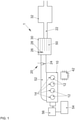
- FIG 1 shows a first exemplary embodiment of a motor vehicle 1 according to the invention with an internal combustion engine 10 and an exhaust system 20.
- the motor vehicle 1 according to the invention is preferably designed as a hybrid vehicle with an internal combustion engine 10 and an electric motor 56, particularly preferably with a spark-ignited spark plug 14 Otto engine.
- Internal combustion engine 10 has at least one combustion chamber 12, preferably as shown in FIG figure 1 shown four combustion chambers 12, which are connected via a common outlet 52 with an exhaust gas channel 22 of the exhaust system 20.
- the internal combustion engine 10 is preferably designed as a reciprocating piston engine, but can also be designed as a rotary piston engine.
- the internal combustion engine 10 is preferably configured as an internal combustion engine 10 charged by means of an exhaust gas turbocharger or as a naturally aspirated engine.
- the exhaust system 20 has an electrically heatable lambda probe 24 in the exhaust gas duct 22 .
- An electrically heatable catalytic converter 30 with a temperature sensor 26, an electric heating element 28 and an oxygen store (oxygen storage capacity - SOC) 50 is arranged in the exhaust gas duct 22 downstream of the lambda probe 24 .
- the electrically heatable catalytic converter 30 is preferably designed as an electrically conductive four-way catalytic converter 30 with an integrated particle filter, the catalytic converter 30 itself acting as a heating resistor 28 when an electrical voltage is applied.
- a further catalytic converter 32 preferably a three-way catalytic converter, is arranged in the exhaust gas duct 22 downstream of the electrically heatable catalytic converter 30 .
- the electrically heatable lambda probe 24, the temperature sensor 26 and the electric heating element 28 of the electrically heatable catalytic converter can be controlled via a control unit 42, preferably via the engine control unit of the internal combustion engine 10 or a power control unit of the hybrid vehicle.
- the control unit 42 is designed in particular to adjust the temperature of the electrically heatable lambda probe 24 .
- the control unit can preferably set the temperature of lambda probe 24 independently of a measuring operation of lambda probe 24 via an electric heating element integrated in lambda probe 24, in particular before the start of measuring operation of lambda probe 24.
- the electric drive motor 56 of the hybrid vehicle is supplied with voltage via a battery 54, which can also be used to heat up the electric heating element 28 of the catalytic converter and/or to heat up the lambda probe 24, if necessary using a voltage converter.
- FIG 2 a further illustration of a motor vehicle 1 according to the invention is shown.
- the motor vehicle 1 has an internal combustion engine 10 with an exhaust system 20 .
- an electrically heatable lambda probe 24 In the exhaust system 20, in the flow direction of an exhaust gas of the internal combustion engine 10 through the exhaust gas duct 22, there is an electrically heatable lambda probe 24, an electrically heatable catalytic converter 30 with a temperature sensor 26 and an electric heating element 28, and downstream of the electrically heatable catalytic converter 30 there is a second catalytic converter 32, which as a three- Way catalyst is formed, arranged.
- the motor vehicle 1 has a plurality of sensors 44, 46, 48 which are designed to send a first control signal to a control unit 42 of the motor vehicle 1.
- a door contact switch 44 a receiver for a keyless locking system of the motor vehicle 46 and a seat belt buckle sensor 48 are shown by way of example.
- other sensors can also be provided, for example a receiver for the transmitter of a central locking system, a sensor 58 for detecting whether a seat is occupied, or a charge state sensor of the battery system 56 .
- the control device 42 receives a first control signal which indicates that the engine of the internal combustion engine 10 is about to start.
- the first control signal can, for example from one of the in figure 2 sensors 44, 46 or 48, 58 shown have been generated.
- control unit 42 controls an electric heating element integrated in heatable lambda probe 24 in such a way that it heats lambda probe 24 .
- the lambda probe 24 is heated well before the engine starts of the internal combustion engine 10.
- the In a first phase the lambda probe is heated up to its operating temperature T 1 by time B, so that the lambda probe 24 is ready for regulation for the entire period VII.
- control unit 42 also regulates electric heating element 28 of catalytic converter 30 in such a way that in the first phase, up to time A, it is heated purely electrically to a temperature T 2 .
- the temperature T 2 is below the light-off temperature of the catalytic converter 30, but still allows a limited exothermic conversion of fuel and oxygen on the catalytic surface of the catalytic converter.
- the light-off temperature is the temperature at which the catalytic converter converts 50% of the exhaust gas components entering the catalytic converter.
- the catalytic converter 30 preferably enables 15%, more preferably 25% and particularly preferably 35% of the exhaust gas components entering the catalytic converter to be converted.
- the catalytic converter has therefore not yet reached its full operational readiness for converting HC, CO and NO x emissions.
- the electrically heatable lambda probe 24 is heated exclusively by means of the electric heating element integrated therein.
- the electrically heatable catalytic converter 30 is heated at least up to time B by means of the integrated heating element 28, preferably also beyond that and/or during the entire period I.
- the energy for electrically heating the lambda probe 24 and the catalytic converter 30 is preferably provided by the battery system 56. if necessary using a voltage converter.
- the electrical preheating takes place in the time period A to B, during which the hybrid vehicle is driven exclusively by the electric drive motor 56 and the internal combustion engine 10 is inactive.
- the internal combustion engine 10 is started and, in a phase II, operated in a lambda-regulated lean mode with a setpoint lambda ⁇ >1.
- An oxygen concentration in the exhaust gas that is precisely determined by means of the lambda probe 24 that is ready for operation is used to Set the air-fuel ratio in the combustion chambers 12 of the internal combustion engine 10 in such a way that the desired target lambda ⁇ >1 is measured with the probe 24 .
- internal combustion engine 10 is operated in such a way that lambda probe 24 continuously determines a setpoint lambda value of 1.1. This slight lean operation causes the untreated HC and CO emissions of the combustion exhaust gases to be reduced. Adequate exhaust gas quality is thus achieved despite the fact that the catalytic converter 30 is not yet fully operational.
- the temperature of catalytic converter 30 increases due to heat transfer from the combustion exhaust gas of internal combustion engine 10 to catalytic converter 30 and possibly due to continued electrical additional heating to a first operating temperature, in particular a light-off temperature, of catalytic converter 30.
- the first operating temperature of the catalytic converter 30 is in figure 3 For reasons of clarity, it is shown as being identical to the operating temperature T 1 of the lambda probe. In reality, however, these temperatures can deviate from each other.
- the internal combustion engine 10 is operated stoichiometrically in a lambda-controlled phase III.
- the untreated exhaust emissions are optimally converted into less harmful compounds in the catalytic converter 30.
- the catalytic converter 30 is heated up further, among other things due to the heat transfer from the combustion exhaust gas of the internal combustion engine 10 to the catalytic converter 30.
- the temperature increase in the catalytic converter 30 in phase III can be lower than the temperature increase in the catalytic converter 30 in phase II or identical to this one.
- the in figure 3 shown period C to D (phase III) longer than the period B to C (phase II).
- the temperature of the catalytic converter 30 rises to a second operating temperature T 3 at time D by the end of phase III.
- the second operating temperature T 3 is an activation temperature of the oxygen accumulator 50, which above this temperature is able to incorporate oxygen into its structure and remove it again with high efficiency.
- the rate of oxygen uptake and release depends on the oxygen loading of the oxygen store 50 and on the oxygen partial pressure of the exhaust gas fed into the catalytic converter 30 .
- the internal combustion engine 10 is operated in a phase IV with lambda control stoichiometrically with an oscillating setpoint lambda value.
- This alternating operation of the internal combustion engine 10 with an alternating slightly rich and slightly lean mixture leads to an optimal utilization of the oxygen accumulator 50, which ensures the exhaust gas quality in particular during load changes and dampens the lambda-controlled stoichiometric operation.
- phase VII which extends from starting engine 10 at point in time B at least until the second operating temperature T 3 of catalytic converter 30 is reached at point in time C (represented by dashed line in the figure 3 ), alternatively also extending up to time D, operated with increased ignition energy.
- the operation with increased ignition energy also preferably extends into phase IV.
- the ignition energy is at the latest during normal operation of the internal combustion engine 10, which is in figure 3 phase IV shown begins or follows, is adjusted to normal levels. In particular, operation takes place with increased ignition energy through the use of spark band ignition, at least during phases II, III and at least partially also during phase IV.
- the combination of the figure 3 provides a method for starting up an internal combustion engine 10 with optimum raw emission reduction directly after a cold start and optimum pollutant conversion in the warm-up phase. This is achieved in that the controllability of the lambda probe 24 is already fully available when the engine is started and the lambda-controlled operation in phases II, III and IV thus takes place with advantageously increased precision.
- the exhaust gas conversion is preferably further improved in that the temperature of the electrically heatable catalytic converter 30 is already above a first threshold temperature T 2 at time B when the engine is started. Above this temperature, the catalytic converter is able, at least to a limited extent, to convert the exhaust components entering the catalytic converter.
- FIG figure 4 shows an alternative embodiment of FIG figure 1 illustrated motor vehicle 1.
- the figure 4 shows an alternative embodiment of FIG figure 1 illustrated motor vehicle 1.
- the internal combustion engine 10 and the exhaust system 20 of the internal combustion engine 10 are shown.
- a three-way catalytic converter (TWC) 30 is arranged instead of the electrically heatable four-way catalytic converter, and a particulate filter 36 is additionally arranged downstream of this TWC 30 and the second catalytic converter 32.
- an additional particle filter 36 can also be arranged upstream of the second catalytic converter 32 .
- the functionality of the second three-way catalytic converter 32 and the particle filter 36 can also be combined in one component and a four-way catalytic converter 32 can be arranged in the exhaust gas duct 22 downstream of an electrically heatable three-way catalytic converter 30 .
- the heatable lambda probe 24 is arranged upstream of a preferably heatable three-way catalytic converter 32 and a particle filter 36, with a four-way catalytic converter 30 also being dispensed with.
- the heatable lambda probe 24 can also be arranged in an exhaust system 20 in combination with only a single heatable or non-heatable three-way catalytic converter or a single heatable or non-heatable four-way catalytic converter.
- Two heatable or non-heatable three-way catalytic converters are also preferably arranged downstream of the heatable lambda probe 24 .
- a likewise preferred embodiment of the exhaust system 20 corresponds to that in figure 1 shown embodiment, the order of the arrangement of three-way catalytic converter 32 and four-way catalytic converter 30 in the exhaust line 22 are interchanged.
Landscapes
- Engineering & Computer Science (AREA)
- Chemical & Material Sciences (AREA)
- Mechanical Engineering (AREA)
- Combustion & Propulsion (AREA)
- General Engineering & Computer Science (AREA)
- Transportation (AREA)
- Chemical Kinetics & Catalysis (AREA)
- Health & Medical Sciences (AREA)
- Toxicology (AREA)
- Power Engineering (AREA)
- Life Sciences & Earth Sciences (AREA)
- Sustainable Energy (AREA)
- Sustainable Development (AREA)
- Automation & Control Theory (AREA)
- Emergency Medicine (AREA)
- Exhaust Gas After Treatment (AREA)
Claims (10)
- Procédé pour faire fonctionner un moteur à combustion interne (10) qui comporte un système de gaz d'échappement (20) qui lui est raccordé, présentant une sonde lambda (24) à chauffage électrique et un catalyseur (30) équipé d'un accumulateur d'oxygène (50), ainsi qu'un appareil de commande (42), le procédé présentant les étapes de :- chauffage électrique de la sonde lambda (24) lorsque le moteur à combustion interne (10) est éteint, après réception d'un premier signal de commande par le biais de l'appareil de commande (42),- démarrage du moteur à combustion interne (10) après avoir atteint une température de fonctionnement de la sonde lambda (24) et un fonctionnement en mode pauvre à régulation lambda du moteur à combustion interne (10),- fonctionnement stœchiométrique à régulation lambda du moteur à combustion interne (10) après avoir atteint une première température de fonctionnement du catalyseur (30) et- fonctionnement stœchiométrique à régulation lambda du moteur à combustion interne (10) avec une valeur lambda de consigne oscillante après avoir atteint une deuxième température de fonctionnement du catalyseur (30).
- Procédé selon la revendication 1, dans lequel la première température de fonctionnement du catalyseur (30) est une température de réchauffage du catalyseur (30) et la deuxième température de fonctionnement du catalyseur (30) est une température d'activation de l'accumulateur d'oxygène (50).
- Procédé selon la revendication 1 ou 2, dans lequel en fonctionnement en mode pauvre à régulation lambda du moteur à combustion interne (10) une valeur lambda de consigne est comprise entre 1,05 et 1,15.
- Procédé selon l'une quelconque des revendications précédentes, dans lequel la valeur lambda de consigne alterne entre 0,98 et 1,02 après avoir atteint la deuxième température de fonctionnement.
- Procédé selon l'une quelconque des revendications précédentes, dans lequel le moteur à combustion interne (10) est actionné avec une énergie d'allumage accrue en fonctionnement en mode pauvre jusqu'à atteindre la première température de fonctionnement du catalyseur (30).
- Procédé selon l'une quelconque des revendications précédentes, dans lequel le catalyseur (30) comporte en outre un élément chauffant électrique (28) et le catalyseur (30) est chauffé électriquement après réception du premier signal de commande.
- Procédé selon l'une quelconque des revendications précédentes, dans lequel l'atteinte de la première température de fonctionnement du catalyseur (30) et/ou la deuxième température de fonctionnement du catalyseur (30) est déterminée à l'aide d'une température mesurée dans ou au niveau du catalyseur (30) au moyen d'un capteur de température (26) ou à l'aide d'un modèle de température de gaz d'échappement.
- Procédé selon l'une quelconque des revendications précédentes, dans lequel le premier signal de commande est généré par un contacteur de porte (44), un récepteur (46) pour un signal d'un système de fermeture sans clé ou d'un verrouillage centralisé, un contacteur de ceinture (48) ou un capteur d'état de charge d'un système de batterie (54).
- Véhicule automobile (1) comprenant un moteur à combustion interne (10), un système de gaz d'échappement (20) qui lui est raccordé, présentant une sonde lambda (24) à chauffage électrique et un catalyseur (30) comportant un accumulateur d'oxygène (50) et un appareil de commande (42), l'appareil de commande (42) étant conçu pour exécuter un procédé selon l'une quelconque des revendications 1 à 8.
- Véhicule automobile (1) selon la revendication 9, comportant en outre un moteur de propulsion (56) alimenté électriquement par un système de batterie (54), le système de batterie (54) présentant un capteur d'état de charge destiné à émettre le premier signal de commande.
Applications Claiming Priority (2)
| Application Number | Priority Date | Filing Date | Title |
|---|---|---|---|
| DE102017107678.6A DE102017107678A1 (de) | 2017-04-10 | 2017-04-10 | Verfahren zur Inbetriebnahme eines Verbrennungsmotors und Kraftfahrzeug mit einem Verbrennungsmotor |
| PCT/EP2018/058838 WO2018189047A1 (fr) | 2017-04-10 | 2018-04-06 | Procédé pour faire fonctionner un moteur à combustion interne et véhicule automobile équipé d'un moteur à combustion interne |
Publications (2)
| Publication Number | Publication Date |
|---|---|
| EP3610148A1 EP3610148A1 (fr) | 2020-02-19 |
| EP3610148B1 true EP3610148B1 (fr) | 2022-03-02 |
Family
ID=61965968
Family Applications (1)
| Application Number | Title | Priority Date | Filing Date |
|---|---|---|---|
| EP18717306.7A Active EP3610148B1 (fr) | 2017-04-10 | 2018-04-06 | Procédé pour faire fonctionner un moteur à combustion interne et véhicule automobile équipé d'un moteur à combustion interne |
Country Status (5)
| Country | Link |
|---|---|
| US (1) | US11060473B2 (fr) |
| EP (1) | EP3610148B1 (fr) |
| CN (1) | CN110462188B (fr) |
| DE (1) | DE102017107678A1 (fr) |
| WO (1) | WO2018189047A1 (fr) |
Families Citing this family (5)
| Publication number | Priority date | Publication date | Assignee | Title |
|---|---|---|---|---|
| DE102018112263A1 (de) | 2018-05-22 | 2019-11-28 | Volkswagen Aktiengesellschaft | Verfahren und Vorrichtung zur Abgasnachbehandlung eines Verbrennungsmotors |
| FR3100566B1 (fr) * | 2019-09-11 | 2022-07-22 | Renault Sas | Procede de traitement de polluants par catalyseur trois voies au demarrage d’un moteur a combustion |
| DE102021103481A1 (de) * | 2021-02-15 | 2022-08-18 | Audi Aktiengesellschaft | Verfahren zur Bereitstellung einer Leistungsversorgung wenigstens eines in einem Abgasstrang angeordneten und elektrisch heizbaren Katalysators eines Kraftfahrzeugs,Kraftfahrzeug umfassend wenigstens einen elektrisch heizbaren und in einem Abgasstrang des Kraftfahrzeugs angeordneten Katalysator |
| EP4112899B1 (fr) | 2021-07-02 | 2023-12-27 | Volvo Truck Corporation | Commande du contrôle des émissions de nox pendant le démarrage d'un véhicule |
| US11519313B1 (en) | 2021-08-04 | 2022-12-06 | Ford Global Technologies, Llc | Methods and systems for engine exhaust catalyst operations |
Citations (1)
| Publication number | Priority date | Publication date | Assignee | Title |
|---|---|---|---|---|
| US20090301437A1 (en) * | 2006-02-07 | 2009-12-10 | Hiroaki Mizoguchi | Air-fuel ratio control device of internal combustion engine |
Family Cites Families (19)
| Publication number | Priority date | Publication date | Assignee | Title |
|---|---|---|---|---|
| DE4019067A1 (de) * | 1990-06-15 | 1991-12-19 | Bosch Gmbh Robert | Einrichtung zum einschalten einer abgassondenheizung |
| DE4223954C1 (de) * | 1992-07-21 | 1994-01-13 | Bosch Gmbh Robert | Vorrichtung zum Steuern eines Heizelements in einem Kraftfahrzeug |
| DE4331853C2 (de) | 1992-09-26 | 2001-12-06 | Volkswagen Ag | Brennkraftmaschine |
| JP3467795B2 (ja) * | 1993-03-11 | 2003-11-17 | マツダ株式会社 | エンジンの排気浄化装置 |
| EP1182340B1 (fr) | 2000-08-22 | 2005-06-08 | Mazda Motor Corporation | Système de purification de gaz d'échappement pour un moteur à combustion interne |
| DE10115968B4 (de) | 2001-03-27 | 2012-08-16 | Volkswagen Ag | Verfahren zur Erwärmung eines Katalysators |
| US6898927B2 (en) * | 2001-10-16 | 2005-05-31 | Denso Corporation | Emission control system with catalyst warm-up speeding control |
| US7043901B2 (en) * | 2003-03-20 | 2006-05-16 | Ford Global Technologies, Llc | Device and method for internal combustion engine control |
| JP2005264891A (ja) * | 2004-03-22 | 2005-09-29 | Mikuni Corp | 酸素センサ用加熱ヒータ制御装置 |
| US8209970B2 (en) * | 2007-05-15 | 2012-07-03 | GM Global Technology Operations LLC | Hybrid cold start strategy using electrically heated catalyst |
| US8584650B2 (en) | 2007-11-07 | 2013-11-19 | Ford Global Technologies, Llc | Ignition energy control for mixed fuel engine |
| JP2010190203A (ja) * | 2009-02-20 | 2010-09-02 | Toyota Motor Corp | 内燃機関の排気浄化装置 |
| DE102009045446A1 (de) * | 2009-10-07 | 2011-04-14 | Robert Bosch Gmbh | Lambdasonden-Betriebsverfahren und Vorrichtung zur Durchführung des Verfahrens |
| EP2653683B1 (fr) * | 2010-12-15 | 2017-01-25 | Toyota Jidosha Kabushiki Kaisha | Appareil de détection de défaillance pour un catalyseur chauffé électriquement |
| DE102012205017A1 (de) | 2011-04-28 | 2012-10-31 | Robert Bosch Gmbh | Verfahren zum Betreiben einer Brennkraftmaschine |
| DE102013216024B4 (de) | 2013-08-13 | 2022-01-27 | Volkswagen Aktiengesellschaft | Verfahren zur Lambda-Regelung einer Verbrennungskraftmaschine und Regelvorrichtung |
| DE102013221595A1 (de) * | 2013-10-24 | 2015-04-30 | Robert Bosch Gmbh | Verfahren und Vorrichtung zur Verminderung der Emissionen einer Brennkraftmaschine |
| CN105102797B (zh) | 2014-03-10 | 2017-11-14 | 本田技研工业株式会社 | 内燃机的燃烧控制装置 |
| DE102016202854A1 (de) | 2016-02-24 | 2017-08-24 | Volkswagen Aktiengesellschaft | Verfahren und Vorrichtung zum Betreiben einer Lambdasonde in einem Abgaskanal einer Brennkraftmaschine |
-
2017
- 2017-04-10 DE DE102017107678.6A patent/DE102017107678A1/de not_active Withdrawn
-
2018
- 2018-04-06 US US16/603,518 patent/US11060473B2/en active Active
- 2018-04-06 WO PCT/EP2018/058838 patent/WO2018189047A1/fr not_active Ceased
- 2018-04-06 CN CN201880024239.9A patent/CN110462188B/zh active Active
- 2018-04-06 EP EP18717306.7A patent/EP3610148B1/fr active Active
Patent Citations (1)
| Publication number | Priority date | Publication date | Assignee | Title |
|---|---|---|---|---|
| US20090301437A1 (en) * | 2006-02-07 | 2009-12-10 | Hiroaki Mizoguchi | Air-fuel ratio control device of internal combustion engine |
Also Published As
| Publication number | Publication date |
|---|---|
| US11060473B2 (en) | 2021-07-13 |
| CN110462188A (zh) | 2019-11-15 |
| EP3610148A1 (fr) | 2020-02-19 |
| DE102017107678A1 (de) | 2018-10-11 |
| US20210087990A1 (en) | 2021-03-25 |
| CN110462188B (zh) | 2022-03-22 |
| WO2018189047A1 (fr) | 2018-10-18 |
Similar Documents
| Publication | Publication Date | Title |
|---|---|---|
| EP3610148B1 (fr) | Procédé pour faire fonctionner un moteur à combustion interne et véhicule automobile équipé d'un moteur à combustion interne | |
| EP3642460B1 (fr) | Système de retraitement des gaz d'échappement et procédé pour le retraitement des gaz d'échappement d'un moteur a combustion interne | |
| EP3665371B1 (fr) | Système et procédé de posttraitement de gaz d'échappement d'un moteur à combustion interne | |
| EP3475543B1 (fr) | Procédé et dispositif de post-traitement de gaz d'échappement d'un moteur à combustion interne | |
| DE102016122304A1 (de) | Verfahren zum Aufheizen eines Katalysators sowie Kraftfahrzeug mit einem Katalysator | |
| EP3921520B1 (fr) | Système de post-traitement de gaz d'échappement et procédé pour le post-traitement de gaz d'échappement d'un moteur à combustion interne | |
| DE102017107378A1 (de) | Verfahren zum Aufheizen eines Katalysators sowie Kraftfahrzeug mit einem Katalysator | |
| EP3581771B1 (fr) | Système de traitement de gaz d'échappement et procédé de régénération d'un filtre à particules | |
| EP3508704A1 (fr) | Système de retraitement des gaz d'échappement et procédé de retraitement des gaz d'échappement d'un moteur à combustion interne | |
| EP3608519B1 (fr) | Procédé et dispositif de traitement d'échappement d'un moteur à combustion | |
| EP3412880A1 (fr) | Methode de regeneration d'un filtre a particules dans l'echappement d'un moteur de combustion interne | |
| EP2150686B1 (fr) | Procédé de fonctionnement d'un véhicule à moteur équipé d'un dispositif de chauffe des gaz d'échappement | |
| EP3652420A1 (fr) | Système et procédé de retraitement des gaz d'échappement d'un moteur à combustion interne | |
| WO2020069549A1 (fr) | Système de moteur à allumage commandé et procédé à système nsc | |
| WO2018134151A1 (fr) | Régénération d'un filtre à particules ou d'un pot catalytique à quatre voies dans un système d'échappement d'un moteur à combustion interne | |
| DE102021113252B4 (de) | Verfahren zur Steuerung eines Verbrennungsmotors mit Abgasnachbehandlungssystem | |
| DE102017115399A1 (de) | Abgasnachbehandlungssystem und Verfahren zur Abgasnachbehandlung eines Verbrennungsmotors | |
| DE102020126717A1 (de) | Verfahren zur Abgasnachbehandlung eines Verbrennungsmotors sowie Kraftfahrzeug mit einem solchen Abgasnachbehandlungssystem | |
| EP3569850A1 (fr) | Procédé de réduction des émissions de particules lors d'un démarrage à froid d'un moteur à combustion interne | |
| DE102016119211A1 (de) | Vorrichtung und Verfahren zur Abgasnachbehandlung eines Verbrennungsmotors | |
| DE102017208671A1 (de) | Verfahren zur Abgasnachbehandlung eines Verbrennungsmotors sowie Abgasnachbehandlungssystem | |
| DE102017101610A1 (de) | Verfahren zur Reduzierung der Kaltstart-Emissionen bei einem fremdgezündeten Verbrennungsmotor | |
| DE102017210880A1 (de) | Verfahren zum Aufheizen eines Katalysators in einer Abgasanlage eines Verbrennungsmotors sowie Abgasnachbehandlungssystem | |
| EP3833858B1 (fr) | Procédé et dispositif de post-traitement de gaz d'échappement d'un moteur à combustion interne | |
| DE102023112703A1 (de) | Verfahren zur emissionsoptimierten Steuerung eines Verbrennungsmotors |
Legal Events
| Date | Code | Title | Description |
|---|---|---|---|
| STAA | Information on the status of an ep patent application or granted ep patent |
Free format text: STATUS: UNKNOWN |
|
| STAA | Information on the status of an ep patent application or granted ep patent |
Free format text: STATUS: THE INTERNATIONAL PUBLICATION HAS BEEN MADE |
|
| PUAI | Public reference made under article 153(3) epc to a published international application that has entered the european phase |
Free format text: ORIGINAL CODE: 0009012 |
|
| STAA | Information on the status of an ep patent application or granted ep patent |
Free format text: STATUS: REQUEST FOR EXAMINATION WAS MADE |
|
| 17P | Request for examination filed |
Effective date: 20191111 |
|
| AK | Designated contracting states |
Kind code of ref document: A1 Designated state(s): AL AT BE BG CH CY CZ DE DK EE ES FI FR GB GR HR HU IE IS IT LI LT LU LV MC MK MT NL NO PL PT RO RS SE SI SK SM TR |
|
| AX | Request for extension of the european patent |
Extension state: BA ME |
|
| DAV | Request for validation of the european patent (deleted) | ||
| DAX | Request for extension of the european patent (deleted) | ||
| GRAP | Despatch of communication of intention to grant a patent |
Free format text: ORIGINAL CODE: EPIDOSNIGR1 |
|
| STAA | Information on the status of an ep patent application or granted ep patent |
Free format text: STATUS: GRANT OF PATENT IS INTENDED |
|
| INTG | Intention to grant announced |
Effective date: 20211005 |
|
| GRAS | Grant fee paid |
Free format text: ORIGINAL CODE: EPIDOSNIGR3 |
|
| GRAA | (expected) grant |
Free format text: ORIGINAL CODE: 0009210 |
|
| STAA | Information on the status of an ep patent application or granted ep patent |
Free format text: STATUS: THE PATENT HAS BEEN GRANTED |
|
| AK | Designated contracting states |
Kind code of ref document: B1 Designated state(s): AL AT BE BG CH CY CZ DE DK EE ES FI FR GB GR HR HU IE IS IT LI LT LU LV MC MK MT NL NO PL PT RO RS SE SI SK SM TR |
|
| REG | Reference to a national code |
Ref country code: GB Ref legal event code: FG4D Free format text: NOT ENGLISH |
|
| REG | Reference to a national code |
Ref country code: CH Ref legal event code: EP Ref country code: AT Ref legal event code: REF Ref document number: 1472423 Country of ref document: AT Kind code of ref document: T Effective date: 20220315 |
|
| REG | Reference to a national code |
Ref country code: DE Ref legal event code: R096 Ref document number: 502018008929 Country of ref document: DE |
|
| REG | Reference to a national code |
Ref country code: IE Ref legal event code: FG4D Free format text: LANGUAGE OF EP DOCUMENT: GERMAN |
|
| REG | Reference to a national code |
Ref country code: LT Ref legal event code: MG9D |
|
| REG | Reference to a national code |
Ref country code: NL Ref legal event code: MP Effective date: 20220302 |
|
| PG25 | Lapsed in a contracting state [announced via postgrant information from national office to epo] |
Ref country code: SE Free format text: LAPSE BECAUSE OF FAILURE TO SUBMIT A TRANSLATION OF THE DESCRIPTION OR TO PAY THE FEE WITHIN THE PRESCRIBED TIME-LIMIT Effective date: 20220302 Ref country code: RS Free format text: LAPSE BECAUSE OF FAILURE TO SUBMIT A TRANSLATION OF THE DESCRIPTION OR TO PAY THE FEE WITHIN THE PRESCRIBED TIME-LIMIT Effective date: 20220302 Ref country code: NO Free format text: LAPSE BECAUSE OF FAILURE TO SUBMIT A TRANSLATION OF THE DESCRIPTION OR TO PAY THE FEE WITHIN THE PRESCRIBED TIME-LIMIT Effective date: 20220602 Ref country code: LT Free format text: LAPSE BECAUSE OF FAILURE TO SUBMIT A TRANSLATION OF THE DESCRIPTION OR TO PAY THE FEE WITHIN THE PRESCRIBED TIME-LIMIT Effective date: 20220302 Ref country code: HR Free format text: LAPSE BECAUSE OF FAILURE TO SUBMIT A TRANSLATION OF THE DESCRIPTION OR TO PAY THE FEE WITHIN THE PRESCRIBED TIME-LIMIT Effective date: 20220302 Ref country code: ES Free format text: LAPSE BECAUSE OF FAILURE TO SUBMIT A TRANSLATION OF THE DESCRIPTION OR TO PAY THE FEE WITHIN THE PRESCRIBED TIME-LIMIT Effective date: 20220302 Ref country code: BG Free format text: LAPSE BECAUSE OF FAILURE TO SUBMIT A TRANSLATION OF THE DESCRIPTION OR TO PAY THE FEE WITHIN THE PRESCRIBED TIME-LIMIT Effective date: 20220602 |
|
| PG25 | Lapsed in a contracting state [announced via postgrant information from national office to epo] |
Ref country code: PL Free format text: LAPSE BECAUSE OF FAILURE TO SUBMIT A TRANSLATION OF THE DESCRIPTION OR TO PAY THE FEE WITHIN THE PRESCRIBED TIME-LIMIT Effective date: 20220302 Ref country code: LV Free format text: LAPSE BECAUSE OF FAILURE TO SUBMIT A TRANSLATION OF THE DESCRIPTION OR TO PAY THE FEE WITHIN THE PRESCRIBED TIME-LIMIT Effective date: 20220302 Ref country code: GR Free format text: LAPSE BECAUSE OF FAILURE TO SUBMIT A TRANSLATION OF THE DESCRIPTION OR TO PAY THE FEE WITHIN THE PRESCRIBED TIME-LIMIT Effective date: 20220603 Ref country code: FI Free format text: LAPSE BECAUSE OF FAILURE TO SUBMIT A TRANSLATION OF THE DESCRIPTION OR TO PAY THE FEE WITHIN THE PRESCRIBED TIME-LIMIT Effective date: 20220302 |
|
| PG25 | Lapsed in a contracting state [announced via postgrant information from national office to epo] |
Ref country code: NL Free format text: LAPSE BECAUSE OF FAILURE TO SUBMIT A TRANSLATION OF THE DESCRIPTION OR TO PAY THE FEE WITHIN THE PRESCRIBED TIME-LIMIT Effective date: 20220302 |
|
| PG25 | Lapsed in a contracting state [announced via postgrant information from national office to epo] |
Ref country code: SM Free format text: LAPSE BECAUSE OF FAILURE TO SUBMIT A TRANSLATION OF THE DESCRIPTION OR TO PAY THE FEE WITHIN THE PRESCRIBED TIME-LIMIT Effective date: 20220302 Ref country code: SK Free format text: LAPSE BECAUSE OF FAILURE TO SUBMIT A TRANSLATION OF THE DESCRIPTION OR TO PAY THE FEE WITHIN THE PRESCRIBED TIME-LIMIT Effective date: 20220302 Ref country code: RO Free format text: LAPSE BECAUSE OF FAILURE TO SUBMIT A TRANSLATION OF THE DESCRIPTION OR TO PAY THE FEE WITHIN THE PRESCRIBED TIME-LIMIT Effective date: 20220302 Ref country code: PT Free format text: LAPSE BECAUSE OF FAILURE TO SUBMIT A TRANSLATION OF THE DESCRIPTION OR TO PAY THE FEE WITHIN THE PRESCRIBED TIME-LIMIT Effective date: 20220704 Ref country code: EE Free format text: LAPSE BECAUSE OF FAILURE TO SUBMIT A TRANSLATION OF THE DESCRIPTION OR TO PAY THE FEE WITHIN THE PRESCRIBED TIME-LIMIT Effective date: 20220302 Ref country code: CZ Free format text: LAPSE BECAUSE OF FAILURE TO SUBMIT A TRANSLATION OF THE DESCRIPTION OR TO PAY THE FEE WITHIN THE PRESCRIBED TIME-LIMIT Effective date: 20220302 |
|
| PG25 | Lapsed in a contracting state [announced via postgrant information from national office to epo] |
Ref country code: IS Free format text: LAPSE BECAUSE OF FAILURE TO SUBMIT A TRANSLATION OF THE DESCRIPTION OR TO PAY THE FEE WITHIN THE PRESCRIBED TIME-LIMIT Effective date: 20220702 Ref country code: AL Free format text: LAPSE BECAUSE OF FAILURE TO SUBMIT A TRANSLATION OF THE DESCRIPTION OR TO PAY THE FEE WITHIN THE PRESCRIBED TIME-LIMIT Effective date: 20220302 |
|
| REG | Reference to a national code |
Ref country code: CH Ref legal event code: PL |
|
| REG | Reference to a national code |
Ref country code: DE Ref legal event code: R097 Ref document number: 502018008929 Country of ref document: DE |
|
| REG | Reference to a national code |
Ref country code: BE Ref legal event code: MM Effective date: 20220430 |
|
| PLBE | No opposition filed within time limit |
Free format text: ORIGINAL CODE: 0009261 |
|
| STAA | Information on the status of an ep patent application or granted ep patent |
Free format text: STATUS: NO OPPOSITION FILED WITHIN TIME LIMIT |
|
| REG | Reference to a national code |
Ref country code: DE Ref legal event code: R082 Ref document number: 502018008929 Country of ref document: DE |
|
| PG25 | Lapsed in a contracting state [announced via postgrant information from national office to epo] |
Ref country code: MC Free format text: LAPSE BECAUSE OF FAILURE TO SUBMIT A TRANSLATION OF THE DESCRIPTION OR TO PAY THE FEE WITHIN THE PRESCRIBED TIME-LIMIT Effective date: 20220302 Ref country code: LU Free format text: LAPSE BECAUSE OF NON-PAYMENT OF DUE FEES Effective date: 20220406 Ref country code: LI Free format text: LAPSE BECAUSE OF NON-PAYMENT OF DUE FEES Effective date: 20220430 Ref country code: DK Free format text: LAPSE BECAUSE OF FAILURE TO SUBMIT A TRANSLATION OF THE DESCRIPTION OR TO PAY THE FEE WITHIN THE PRESCRIBED TIME-LIMIT Effective date: 20220302 Ref country code: CH Free format text: LAPSE BECAUSE OF NON-PAYMENT OF DUE FEES Effective date: 20220430 |
|
| 26N | No opposition filed |
Effective date: 20221205 |
|
| PG25 | Lapsed in a contracting state [announced via postgrant information from national office to epo] |
Ref country code: SI Free format text: LAPSE BECAUSE OF FAILURE TO SUBMIT A TRANSLATION OF THE DESCRIPTION OR TO PAY THE FEE WITHIN THE PRESCRIBED TIME-LIMIT Effective date: 20220302 Ref country code: BE Free format text: LAPSE BECAUSE OF NON-PAYMENT OF DUE FEES Effective date: 20220430 |
|
| PG25 | Lapsed in a contracting state [announced via postgrant information from national office to epo] |
Ref country code: IE Free format text: LAPSE BECAUSE OF NON-PAYMENT OF DUE FEES Effective date: 20220406 |
|
| P01 | Opt-out of the competence of the unified patent court (upc) registered |
Effective date: 20230523 |
|
| PG25 | Lapsed in a contracting state [announced via postgrant information from national office to epo] |
Ref country code: IT Free format text: LAPSE BECAUSE OF FAILURE TO SUBMIT A TRANSLATION OF THE DESCRIPTION OR TO PAY THE FEE WITHIN THE PRESCRIBED TIME-LIMIT Effective date: 20220302 |
|
| PG25 | Lapsed in a contracting state [announced via postgrant information from national office to epo] |
Ref country code: MK Free format text: LAPSE BECAUSE OF FAILURE TO SUBMIT A TRANSLATION OF THE DESCRIPTION OR TO PAY THE FEE WITHIN THE PRESCRIBED TIME-LIMIT Effective date: 20220302 Ref country code: CY Free format text: LAPSE BECAUSE OF FAILURE TO SUBMIT A TRANSLATION OF THE DESCRIPTION OR TO PAY THE FEE WITHIN THE PRESCRIBED TIME-LIMIT Effective date: 20220302 |
|
| PG25 | Lapsed in a contracting state [announced via postgrant information from national office to epo] |
Ref country code: HU Free format text: LAPSE BECAUSE OF FAILURE TO SUBMIT A TRANSLATION OF THE DESCRIPTION OR TO PAY THE FEE WITHIN THE PRESCRIBED TIME-LIMIT; INVALID AB INITIO Effective date: 20180406 |
|
| REG | Reference to a national code |
Ref country code: AT Ref legal event code: MM01 Ref document number: 1472423 Country of ref document: AT Kind code of ref document: T Effective date: 20230406 |
|
| PG25 | Lapsed in a contracting state [announced via postgrant information from national office to epo] |
Ref country code: AT Free format text: LAPSE BECAUSE OF NON-PAYMENT OF DUE FEES Effective date: 20230406 |
|
| PG25 | Lapsed in a contracting state [announced via postgrant information from national office to epo] |
Ref country code: AT Free format text: LAPSE BECAUSE OF NON-PAYMENT OF DUE FEES Effective date: 20230406 |
|
| PG25 | Lapsed in a contracting state [announced via postgrant information from national office to epo] |
Ref country code: MT Free format text: LAPSE BECAUSE OF FAILURE TO SUBMIT A TRANSLATION OF THE DESCRIPTION OR TO PAY THE FEE WITHIN THE PRESCRIBED TIME-LIMIT Effective date: 20220302 |
|
| PGFP | Annual fee paid to national office [announced via postgrant information from national office to epo] |
Ref country code: DE Payment date: 20250430 Year of fee payment: 8 |
|
| PGFP | Annual fee paid to national office [announced via postgrant information from national office to epo] |
Ref country code: GB Payment date: 20250422 Year of fee payment: 8 |
|
| PGFP | Annual fee paid to national office [announced via postgrant information from national office to epo] |
Ref country code: FR Payment date: 20250424 Year of fee payment: 8 |
|
| PG25 | Lapsed in a contracting state [announced via postgrant information from national office to epo] |
Ref country code: TR Free format text: LAPSE BECAUSE OF FAILURE TO SUBMIT A TRANSLATION OF THE DESCRIPTION OR TO PAY THE FEE WITHIN THE PRESCRIBED TIME-LIMIT Effective date: 20220302 |
|
| PGFP | Annual fee paid to national office [announced via postgrant information from national office to epo] |
Ref country code: AT Payment date: 20260410 Year of fee payment: 5 |