EP3615738B1 - Système à haute vitesse destiné à la lutte contre les mauvaises herbes - Google Patents
Système à haute vitesse destiné à la lutte contre les mauvaises herbes Download PDFInfo
- Publication number
- EP3615738B1 EP3615738B1 EP18724478.5A EP18724478A EP3615738B1 EP 3615738 B1 EP3615738 B1 EP 3615738B1 EP 18724478 A EP18724478 A EP 18724478A EP 3615738 B1 EP3615738 B1 EP 3615738B1
- Authority
- EP
- European Patent Office
- Prior art keywords
- module
- herbicide
- control
- weed
- control unit
- Prior art date
- Legal status (The legal status is an assumption and is not a legal conclusion. Google has not performed a legal analysis and makes no representation as to the accuracy of the status listed.)
- Active
Links
Images




Classifications
-
- B—PERFORMING OPERATIONS; TRANSPORTING
- B05—SPRAYING OR ATOMISING IN GENERAL; APPLYING FLUENT MATERIALS TO SURFACES, IN GENERAL
- B05B—SPRAYING APPARATUS; ATOMISING APPARATUS; NOZZLES
- B05B7/00—Spraying apparatus for discharge of liquids or other fluent materials from two or more sources, e.g. of liquid and air, of powder and gas
- B05B7/02—Spray pistols; Apparatus for discharge
- B05B7/04—Spray pistols; Apparatus for discharge with arrangements for mixing liquids or other fluent materials before discharge
- B05B7/0408—Spray pistols; Apparatus for discharge with arrangements for mixing liquids or other fluent materials before discharge with arrangements for mixing two or more liquids
-
- B—PERFORMING OPERATIONS; TRANSPORTING
- B05—SPRAYING OR ATOMISING IN GENERAL; APPLYING FLUENT MATERIALS TO SURFACES, IN GENERAL
- B05B—SPRAYING APPARATUS; ATOMISING APPARATUS; NOZZLES
- B05B1/00—Nozzles, spray heads or other outlets, with or without auxiliary devices such as valves, heating means
- B05B1/14—Nozzles, spray heads or other outlets, with or without auxiliary devices such as valves, heating means with multiple outlet openings; with strainers in or outside the outlet opening
- B05B1/16—Nozzles, spray heads or other outlets, with or without auxiliary devices such as valves, heating means with multiple outlet openings; with strainers in or outside the outlet opening having selectively- effective outlets
-
- B—PERFORMING OPERATIONS; TRANSPORTING
- B05—SPRAYING OR ATOMISING IN GENERAL; APPLYING FLUENT MATERIALS TO SURFACES, IN GENERAL
- B05B—SPRAYING APPARATUS; ATOMISING APPARATUS; NOZZLES
- B05B1/00—Nozzles, spray heads or other outlets, with or without auxiliary devices such as valves, heating means
- B05B1/14—Nozzles, spray heads or other outlets, with or without auxiliary devices such as valves, heating means with multiple outlet openings; with strainers in or outside the outlet opening
- B05B1/16—Nozzles, spray heads or other outlets, with or without auxiliary devices such as valves, heating means with multiple outlet openings; with strainers in or outside the outlet opening having selectively- effective outlets
- B05B1/169—Nozzles, spray heads or other outlets, with or without auxiliary devices such as valves, heating means with multiple outlet openings; with strainers in or outside the outlet opening having selectively- effective outlets having three or more selectively effective outlets
-
- B—PERFORMING OPERATIONS; TRANSPORTING
- B05—SPRAYING OR ATOMISING IN GENERAL; APPLYING FLUENT MATERIALS TO SURFACES, IN GENERAL
- B05B—SPRAYING APPARATUS; ATOMISING APPARATUS; NOZZLES
- B05B1/00—Nozzles, spray heads or other outlets, with or without auxiliary devices such as valves, heating means
- B05B1/14—Nozzles, spray heads or other outlets, with or without auxiliary devices such as valves, heating means with multiple outlet openings; with strainers in or outside the outlet opening
- B05B1/20—Perforated pipes or troughs, e.g. spray booms; Outlet elements therefor
-
- B—PERFORMING OPERATIONS; TRANSPORTING
- B05—SPRAYING OR ATOMISING IN GENERAL; APPLYING FLUENT MATERIALS TO SURFACES, IN GENERAL
- B05B—SPRAYING APPARATUS; ATOMISING APPARATUS; NOZZLES
- B05B12/00—Arrangements for controlling delivery; Arrangements for controlling the spray area
- B05B12/004—Arrangements for controlling delivery; Arrangements for controlling the spray area comprising sensors for monitoring the delivery, e.g. by displaying the sensed value or generating an alarm
-
- B—PERFORMING OPERATIONS; TRANSPORTING
- B05—SPRAYING OR ATOMISING IN GENERAL; APPLYING FLUENT MATERIALS TO SURFACES, IN GENERAL
- B05B—SPRAYING APPARATUS; ATOMISING APPARATUS; NOZZLES
- B05B12/00—Arrangements for controlling delivery; Arrangements for controlling the spray area
- B05B12/02—Arrangements for controlling delivery; Arrangements for controlling the spray area for controlling time, or sequence, of delivery
-
- B—PERFORMING OPERATIONS; TRANSPORTING
- B05—SPRAYING OR ATOMISING IN GENERAL; APPLYING FLUENT MATERIALS TO SURFACES, IN GENERAL
- B05B—SPRAYING APPARATUS; ATOMISING APPARATUS; NOZZLES
- B05B12/00—Arrangements for controlling delivery; Arrangements for controlling the spray area
- B05B12/08—Arrangements for controlling delivery; Arrangements for controlling the spray area responsive to condition of liquid or other fluent material to be discharged, of ambient medium or of target ; responsive to condition of spray devices or of supply means, e.g. pipes, pumps or their drive means
-
- B—PERFORMING OPERATIONS; TRANSPORTING
- B05—SPRAYING OR ATOMISING IN GENERAL; APPLYING FLUENT MATERIALS TO SURFACES, IN GENERAL
- B05B—SPRAYING APPARATUS; ATOMISING APPARATUS; NOZZLES
- B05B12/00—Arrangements for controlling delivery; Arrangements for controlling the spray area
- B05B12/08—Arrangements for controlling delivery; Arrangements for controlling the spray area responsive to condition of liquid or other fluent material to be discharged, of ambient medium or of target ; responsive to condition of spray devices or of supply means, e.g. pipes, pumps or their drive means
- B05B12/12—Arrangements for controlling delivery; Arrangements for controlling the spray area responsive to condition of liquid or other fluent material to be discharged, of ambient medium or of target ; responsive to condition of spray devices or of supply means, e.g. pipes, pumps or their drive means responsive to conditions of ambient medium or target, e.g. humidity, temperature position or movement of the target relative to the spray apparatus
- B05B12/122—Arrangements for controlling delivery; Arrangements for controlling the spray area responsive to condition of liquid or other fluent material to be discharged, of ambient medium or of target ; responsive to condition of spray devices or of supply means, e.g. pipes, pumps or their drive means responsive to conditions of ambient medium or target, e.g. humidity, temperature position or movement of the target relative to the spray apparatus responsive to presence or shape of target
-
- B—PERFORMING OPERATIONS; TRANSPORTING
- B05—SPRAYING OR ATOMISING IN GENERAL; APPLYING FLUENT MATERIALS TO SURFACES, IN GENERAL
- B05B—SPRAYING APPARATUS; ATOMISING APPARATUS; NOZZLES
- B05B12/00—Arrangements for controlling delivery; Arrangements for controlling the spray area
- B05B12/08—Arrangements for controlling delivery; Arrangements for controlling the spray area responsive to condition of liquid or other fluent material to be discharged, of ambient medium or of target ; responsive to condition of spray devices or of supply means, e.g. pipes, pumps or their drive means
- B05B12/12—Arrangements for controlling delivery; Arrangements for controlling the spray area responsive to condition of liquid or other fluent material to be discharged, of ambient medium or of target ; responsive to condition of spray devices or of supply means, e.g. pipes, pumps or their drive means responsive to conditions of ambient medium or target, e.g. humidity, temperature position or movement of the target relative to the spray apparatus
- B05B12/124—Arrangements for controlling delivery; Arrangements for controlling the spray area responsive to condition of liquid or other fluent material to be discharged, of ambient medium or of target ; responsive to condition of spray devices or of supply means, e.g. pipes, pumps or their drive means responsive to conditions of ambient medium or target, e.g. humidity, temperature position or movement of the target relative to the spray apparatus responsive to distance between spray apparatus and target
-
- B—PERFORMING OPERATIONS; TRANSPORTING
- B05—SPRAYING OR ATOMISING IN GENERAL; APPLYING FLUENT MATERIALS TO SURFACES, IN GENERAL
- B05B—SPRAYING APPARATUS; ATOMISING APPARATUS; NOZZLES
- B05B12/00—Arrangements for controlling delivery; Arrangements for controlling the spray area
- B05B12/16—Arrangements for controlling delivery; Arrangements for controlling the spray area for controlling the spray area
-
- B—PERFORMING OPERATIONS; TRANSPORTING
- B05—SPRAYING OR ATOMISING IN GENERAL; APPLYING FLUENT MATERIALS TO SURFACES, IN GENERAL
- B05B—SPRAYING APPARATUS; ATOMISING APPARATUS; NOZZLES
- B05B13/00—Machines or plants for applying liquids or other fluent materials to surfaces of objects or other work by spraying, not covered by groups B05B1/00 - B05B11/00
- B05B13/005—Machines or plants for applying liquids or other fluent materials to surfaces of objects or other work by spraying, not covered by groups B05B1/00 - B05B11/00 mounted on vehicles or designed to apply a liquid on a very large surface, e.g. on the road, on the surface of large containers
-
- B—PERFORMING OPERATIONS; TRANSPORTING
- B61—RAILWAYS
- B61D—BODY DETAILS OR KINDS OF RAILWAY VEHICLES
- B61D15/00—Other railway vehicles, e.g. scaffold cars; Adaptations of vehicles for use on railways
-
- E—FIXED CONSTRUCTIONS
- E01—CONSTRUCTION OF ROADS, RAILWAYS, OR BRIDGES
- E01H—STREET CLEANING; CLEANING OF PERMANENT WAYS; CLEANING BEACHES; DISPERSING OR PREVENTING FOG IN GENERAL CLEANING STREET OR RAILWAY FURNITURE OR TUNNEL WALLS
- E01H11/00—Control of undesirable vegetation on roads or similar surfaces or permanent ways of railways, e.g. devices for scorching weeds or for applying herbicides; Applying liquids, e.g. water, weed-killer bitumen, to permanent ways
Definitions
- the invention relates to a modular system for weed control for a rail vehicle, and in particular to a weed control system in track beds that can also be used at high speeds, in particular a spray train with such a system and a method for controlling weeds in a track bed.
- the document EP 2728068 A1 discloses a rail sprayer comprising a motor vehicle, at least one spray container, at least one spray nozzle and at least one vegetation sensor, the at least one vegetation sensor being connected to a control unit.
- the control unit is in turn connected to the at least one spray nozzle.
- WO 2004/005625 A1 describes a connection between a weed-killing machine, which is mounted on a rail vehicle, which is equipped with a weed-detecting camera and a computer connected to it, and a weather unit, which is also connected to the computer.
- the present invention is therefore based on the object of presenting a concept for a system for weed control which is flexible with regard to the control unit used, the camera and the train speeds and can be used at comparatively high travel speeds.
- the spray train for weed control on railways has the modular system according to the invention, as well as one or more carrying wagons, and a second carriage for reversible mounting of the camera module, the second carriage being arranged in one direction of travel in front of the one or more carrying wagons.
- a spray train comprising a modular system for weed control for a rail vehicle.
- the modular system has a control unit, a herbicide and mixing module, a nozzle assembly and a camera module.
- the control unit is designed to generate a first set of control signals for controlling valves and mixers in a separate herbicide and mixing module for mixing a herbicide mixture and for generating a second set of control signals for controlling valves of a nozzle assembly.
- the herbicide and mixing module has containers for receiving different herbicides, which are selectively in fluid communication with the valves and mixers, and connection elements via which electrical signal connections can be made to connection elements of the control unit, so that the first generated in the control unit Control signals can be routed to the valves and mixers of the herbicide and mixing module.
- the nozzle assembly which is spatially independent both of the control unit and of the herbicide and mixing module, has a first set of nozzles for spraying herbicides and a fluid connection to selected ones of the valves and mixers of the herbicide and mixing module .
- the camera module generates a weed signal in response to a detection of a weed.
- the generation of the first set of control signals and the generation of the second set of control signals by the weed signal of the camera module can be controlled by means of the control unit.
- the camera module itself is at a predefined distance from the nozzle assembly, is spatially separated from the control and monitoring module, the herbicide and mixing module and the nozzle assembly and is arranged in front of them in a common direction of movement.
- the spray train has the aforementioned modular system for weed control on one or more carrying wagons and a second wagon for reversible mounting of the camera module.
- the second wagon is arranged in front of the one or more carrying wagons in one direction of travel.
- a method for controlling weeds in a track bed has, in particular, the following: a reversible fixing of a control unit in a control and monitoring module on a carriage, a reversible fixing of a herbicide and mixing module on the carrying carriage, a reversible fixing of a nozzle assembly on the carrying carriage, the nozzle assembly in each case spatially is independent of both the control and monitoring modules and the herbicide and mixing module.
- the method further comprises establishing a fluid connection between the herbicide and mixing module and the nozzle assembly and generating a weed signal by means of a camera module which is arranged at a distance in front of the carrying car in a direction of travel of the carrying car.
- the control unit of the control and monitoring module influences a first set of control signals for controlling valves and mixers in the herbicide and mixing module for mixing a herbicide mixture.
- the influence depends on the weed signal from the camera module.
- the method further comprises influencing a second set of control signals for controlling valves of a nozzle assembly by means of the control unit of the control and monitoring module as a function of the weed signal from the camera module, and selective spraying of the herbicide mixture via nozzles of the nozzle assembly on railways.
- module In the context of the spray train presented, the term "modular system” describes the fact that there are various modules from which weed control for track beds can be put together.
- the individual modules are independent of one another - especially in the case of transport. They can be put together at a target location - i.e., at the place of use for weed control - to form a fully functional system for weed control on railways.
- weed control describes the process of applying herbicides in order to control existing weeds in a targeted manner. Furthermore, in the context of this description, weed control should also be understood as proactive measures; i.e. measures that prevent weeds from appearing in the first place.
- a rail vehicle here describes a wagon and / or a railcar for rail traffic.
- a rail vehicle generally has at least two axles, each with two wheels, which can be placed on two rails running parallel to one another.
- the two axes can be connected to a chassis on which appropriate superstructures (e.g. to accommodate goods or people to be transported) can be placed.
- control unit here denotes a unit which is set up to process input signals and to generate output signals as a function of the input signals.
- the input signals can have different sources, such as, for example, the speed of movement of the control unit with respect to the ground or output signals from the camera module.
- the control unit can also generate output signals in order to provide weed-specific herbicide mixtures by means of the valves and mixers, which can be individually controlled via the output signals of the control unit.
- a further set of output signals, which are sent from the control unit to the nozzles - potentially also mixers and valves - of the nozzle assembly can be used to spray herbicide mixtures in the track bed and the associated embankment.
- the control unit is part of the control and monitoring module, which can be reversibly attached to the carrier.
- nozzles of the nozzle assembly can also be provided for spraying a path running laterally to the embankment.
- control and monitoring module is an independent module which can be understood as the central control module of the presented modular system for weed control for a rail vehicle.
- control and monitoring module essentially all control signals are generated or processed by means of the control unit in order to ensure the overall function of the modular system for weed control for a rail vehicle.
- control unit also allows manual interventions in the herbicide delivery via the nozzle assembly by means of a control station, which can be a functional part of the control unit.
- a module or component is basically not physically attached to another component. Rather, it can be positioned autonomously from the other component in an overall system.
- the nozzle assembly can be attached to the carrier independently of the monitoring and control module and also independently of the herbicide and mixing module.
- Another example relates to the camera module. It can be positioned independently of the other components or modules. For example, it can be mounted on the tank car in front or it can be attached to a drone. Nevertheless, it can have a predefined distance to one of the other modules - for example the nozzle assembly - at any point in time.
- control signal describes an electrical signal which is generated by a controller and which controls the mode of operation of an activator - for example in the form of a valve or a nozzle.
- it can also be a signal on a data line from the camera module to the control unit, which signals to the control unit that a weed in general or a very specific (specific) weed has been recognized.
- the term "herbicide and mixing module” describes a further module of the modular system for weed control for a rail vehicle.
- the herbicide and mixing module has a plurality of containers which can hold different herbicides.
- the herbicide and mixing module can furthermore have various connections: a water connection and a plurality of electrical lines for controlling and monitoring the function of the herbicide and mixing module.
- additional lines can be provided in order to refill one or more of the containers with appropriate herbicides.
- nozzle assembly describes a support frame on which there are a plurality of nozzles for applying the herbicide mixtures.
- the nozzle assembly is a the nozzle assembly has a plurality of preferably electrical and / or pneumatic connections via which the function of the individual nozzles can be controlled.
- the nozzle assembly can have one or more connections for feed lines for the herbicide mixtures and / or water and / or compressed air.
- the nozzle assembly can be reversibly fixed on the carrier element or on the carrying carriage.
- selective fluid connection describes a connection between a source and a sink for a gas or a liquid.
- the selectivity of the fluid connection indicates that the intensity of the connection - i.e. the cross section of the connection or the flow rate and thus the amount of substance transported through the fluid connection can be selectively influenced. Typically, this controlling influence can take place via one or more valves.
- carrier element describes a common basis for the modules of the modular system for weed control for a rail vehicle. Not all modules have to be mounted on - ie, above - the carrier element. They can also be reversibly connectable to the carrier element laterally on or below the carrier element.
- in container construction is directly related to the modular construction of the modular system presented here. All or some of the modules of the modular system can each be integrated in a standard container - for example a standard 20-foot container. Standard containers are preferably understood to mean those containers that are described in ISO standard 668: 2013-08. Of course, other container sizes are also possible.
- container cards is also intended to include modules that can be integrated into a standard container, for example to transport the module integrated into such a standard container using common means (e.g. trucks, aircraft or ships, which are designed for the transport of standard containers) can. It is conceivable, for example, that one or more modules have a platform (base plate) that have the same dimensions as the platform of a standard container and that side walls and a roof wall can be attached to the platform or side walls so that the module can be housed and the enclosed module represents a standard container.
- the advantage of the container design is, among other things, that different modules can be accommodated in a respective container. This applies, for example, to the control and monitoring module, the herbicide and mixing module or even a stay or storage module.
- a “camera module” has at least one electronic camera and evaluation electronics.
- the camera module usually has significantly smaller dimensions than the container-sized modules of the modular system for weed control already described.
- the camera module can be connected to the control unit of the control and monitoring module via electrical connections for data exchange purposes.
- the camera module can either transmit raw image data directly to the control unit or preprocessing of the image data recorded by the camera can take place within the camera. In both cases the camera of the camera module is aimed at the track bed in front of it. In order to ensure the processing of the data of the camera module and to make the necessary herbicides ready for use at the nozzles of the nozzle assembly - for example to transport them there through the fluid connections - the camera module can be provided clearly in front of the nozzle assembly.
- the camera system can have a plurality of individual cameras, which, for example, are either assigned to track bed segments and / or generate weed-specific data and signals.
- the image data from the cameras can be correlated with one another in order to identify weeds in general or specifically even more precisely.
- weed signal can describe one or more electrical signals which, by their nature, indicate the presence of weeds. Based on one of these weed signals, herbicides or herbicide mixtures can be provided for weed control.
- the weed signal can in particular also be a weed-specific weed signal which signals the detection of certain weeds.
- weed-specific weed signal can describe one or more electrical signals which, by their nature, indicate the presence of a certain weed species. Based on one of these weed-specific weed signals, weed-specific herbicides or herbicide mixtures can be provided for targeted control of the corresponding weed species.
- weed-specific herbicide or “weed-specific herbicide mixtures” describes an agent with which specific weeds are controlled.
- the term "energy module” describes another module of the modular system for weed control.
- the energy module can also be in a container design.
- a housing for example a generator for generating electricity, can protect against external influences.
- This housing along with other elements, can be mounted on a platform, which in turn represents a basic platform of a standard container.
- carrying wagon describes a freight wagon in the form of a flat wagon which has a supporting frame but no other fixed superstructures.
- the axles are typically suspended from bogies.
- the term "residence module” describes a further optional module of the modular system for weed control. This module can also be designed as a container. Facilities can be provided in it which are suitable for people to stay - for example for recreation or work purposes.
- intermediate rail nozzle denotes a nozzle which is located in an area above and between the rails on the nozzle assembly. Such a nozzle can essentially spray the track bed between the individual rails.
- embankment nozzle describes a nozzle that is located above or next to the embankment of the track bed on the nozzle block and is set up to spray the embankment of the track bed during use.
- a full jet nozzle generates a spray jet that spreads symmetrically in relation to an axis oriented vertically to the nozzle direction.
- the spray jet of a half-jet nozzle is asymmetrical to the axis oriented vertically to the nozzle direction, so that, for example, a spray jet is created only on one side of the vertically oriented axis.
- This can be achieved by a special shape of the nozzle or by shielding plates.
- the nozzles are designed as spoon nozzles.
- a spoon-shaped shield shields the spray jet when it emerges from the nozzle, for example from the wind of the spray train.
- the concept of the modular system for weed control for a rail vehicle presented here has a number of advantages and technical effects that also apply in a comparable way to the spray train or the corresponding process:
- the modular design of the system presented results in flexible application options in terms of location and time.
- the individual modules can be detached from the wagon at any time in order to then be transported to another location, for example by air freight.
- the system presented can be mounted on a new flat wagon in order to carry out weed control at this destination.
- the modular system is designed for combating weeds at high speeds.
- a camera module is always provided in the immediate vicinity - or at least on the same car - the control unit.
- the computing time required - either in the camera module or in the control unit - for the detection of any or certain (specific) weeds is relatively high, so that the nozzle assembly for the delivery of the herbicides already occurs at comparatively high pulling speeds the recognized weed has passed and the herbicide application would therefore be too late.
- the time available for calculation is the same as the distance between the nozzle assembly and the camera module divided by the speed
- the decisive time contribution for determining the weeds or the weeds is the provision of the herbicide mixture at the nozzles.
- the camera module can be mounted directly on another car on the train. Rather, the camera module can also be mounted on a train traveling ahead, which preferably travels with the nozzle assembly at a constant distance in front of the train. In this case, the data from the camera module can be transmitted wirelessly to the control unit.
- the camera data can be processed in real time to calculate the correct times for dispensing the herbicides through the nozzle assembly. It is therefore not necessary that a complex map (weed map) with the locations of the weeds is generated from the camera data.
- the camera data would be transmitted wirelessly to the control unit; and in this case too, the camera data is processed in real time without the need for a weed map.
- the proposed concept thus allows a significantly higher flexibility with regard to the usable computing speed of the control unit used, which can be lower and thus also cheaper, and at the speed at which the spray train can run.
- the control and monitoring module can accommodate other components in addition to the control unit. This can include workplaces for operating personnel as well as monitors and other monitoring devices or receivers of weather data or data from geographic information systems.
- the carrier element can be a carriage for use on rails.
- a carrying wagon can be a quasi-standardized wagon of a train for carrying loads - such as container-like modules.
- the camera module can be reversibly attached to a car traveling in front of the control unit.
- the car which is coupled in front of the car carrying the nozzle assembly in the direction of travel, can be, for example, a tank car that is suitable for receiving mixed water, which can be made available to the herbicide and mixing module via a hose line.
- the car ahead can also designate the locomotive that pulls the flat car on which the control and monitoring module with the control unit is reversibly fixed.
- the distance between the camera module and the control unit is fixed or known at any point in time.
- the camera module can be attached to a drone or a multicopter - potentially operating autonomously.
- Such an unmanned flying object can fly at a fixed or known time distance from the control unit / nozzle assembly in front of the spray train.
- the platform of the energy module can be used as a take-off and landing area.
- a second flight object with a second camera module can be used, which can take over the task of the flight object to be refueled, so to speak in a "flying change”.
- the flying object can be operated electrically or also have a fuel engine.
- the distance between the flying object and the control unit or the nozzle assembly can be determined and set using GPS navigation. Corresponding processes are known. This variant also does not require the provision of a weed map. Rather, the data from the camera module can be converted directly into the release of herbicides via the nozzle assembly.
- the camera module can be attached to a train which precedes the spray train which carries the control unit and the nozzle assembly.
- the train ahead preferably maintains a constant distance from the spray train. This means that the time available for calculating whether a weed needs to be controlled with herbicides is constant.
- the train ahead can have a time-variable distance from the spray train. Such speed differences and thus variable intervals can be taken into account by the control unit in the time calculation for the delivery of the herbicides via the nozzle assembly.
- the camera module can be adapted to generate a weed-specific weed signal.
- the control unit can be adapted to receive the weed-specific weed signal from the camera module.
- the control unit can be adapted to generate the first set of control signals for controlling the valves and mixers of the herbicide and mixer module.
- the nozzle assembly can have a group of intermediate rail nozzles and two groups of slope nozzles. Each of these groups should have at least one nozzle. Within the groups, it is also possible to individually address each of the nozzles, which are mounted essentially on a line that runs perpendicular to the course of the rails, so that the preferably weed-specific herbicide can only be released via the respective addressed nozzle. In this way, the corresponding herbicide can be sprayed very precisely in the track bed. This leads to a corresponding reduction in the total amount of herbicide released and thus to a lower environmental impact and cost savings due to the amount of herbicide saved.
- those intermediate rail nozzles from the group of intermediate rail nozzles which are closest to the rail sections lying diagonally below them can be half jet nozzles and the other intermediate rail nozzles can be full jet nozzles.
- the half-jet nozzles can in particular be aligned in such a way that the rails are not sprayed. In this way, the use of herbicides can be further reduced in an environmentally friendly way and no lubricating films form on the rails, so that the emergency braking properties for the spray train are not negatively affected.
- the two groups of slope nozzles that are closest to the rail tracks lying diagonally below them can be half-jet nozzles and the other slope nozzles can be full-jet nozzles.
- the advantages of this arrangement as to the intermediate rail nozzles.
- An additional advantageous embodiment of the modular system can provide that the nozzles of the nozzle assembly are spoon nozzles.
- the outlet of the spray jet can be shaped by a compressed air outlet lying circularly around an outlet opening for the herbicide mixture. In this way, a deformation of the spray jet at higher spray draw speeds is counteracted, so that even higher draw speeds are possible without influencing the effectiveness of the spray jet of the nozzle assembly too negatively.
- Another exemplary embodiment of the modular system can provide that the control and monitoring module and the herbicide and mixing module are designed in a container design.
- the intended containers can thus be elegantly mounted on the respective carrying wagon in a standardized manner.
- a supplementary exemplary embodiment of the modular system can provide that an energy module is also present on a platform in a modular design and / or in a container design.
- the energy module can each be electrically connected to the control and monitoring module and the herbicide mixing module be connected.
- the energy module can also be reversibly fixable on the carrier element - that is to say, the carrying carriage.
- the energy module can be positioned between the monitoring and control module and the herbicide and mixing module, and can also serve as a platform that can be walked on. This is always useful when the actual module for generating energy does not take up the entire width of the carrying car.
- This platform can also be used as a collection, rescue and safety platform and / or also as a take-off and landing site for the above-mentioned flight objects.
- the carrier car can be a standard 80 foot carrier car. This can either - in each case at the end - have double axes or single end axes and a central axis. The advantage of the double axles lies in the smoother driving behavior of the wagon.
- the carrier car can consist of several carrier cars coupled to one another - for example 2, 3 or 4 - which are each shorter than a standard 80-foot carrier car. This gives even greater flexibility in terms of loading the modules onto rail vehicles.
- nozzle assembly is attached to the support element below the control and monitoring module. This means that the function of the nozzle assembly can be observed directly from the control and monitoring module. Alternatively or additionally, surveillance cameras and monitors can be used to monitor the function of the nozzle assembly.
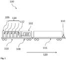
- Fig. 1 shows the modular system 100 for weed control for a rail vehicle in a schematic representation.
- the modular system has a control unit 104, which is contained in a control and monitoring module 102, a herbicide and mixing module 106, a nozzle assembly 108 and a camera module 110.
- the control unit 104 is configured to generate a first set of control signals for controlling valves and mixers 112 in the separate herbicide and mixing module 106 for mixing a herbicide mixture, and for generating a second set of control signals for controlling valves of a nozzle assembly 108.
- the herbicide and mixing module 106 has containers 114 for receiving different herbicides, which are selectively fluidly connected to the valves and mixers 112, and connection elements - for example plugs on an outer wall - via which electrical signal connections to connection elements - for example plugs an outer wall - of the control unit 104, so that the first control signals generated by the control unit 104 in the control and monitoring module 102 can be routed to the valves and mixers 112 of the herbicide and mixing module 106.
- the nozzle assembly 108 which is spatially independent of both the control and monitoring module 102 and the herbicide and mixing module 106, has a first set of nozzles for spraying herbicides and at least one fluid connection to selected ones of the valves and mixers 112 of the herbicide and mixing module 106.
- the camera module 110 which generates a weed signal in response to a detection of a weed, can be connected to a preceding carriage 116 with respect to a carrying carriage 118, which includes the control unit 104 in the control and monitoring module 102, the herbicide and mixing module 106 and the nozzle assembly 108 carries, be attached.
- the camera module 110 can have a plurality of individual cameras which are directed in the direction of travel 120 onto the track bed (not shown) in front of them.
- the generation of the first set of control signals and the generation of the second set of control signals by the weed signal can be controlled by means of the control unit.
- the camera module 110 has a predefined distance from the nozzle assembly 108.
- the camera module 110 is also spatially separated from the control and monitoring module 102 and the herbicide and mixing module 106 in a common direction of movement of the control and monitoring module 102, the herbicide and mixing module 106 and the nozzle assembly 108. This means that it is not mounted on the carriage 118 that carries the control unit 104 and the nozzle assembly 108. Rather, it is reversibly fixed at a position in the direction of travel 120, so that for the image evaluation of the Camera module 110 and the provision of the corresponding herbicide mixtures at the nozzle assembly 108, even at higher speeds, sufficient time is available.
- the car 116 traveling in front can be, for example, a tank car from which mixed water can be made available for the herbicide and mixing module 106 via a hose connection.
- one or more other cars or a locomotive can also be arranged between the nozzle assembly 108 and the camera module 110.
- the camera module 110 can also be fixed to a train traveling ahead with a known distance or a drone flying ahead.
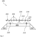
- FIG. 2 shows a nozzle assembly 202 with a plurality of nozzles 204 over a track bed 206 and side embankments 208.
- FIG Fig. 2 the rail tracks 210, 212 shown on the track bed 206.
- nozzle 216 it is shown by broken lines how, for example, a full jet nozzle can spray a herbicide mixture onto the track bed 206.
- the function of a half-jet nozzle is shown using the example of the right outer nozzle 218.
- the right area of the nozzle jet is limited here so that the rail 212 cannot be sprayed.
- nozzles that are located outside of the respective rail tracks 210, 212 - shown by way of example using the nozzles 220 - can be used for spraying the respective embankment (here embankment 208) and also a path that runs parallel to embankment 208.
- That nozzle of the nozzles 220 that is closest to the rail 212 is again designed as a half-jet nozzle so that the rail 212 is not sprayed. The same applies to the left side of the nozzle assembly 202.
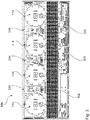
- Fig. 3 shows an embodiment of the herbicide and mixing module 106 in a plan view with the roof removed.
- a catwalk 302 connects a left input side with a right input side of the herbicide and mixing module 106.
- a multiplicity of lines, valves and mixers 304 as well as pumps 306 (as an example) and other other control devices (not shown in detail) enable a mixture of various herbicide mixtures, for example weed-specific herbicide mixtures.
- the herbicide and mixing module 106 is typically located in a housing in the form of a 20-foot standard container in accordance with ISO 668: 2013-08.
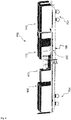
- Fig. 4 shows an exemplary embodiment of a plan view of the energy module 400.
- the energy module 400 consists of an actual energy generation block 404, in which an internal combustion engine can generate electricity with the aid of a generator. Via an operating terminal 406, the energy generation block 404 can be controlled from the outside. A tank for the fuel can be filled from above.
- the power generation block 404 is mounted on a platform that can take up the footprint of a standard 20 foot container, for example. On this energy module 400 one can also see fastening points 402 for fastening to a carrying car. A lateral grille 414 protects the operating personnel from falling down from the platform 408.
- the platform 408 can be reached via a respective ladder 410. This can be locked by respective pivoting doors 412. There is no need to provide a grid on the respective left and right side of the energy module 400. Rather, the other modules - the control and monitoring module and the herbicide and mixing module - can be reached via these ends of the energy module 400.
- Fig. 5 shows several modules in context. On the far left is the herbicide and mixing module 106, followed by the energy module 400, the control and monitoring module 102 with the control unit 104 (not shown) and an additional residence module 502 Buffers 504 can be seen that all modules are shown next to each other on a carrier car.
- Fig. 6 shows an example of a perspective view 600 of the multiple modules: the herbicide and mixing module 106, the energy module 400, the control and monitoring module 102 and the stay module 502. All modules are shown on a carriage 602 with two double-axle turnstiles 604 . The sequence shown for the individual modules has proven to be advantageous.
- the stay module 502 is located furthest away from the herbicide and mixing module 106, so that even in the event of a malfunction of the herbicide and mixing module 106 (for example uncontrolled herbicide leakage), the personnel on board are protected solely by the distance .
- the nozzle assembly 108 can be seen schematically below the control and plugging module 102 on the carrying car.
- the energy module 400 is located between the herbicide and mixing module 106 and the control and monitoring module 102 and can easily supply both modules with energy.
- the platform of the energy module 400 is easily accessible both from the herbicide and mixing module 106 and from the control and monitoring module 104.
- Fig. 7 shows an example of a perspective view of a train 700 consisting of a storage wagon 702, the carrying wagon 704 with the complete modular system for weed control and a tank wagon 706 with which water can be transported, which is made available to the herbicide and mixing module 106 via hoses can be.
- the camera module 110 is shown in the front area of the tank car 706.
- the energy module 400 can be identified with its platform.
- the supply cart 702 can be used to store and transport various supplies for the train 700; in particular, various herbicides can be stored directly and in larger quantities in this way.
- the supply of herbicides is therefore not limited to the capacity of the containers in the herbicide and mixing module 106.
- a locomotive can be provided at the beginning or at the end of the train 700.
- the orientation - i.e. the exit of the herbicides from the nozzle assembly - has to be adjusted according to the direction of travel of the train. It is not necessary to rearrange the modules of the modular system for weed control for a different direction of travel.
- FIG. 8th shows the method 800 for combating weeds in a track bed.
- the method 800 comprises a reversible fixing 802 of a control unit in a control and monitoring module on a carrying wagon, a reversible fixing 804 of a herbicide and mixing module (HMM) on the carrying wagon , and a reversible fixing 806 of a nozzle assembly on the carriage.
- the nozzle assembly is spatially independent of both the control and monitoring module and the herbicide and mixing module.
- the method 800 includes establishing 808 a fluid connection between the herbicide and mixing module and the nozzle assembly and generating 810 a weed signal by means of a camera module.
- the camera module is arranged at a distance in front of the carrier car in one direction of travel of the carrier car.
- the method 800 comprises influencing 812 a first set of control signals for controlling valves and mixers in the herbicide and mixing module for mixing a herbicide mixture by means of the control unit as a function of the weed signal from the camera module and influencing 814 a second set of control signals for Controlling valves of a nozzle assembly by means of the control unit depending on the weed signal of the camera module.
- the method 800 comprises a selective spraying 816 of the herbicide mixture via nozzles of the nozzle assembly onto the railways.
Landscapes
- Engineering & Computer Science (AREA)
- Architecture (AREA)
- Civil Engineering (AREA)
- Structural Engineering (AREA)
- Transportation (AREA)
- Mechanical Engineering (AREA)
- Chemical & Material Sciences (AREA)
- Analytical Chemistry (AREA)
- Catching Or Destruction (AREA)
- Soil Working Implements (AREA)
- Agricultural Chemicals And Associated Chemicals (AREA)
- Special Spraying Apparatus (AREA)
- Spray Control Apparatus (AREA)
Claims (12)
- Train de pulvérisation pour la lutte contre les mauvaises herbes sur des voies ferrées, comprenant au moins deux wagons porteurs ou au moins un wagon porteur et un objet volant téléguidé, ainsi qu'un système modulaire (100) pour un véhicule ferroviaire pour la lutte contre les mauvaises herbes, comprenant- un module de commande et de contrôle (102),- un module de mélange d'herbicide (106),- un porte-diffuseur (108), et- un module de caméra (110) ;le module de commande et de contrôle (102), le module de mélange d'herbicide (106) et le porte-diffuseur (108) pouvant respectivement être fixés de manière individuellement réversible à un élément de support ;
le module de commande et de contrôle (102) comprenant une unité de commande (104),
dans lequel l'unité de commande (104) est aménagée- pour générer un premier ensemble de signaux de commande pour commander des vannes et des mélangeurs (112) dans le module de mélange d'herbicide (106) pour préparer un mélange d'herbicide, et- pour générer un deuxième ensemble de signaux de commande pour commander des vannes du porte-diffuseur (108) ;le module de mélange d'herbicide (106) comprenant :- des vannes et des mélangeurs (112),- des conteneurs (114) pour recevoir différents herbicides qui sont sélectivement en communication fluidique sélective avec les vannes et les mélangeurs (112),- des éléments de connexion permettant d'établir des liaisons de signal électriques avec des éléments de connexion de l'unité de commande (104) de sorte que les premiers signaux de commande générés dans l'unité de commande (104) peuvent être guidés aux vannes et aux mélangeurs (112) du module de mélange d'herbicide (106) ; le module de caméra (110)- présentant une distance prédéfinie par rapport au porte-diffuseur (108),- présentant une distance prédéfinie par rapport à l'unité de commande (104),- étant séparé physiquement de l'unité de commande (104), du module de mélange d'herbicide (106) et du porte-diffuseur (108) respectivement,- étant disposé avant l'unité de commande (104), le module de mélange d'herbicide (106) et le porte-diffuseur (108) dans une direction de déplacement commune, et- étant aménagé pour générer un signal de mauvaise herbe en réponse à une reconnaissance d'une mauvaise herbe ;et
la génération du premier ensemble de signaux de commande et la génération du deuxième ensemble de signaux de commande pouvant être commandées par le signal de mauvaise herbe du module de caméra (110) au moyen de l'unité de commande (104),
caractérisé en ce que le module de caméra (110) est fixé de manière réversible à un wagon précédant l'unité de commande (104) parmi les au moins deux wagons porteurs, ou en ce que le module de caméra (110) est fixé à l'objet volant téléguidé. - Train de pulvérisation selon la revendication 1, dans lequel l'élément de support est un wagon porteur pour une utilisation sur rails.
- Train de pulvérisation selon l'une quelconque des revendications précédentes, dans lequel le module de caméra (110) est adapté pour générer un signal de mauvaise herbe spécifique à une mauvaise herbe,
et dans lequel l'unité de commande (104) est adaptée pour recevoir le signal de mauvaise herbe spécifique à une mauvaise herbe provenant du module de caméra (110), et l'unité de commande (104) est adaptée pour générer, lors de la génération du premier ensemble de signaux de commande, des signaux de mauvaise herbe spécifiques à une mauvaise herbe pour commander les vannes et les mélangeurs (112) dans le module de mélange d'herbicide (106) afin de préparer un mélange d'herbicide spécifique à une mauvaise herbe. - Train de pulvérisation selon l'une quelconque des revendications précédentes, dans lequel le porte-diffuseur (108) présente un groupe de buses pour rail intermédiaire et deux groupes de buses pour talus.
- Train de pulvérisation selon la revendication 4, dans lequel les buses pour rail intermédiaire du groupe des buses pour rail intermédiaire qui sont les plus proches de sections de rail situées en oblique sous celles-ci sont des buses à demi-jet et les autres buses pour rail intermédiaire sont des buses à jet plein.
- Train de pulvérisation selon la revendication 4 ou 5, dans lequel les buses pour talus des deux groupes de buses pour talus qui sont les plus proches des sections de rail situées en oblique sous celles-ci sont des buses à demi-jet et les autres buses pour rail intermédiaire sont des buses à jet plein.
- Train de pulvérisation selon l'une quelconque des revendications précédentes, dans lequel les buses du porte-diffuseur (108) sont des buses à cuillère, et dans lequel la sortie du jet de pulvérisation est formée par une sortie d'air comprimé située en cercle autour d'une ouverture de sortie pour le mélange d'herbicide.
- Train de pulvérisation selon l'une quelconque des revendications précédentes, dans lequel le porte-diffuseur (108) est fixé à l'élément de support au-dessous du module de commande et de contrôle (102).
- Train de pulvérisation selon l'une quelconque des revendications 1 à 8, comprenant en outre- un module d'énergie (400), le module d'énergie (400) pouvant être relié électriquement au module de commande et de contrôle (102) et au module de mélange d'herbicide (106) respectivement, et le module d'énergie (400) pouvant être fixé de manière réversible à l'élément de support, et- un module de séjour (502) présentant un passage vers le module de commande et de contrôle (102), le module de séjour (502) pouvant être fixé de manière réversible à l'élément de support.
- Train de pulvérisation selon la revendication 9, caractérisé en ce que les modules sont disposés dans l'ordre suivant dans l'une des deux directions de déplacement possibles du train de pulvérisation : module de mélange d'herbicide (106), module d'énergie (400), module de commande et de contrôle (102), module de séjour (502) .
- Procédé de lutte contre les mauvaises herbes sur un ballast de voie, comprenant les étapes suivantes :- la fixation réversible d'un module de commande et de contrôle (102) comprenant une unité de commande (104) à un wagon porteur,- la fixation réversible d'un module de mélange d'herbicide (106) au wagon porteur,- la fixation réversible d'un porte-diffuseur (108) au wagon porteur, le porte-diffuseur (108) étant respectivement physiquement indépendant à la fois du module de commande et de contrôle (102) et du module de mélange d'herbicide (106),- l'établissement d'une communication fluidique entre le module de mélange d'herbicide (106) et le porte-diffuseur (108),- la génération d'un signal de mauvaise herbe au moyen d'un module de caméra (110) qui est disposé à distance avant le wagon porteur dans un sens de la marche du wagon porteur,- le fait d'influencer un premier ensemble de signaux de commande pour commander des vannes et des mélangeurs (112) dans le module de mélange d'herbicide (106) afin de préparer un mélange d'herbicide, au moyen de l'unité de commande (104) en fonction du signal de mauvaise herbe provenant du module de caméra (110),- le fait d'influencer un deuxième ensemble de signaux de commande pour commander des vannes d'un porte-diffuseur (108), au moyen de l'unité de commande (104), en fonction du signal de mauvaise herbe provenant du module de caméra (110), et- la pulvérisation sélective du mélange d'herbicide par des buses du porte-diffuseur (108) sur les voies ferrées,caractérisé en ce que le module de caméra (110) est fixé de manière réversible à un wagon précédant l'unité de commande (104), ou en ce que le module de caméra (110) est fixé à un objet volant téléguidé.
- Procédé selon la revendication 11, comprenant en outre l'étape suivante :- la préservation des rails lors de la pulvérisation sélective du mélange d'herbicide sur une voie ferrée.
Applications Claiming Priority (3)
| Application Number | Priority Date | Filing Date | Title |
|---|---|---|---|
| EP17168844.3A EP3396068B1 (fr) | 2017-04-28 | 2017-04-28 | Système modulaire destiné à la lutte contre les mauvaises herbes |
| EP17172539.3A EP3406801B1 (fr) | 2017-05-23 | 2017-05-23 | Système haute vitesse destiné à la lutte contre les mauvaises herbes |
| PCT/EP2018/060459 WO2018197480A1 (fr) | 2017-04-28 | 2018-04-24 | Système à grande vitesse de lutte contre les mauvaises herbes |
Publications (2)
| Publication Number | Publication Date |
|---|---|
| EP3615738A1 EP3615738A1 (fr) | 2020-03-04 |
| EP3615738B1 true EP3615738B1 (fr) | 2021-03-10 |
Family
ID=62116834
Family Applications (2)
| Application Number | Title | Priority Date | Filing Date |
|---|---|---|---|
| EP18722926.5A Active EP3615737B1 (fr) | 2017-04-28 | 2018-04-23 | Système modulaire destiné à la lutte contre les mauvaises herbes |
| EP18724478.5A Active EP3615738B1 (fr) | 2017-04-28 | 2018-04-24 | Système à haute vitesse destiné à la lutte contre les mauvaises herbes |
Family Applications Before (1)
| Application Number | Title | Priority Date | Filing Date |
|---|---|---|---|
| EP18722926.5A Active EP3615737B1 (fr) | 2017-04-28 | 2018-04-23 | Système modulaire destiné à la lutte contre les mauvaises herbes |
Country Status (14)
| Country | Link |
|---|---|
| US (4) | US11668061B2 (fr) |
| EP (2) | EP3615737B1 (fr) |
| JP (3) | JP7344798B2 (fr) |
| KR (2) | KR102603661B1 (fr) |
| CN (3) | CN110573676B (fr) |
| AU (2) | AU2018258975B2 (fr) |
| BR (3) | BR112019022421B1 (fr) |
| CA (2) | CA3061543A1 (fr) |
| HU (1) | HUE054274T2 (fr) |
| MX (3) | MX2019012719A (fr) |
| NZ (2) | NZ758306A (fr) |
| PL (1) | PL3615737T3 (fr) |
| WO (2) | WO2018197388A1 (fr) |
| ZA (2) | ZA201906408B (fr) |
Families Citing this family (7)
| Publication number | Priority date | Publication date | Assignee | Title |
|---|---|---|---|---|
| WO2018197388A1 (fr) * | 2017-04-28 | 2018-11-01 | Bayer Aktiengesellschaft | Système modulaire de lutte contre les mauvaises herbes |
| EP3403899A1 (fr) | 2017-05-17 | 2018-11-21 | Bayer Aktiengesellschaft | Lutte contre les mauvaises herbes à haute vitesse |
| EP3666622A1 (fr) * | 2018-12-14 | 2020-06-17 | Bilberry SAS | Système et procédé de désherbage pour un chemin de fer |
| CN110419521A (zh) * | 2019-09-04 | 2019-11-08 | 方大特钢科技股份有限公司 | 一种多功能轨道喷洒平台装置 |
| CN111903656A (zh) * | 2020-08-03 | 2020-11-10 | 界首市利能环保技术开发有限公司 | 一种基于铁路轨道的分散式药物喷洒装置 |
| KR102475380B1 (ko) * | 2020-09-14 | 2022-12-08 | 대한민국 | Gps 기반 지능형 방제 장치 및 그 동작 방법 |
| NL2026771B1 (nl) * | 2020-10-26 | 2022-09-16 | H Harinck Beheer B V | Toedienautomaat |
Family Cites Families (25)
| Publication number | Priority date | Publication date | Assignee | Title |
|---|---|---|---|---|
| US722494A (en) * | 1902-09-25 | 1903-03-10 | Gideon A Copp | Device for preventing train-robberies. |
| US3101902A (en) * | 1962-07-30 | 1963-08-27 | Chipman Chemical Company Ltd | Spraying apparatus |
| GB1404342A (en) | 1972-04-25 | 1975-08-28 | Chipman Chem Co | Spraying apparatus |
| JPS5178880U (fr) | 1974-12-13 | 1976-06-22 | ||
| JPS52170409U (fr) * | 1976-06-16 | 1977-12-24 | ||
| NL8800868A (nl) | 1988-04-05 | 1989-11-01 | Nl Spoorwegen Nv | Stelsel voor het besturen van de besproeiing van onkruid bij spoorlijnen. |
| DE4132637C2 (de) * | 1991-10-01 | 1995-04-27 | Walter Prof Dr Kuehbauch | Verfahren zur gesteuerten Unkrautbekämpfung |
| AT399523B (de) * | 1992-06-22 | 1995-05-26 | Wagner Elektrothermit | Vorrichtung zum vernichten von unerwünschtem pflanzenwuchs im bereich von fahrwegen |
| US5465874A (en) | 1993-11-17 | 1995-11-14 | Basf Corporation | Portable multi-compartment chemical storage and mixing tank |
| GB2315436B (en) * | 1996-07-24 | 2000-03-29 | Nomix Chipman Ltd | Distribution of a liquid composition |
| GB2327231A (en) * | 1997-07-11 | 1999-01-20 | Aqua Hydraulics Ltd | Vehicle with weed/foliage killing facility |
| HU224536B1 (hu) * | 2002-07-05 | 2005-10-28 | G & G Növényvédelmi és Kereskedelmi Kft. | Vasúti kocsira szerelt gyomirtó berendezés kapcsolási elrendezése, és eljárás a berendezéssel történõ gyomirtásra |
| JP4660169B2 (ja) * | 2004-11-19 | 2011-03-30 | 株式会社キクテック | レールの印字方法と装置 |
| EP1695620A1 (fr) * | 2005-02-28 | 2006-08-30 | Giovanni Grilli | Appareil de destruction des mauvaises herbes |
| CN100437629C (zh) * | 2005-10-08 | 2008-11-26 | 中国农业机械化科学研究院 | 一种自动识别田间杂草的方法 |
| US20080094935A1 (en) | 2006-10-23 | 2008-04-24 | Newton John R | Modular liquid injection mixing and delivery system |
| US7975621B2 (en) * | 2008-10-08 | 2011-07-12 | Gibson Don | Rail firefighting platform |
| CN101707992B (zh) * | 2009-10-15 | 2011-01-05 | 南京林业大学 | 高效除草机器人 |
| CZ305287B6 (cs) * | 2012-11-02 | 2015-07-15 | Jaro Česká Skalice, S.R.O. | Postřikové zařízení |
| CN203923989U (zh) * | 2014-05-27 | 2014-11-05 | 宣化钢铁集团有限责任公司 | 一种用于铁路站场的除草装置 |
| KR20160015640A (ko) * | 2014-07-31 | 2016-02-15 | 한온시스템 주식회사 | 차량용 전기집진장치 |
| CN104186451B (zh) * | 2014-08-19 | 2017-06-20 | 西北农林科技大学 | 一种基于机器视觉的除虫除草喷药机器人 |
| PL3358525T3 (pl) * | 2017-02-06 | 2021-07-05 | Bilberry Sas | Systemy i sposoby usuwania chwastów, pojazdy kolejowe do usuwania chwastów |
| WO2018197388A1 (fr) * | 2017-04-28 | 2018-11-01 | Bayer Aktiengesellschaft | Système modulaire de lutte contre les mauvaises herbes |
| DE102017004257A1 (de) * | 2017-05-04 | 2018-11-08 | Malte Höltken | Flächen- und/oder Körperbeaufschlagung zur Vegetationskontrolle |
-
2018
- 2018-04-23 WO PCT/EP2018/060293 patent/WO2018197388A1/fr not_active Ceased
- 2018-04-23 MX MX2019012719A patent/MX2019012719A/es unknown
- 2018-04-23 CA CA3061543A patent/CA3061543A1/fr active Pending
- 2018-04-23 BR BR112019022421-1A patent/BR112019022421B1/pt active IP Right Grant
- 2018-04-23 KR KR1020197031228A patent/KR102603661B1/ko active Active
- 2018-04-23 HU HUE18722926A patent/HUE054274T2/hu unknown
- 2018-04-23 CN CN201880027968.XA patent/CN110573676B/zh active Active
- 2018-04-23 JP JP2019558378A patent/JP7344798B2/ja active Active
- 2018-04-23 US US16/607,498 patent/US11668061B2/en active Active
- 2018-04-23 AU AU2018258975A patent/AU2018258975B2/en active Active
- 2018-04-23 EP EP18722926.5A patent/EP3615737B1/fr active Active
- 2018-04-23 BR BR122023002967-4A patent/BR122023002967B1/pt active IP Right Grant
- 2018-04-23 NZ NZ758306A patent/NZ758306A/en unknown
- 2018-04-23 PL PL18722926T patent/PL3615737T3/pl unknown
- 2018-04-24 WO PCT/EP2018/060459 patent/WO2018197480A1/fr not_active Ceased
- 2018-04-24 JP JP2019558616A patent/JP7127057B2/ja active Active
- 2018-04-24 NZ NZ758309A patent/NZ758309A/en unknown
- 2018-04-24 AU AU2018259017A patent/AU2018259017B2/en active Active
- 2018-04-24 US US16/607,620 patent/US11473256B2/en active Active
- 2018-04-24 CN CN201880027923.2A patent/CN110573675B/zh active Active
- 2018-04-24 EP EP18724478.5A patent/EP3615738B1/fr active Active
- 2018-04-24 BR BR112019022426-2A patent/BR112019022426B1/pt active IP Right Grant
- 2018-04-24 CA CA3061495A patent/CA3061495A1/fr active Pending
- 2018-04-24 KR KR1020197031230A patent/KR102637573B1/ko active Active
- 2018-04-24 CN CN202111622415.9A patent/CN114392851B/zh active Active
- 2018-04-24 MX MX2019012718A patent/MX2019012718A/es unknown
-
2019
- 2019-09-19 ZA ZA2019/06408A patent/ZA201906408B/en unknown
- 2019-09-25 ZA ZA2019/06307A patent/ZA201906307B/en unknown
- 2019-10-24 MX MX2023014517A patent/MX2023014517A/es unknown
-
2022
- 2022-09-12 US US17/931,392 patent/US12195936B2/en active Active
-
2023
- 2023-09-04 JP JP2023143075A patent/JP7556113B2/ja active Active
-
2024
- 2024-08-23 US US18/813,618 patent/US20240417943A1/en active Pending
Non-Patent Citations (1)
| Title |
|---|
| None * |
Also Published As
Similar Documents
| Publication | Publication Date | Title |
|---|---|---|
| EP3615738B1 (fr) | Système à haute vitesse destiné à la lutte contre les mauvaises herbes | |
| EP2242672B2 (fr) | Bloc de freinage modulaire | |
| DE2001334A1 (de) | Enteisungsvorrichtung insbesondere fuer Flugzeuge | |
| DE2842258A1 (de) | Verfahren und vorrichtung zur abgabe eines betriebsstoffes, insbesondere eines schmiermaterials | |
| WO2013030074A1 (fr) | Module de calcul de temps d'arrêt | |
| DE102015113177A1 (de) | Halte- und Wechselstation für Kabinenfahrzeuge eines schienengebundenen Personenverkehrssystems | |
| EP3406801B1 (fr) | Système haute vitesse destiné à la lutte contre les mauvaises herbes | |
| EP3396068B1 (fr) | Système modulaire destiné à la lutte contre les mauvaises herbes | |
| DE69402859T2 (de) | Transportvorrichtung und verfahren zum transportieren von containern | |
| DE102015113180A1 (de) | Kabinenfahrzeug für schienengebundenen Personenverkehr | |
| DE202015104196U1 (de) | Halte- und Wechselstation für Kabinenfahrzeuge eines schienengebundenen Personenverkehrssystems | |
| DE758203C (de) | Antriebseinrichtung fuer Schiffsaufschleppen | |
| DE29820833U1 (de) | Zug | |
| DE1405002A1 (de) | Fernstrassen-Entlastungsanlage | |
| DE202015104194U1 (de) | Kabinenfahrzeug für schienengebundenen Personenverkehr | |
| EP1051997B1 (fr) | Dispositif d'extinction d'incendie pour wagon ferroviaire | |
| EP2716815A2 (fr) | Véhicule de travail pour la pose de voies sur des tronçons de voie ferrée | |
| DE2302748A1 (de) | Einrichtung zum betrieb von schnellbahnen | |
| DE202015104195U1 (de) | Mehrschienengleis | |
| DE102015113178A1 (de) | Mehrschienengleis |
Legal Events
| Date | Code | Title | Description |
|---|---|---|---|
| STAA | Information on the status of an ep patent application or granted ep patent |
Free format text: STATUS: UNKNOWN |
|
| STAA | Information on the status of an ep patent application or granted ep patent |
Free format text: STATUS: THE INTERNATIONAL PUBLICATION HAS BEEN MADE |
|
| PUAI | Public reference made under article 153(3) epc to a published international application that has entered the european phase |
Free format text: ORIGINAL CODE: 0009012 |
|
| STAA | Information on the status of an ep patent application or granted ep patent |
Free format text: STATUS: REQUEST FOR EXAMINATION WAS MADE |
|
| 17P | Request for examination filed |
Effective date: 20191128 |
|
| AK | Designated contracting states |
Kind code of ref document: A1 Designated state(s): AL AT BE BG CH CY CZ DE DK EE ES FI FR GB GR HR HU IE IS IT LI LT LU LV MC MK MT NL NO PL PT RO RS SE SI SK SM TR |
|
| AX | Request for extension of the european patent |
Extension state: BA ME |
|
| DAV | Request for validation of the european patent (deleted) | ||
| DAX | Request for extension of the european patent (deleted) | ||
| GRAP | Despatch of communication of intention to grant a patent |
Free format text: ORIGINAL CODE: EPIDOSNIGR1 |
|
| STAA | Information on the status of an ep patent application or granted ep patent |
Free format text: STATUS: GRANT OF PATENT IS INTENDED |
|
| INTG | Intention to grant announced |
Effective date: 20201111 |
|
| GRAS | Grant fee paid |
Free format text: ORIGINAL CODE: EPIDOSNIGR3 |
|
| GRAA | (expected) grant |
Free format text: ORIGINAL CODE: 0009210 |
|
| STAA | Information on the status of an ep patent application or granted ep patent |
Free format text: STATUS: THE PATENT HAS BEEN GRANTED |
|
| AK | Designated contracting states |
Kind code of ref document: B1 Designated state(s): AL AT BE BG CH CY CZ DE DK EE ES FI FR GB GR HR HU IE IS IT LI LT LU LV MC MK MT NL NO PL PT RO RS SE SI SK SM TR |
|
| REG | Reference to a national code |
Ref country code: GB Ref legal event code: FG4D Free format text: NOT ENGLISH |
|
| REG | Reference to a national code |
Ref country code: AT Ref legal event code: REF Ref document number: 1369932 Country of ref document: AT Kind code of ref document: T Effective date: 20210315 Ref country code: CH Ref legal event code: EP |
|
| REG | Reference to a national code |
Ref country code: DE Ref legal event code: R096 Ref document number: 502018004288 Country of ref document: DE |
|
| REG | Reference to a national code |
Ref country code: IE Ref legal event code: FG4D Free format text: LANGUAGE OF EP DOCUMENT: GERMAN |
|
| REG | Reference to a national code |
Ref country code: LT Ref legal event code: MG9D |
|
| PG25 | Lapsed in a contracting state [announced via postgrant information from national office to epo] |
Ref country code: LT Free format text: LAPSE BECAUSE OF FAILURE TO SUBMIT A TRANSLATION OF THE DESCRIPTION OR TO PAY THE FEE WITHIN THE PRESCRIBED TIME-LIMIT Effective date: 20210310 Ref country code: NO Free format text: LAPSE BECAUSE OF FAILURE TO SUBMIT A TRANSLATION OF THE DESCRIPTION OR TO PAY THE FEE WITHIN THE PRESCRIBED TIME-LIMIT Effective date: 20210610 Ref country code: BG Free format text: LAPSE BECAUSE OF FAILURE TO SUBMIT A TRANSLATION OF THE DESCRIPTION OR TO PAY THE FEE WITHIN THE PRESCRIBED TIME-LIMIT Effective date: 20210610 Ref country code: HR Free format text: LAPSE BECAUSE OF FAILURE TO SUBMIT A TRANSLATION OF THE DESCRIPTION OR TO PAY THE FEE WITHIN THE PRESCRIBED TIME-LIMIT Effective date: 20210310 Ref country code: GR Free format text: LAPSE BECAUSE OF FAILURE TO SUBMIT A TRANSLATION OF THE DESCRIPTION OR TO PAY THE FEE WITHIN THE PRESCRIBED TIME-LIMIT Effective date: 20210611 Ref country code: FI Free format text: LAPSE BECAUSE OF FAILURE TO SUBMIT A TRANSLATION OF THE DESCRIPTION OR TO PAY THE FEE WITHIN THE PRESCRIBED TIME-LIMIT Effective date: 20210310 |
|
| REG | Reference to a national code |
Ref country code: NL Ref legal event code: MP Effective date: 20210310 |
|
| PG25 | Lapsed in a contracting state [announced via postgrant information from national office to epo] |
Ref country code: SE Free format text: LAPSE BECAUSE OF FAILURE TO SUBMIT A TRANSLATION OF THE DESCRIPTION OR TO PAY THE FEE WITHIN THE PRESCRIBED TIME-LIMIT Effective date: 20210310 Ref country code: LV Free format text: LAPSE BECAUSE OF FAILURE TO SUBMIT A TRANSLATION OF THE DESCRIPTION OR TO PAY THE FEE WITHIN THE PRESCRIBED TIME-LIMIT Effective date: 20210310 Ref country code: RS Free format text: LAPSE BECAUSE OF FAILURE TO SUBMIT A TRANSLATION OF THE DESCRIPTION OR TO PAY THE FEE WITHIN THE PRESCRIBED TIME-LIMIT Effective date: 20210310 |
|
| PG25 | Lapsed in a contracting state [announced via postgrant information from national office to epo] |
Ref country code: NL Free format text: LAPSE BECAUSE OF FAILURE TO SUBMIT A TRANSLATION OF THE DESCRIPTION OR TO PAY THE FEE WITHIN THE PRESCRIBED TIME-LIMIT Effective date: 20210310 |
|
| PG25 | Lapsed in a contracting state [announced via postgrant information from national office to epo] |
Ref country code: CZ Free format text: LAPSE BECAUSE OF FAILURE TO SUBMIT A TRANSLATION OF THE DESCRIPTION OR TO PAY THE FEE WITHIN THE PRESCRIBED TIME-LIMIT Effective date: 20210310 Ref country code: EE Free format text: LAPSE BECAUSE OF FAILURE TO SUBMIT A TRANSLATION OF THE DESCRIPTION OR TO PAY THE FEE WITHIN THE PRESCRIBED TIME-LIMIT Effective date: 20210310 Ref country code: SM Free format text: LAPSE BECAUSE OF FAILURE TO SUBMIT A TRANSLATION OF THE DESCRIPTION OR TO PAY THE FEE WITHIN THE PRESCRIBED TIME-LIMIT Effective date: 20210310 |
|
| PG25 | Lapsed in a contracting state [announced via postgrant information from national office to epo] |
Ref country code: IS Free format text: LAPSE BECAUSE OF FAILURE TO SUBMIT A TRANSLATION OF THE DESCRIPTION OR TO PAY THE FEE WITHIN THE PRESCRIBED TIME-LIMIT Effective date: 20210710 Ref country code: PL Free format text: LAPSE BECAUSE OF FAILURE TO SUBMIT A TRANSLATION OF THE DESCRIPTION OR TO PAY THE FEE WITHIN THE PRESCRIBED TIME-LIMIT Effective date: 20210310 Ref country code: SK Free format text: LAPSE BECAUSE OF FAILURE TO SUBMIT A TRANSLATION OF THE DESCRIPTION OR TO PAY THE FEE WITHIN THE PRESCRIBED TIME-LIMIT Effective date: 20210310 Ref country code: PT Free format text: LAPSE BECAUSE OF FAILURE TO SUBMIT A TRANSLATION OF THE DESCRIPTION OR TO PAY THE FEE WITHIN THE PRESCRIBED TIME-LIMIT Effective date: 20210712 Ref country code: RO Free format text: LAPSE BECAUSE OF FAILURE TO SUBMIT A TRANSLATION OF THE DESCRIPTION OR TO PAY THE FEE WITHIN THE PRESCRIBED TIME-LIMIT Effective date: 20210310 |
|
| REG | Reference to a national code |
Ref country code: DE Ref legal event code: R097 Ref document number: 502018004288 Country of ref document: DE |
|
| PG25 | Lapsed in a contracting state [announced via postgrant information from national office to epo] |
Ref country code: LU Free format text: LAPSE BECAUSE OF NON-PAYMENT OF DUE FEES Effective date: 20210424 |
|
| PLBE | No opposition filed within time limit |
Free format text: ORIGINAL CODE: 0009261 |
|
| STAA | Information on the status of an ep patent application or granted ep patent |
Free format text: STATUS: NO OPPOSITION FILED WITHIN TIME LIMIT |
|
| REG | Reference to a national code |
Ref country code: BE Ref legal event code: MM Effective date: 20210430 |
|
| PG25 | Lapsed in a contracting state [announced via postgrant information from national office to epo] |
Ref country code: DK Free format text: LAPSE BECAUSE OF FAILURE TO SUBMIT A TRANSLATION OF THE DESCRIPTION OR TO PAY THE FEE WITHIN THE PRESCRIBED TIME-LIMIT Effective date: 20210310 Ref country code: CH Free format text: LAPSE BECAUSE OF NON-PAYMENT OF DUE FEES Effective date: 20210430 Ref country code: AL Free format text: LAPSE BECAUSE OF FAILURE TO SUBMIT A TRANSLATION OF THE DESCRIPTION OR TO PAY THE FEE WITHIN THE PRESCRIBED TIME-LIMIT Effective date: 20210310 Ref country code: MC Free format text: LAPSE BECAUSE OF FAILURE TO SUBMIT A TRANSLATION OF THE DESCRIPTION OR TO PAY THE FEE WITHIN THE PRESCRIBED TIME-LIMIT Effective date: 20210310 Ref country code: LI Free format text: LAPSE BECAUSE OF NON-PAYMENT OF DUE FEES Effective date: 20210430 Ref country code: ES Free format text: LAPSE BECAUSE OF FAILURE TO SUBMIT A TRANSLATION OF THE DESCRIPTION OR TO PAY THE FEE WITHIN THE PRESCRIBED TIME-LIMIT Effective date: 20210310 |
|
| 26N | No opposition filed |
Effective date: 20211213 |
|
| PG25 | Lapsed in a contracting state [announced via postgrant information from national office to epo] |
Ref country code: SI Free format text: LAPSE BECAUSE OF FAILURE TO SUBMIT A TRANSLATION OF THE DESCRIPTION OR TO PAY THE FEE WITHIN THE PRESCRIBED TIME-LIMIT Effective date: 20210310 |
|
| PG25 | Lapsed in a contracting state [announced via postgrant information from national office to epo] |
Ref country code: IT Free format text: LAPSE BECAUSE OF FAILURE TO SUBMIT A TRANSLATION OF THE DESCRIPTION OR TO PAY THE FEE WITHIN THE PRESCRIBED TIME-LIMIT Effective date: 20210310 Ref country code: IE Free format text: LAPSE BECAUSE OF NON-PAYMENT OF DUE FEES Effective date: 20210424 |
|
| PG25 | Lapsed in a contracting state [announced via postgrant information from national office to epo] |
Ref country code: IS Free format text: LAPSE BECAUSE OF FAILURE TO SUBMIT A TRANSLATION OF THE DESCRIPTION OR TO PAY THE FEE WITHIN THE PRESCRIBED TIME-LIMIT Effective date: 20210710 |
|
| PG25 | Lapsed in a contracting state [announced via postgrant information from national office to epo] |
Ref country code: BE Free format text: LAPSE BECAUSE OF NON-PAYMENT OF DUE FEES Effective date: 20210430 |
|
| REG | Reference to a national code |
Ref country code: DE Ref legal event code: R081 Ref document number: 502018004288 Country of ref document: DE Owner name: DISCOVERY PURCHASER CORPORATION, WILMINGTON, US Free format text: FORMER OWNER: BAYER AKTIENGESELLSCHAFT, 51373 LEVERKUSEN, DE |
|
| P01 | Opt-out of the competence of the unified patent court (upc) registered |
Effective date: 20230421 |
|
| PG25 | Lapsed in a contracting state [announced via postgrant information from national office to epo] |
Ref country code: CY Free format text: LAPSE BECAUSE OF FAILURE TO SUBMIT A TRANSLATION OF THE DESCRIPTION OR TO PAY THE FEE WITHIN THE PRESCRIBED TIME-LIMIT Effective date: 20210310 |
|
| PG25 | Lapsed in a contracting state [announced via postgrant information from national office to epo] |
Ref country code: HU Free format text: LAPSE BECAUSE OF FAILURE TO SUBMIT A TRANSLATION OF THE DESCRIPTION OR TO PAY THE FEE WITHIN THE PRESCRIBED TIME-LIMIT; INVALID AB INITIO Effective date: 20180424 |
|
| REG | Reference to a national code |
Ref country code: GB Ref legal event code: 732E Free format text: REGISTERED BETWEEN 20230817 AND 20230823 |
|
| PG25 | Lapsed in a contracting state [announced via postgrant information from national office to epo] |
Ref country code: MK Free format text: LAPSE BECAUSE OF FAILURE TO SUBMIT A TRANSLATION OF THE DESCRIPTION OR TO PAY THE FEE WITHIN THE PRESCRIBED TIME-LIMIT Effective date: 20210310 |
|
| REG | Reference to a national code |
Ref country code: AT Ref legal event code: MM01 Ref document number: 1369932 Country of ref document: AT Kind code of ref document: T Effective date: 20230424 |
|
| PG25 | Lapsed in a contracting state [announced via postgrant information from national office to epo] |
Ref country code: AT Free format text: LAPSE BECAUSE OF NON-PAYMENT OF DUE FEES Effective date: 20230424 |
|
| PG25 | Lapsed in a contracting state [announced via postgrant information from national office to epo] |
Ref country code: AT Free format text: LAPSE BECAUSE OF NON-PAYMENT OF DUE FEES Effective date: 20230424 |
|
| PG25 | Lapsed in a contracting state [announced via postgrant information from national office to epo] |
Ref country code: MT Free format text: LAPSE BECAUSE OF FAILURE TO SUBMIT A TRANSLATION OF THE DESCRIPTION OR TO PAY THE FEE WITHIN THE PRESCRIBED TIME-LIMIT Effective date: 20210310 |
|
| PGFP | Annual fee paid to national office [announced via postgrant information from national office to epo] |
Ref country code: DE Payment date: 20250428 Year of fee payment: 8 |
|
| PGFP | Annual fee paid to national office [announced via postgrant information from national office to epo] |
Ref country code: GB Payment date: 20250422 Year of fee payment: 8 |
|
| PGFP | Annual fee paid to national office [announced via postgrant information from national office to epo] |
Ref country code: FR Payment date: 20250424 Year of fee payment: 8 |
|
| PG25 | Lapsed in a contracting state [announced via postgrant information from national office to epo] |
Ref country code: TR Free format text: LAPSE BECAUSE OF FAILURE TO SUBMIT A TRANSLATION OF THE DESCRIPTION OR TO PAY THE FEE WITHIN THE PRESCRIBED TIME-LIMIT Effective date: 20210310 |
|
| PGFP | Annual fee paid to national office [announced via postgrant information from national office to epo] |
Ref country code: AT Payment date: 20260410 Year of fee payment: 5 |