EP3616163B1 - Robotic systems and methods for operating a robot - Google Patents
Robotic systems and methods for operating a robot Download PDFInfo
- Publication number
- EP3616163B1 EP3616163B1 EP18718484.1A EP18718484A EP3616163B1 EP 3616163 B1 EP3616163 B1 EP 3616163B1 EP 18718484 A EP18718484 A EP 18718484A EP 3616163 B1 EP3616163 B1 EP 3616163B1
- Authority
- EP
- European Patent Office
- Prior art keywords
- point cloud
- cavities
- cavity
- robot
- cloud data
- Prior art date
- Legal status (The legal status is an assumption and is not a legal conclusion. Google has not performed a legal analysis and makes no representation as to the accuracy of the status listed.)
- Active
Links
Images
Classifications
-
- G—PHYSICS
- G06—COMPUTING OR CALCULATING; COUNTING
- G06T—IMAGE DATA PROCESSING OR GENERATION, IN GENERAL
- G06T7/00—Image analysis
- G06T7/70—Determining position or orientation of objects or cameras
-
- G—PHYSICS
- G06—COMPUTING OR CALCULATING; COUNTING
- G06T—IMAGE DATA PROCESSING OR GENERATION, IN GENERAL
- G06T7/00—Image analysis
- G06T7/0002—Inspection of images, e.g. flaw detection
-
- G—PHYSICS
- G06—COMPUTING OR CALCULATING; COUNTING
- G06T—IMAGE DATA PROCESSING OR GENERATION, IN GENERAL
- G06T2207/00—Indexing scheme for image analysis or image enhancement
- G06T2207/10—Image acquisition modality
- G06T2207/10028—Range image; Depth image; 3D point clouds
-
- G—PHYSICS
- G06—COMPUTING OR CALCULATING; COUNTING
- G06T—IMAGE DATA PROCESSING OR GENERATION, IN GENERAL
- G06T2207/00—Indexing scheme for image analysis or image enhancement
- G06T2207/20—Special algorithmic details
- G06T2207/20048—Transform domain processing
- G06T2207/20061—Hough transform
-
- G—PHYSICS
- G06—COMPUTING OR CALCULATING; COUNTING
- G06T—IMAGE DATA PROCESSING OR GENERATION, IN GENERAL
- G06T2207/00—Indexing scheme for image analysis or image enhancement
- G06T2207/20—Special algorithmic details
- G06T2207/20076—Probabilistic image processing
Definitions
- the present application generally relates to robots and more particularly, but not exclusively, to robotic systems and methods for operating a robot.
- Robotic systems and methods for operating a robot remain an area of interest.
- Some existing methods systems have various shortcomings, drawbacks and disadvantages relative to certain applications. For example, in some methods and systems, detecting features in a structure may be inefficient. Such systems are known from e.g. US 2017/0140539 A1 or WO 2016/189764 A1 . Accordingly, there remains a need for further contributions in this area of technology.
- One embodiment of the present invention is a unique method for operating a robot. Another embodiment is a unique robotic system. Other embodiments include apparatuses, systems, devices, hardware, methods, and combinations for robots and robotic vision. Further embodiments, forms, features, aspects, benefits, and advantages of the present application shall become apparent from the description and figures provided herewith.
- Some aspects of the present invention pertain to unsupervised multi-cavity detection in 3D scanning, e.g., for the automatic detection of cavities for robotic charging processes in mining walls (mine walls).
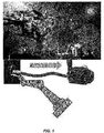
- the charging process in mining applications may include several steps: assembling the detonating cord with the detonator package; carrying the detonator package from a magazine holder to the cavity (a drilled hole in the mine wall) and inserting the detonator package into the cavity; and pumping explosive material into the cavity. If the charging process is to be performed by a robot, this requires a robust detection and identification of the cavities in order to accurately positioning the robot tooltip and locate the pump hose into the cavity.
- a 2D passive camera based cavity detection e.g., 2D visual servo control
- Such an approach would use a 2D video camera to generate or extract a 3D representation of the environment, specifically from the 2D video data.
- passive cameras such as a 2D video camera, typically require environments with constant illumination in order to detect the depth information, information that is used to accurately locate cavities in a 3D Euclidian space. Mining environments typically cannot provide such an environment.
- mining wall surfaces are typically irregular, making the automated detection of cavities difficult.
- some embodiments of the present invention employ one or more 3D sensors, such as RGB-D cameras, also called 3D cameras, to obtain a 3D point cloud data of the wall.
- 3D sensors such as RGB-D cameras, also called 3D cameras
- RGB-D cameras also called 3D cameras
- 3D sensors may be employed.
- the point cloud is then projected to topologically constrained canonical spaces. Multiple canonical spaces detect the depth difference and eliminate most of the irregularities, creating a set of cavity candidates that can be processed by image processing algorithms.
- Some embodiments of the present invention describe a method of how a 3D point cloud can be analyzed for its independent lower dimensions manifold representations in order to specifically identify the irregularities in the wall that represent the cavities, the surrounding irregularities in the rocks, and possibly also the variation in diameters in the cavities.
- the uncorrelated components of the point cloud are compared relative to the other uncorrelated components of the point cloud that belong to other canonical spaces, allowing an unsupervised detection of all the cavities present in the 3D point cloud.
- cavity detection is decoupled from the scanning source.
- a scalable solution is provided, i.e. processing time increases linearly to the size of the point cloud data, and specifically does not have proportionality to the number of cavities presented in the mining wall.
- some embodiments may reduce the overall detection time.
- cavity detection may be parallelized in some embodiments.
- the computational cost and time of detecting one cavity or N cavities in the point cloud that represents the entire wall may be reduced or minimized in some embodiments.
- some embodiments may improve the cavity detection robustness.
- statistical analysis of several canonical spaces may be employed to rank the cavity detection results.
- cavity detection is point cloud density agnostic - algorithms employed in some embodiments do not require highly accurate point cloud data in order to perform robust predictions of cavity locations.
- some embodiments may improve the cavity detection accuracy for robot positioning.
- some embodiments may make the robot pump hose insertion in charging applications faster, and in some embodiments, more reliable.
- some embodiments of the present invention describe a method for an unsupervised detection of cavities in uneven surfaces for robotic charging applications in mining.
- the method is a description of how a 3D point cloud can be analyzed for its independent lower dimensions manifold representations in order to identify the irregularities in the wall that are representing the cavities, the surrounding irregularities in the rocks, and possibly also the variation in diameters in the cavities.
- DR Dimensionality reduction
- point cloud data are obtained, e.g. by one or more 3D sensors.
- the point cloud belongs to a manifold M, embedded into a high-dimensional Euclidean space R M .
- the manifold M is assumed to have a low intrinsic dimension m (m ⁇ M), i.e., it has a parametrization in a subset C of R m , represented by the smooth bijective map ⁇ : C c R m ⁇ M .
- the geodesic distance ⁇ : M x M ⁇ R defined as the length of the shortest paths on M (called geodesics), represent the intrinsic structure of the data.
- 3D point cloud data of the wall has to be collected through the 3D sensor, where the density and quality of the point cloud are parameters and not a requirement.
- the point cloud data can be obtained by one or more 3D sensors
- the algorithm to detect N-cavities simultaneously is an unsupervised algorithm. Therefore there is no need of previous knowledge about the structure of the mining wall represented by the point cloud.
- the unsupervised multi-cavity detection from the 3D point cloud data may include one or more of the following steps in some embodiments:
- the first step is a topological constrained manifold analysis that aims to eliminate or is for eliminating irregularities by analyzing the data at its lower dimensionality.
- the second step is a lower dimensionality boundary detection that aims to label or is for labeling selected points as possible boundaries in a more controlled canonical space.
- the third step is a multi-cavity detection that analyses and scores the boundaries from the previous steps by applying image processing techniques.
- a more controlled canonical space can be understood as a canonical space in which it is easier to extract characteristics therefrom.
- the more controlled canonical space may be a 2D distribution or normalized space, may be accessible for mapping eigenvektors, and/or may be transferred by a Laplacian transformation.
- the goal of this step is, given M, to recover the parametrization in R m .
- the intrinsic dimension m is usually assumed to be known a priori.
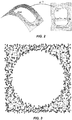
- the data samples are denoted by z i , i ⁇ I, a point on M, where / is a set of continuous indices. See FIG. 2 .
- the method may include one or more of the following steps:
- the obtained points x 1 ⁇ , ... , x N ⁇ are the desired representation of M in R m .
- Step 1 Topologically constrained Manifold Analysis for point cloud data
- Some embodiments include an approach that allows handling point cloud data manifolds of arbitrary topology and still provide for the detection and elimination of inconsistences. See FIG. 2 .
- boundary detection some embodiments employ a boundary detection method, e.g. based on studying the properties of the coordinates of nearest neighbors of each point, reconstructed from local distances using classical canonical space mapping.
- Step 2 Boundary detection in a lower dimensional manifold (See FIG. 3 ).
- the method of some embodiments assumes that the point and its two opposite neighbors are a part of a curve along the boundary. It then tries to find points that are placed outside of this boundary on both sides of it, violating the conjecture. (See FIG. 3 ).
- step 1 topological constrained manifold analysis
- step 2 boundary detection
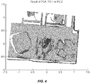
- the point cloud representation at the lower dimensional manifold with a label border is almost a noise free representation (See FIG. 4 ) that allows a more robust detection of cavities.
- the next task is the automatic data processing, with the major aim of detecting the cavities.
- Automatic methods may be employed to help to detect cavities now represented by empty circles in a 1d-manifold, region growing.
- the Hough-transform and Random Sample Consensus (RANSAC) paradigms may be employed.
- the method uses a combination of the Hough-transform and RANSAC.
- the Hough-transform may be very sensitive to the segmentation parameter values. Therefore, in some embodiments, the RANSAC algorithm is utilized, and is extended to exceed its limitations by the addition of the Hough-transform.
- this extension allows harmonizing the mathematical aspect of the algorithm with the geometry of a circle. This extended approach has provided very satisfactory results, even in the case of very weak point cloud density and for different levels of mining wall complexity.
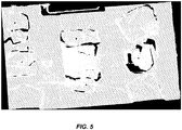
- FIG. 5 some aspects of a non-limiting example of several cavities and centroids being detected in accordance with an embodiment of the present invention are illustrated.
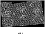
- FIG. 6 some aspects of a non-limiting example of multi-cavity detection, including simultaneous detection of cavities in a point cloud, in accordance with an embodiment of the present invention are illustrated.
- Embodiments of the present invention include a method for operating a robot, comprising: detecting a plurality of cavities in a structure, including: operating a 3D sensor to obtain 3D point cloud data of the structure; analyzing the 3D point cloud data at a lower dimensionality to eliminate irregularities; performing boundary detection of the 3D point cloud data at the lower dimensionality; and performing a multi-cavity detection of the 3D point cloud data to detect the plurality of cavities; directing the robot to a cavity of the plurality of cavities; and performing a robotic action on the cavity using the robot.
- the robot includes a robotic tool, further comprising engaging the cavity with the robotic tool.
- the method further comprises the robot pumping a material into the cavity.
- the structure is a mine wall; and the plurality of cavities are a plurality of drilled holes in the mine wall.
- the plurality of cavities are represented in the multi-cavity detection as empty circles in a 1D manifold.
- the boundary detection of the 3D point cloud data is performed based on the properties of coordinates of nearest neighbors of at least some points in the 3D point cloud.
- the multi-cavity detection is performed using both a Hough transform and random sample consensus (RANSAC).
- Embodiments of the present invention include a robotic system comprising: a robot; a 3D sensor; and a controller in communication with the sensor, wherein the controller is operative to detect a plurality of cavities in a structure, including: operating the 3D sensor to obtain 3D point cloud data of the structure; analyzing the 3D point cloud data at a lower dimensionality to eliminate irregularities; performing boundary detection of the 3D point cloud data at the lower dimensionality; and performing a multi-cavity detection of the 3D point cloud data to detect the plurality of cavities, wherein the robot is operative to perform a robotic operation on at least one cavity of the plurality of cavities.
- the robotic system may further include a network interface for connecting the device to a data network, in particular a global data network.
- the data network may be a TCP/IP network such as Internet.
- the robotic system may be operatively connected to the network interface for carrying out commands received from the data network.
- the commands may include a control command for controlling the device to carry out a task such as performing a robotic operation.
- the robotic system is adapted for carrying out the task in response to the control command.
- the commands may include a status request.
- the robotic system may be adapted for sending a status information to the network interface, and the network interface is then adapted for sending the status information over the network.
- the commands may include an update command including update data. In this case, the robotic system is adapted for initiating an update in response to the update command and using the update data.”
- the data network may be an Ethernet network using TCP/IP such as LAN, WAN or Internet.
- the data network may include distributed storage units such as Cloud.
- the Cloud can be in form of public, private, hybrid or community Cloud.
- the robotic system may further include a processing unit for converting the signal into a digital signal (or processing the signal).
- the robotic system may further include a network interface for connecting the robotic system to a network, wherein the network interface is configured to transceive digital signal/data between the robotic system and the data network, wherein the digital signal/data include operational command and/or information about the device or the network.
Landscapes
- Engineering & Computer Science (AREA)
- Computer Vision & Pattern Recognition (AREA)
- Physics & Mathematics (AREA)
- General Physics & Mathematics (AREA)
- Theoretical Computer Science (AREA)
- Quality & Reliability (AREA)
- Length Measuring Devices By Optical Means (AREA)
- Image Analysis (AREA)
- Manipulator (AREA)
Claims (8)
- Computerimplementiertes Verfahren zum Betreiben eines Roboters, umfassend
Detektieren von mehreren Hohlräumen in einer Struktur, einschließlich:Betreiben eines 3D-Sensors, um 3D-Punkt-Cloud-Daten der Struktur zu erhalten;Analysieren der 3D-Punkt-Cloud-Daten bei einer niedrigeren Dimensionalität, um Unregelmäßigkeiten zu eliminieren;Durchführen einer Grenzdetektion der 3D-Punkt-Cloud-Daten bei der niedrigeren Dimensionalität zum Bezeichnen selektierter Punkte als mögliche Grenzen; undDurchführen einer Mehrhohlraumdetektion der 3D-Punkt-Cloud-Daten bei der niedrigeren Dimensionalität, einschließlich Analysieren und Bepunkten der Grenzen, um die mehreren Hohlräume zu detektieren;Lenken des Roboters zu einem Hohlraum der mehreren Hohlräume; und
Durchführen einer Roboteroperation an dem Hohlraum unter Verwendung des Roboters. - Verfahren nach Anspruch 1, wobei der Roboter ein Roboterwerkzeug enthält, weiter umfassend das Ineingriffnehmen des Hohlraums mit dem Roboterwerkzeug.
- Verfahren nach Anspruch 2, weiter umfassend, dass der Roboter ein Material in den Hohlraum pumpt.
- Verfahren nach Anspruch 1, wobei die Struktur eine Minenwand ist und wobei die mehreren Hohlräume mehrere gebohrte Löcher in der Minenwand sind.
- Verfahren nach Anspruch 1, wobei die mehreren Hohlräume in der Mehrhohlraumdetektion als leere Kreise in einem 1D-Verteiler dargestellt werden.
- Verfahren nach Anspruch 1, wobei die Grenzdetektion der 3D-Punkt-Cloud-Daten auf Basis der Eigenschaften von Koordinaten von nächsten Nachbarn von mindestens einigen Punkten in der 3D-Punkt-Cloud durchgeführt wird.
- Verfahren nach Anspruch 1, wobei die Mehrhohlraumdetektion unter Verwendung einer Hough-Transformation und eines RANSCAC (Random Sample Consensus) durchgeführt wird.
- Robotersystem, umfassend:einen Roboter;einen 3D-Sensor; undeinen Controller in Kommunikation mit dem Sensor, wobei der Controller betreibbar ist zum Detektieren von mehreren Hohlräumen in einer Struktur, einschließlich:Betreiben eines 3D-Sensors, um 3D-Punkt-Cloud-Daten der Struktur zu erhalten;Analysieren der 3D-Punkt-Cloud-Daten bei einer niedrigeren Dimensionalität, um Unregelmäßigkeiten zu eliminieren;Durchführen einer Grenzdetektion der 3D-Punkt-Cloud-Daten bei der niedrigeren Dimensionalität zum Bezeichnen selektierter Punkte als mögliche Grenzen; undDurchführen einer Mehrhohlraumdetektion der 3D-Punkt-Cloud-Daten bei der niedrigeren Dimensionalität, einschließlich Analysieren und Bepunkten der Grenzen, um die mehreren Hohlräume zu detektieren;wobei der Roboter betreibbar ist zum Durchführen einer Roboteroperation an mindestens einem Hohlraum der mehreren Hohlräume.
Priority Applications (1)
| Application Number | Priority Date | Filing Date | Title |
|---|---|---|---|
| PL18718484T PL3616163T3 (pl) | 2017-04-26 | 2018-04-26 | Systemy zrobotyzowane i sposoby sterowania robotem |
Applications Claiming Priority (3)
| Application Number | Priority Date | Filing Date | Title |
|---|---|---|---|
| US201762490379P | 2017-04-26 | 2017-04-26 | |
| EP17186702.1A EP3444783A1 (de) | 2017-08-17 | 2017-08-17 | Robotersystem und verfahren zur steuerung |
| PCT/EP2018/060682 WO2018197601A1 (en) | 2017-04-26 | 2018-04-26 | Robotic systems and methods for operating a robot |
Publications (2)
| Publication Number | Publication Date |
|---|---|
| EP3616163A1 EP3616163A1 (de) | 2020-03-04 |
| EP3616163B1 true EP3616163B1 (de) | 2021-08-18 |
Family
ID=59811059
Family Applications (2)
| Application Number | Title | Priority Date | Filing Date |
|---|---|---|---|
| EP17186702.1A Withdrawn EP3444783A1 (de) | 2017-04-26 | 2017-08-17 | Robotersystem und verfahren zur steuerung |
| EP18718484.1A Active EP3616163B1 (de) | 2017-04-26 | 2018-04-26 | Robotic systems and methods for operating a robot |
Family Applications Before (1)
| Application Number | Title | Priority Date | Filing Date |
|---|---|---|---|
| EP17186702.1A Withdrawn EP3444783A1 (de) | 2017-04-26 | 2017-08-17 | Robotersystem und verfahren zur steuerung |
Country Status (7)
| Country | Link |
|---|---|
| EP (2) | EP3444783A1 (de) |
| CN (1) | CN110603571B (de) |
| AU (1) | AU2018259061B2 (de) |
| CA (1) | CA3061021A1 (de) |
| CL (1) | CL2019003048A1 (de) |
| PL (1) | PL3616163T3 (de) |
| WO (1) | WO2018197601A1 (de) |
Families Citing this family (2)
| Publication number | Priority date | Publication date | Assignee | Title |
|---|---|---|---|---|
| CA3234868A1 (en) * | 2018-08-09 | 2020-02-13 | Nokia Technologies Oy | Method and apparatus for security realization of connections over heterogeneous access networks |
| CN111210501B (zh) * | 2019-10-12 | 2021-06-18 | 香港理工大学深圳研究院 | 一种室内建模方法、装置及终端设备 |
Family Cites Families (9)
| Publication number | Priority date | Publication date | Assignee | Title |
|---|---|---|---|---|
| KR20110097140A (ko) * | 2010-02-24 | 2011-08-31 | 삼성전자주식회사 | 이동 로봇의 위치 추정 장치 및 방법 |
| US8380349B1 (en) * | 2011-05-06 | 2013-02-19 | Google Inc. | Methods and systems for providing instructions to a robotic device |
| EP2972478B1 (de) * | 2013-03-15 | 2020-12-16 | Uatc, Llc | Verfahren, systeme und vorrichtungen für eine multisensorische stereovision für robotersysteme |
| CN104616278B (zh) * | 2013-11-05 | 2020-03-17 | 北京三星通信技术研究有限公司 | 三维点云兴趣点检测方法和系统 |
| CN103612262B (zh) * | 2013-11-08 | 2015-08-26 | 邹建军 | 一种热室环境下靶体遥控自动维护装置及其维护方法 |
| US9233469B2 (en) * | 2014-02-13 | 2016-01-12 | GM Global Technology Operations LLC | Robotic system with 3D box location functionality |
| CN104568983B (zh) * | 2015-01-06 | 2017-03-15 | 浙江工业大学 | 基于主动式全景视觉的管道内部缺陷检测装置及方法 |
| US10046459B2 (en) * | 2015-11-16 | 2018-08-14 | Abb Schweiz Ag | Three-dimensional visual servoing for robot positioning |
| CN105598965B (zh) * | 2015-11-26 | 2018-03-16 | 哈尔滨工业大学 | 基于立体视觉的机器人欠驱动手自主抓取方法 |
-
2017
- 2017-08-17 EP EP17186702.1A patent/EP3444783A1/de not_active Withdrawn
-
2018
- 2018-04-26 AU AU2018259061A patent/AU2018259061B2/en active Active
- 2018-04-26 CA CA3061021A patent/CA3061021A1/en active Pending
- 2018-04-26 CN CN201880028000.9A patent/CN110603571B/zh active Active
- 2018-04-26 PL PL18718484T patent/PL3616163T3/pl unknown
- 2018-04-26 WO PCT/EP2018/060682 patent/WO2018197601A1/en not_active Ceased
- 2018-04-26 EP EP18718484.1A patent/EP3616163B1/de active Active
-
2019
- 2019-10-24 CL CL2019003048A patent/CL2019003048A1/es unknown
Also Published As
| Publication number | Publication date |
|---|---|
| PL3616163T3 (pl) | 2022-01-17 |
| AU2018259061A1 (en) | 2019-11-14 |
| EP3616163A1 (de) | 2020-03-04 |
| EP3444783A1 (de) | 2019-02-20 |
| CA3061021A1 (en) | 2018-11-01 |
| CN110603571B (zh) | 2023-11-03 |
| CL2019003048A1 (es) | 2020-05-04 |
| CN110603571A (zh) | 2019-12-20 |
| AU2018259061B2 (en) | 2020-10-22 |
| WO2018197601A1 (en) | 2018-11-01 |
Similar Documents
| Publication | Publication Date | Title |
|---|---|---|
| CN110807350A (zh) | 用于面向扫描匹配的视觉slam的系统和方法 | |
| EP3159121A1 (de) | Vorrichtung zur aktualisierung der karte eines mobilen roboters und verfahren dafür | |
| EP2495632A1 (de) | Kartenerstellungs- und aktualisierungsverfahren für positionserkennung bei einem mobilen roboter | |
| CN111489393A (zh) | Vslam方法、控制器和可移动设备 | |
| Della Corte et al. | Unified motion-based calibration of mobile multi-sensor platforms with time delay estimation | |
| EP3159126A1 (de) | Vorrichtung und verfahren zur detektion des standorts eines mobilen roboters mittels kantenbasierter nachjustierung | |
| Indelman et al. | Incremental distributed inference from arbitrary poses and unknown data association: Using collaborating robots to establish a common reference | |
| CN111784737A (zh) | 一种基于无人机平台的目标自动跟踪方法及系统 | |
| CN118962716A (zh) | 全景视觉与激光雷达融合的语义slam优化方法 | |
| Guerra et al. | UAV visual and laser sensors fusion for detection and positioning in industrial applications | |
| KR101460313B1 (ko) | 시각 특징과 기하 정보를 이용한 로봇의 위치 추정 장치 및 방법 | |
| EP3616163B1 (de) | Robotic systems and methods for operating a robot | |
| CN111563916B (zh) | 基于立体视觉的长时无人机跟踪定位方法、系统、装置 | |
| CN110598771A (zh) | 一种基于深度语义分割网络的视觉目标识别方法和装置 | |
| US12001218B2 (en) | Mobile robot device for correcting position by fusing image sensor and plurality of geomagnetic sensors, and control method | |
| CN109544632B (zh) | 一种基于层次主题模型的语义slam对象关联方法 | |
| CN113744301B (zh) | 移动机器人的运动轨迹估计方法、装置和存储介质 | |
| Koch et al. | Ground robot navigation using uncalibrated cameras | |
| Guerra et al. | Detection and positioning of pipes and columns with autonomous multicopter drones | |
| CN117576427A (zh) | 一种多目标匹配定位方法及装置 | |
| US20200334519A1 (en) | Learning View-Invariant Local Patch Representations for Pose Estimation | |
| Le Barz et al. | Absolute geo-localization thanks to Hidden Markov Model and exemplar-based metric learning | |
| Guerra et al. | Validation of data association for monocular SLAM | |
| CN116295425A (zh) | 一种定位信息确定装置、车辆、方法及程序产品 | |
| Hodges et al. | Multistage bayesian autonomy for high‐precision operation in a large field |
Legal Events
| Date | Code | Title | Description |
|---|---|---|---|
| STAA | Information on the status of an ep patent application or granted ep patent |
Free format text: STATUS: UNKNOWN |
|
| STAA | Information on the status of an ep patent application or granted ep patent |
Free format text: STATUS: THE INTERNATIONAL PUBLICATION HAS BEEN MADE |
|
| PUAI | Public reference made under article 153(3) epc to a published international application that has entered the european phase |
Free format text: ORIGINAL CODE: 0009012 |
|
| STAA | Information on the status of an ep patent application or granted ep patent |
Free format text: STATUS: REQUEST FOR EXAMINATION WAS MADE |
|
| 17P | Request for examination filed |
Effective date: 20191017 |
|
| AK | Designated contracting states |
Kind code of ref document: A1 Designated state(s): AL AT BE BG CH CY CZ DE DK EE ES FI FR GB GR HR HU IE IS IT LI LT LU LV MC MK MT NL NO PL PT RO RS SE SI SK SM TR |
|
| AX | Request for extension of the european patent |
Extension state: BA ME |
|
| DAV | Request for validation of the european patent (deleted) | ||
| DAX | Request for extension of the european patent (deleted) | ||
| GRAP | Despatch of communication of intention to grant a patent |
Free format text: ORIGINAL CODE: EPIDOSNIGR1 |
|
| STAA | Information on the status of an ep patent application or granted ep patent |
Free format text: STATUS: GRANT OF PATENT IS INTENDED |
|
| INTG | Intention to grant announced |
Effective date: 20210312 |
|
| GRAS | Grant fee paid |
Free format text: ORIGINAL CODE: EPIDOSNIGR3 |
|
| GRAA | (expected) grant |
Free format text: ORIGINAL CODE: 0009210 |
|
| STAA | Information on the status of an ep patent application or granted ep patent |
Free format text: STATUS: THE PATENT HAS BEEN GRANTED |
|
| RAP3 | Party data changed (applicant data changed or rights of an application transferred) |
Owner name: ABB SCHWEIZ AG |
|
| RIN1 | Information on inventor provided before grant (corrected) |
Inventor name: MARTINEZ, CARLOS Inventor name: ZHANG, BIAO Inventor name: MORATO, CARLOS |
|
| AK | Designated contracting states |
Kind code of ref document: B1 Designated state(s): AL AT BE BG CH CY CZ DE DK EE ES FI FR GB GR HR HU IE IS IT LI LT LU LV MC MK MT NL NO PL PT RO RS SE SI SK SM TR |
|
| REG | Reference to a national code |
Ref country code: GB Ref legal event code: FG4D |
|
| REG | Reference to a national code |
Ref country code: CH Ref legal event code: EP |
|
| REG | Reference to a national code |
Ref country code: DE Ref legal event code: R096 Ref document number: 602018022023 Country of ref document: DE |
|
| REG | Reference to a national code |
Ref country code: IE Ref legal event code: FG4D Ref country code: AT Ref legal event code: REF Ref document number: 1422318 Country of ref document: AT Kind code of ref document: T Effective date: 20210915 |
|
| REG | Reference to a national code |
Ref country code: FI Ref legal event code: FGE |
|
| REG | Reference to a national code |
Ref country code: SE Ref legal event code: TRGR |
|
| REG | Reference to a national code |
Ref country code: LT Ref legal event code: MG9D |
|
| REG | Reference to a national code |
Ref country code: NL Ref legal event code: MP Effective date: 20210818 |
|
| REG | Reference to a national code |
Ref country code: AT Ref legal event code: MK05 Ref document number: 1422318 Country of ref document: AT Kind code of ref document: T Effective date: 20210818 |
|
| PG25 | Lapsed in a contracting state [announced via postgrant information from national office to epo] |
Ref country code: LT Free format text: LAPSE BECAUSE OF FAILURE TO SUBMIT A TRANSLATION OF THE DESCRIPTION OR TO PAY THE FEE WITHIN THE PRESCRIBED TIME-LIMIT Effective date: 20210818 Ref country code: BG Free format text: LAPSE BECAUSE OF FAILURE TO SUBMIT A TRANSLATION OF THE DESCRIPTION OR TO PAY THE FEE WITHIN THE PRESCRIBED TIME-LIMIT Effective date: 20211118 Ref country code: AT Free format text: LAPSE BECAUSE OF FAILURE TO SUBMIT A TRANSLATION OF THE DESCRIPTION OR TO PAY THE FEE WITHIN THE PRESCRIBED TIME-LIMIT Effective date: 20210818 Ref country code: PT Free format text: LAPSE BECAUSE OF FAILURE TO SUBMIT A TRANSLATION OF THE DESCRIPTION OR TO PAY THE FEE WITHIN THE PRESCRIBED TIME-LIMIT Effective date: 20211220 Ref country code: NO Free format text: LAPSE BECAUSE OF FAILURE TO SUBMIT A TRANSLATION OF THE DESCRIPTION OR TO PAY THE FEE WITHIN THE PRESCRIBED TIME-LIMIT Effective date: 20211118 Ref country code: HR Free format text: LAPSE BECAUSE OF FAILURE TO SUBMIT A TRANSLATION OF THE DESCRIPTION OR TO PAY THE FEE WITHIN THE PRESCRIBED TIME-LIMIT Effective date: 20210818 Ref country code: ES Free format text: LAPSE BECAUSE OF FAILURE TO SUBMIT A TRANSLATION OF THE DESCRIPTION OR TO PAY THE FEE WITHIN THE PRESCRIBED TIME-LIMIT Effective date: 20210818 Ref country code: RS Free format text: LAPSE BECAUSE OF FAILURE TO SUBMIT A TRANSLATION OF THE DESCRIPTION OR TO PAY THE FEE WITHIN THE PRESCRIBED TIME-LIMIT Effective date: 20210818 |
|
| PG25 | Lapsed in a contracting state [announced via postgrant information from national office to epo] |
Ref country code: LV Free format text: LAPSE BECAUSE OF FAILURE TO SUBMIT A TRANSLATION OF THE DESCRIPTION OR TO PAY THE FEE WITHIN THE PRESCRIBED TIME-LIMIT Effective date: 20210818 Ref country code: GR Free format text: LAPSE BECAUSE OF FAILURE TO SUBMIT A TRANSLATION OF THE DESCRIPTION OR TO PAY THE FEE WITHIN THE PRESCRIBED TIME-LIMIT Effective date: 20211119 |
|
| PG25 | Lapsed in a contracting state [announced via postgrant information from national office to epo] |
Ref country code: NL Free format text: LAPSE BECAUSE OF FAILURE TO SUBMIT A TRANSLATION OF THE DESCRIPTION OR TO PAY THE FEE WITHIN THE PRESCRIBED TIME-LIMIT Effective date: 20210818 |
|
| PG25 | Lapsed in a contracting state [announced via postgrant information from national office to epo] |
Ref country code: DK Free format text: LAPSE BECAUSE OF FAILURE TO SUBMIT A TRANSLATION OF THE DESCRIPTION OR TO PAY THE FEE WITHIN THE PRESCRIBED TIME-LIMIT Effective date: 20210818 |
|
| REG | Reference to a national code |
Ref country code: DE Ref legal event code: R097 Ref document number: 602018022023 Country of ref document: DE |
|
| PG25 | Lapsed in a contracting state [announced via postgrant information from national office to epo] |
Ref country code: SM Free format text: LAPSE BECAUSE OF FAILURE TO SUBMIT A TRANSLATION OF THE DESCRIPTION OR TO PAY THE FEE WITHIN THE PRESCRIBED TIME-LIMIT Effective date: 20210818 Ref country code: SK Free format text: LAPSE BECAUSE OF FAILURE TO SUBMIT A TRANSLATION OF THE DESCRIPTION OR TO PAY THE FEE WITHIN THE PRESCRIBED TIME-LIMIT Effective date: 20210818 Ref country code: RO Free format text: LAPSE BECAUSE OF FAILURE TO SUBMIT A TRANSLATION OF THE DESCRIPTION OR TO PAY THE FEE WITHIN THE PRESCRIBED TIME-LIMIT Effective date: 20210818 Ref country code: EE Free format text: LAPSE BECAUSE OF FAILURE TO SUBMIT A TRANSLATION OF THE DESCRIPTION OR TO PAY THE FEE WITHIN THE PRESCRIBED TIME-LIMIT Effective date: 20210818 Ref country code: CZ Free format text: LAPSE BECAUSE OF FAILURE TO SUBMIT A TRANSLATION OF THE DESCRIPTION OR TO PAY THE FEE WITHIN THE PRESCRIBED TIME-LIMIT Effective date: 20210818 Ref country code: AL Free format text: LAPSE BECAUSE OF FAILURE TO SUBMIT A TRANSLATION OF THE DESCRIPTION OR TO PAY THE FEE WITHIN THE PRESCRIBED TIME-LIMIT Effective date: 20210818 |
|
| PLBE | No opposition filed within time limit |
Free format text: ORIGINAL CODE: 0009261 |
|
| STAA | Information on the status of an ep patent application or granted ep patent |
Free format text: STATUS: NO OPPOSITION FILED WITHIN TIME LIMIT |
|
| 26N | No opposition filed |
Effective date: 20220519 |
|
| PG25 | Lapsed in a contracting state [announced via postgrant information from national office to epo] |
Ref country code: IT Free format text: LAPSE BECAUSE OF FAILURE TO SUBMIT A TRANSLATION OF THE DESCRIPTION OR TO PAY THE FEE WITHIN THE PRESCRIBED TIME-LIMIT Effective date: 20210818 |
|
| PG25 | Lapsed in a contracting state [announced via postgrant information from national office to epo] |
Ref country code: SI Free format text: LAPSE BECAUSE OF FAILURE TO SUBMIT A TRANSLATION OF THE DESCRIPTION OR TO PAY THE FEE WITHIN THE PRESCRIBED TIME-LIMIT Effective date: 20210818 |
|
| REG | Reference to a national code |
Ref country code: CH Ref legal event code: PL |
|
| GBPC | Gb: european patent ceased through non-payment of renewal fee |
Effective date: 20220426 |
|
| REG | Reference to a national code |
Ref country code: BE Ref legal event code: MM Effective date: 20220430 |
|
| PG25 | Lapsed in a contracting state [announced via postgrant information from national office to epo] |
Ref country code: MC Free format text: LAPSE BECAUSE OF FAILURE TO SUBMIT A TRANSLATION OF THE DESCRIPTION OR TO PAY THE FEE WITHIN THE PRESCRIBED TIME-LIMIT Effective date: 20210818 Ref country code: LU Free format text: LAPSE BECAUSE OF NON-PAYMENT OF DUE FEES Effective date: 20220426 Ref country code: LI Free format text: LAPSE BECAUSE OF NON-PAYMENT OF DUE FEES Effective date: 20220430 Ref country code: GB Free format text: LAPSE BECAUSE OF NON-PAYMENT OF DUE FEES Effective date: 20220426 Ref country code: FR Free format text: LAPSE BECAUSE OF NON-PAYMENT OF DUE FEES Effective date: 20220430 Ref country code: CH Free format text: LAPSE BECAUSE OF NON-PAYMENT OF DUE FEES Effective date: 20220430 |
|
| PG25 | Lapsed in a contracting state [announced via postgrant information from national office to epo] |
Ref country code: BE Free format text: LAPSE BECAUSE OF NON-PAYMENT OF DUE FEES Effective date: 20220430 |
|
| PG25 | Lapsed in a contracting state [announced via postgrant information from national office to epo] |
Ref country code: MK Free format text: LAPSE BECAUSE OF FAILURE TO SUBMIT A TRANSLATION OF THE DESCRIPTION OR TO PAY THE FEE WITHIN THE PRESCRIBED TIME-LIMIT Effective date: 20210818 Ref country code: CY Free format text: LAPSE BECAUSE OF FAILURE TO SUBMIT A TRANSLATION OF THE DESCRIPTION OR TO PAY THE FEE WITHIN THE PRESCRIBED TIME-LIMIT Effective date: 20210818 |
|
| PG25 | Lapsed in a contracting state [announced via postgrant information from national office to epo] |
Ref country code: HU Free format text: LAPSE BECAUSE OF FAILURE TO SUBMIT A TRANSLATION OF THE DESCRIPTION OR TO PAY THE FEE WITHIN THE PRESCRIBED TIME-LIMIT; INVALID AB INITIO Effective date: 20180426 |
|
| PG25 | Lapsed in a contracting state [announced via postgrant information from national office to epo] |
Ref country code: MT Free format text: LAPSE BECAUSE OF FAILURE TO SUBMIT A TRANSLATION OF THE DESCRIPTION OR TO PAY THE FEE WITHIN THE PRESCRIBED TIME-LIMIT Effective date: 20210818 |
|
| PGFP | Annual fee paid to national office [announced via postgrant information from national office to epo] |
Ref country code: FI Payment date: 20250424 Year of fee payment: 8 |
|
| PGFP | Annual fee paid to national office [announced via postgrant information from national office to epo] |
Ref country code: DE Payment date: 20250422 Year of fee payment: 8 Ref country code: PL Payment date: 20250418 Year of fee payment: 8 |
|
| PGFP | Annual fee paid to national office [announced via postgrant information from national office to epo] |
Ref country code: TR Payment date: 20250421 Year of fee payment: 8 |
|
| PGFP | Annual fee paid to national office [announced via postgrant information from national office to epo] |
Ref country code: IE Payment date: 20250422 Year of fee payment: 8 |
|
| PGFP | Annual fee paid to national office [announced via postgrant information from national office to epo] |
Ref country code: SE Payment date: 20250429 Year of fee payment: 8 |