EP3616997B1 - Anordnung - Google Patents
Anordnung Download PDFInfo
- Publication number
- EP3616997B1 EP3616997B1 EP18192048.9A EP18192048A EP3616997B1 EP 3616997 B1 EP3616997 B1 EP 3616997B1 EP 18192048 A EP18192048 A EP 18192048A EP 3616997 B1 EP3616997 B1 EP 3616997B1
- Authority
- EP
- European Patent Office
- Prior art keywords
- post
- projection
- lever
- arrangement
- groove
- Prior art date
- Legal status (The legal status is an assumption and is not a legal conclusion. Google has not performed a legal analysis and makes no representation as to the accuracy of the status listed.)
- Active
Links
Images



Classifications
-
- B—PERFORMING OPERATIONS; TRANSPORTING
- B60—VEHICLES IN GENERAL
- B60R—VEHICLES, VEHICLE FITTINGS, OR VEHICLE PARTS, NOT OTHERWISE PROVIDED FOR
- B60R3/00—Arrangements of steps or ladders facilitating access to or on the vehicle, e.g. running-boards
- B60R3/005—Catwalks, running boards for vehicle tops, access means for vehicle tops; Handrails therefor
Definitions
- Safety railings that can be tilted from their standing position to a lower or recumbent position are widely used in vehicles that have to move in narrow passages.
- vehicles are vehicles used in mines.
- the safety railings are required e.g. during service and maintenance work of a vehicle when personnel has to work on the vehicle, but on the other hand, standing safety railings are vulnerable to be damaged when the vehicle moves in a mine.
- a problem with known tilting safety railings is that the tilting operation is complicated and typically not executed by one operator.
- a locking mechanism for tilting handrails is disclosed in WO 2016/041017 .
- an arrangement for attaching a falling post on a base structure, the post being rotatable movable between a standing and a recumbent position comprising a stand, comprising attachment element for attaching the falling post to said base structure, the post attached pivotally to the stand by a pin, the post having an ability to rotate from the standing position to the recumbent position in respect of the stand, the stand comprising at least one groove arranged laterally in respect of the post, the post comprising at least one projection extending in a lateral direction from the post, said at least one groove being arranged in respect of said at least one projection such that when the stand is in the standing position, the at least one projection lies in the at least one groove, and thereby locks the post in said standing position, the at least one projection being attached to the post such that it has an ability to move in respect of the stand in a longitudinal direction of the post an exterior of the stand comprises a guidance surface ending to the at least one groove, and arranged to lift the at least
- the at least one projection is arranged in the post movable in longitudinal direction of said post, preferably connected with an actuator arranged in the post and adapted to urge said projection towards the pin and allow said projection being lifted by the guidance surface to move away from the pin.
- the at least one projection is arranged fixedly in the post
- the stand comprises vertically elongated mounting holes for receiving the pin attached to the post, such that the guidance surface is arranged to lift the pin and the post therewith in guidance of said elongated mounting hole.
- the at least one projection is arranged fixedly in the post
- the post comprises vertically elongated mounting hole for receiving the pin attached to the stand, such that the guidance surface is arranged to lift the post therewith in guidance of said elongated mounting hole.
- the stand comprises two grooves arranged opposite sides of the stand, and respectively, the post comprises two projections extending opposite directions from the post.
- an upper section of the guidance surface has a convex profile.
- the at least one groove comprises a rear edge that extends higher from the bottom of the groove than a front edge joining to the guidance surface.
- the first end of the lever is arranged to lie at the at least one groove, such that said first end is limiting length of the at least one groove to a length shorter than width of the projection, the lever thus prohibiting the projection entering in the groove.
- the lever being dimensioned such that as the first end is limiting said length of the at least one groove to a length shorter than width of the projection, the second end of the lever is lying on the same side with the first end with relation to a vertical imaginary plane arranged in and parallel with a rotational pin of the lever.
- the lever comprises two first ends and an arc-like connecting piece therebetween, said arc-like connecting piece establishing the second end of the lever.
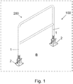
- FIG 1 is a schematic view of a safety railing 200 comprising an arrangement 100 for attaching a falling post of the invention and arranged to a vehicle V.
- the vehicle V is a mining vehicle or a construction vehicle. In mines and at other work sites different type of vehicles are used.
- the vehicles may be provided with one or more working devices for executing designed work tasks at the work site.
- the vehicle may be a wheel loader, a transport vehicle or dumper, a rock drilling rig, an excavator or a lifting machine, for example.
- vehicle V may be any other type of a utility vehicle, such as a tractor, a truck, a farming machine, a forestry machine etc.
- the arrangement 100 comprises a stand 2 that has an attachment element 3 for attaching the falling post 1 to a base structure B.
- the attachment element 3 shown in figures comprises bolt holes but, of course, the attachment element may be realized various ways.
- the base structure B is a part or component of the vehicle V.
- vertical or standing position means here a position where the post 1 lies when the safety railing 200 is arranged for securing safety of personnel
- horizontal or recumbent position means a position where the safety railing 200 has been lowered or overturned in order to lower the height thereof.
- the stand 2 comprises at least one groove 5 arranged laterally in respect of the post 1. In the embodiment shown in Figures, there are two grooves 5 arranged opposite sides of the stand 2.
- the post 1 comprises at least one projection 6 extending in a lateral direction from the post 1. In the embodiment shown in Figures, there are two projections 6 extending opposite directions from the post 1.
- the grooves 5 are arranged in respect of the projections 6 such that when the post 1 is in the standing position (shown in Figure 5 ), the projections 6 lie in the grooves 5, and thereby locks the post 1 in the standing position and in respect of the stand 2.
- the projections 6 are attached to the post 1 such that they may move in respect of the stand 2 in a longitudinal direction of the post 1.
- the projections 6 are attached to a sleeve 17 that glides on the post 1.
- the sleeve comprises two long apertures and the post 1 a bolt and nut arranged in said apertures.
- the apertures and the bolt and nut limits and guides the movement of the projections 6 on the post 1.
- an actuator 10 is arranged in the post 1.
- the actuator 10 is adapted to urge the projection(s) 6 towards the pin 4 and allow said projection(s) 6 being lifted by a guidance surface 7 to move away from the pin 4.
- the actuator is a coil spring.
- the actuator may also be e.g. mechanical spring of another type, a gas spring etc.
- the guidance surface 7 may have different shapes. In an embodiment, the shape is straight.
- the exterior of the stand 2 comprises guidance surfaces 7 that end to the grooves 5.
- the guidance surfaces 7 are adapted to lift (see Figures 3 and 4 ) the projections 6 during movement of the post 1 from its horizontal position to the vertical position and guide said projections 6 to move in the grooves 5.
- the pin 4 may be arranged acentrically with respect to the convex-shaped upper sections, such that the distance of upper part of the guidance surface 7 from the pin 4 is more than said distance in lower parts of said surface 7. Thanks to this feature, the projections 6 move away from the pin 4 during the raising of the post 1 and, simultaneously, the actuator 10 is "primed", e.g. in case of spring, the spring is tensioned. The tension is at least partly released when the projections move in the grooves 5.
- the arrangement 100 comprises further a lever 8 attached rotatable in the stand 2.
- the lever 8 has a first end 9, length of which is arranged to extend past the guidance surface 7 when the post 1 is in the horizontal position.
- the projections 6 that move on the guidance surface 7 together with raising post will 1 push the first end 9 of the lever and rotate the lever 8 in a first direction D1 therewith (shown in Figure 2 ) .
- the projections 6 push the first ends 9 moving on the respective guidance surfaces 7 ahead (as shown in Figure 4 ) until the projections 6 reach the grooves 5. Then the projections 6 move or drop into the grooves 5 and, simultaneously, push down the first ends 9 of the lever. As a result, the first ends 9 are situated under the projections 6 settled in the grooves 5. The post 1 and the safety railing 200 is then in the standing position and locked in this position by the projections 6 in the grooves 5 as shown in Figure 5 .
- the movement of the projections 6 in the first direction D1 may be stopped just above the grooves 5 by a high rear edge 12 of the groove 5.
- the two projections centre and guide themselves against respective rear edges.
- the high rear edge is not an essential feature of the structure.
- the lever 8 is activated to rotate in a second direction D2 opposite to the first direction.
- the activation may be done by pressing second end of lever 15 e.g. by foot.
- the first ends 9 of the lever are adapted to lift the projections 6 away from the respective grooves 5, as shown in Figure 6 .
- the post 1 is released and may be turn over to the horizontal position.
- the lever 8 shown in Figures comprises two first ends 9 and an arc-like connecting piece 14 connecting the first ends.
- the arc-like connecting piece 14 establishes the second end 15 of the lever.
- the embodiment shown in Figures comprises two grooves 5, two projections 6 and two guidance surfaces 7.
- the numbers of the grooves, projections and guidance surfaces are equal, but this is not compulsory.
- the lever 8 is in its extreme position in a second direction D2 of rotation, the first end 9 thereof is arranged to limit a length L (shown in Figure 2 ) of the groove 5 to a length shorter than width W (shown in Figure 7 ) of the projection 6.
- An example of this kind of position is shown in Figure 7 .
- the lever 8 is prohibiting the projection 6 entering in the groove 5.
- a safety railing 200 comprising at least two posts and arrangements 100 from a standing position to recumbent position.
- the projection(s) 6 will not go back spontaneously in said groove (s), but is/are supported by the first end(s) 9.
- the operator may leave said arrangement and concentrate to operate with a next arrangement 100. This way even a very long safety railing 200 can be turned over by just one operator.
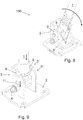
- Figure 9 is a schematic perspective view of another embodiment of the arrangement.
- the projection 6 is arranged fixedly in the post 1.
- the stand 2 comprises vertically elongated mounting holes 11 that receives the pin 4 attached to the post 1.
- the pin 4 and also the post 1 may move in the mounting holes 11 in vertical direction.
- the guidance surface 7 lifts the projection 6, the pin 4 and the post 1 therewith such that the projection 6 enters at a corresponding groove 5, and then the projection 6 and the post 1 therewith drops in the groove 5.
- Figure 10 is a schematic perspective view of a third embodiment of the arrangement.
- the projection 6 is arranged fixedly in the post 1.
- the post 1 comprises vertically elongated mounting hole 11 for receiving the pin 4 attached to the stand 2.
- the post 1 may move in relation to the pin 4 in direction of the elongation.
- the guidance surface 7 lifts the projection 6 and the post 1 therewith such that the projection 6 enters at a corresponding groove 5, and then the projection 6 and the post 1 therewith drops in the groove 5.
- the lever 8 is not shown in Figure 9 in order to simplify the presentation.
Landscapes
- Engineering & Computer Science (AREA)
- Mechanical Engineering (AREA)
- Vehicle Step Arrangements And Article Storage (AREA)
Claims (15)
- Anordnung zur Befestigung eines fallenden Pfostens (1) auf einer Basisstruktur (B), wobei der Pfosten (1) zwischen einer stehenden und einer liegenden Position drehbar beweglich ist,
wobei die Anordnung umfasst- einen Ständer (2), umfassend ein Befestigungselement (3) zum Befestigen des fallenden Pfostens an der Basisstruktur,- den Pfosten (1) schwenkbar an dem Ständer (2) durch einen Stift (4) befestigt, wobei der Pfosten eine Fähigkeit aufweist, aus der stehenden Position zu der liegenden Position in Bezug auf den Ständer zu drehen,- den Ständer (2), der mindestens eine Kerbe (5) umfasst, die seitlich in Bezug auf den Pfosten (1) angeordnet ist, und- den Pfosten (1), der mindestens einen Fortsatz (6) umfasst, der sich in einer seitlichen Richtung von dem Pfosten erstreckt,dadurch gekennzeichnet, dass- die mindestens eine Kerbe (5) in Bezug auf den mindestens einen Fortsatz (6) so angeordnet ist, dass, wenn der Ständer in der stehenden Position ist, der mindestens eine Fortsatz (6) in der mindestens einen Kerbe (5) liegt und dadurch den Pfosten (1) in der stehenden Position verriegelt,- der mindestens eine Fortsatz (6) an dem Pfosten (1) so befestigt ist, dass er die Fähigkeit aufweist, sich in Bezug auf den Ständer (2) in einer Längsrichtung des Pfostens (1) zu bewegen,- eine Außenseite des Ständers (2) eine Führungsfläche (7) aufweist, die an der mindestens einen Kerbe (5) endet und angeordnet ist, den mindestens einen Fortsatz (6) anzuheben und den Fortsatz (6) zu führen, sich in die mindestens eine Kerbe (5) zu bewegen,- die Anordnung (100) weiter einen Hebel (8) umfasst, der drehbar in dem Ständer (2) befestigt ist,- der Hebel (8) ein erstes Ende (9) beinhaltet, dessen Länge angeordnet ist, sich über die Führungsfläche (7) hinaus zu erstrecken, wenn sich der Pfosten in der liegenden Position befindet, sodass- der mindestens eine Fortsatz (6), der angeordnet ist, sich auf der Führungsfläche (7) zu bewegen, ausgebildet ist, das erste Ende (9) des Hebels anzuschieben und den Hebel (8) damit in erster Richtung zu drehen, und- der mindestens eine Fortsatz (6) angeordnet ist, das erste Ende (9) gleichzeitig mit Bewegung in die mindestens eine Kerbe (5) nach unten zu schieben, sodass, wenn der Pfosten (1) in der stehenden Position ist, das erste Ende (9) des Hebels unter dem mindestens einen Fortsatz (6) gelegen ist, der in der mindestens einen Kerbe (5) liegt, und wobei- der Hebel (8) aktiviert wird, um in einer zweiten Richtung, der ersten Richtung entgegengesetzt, zu drehen, wobei das erste Ende (9) des Hebels ausgebildet ist, den mindestens einen Fortsatz (6) von der mindestens einen Kerbe (5) abzuheben, sodass der Pfosten (1) zu der liegenden Position bewegt werden kann. - Anordnung nach Anspruch 1, wobei der mindestens eine Fortsatz (6) in dem Pfosten (1) in Längsrichtung des Pfostens (1) beweglich angeordnet ist.
- Anordnung nach Anspruch 2, wobei ein Stellglied (10) in dem Pfosten (1) angeordnet ist, wobei das Stellglied (10) ausgebildet ist, den Fortsatz (6) zu dem Stift (4) zu pressen und dem Fortsatz (6) zu erlauben, durch die Führungsfläche (7) angehoben zu werden, um sich von dem Stift (4) wegzubewegen.
- Anordnung nach Anspruch 1, wobei- der mindestens eine Fortsatz (6) in dem Pfosten fixiert angeordnet ist,- der Ständer (2) vertikal längliche Montagelöcher (11) zum Aufnehmen des Stifts (4), der am Pfosten (1) befestigt ist, umfasst, sodass- die Führungsfläche (7) angeordnet ist, den Stift (4) und damit den Pfosten (1) in Führung des länglichen Montagelochs (11) anzuheben.
- Anordnung nach Anspruch 1, wobei- der mindestens eine Fortsatz (6) in dem Pfosten (1) fixiert angeordnet ist,- der Pfosten (1) vertikal längliche Montagelöcher (11) zum Aufnehmen des Stifts (4), der am Ständer (2) befestigt ist, umfasst, sodass- die Führungsfläche (7) angeordnet ist, den Pfosten (1) damit in Führung des länglichen Montagelochs (11) anzuheben.
- Anordnung nach einem der vorstehenden Ansprüche, wobei der Ständer (2) zwei Kerben (5) umfasst, die an gegenüberliegenden Seiten des Ständers angeordnet sind, und bzw.,- der Pfosten (1) zwei Fortsätze (6) umfasst, die sich in entgegengesetzten Richtungen von dem Pfosten erstrecken.
- Anordnung nach einem der vorstehenden Ansprüche, wobei ein oberer Abschnitt der Führungsfläche (7) ein konvexes Profil aufweist.
- Anordnung nach einem der vorstehenden Ansprüche, wobei die mindestens eine Kerbe (5) eine hintere Kante (12) umfasst, die sich von dem Boden der Kerbe (5) höher erstreckt als eine vordere Kante (13), die mit der Führungsfläche (7) verbunden ist.
- Anordnung nach einem der vorstehenden Ansprüche, wobei- wenn der Hebel (8) in seiner extremen Position in einer zweiten Drehrichtung (D2) ist,- das erste Ende (9) des Hebels angeordnet ist, an der mindestens einen Kerbe (5) zu liegen,- sodass das erste Ende (9) Länge (L) der mindestens einen Kerbe (5) auf eine Länge begrenzt, die kürzer als Breite (W) des Fortsatzes (6) ist,- der Hebel (8) dadurch ein Eindringen des Fortsatzes (6) in die Kerbe (5) verhindert.
- Anordnung nach Anspruch 9, wobei- der Hebel (8) so dimensioniert ist, dass, wenn das erste Ende (9) die Länge (L) der mindestens einen Kerbe (5) auf eine Länge begrenzt, die kürzer als Breite (W) des Fortsatzes (6) ist,- das zweite Ende (15) des Hebels an derselben Seite mit dem ersten Ende (9) in Bezug auf eine imaginäre vertikale Ebene (P) liegt, die in und parallel mit einem Drehstift (16) des Hebels (8) angeordnet ist.
- Anordnung nach einem der vorstehenden Ansprüche, wobei der Hebel (8) zwei erste Enden (9) und ein bogenförmiges Verbindungsstück (14) dazwischen umfasst, wobei das bogenförmige Verbindungsstück das zweite Ende (15) des Hebels bildet.
- Anordnung nach einem der vorstehenden Ansprüche, wobei der Hebel (8) eine Verlängerung (16) umfasst, die sich zu einer gegenüberliegenden Seite des Ständers (2) als das zweite Ende (15) des Hebels erstreckt.
- Anordnung nach einem der vorstehenden Ansprüche, wobei der Stift (4) azentrisch in Bezug auf die Führungsfläche (7) angeordnet ist, sodass der Abstand von oberem Teil der Führungsfläche (7) von dem Stift 4 mehr ist als der Abstand in unteren Teilen der Führungsfläche (7).
- Fahrzeug (V), umfassend die Anordnung (100) nach einem der vorstehenden Ansprüche.
- Fahrzeug nach Anspruch 14, wobei das Fahrzeug (V) ein Bergbaufahrzeug ist und wobei die Anordnung (100) in einem Schutzgeländer (200) des Bergbaufahrzeugs angeordnet ist.
Priority Applications (4)
| Application Number | Priority Date | Filing Date | Title |
|---|---|---|---|
| PL18192048T PL3616997T3 (pl) | 2018-08-31 | 2018-08-31 | Układ |
| EP18192048.9A EP3616997B1 (de) | 2018-08-31 | 2018-08-31 | Anordnung |
| AU2019462265A AU2019462265B2 (en) | 2018-08-31 | 2019-08-19 | Arrangement |
| US19/198,869 US20250263932A1 (en) | 2018-08-31 | 2025-05-05 | Arrangement |
Applications Claiming Priority (1)
| Application Number | Priority Date | Filing Date | Title |
|---|---|---|---|
| EP18192048.9A EP3616997B1 (de) | 2018-08-31 | 2018-08-31 | Anordnung |
Publications (2)
| Publication Number | Publication Date |
|---|---|
| EP3616997A1 EP3616997A1 (de) | 2020-03-04 |
| EP3616997B1 true EP3616997B1 (de) | 2021-02-24 |
Family
ID=63452572
Family Applications (1)
| Application Number | Title | Priority Date | Filing Date |
|---|---|---|---|
| EP18192048.9A Active EP3616997B1 (de) | 2018-08-31 | 2018-08-31 | Anordnung |
Country Status (2)
| Country | Link |
|---|---|
| EP (1) | EP3616997B1 (de) |
| PL (1) | PL3616997T3 (de) |
Cited By (1)
| Publication number | Priority date | Publication date | Assignee | Title |
|---|---|---|---|---|
| US12495784B2 (en) | 2023-03-31 | 2025-12-16 | Cnh Industrial America Llc | System and method for controlling the operation of an agricultural sprayer |
Family Cites Families (3)
| Publication number | Priority date | Publication date | Assignee | Title |
|---|---|---|---|---|
| GB926289A (en) * | 1960-05-19 | 1963-05-15 | Torridon Steel Ltd | Tank vehicles and walkways for tank vehicles |
| US4759437A (en) * | 1986-04-25 | 1988-07-26 | Fmc Corporation | Handrail for aircraft belt loader |
| WO2016041017A1 (en) * | 2014-09-19 | 2016-03-24 | Caterpillar Underground Mining Pty Ltd | Handrail locking mechanism |
-
2018
- 2018-08-31 EP EP18192048.9A patent/EP3616997B1/de active Active
- 2018-08-31 PL PL18192048T patent/PL3616997T3/pl unknown
Non-Patent Citations (1)
| Title |
|---|
| None * |
Cited By (1)
| Publication number | Priority date | Publication date | Assignee | Title |
|---|---|---|---|---|
| US12495784B2 (en) | 2023-03-31 | 2025-12-16 | Cnh Industrial America Llc | System and method for controlling the operation of an agricultural sprayer |
Also Published As
| Publication number | Publication date |
|---|---|
| PL3616997T3 (pl) | 2021-07-12 |
| EP3616997A1 (de) | 2020-03-04 |
Similar Documents
| Publication | Publication Date | Title |
|---|---|---|
| DE602004012201T2 (de) | Hubmast für einen Gabelstapler | |
| CA2924982C (en) | Mobile well servicing units and related methods | |
| US7905324B2 (en) | Access system for a moveable vehicle | |
| EP2383405A2 (de) | Gleitbeladungsplattform für das Baugewerbe | |
| JP5160555B2 (ja) | 航空機用ローダのための仕切装置 | |
| US6186279B1 (en) | Low-rise vehicle lift for use over a pit | |
| US12312814B2 (en) | Arrangement | |
| WO2004094212A1 (de) | Gabelhubwagen | |
| EP3616997A1 (de) | Anordnung | |
| EP2088115B1 (de) | Kran | |
| US20250263932A1 (en) | Arrangement | |
| GB2420367A (en) | Post driver | |
| DE1580265B2 (de) | Lastkraftwagen mit einer Plattform zur Mitnahme eines Hubladers | |
| US4506866A (en) | Vehicle hoist | |
| JPS59158794A (ja) | 鉄塔組立用クレ−ン | |
| US4071115A (en) | Multi-story lift device | |
| DE102008046867B4 (de) | Elektrokettenzug mit Lastausleger | |
| JP2007117246A (ja) | 転落防止具及びその使用方法、並びに転落防止柵及びその使用方法 | |
| CN107825999A (zh) | 一种多段调节的锁扣系统 | |
| CH670622A5 (de) | ||
| KR200435429Y1 (ko) | 고소작업용 차량의 난간체 | |
| JP6610088B2 (ja) | 移動式クレーンに備えられたステップ機構 | |
| EP1243465A2 (de) | Absturzsicherung für begehbare Pritschen | |
| JP5123653B2 (ja) | エレベータ式駐車装置およびそのパレットロック装置 | |
| DE102004059699A1 (de) | Flurförderzeug mit einem höhenveränderlichen Lastaufnahmemittel |
Legal Events
| Date | Code | Title | Description |
|---|---|---|---|
| PUAI | Public reference made under article 153(3) epc to a published international application that has entered the european phase |
Free format text: ORIGINAL CODE: 0009012 |
|
| STAA | Information on the status of an ep patent application or granted ep patent |
Free format text: STATUS: THE APPLICATION HAS BEEN PUBLISHED |
|
| AK | Designated contracting states |
Kind code of ref document: A1 Designated state(s): AL AT BE BG CH CY CZ DE DK EE ES FI FR GB GR HR HU IE IS IT LI LT LU LV MC MK MT NL NO PL PT RO RS SE SI SK SM TR |
|
| AX | Request for extension of the european patent |
Extension state: BA ME |
|
| STAA | Information on the status of an ep patent application or granted ep patent |
Free format text: STATUS: REQUEST FOR EXAMINATION WAS MADE |
|
| 17P | Request for examination filed |
Effective date: 20200904 |
|
| RBV | Designated contracting states (corrected) |
Designated state(s): AL AT BE BG CH CY CZ DE DK EE ES FI FR GB GR HR HU IE IS IT LI LT LU LV MC MK MT NL NO PL PT RO RS SE SI SK SM TR |
|
| GRAP | Despatch of communication of intention to grant a patent |
Free format text: ORIGINAL CODE: EPIDOSNIGR1 |
|
| STAA | Information on the status of an ep patent application or granted ep patent |
Free format text: STATUS: GRANT OF PATENT IS INTENDED |
|
| INTG | Intention to grant announced |
Effective date: 20201026 |
|
| GRAS | Grant fee paid |
Free format text: ORIGINAL CODE: EPIDOSNIGR3 |
|
| GRAA | (expected) grant |
Free format text: ORIGINAL CODE: 0009210 |
|
| STAA | Information on the status of an ep patent application or granted ep patent |
Free format text: STATUS: THE PATENT HAS BEEN GRANTED |
|
| AK | Designated contracting states |
Kind code of ref document: B1 Designated state(s): AL AT BE BG CH CY CZ DE DK EE ES FI FR GB GR HR HU IE IS IT LI LT LU LV MC MK MT NL NO PL PT RO RS SE SI SK SM TR |
|
| REG | Reference to a national code |
Ref country code: CH Ref legal event code: EP |
|
| REG | Reference to a national code |
Ref country code: AT Ref legal event code: REF Ref document number: 1364036 Country of ref document: AT Kind code of ref document: T Effective date: 20210315 |
|
| REG | Reference to a national code |
Ref country code: IE Ref legal event code: FG4D |
|
| REG | Reference to a national code |
Ref country code: DE Ref legal event code: R096 Ref document number: 602018012945 Country of ref document: DE |
|
| REG | Reference to a national code |
Ref country code: FI Ref legal event code: FGE |
|
| REG | Reference to a national code |
Ref country code: SE Ref legal event code: TRGR |
|
| REG | Reference to a national code |
Ref country code: LT Ref legal event code: MG9D |
|
| REG | Reference to a national code |
Ref country code: NL Ref legal event code: MP Effective date: 20210224 |
|
| PG25 | Lapsed in a contracting state [announced via postgrant information from national office to epo] |
Ref country code: GR Free format text: LAPSE BECAUSE OF FAILURE TO SUBMIT A TRANSLATION OF THE DESCRIPTION OR TO PAY THE FEE WITHIN THE PRESCRIBED TIME-LIMIT Effective date: 20210525 Ref country code: HR Free format text: LAPSE BECAUSE OF FAILURE TO SUBMIT A TRANSLATION OF THE DESCRIPTION OR TO PAY THE FEE WITHIN THE PRESCRIBED TIME-LIMIT Effective date: 20210224 Ref country code: BG Free format text: LAPSE BECAUSE OF FAILURE TO SUBMIT A TRANSLATION OF THE DESCRIPTION OR TO PAY THE FEE WITHIN THE PRESCRIBED TIME-LIMIT Effective date: 20210524 Ref country code: LT Free format text: LAPSE BECAUSE OF FAILURE TO SUBMIT A TRANSLATION OF THE DESCRIPTION OR TO PAY THE FEE WITHIN THE PRESCRIBED TIME-LIMIT Effective date: 20210224 Ref country code: PT Free format text: LAPSE BECAUSE OF FAILURE TO SUBMIT A TRANSLATION OF THE DESCRIPTION OR TO PAY THE FEE WITHIN THE PRESCRIBED TIME-LIMIT Effective date: 20210624 Ref country code: NO Free format text: LAPSE BECAUSE OF FAILURE TO SUBMIT A TRANSLATION OF THE DESCRIPTION OR TO PAY THE FEE WITHIN THE PRESCRIBED TIME-LIMIT Effective date: 20210524 |
|
| REG | Reference to a national code |
Ref country code: AT Ref legal event code: MK05 Ref document number: 1364036 Country of ref document: AT Kind code of ref document: T Effective date: 20210224 |
|
| PG25 | Lapsed in a contracting state [announced via postgrant information from national office to epo] |
Ref country code: RS Free format text: LAPSE BECAUSE OF FAILURE TO SUBMIT A TRANSLATION OF THE DESCRIPTION OR TO PAY THE FEE WITHIN THE PRESCRIBED TIME-LIMIT Effective date: 20210224 Ref country code: NL Free format text: LAPSE BECAUSE OF FAILURE TO SUBMIT A TRANSLATION OF THE DESCRIPTION OR TO PAY THE FEE WITHIN THE PRESCRIBED TIME-LIMIT Effective date: 20210224 Ref country code: LV Free format text: LAPSE BECAUSE OF FAILURE TO SUBMIT A TRANSLATION OF THE DESCRIPTION OR TO PAY THE FEE WITHIN THE PRESCRIBED TIME-LIMIT Effective date: 20210224 |
|
| PG25 | Lapsed in a contracting state [announced via postgrant information from national office to epo] |
Ref country code: IS Free format text: LAPSE BECAUSE OF FAILURE TO SUBMIT A TRANSLATION OF THE DESCRIPTION OR TO PAY THE FEE WITHIN THE PRESCRIBED TIME-LIMIT Effective date: 20210624 |
|
| PG25 | Lapsed in a contracting state [announced via postgrant information from national office to epo] |
Ref country code: SM Free format text: LAPSE BECAUSE OF FAILURE TO SUBMIT A TRANSLATION OF THE DESCRIPTION OR TO PAY THE FEE WITHIN THE PRESCRIBED TIME-LIMIT Effective date: 20210224 Ref country code: EE Free format text: LAPSE BECAUSE OF FAILURE TO SUBMIT A TRANSLATION OF THE DESCRIPTION OR TO PAY THE FEE WITHIN THE PRESCRIBED TIME-LIMIT Effective date: 20210224 Ref country code: AT Free format text: LAPSE BECAUSE OF FAILURE TO SUBMIT A TRANSLATION OF THE DESCRIPTION OR TO PAY THE FEE WITHIN THE PRESCRIBED TIME-LIMIT Effective date: 20210224 |
|
| REG | Reference to a national code |
Ref country code: DE Ref legal event code: R097 Ref document number: 602018012945 Country of ref document: DE |
|
| PG25 | Lapsed in a contracting state [announced via postgrant information from national office to epo] |
Ref country code: DK Free format text: LAPSE BECAUSE OF FAILURE TO SUBMIT A TRANSLATION OF THE DESCRIPTION OR TO PAY THE FEE WITHIN THE PRESCRIBED TIME-LIMIT Effective date: 20210224 Ref country code: RO Free format text: LAPSE BECAUSE OF FAILURE TO SUBMIT A TRANSLATION OF THE DESCRIPTION OR TO PAY THE FEE WITHIN THE PRESCRIBED TIME-LIMIT Effective date: 20210224 Ref country code: SK Free format text: LAPSE BECAUSE OF FAILURE TO SUBMIT A TRANSLATION OF THE DESCRIPTION OR TO PAY THE FEE WITHIN THE PRESCRIBED TIME-LIMIT Effective date: 20210224 |
|
| PLBE | No opposition filed within time limit |
Free format text: ORIGINAL CODE: 0009261 |
|
| STAA | Information on the status of an ep patent application or granted ep patent |
Free format text: STATUS: NO OPPOSITION FILED WITHIN TIME LIMIT |
|
| PG25 | Lapsed in a contracting state [announced via postgrant information from national office to epo] |
Ref country code: ES Free format text: LAPSE BECAUSE OF FAILURE TO SUBMIT A TRANSLATION OF THE DESCRIPTION OR TO PAY THE FEE WITHIN THE PRESCRIBED TIME-LIMIT Effective date: 20210224 Ref country code: AL Free format text: LAPSE BECAUSE OF FAILURE TO SUBMIT A TRANSLATION OF THE DESCRIPTION OR TO PAY THE FEE WITHIN THE PRESCRIBED TIME-LIMIT Effective date: 20210224 |
|
| 26N | No opposition filed |
Effective date: 20211125 |
|
| PG25 | Lapsed in a contracting state [announced via postgrant information from national office to epo] |
Ref country code: SI Free format text: LAPSE BECAUSE OF FAILURE TO SUBMIT A TRANSLATION OF THE DESCRIPTION OR TO PAY THE FEE WITHIN THE PRESCRIBED TIME-LIMIT Effective date: 20210224 |
|
| REG | Reference to a national code |
Ref country code: CH Ref legal event code: PL |
|
| PG25 | Lapsed in a contracting state [announced via postgrant information from national office to epo] |
Ref country code: MC Free format text: LAPSE BECAUSE OF FAILURE TO SUBMIT A TRANSLATION OF THE DESCRIPTION OR TO PAY THE FEE WITHIN THE PRESCRIBED TIME-LIMIT Effective date: 20210224 |
|
| REG | Reference to a national code |
Ref country code: BE Ref legal event code: MM Effective date: 20210831 |
|
| PG25 | Lapsed in a contracting state [announced via postgrant information from national office to epo] |
Ref country code: LI Free format text: LAPSE BECAUSE OF NON-PAYMENT OF DUE FEES Effective date: 20210831 Ref country code: IT Free format text: LAPSE BECAUSE OF FAILURE TO SUBMIT A TRANSLATION OF THE DESCRIPTION OR TO PAY THE FEE WITHIN THE PRESCRIBED TIME-LIMIT Effective date: 20210224 Ref country code: CH Free format text: LAPSE BECAUSE OF NON-PAYMENT OF DUE FEES Effective date: 20210831 |
|
| PG25 | Lapsed in a contracting state [announced via postgrant information from national office to epo] |
Ref country code: IS Free format text: LAPSE BECAUSE OF FAILURE TO SUBMIT A TRANSLATION OF THE DESCRIPTION OR TO PAY THE FEE WITHIN THE PRESCRIBED TIME-LIMIT Effective date: 20210624 Ref country code: LU Free format text: LAPSE BECAUSE OF NON-PAYMENT OF DUE FEES Effective date: 20210831 |
|
| PG25 | Lapsed in a contracting state [announced via postgrant information from national office to epo] |
Ref country code: IE Free format text: LAPSE BECAUSE OF NON-PAYMENT OF DUE FEES Effective date: 20210831 Ref country code: BE Free format text: LAPSE BECAUSE OF NON-PAYMENT OF DUE FEES Effective date: 20210831 |
|
| GBPC | Gb: european patent ceased through non-payment of renewal fee |
Effective date: 20220831 |
|
| PG25 | Lapsed in a contracting state [announced via postgrant information from national office to epo] |
Ref country code: CY Free format text: LAPSE BECAUSE OF FAILURE TO SUBMIT A TRANSLATION OF THE DESCRIPTION OR TO PAY THE FEE WITHIN THE PRESCRIBED TIME-LIMIT Effective date: 20210224 |
|
| P01 | Opt-out of the competence of the unified patent court (upc) registered |
Effective date: 20230603 |
|
| PG25 | Lapsed in a contracting state [announced via postgrant information from national office to epo] |
Ref country code: HU Free format text: LAPSE BECAUSE OF FAILURE TO SUBMIT A TRANSLATION OF THE DESCRIPTION OR TO PAY THE FEE WITHIN THE PRESCRIBED TIME-LIMIT; INVALID AB INITIO Effective date: 20180831 |
|
| PG25 | Lapsed in a contracting state [announced via postgrant information from national office to epo] |
Ref country code: GB Free format text: LAPSE BECAUSE OF NON-PAYMENT OF DUE FEES Effective date: 20220831 |
|
| PG25 | Lapsed in a contracting state [announced via postgrant information from national office to epo] |
Ref country code: MK Free format text: LAPSE BECAUSE OF FAILURE TO SUBMIT A TRANSLATION OF THE DESCRIPTION OR TO PAY THE FEE WITHIN THE PRESCRIBED TIME-LIMIT Effective date: 20210224 |
|
| PG25 | Lapsed in a contracting state [announced via postgrant information from national office to epo] |
Ref country code: MT Free format text: LAPSE BECAUSE OF FAILURE TO SUBMIT A TRANSLATION OF THE DESCRIPTION OR TO PAY THE FEE WITHIN THE PRESCRIBED TIME-LIMIT Effective date: 20210224 |
|
| PGFP | Annual fee paid to national office [announced via postgrant information from national office to epo] |
Ref country code: FI Payment date: 20250814 Year of fee payment: 8 |
|
| PGFP | Annual fee paid to national office [announced via postgrant information from national office to epo] |
Ref country code: DE Payment date: 20250702 Year of fee payment: 8 |
|
| PGFP | Annual fee paid to national office [announced via postgrant information from national office to epo] |
Ref country code: PL Payment date: 20250714 Year of fee payment: 8 |
|
| PGFP | Annual fee paid to national office [announced via postgrant information from national office to epo] |
Ref country code: FR Payment date: 20250721 Year of fee payment: 8 |
|
| PGFP | Annual fee paid to national office [announced via postgrant information from national office to epo] |
Ref country code: SE Payment date: 20250702 Year of fee payment: 8 |
|
| PGFP | Annual fee paid to national office [announced via postgrant information from national office to epo] |
Ref country code: CZ Payment date: 20250723 Year of fee payment: 8 |
|
| PG25 | Lapsed in a contracting state [announced via postgrant information from national office to epo] |
Ref country code: TR Free format text: LAPSE BECAUSE OF FAILURE TO SUBMIT A TRANSLATION OF THE DESCRIPTION OR TO PAY THE FEE WITHIN THE PRESCRIBED TIME-LIMIT Effective date: 20210224 |