EP3623262B1 - Semi-remorque - Google Patents
Semi-remorque Download PDFInfo
- Publication number
- EP3623262B1 EP3623262B1 EP19197621.6A EP19197621A EP3623262B1 EP 3623262 B1 EP3623262 B1 EP 3623262B1 EP 19197621 A EP19197621 A EP 19197621A EP 3623262 B1 EP3623262 B1 EP 3623262B1
- Authority
- EP
- European Patent Office
- Prior art keywords
- trailer
- extension frame
- semi
- chassis
- bolster
- Prior art date
- Legal status (The legal status is an assumption and is not a legal conclusion. Google has not performed a legal analysis and makes no representation as to the accuracy of the status listed.)
- Active
Links
Images


Classifications
-
- B—PERFORMING OPERATIONS; TRANSPORTING
- B62—LAND VEHICLES FOR TRAVELLING OTHERWISE THAN ON RAILS
- B62D—MOTOR VEHICLES; TRAILERS
- B62D63/00—Motor vehicles or trailers not otherwise provided for
- B62D63/06—Trailers
- B62D63/061—Foldable, extensible or yielding trailers
-
- B—PERFORMING OPERATIONS; TRANSPORTING
- B62—LAND VEHICLES FOR TRAVELLING OTHERWISE THAN ON RAILS
- B62D—MOTOR VEHICLES; TRAILERS
- B62D53/00—Tractor-trailer combinations; Road trains
- B62D53/04—Tractor-trailer combinations; Road trains comprising a vehicle carrying an essential part of the other vehicle's load by having supporting means for the front or rear part of the other vehicle
- B62D53/06—Semi-trailers
- B62D53/067—Multi-purpose, convertible or extendable load surface semi-trailers
-
- B—PERFORMING OPERATIONS; TRANSPORTING
- B62—LAND VEHICLES FOR TRAVELLING OTHERWISE THAN ON RAILS
- B62D—MOTOR VEHICLES; TRAILERS
- B62D21/00—Understructures, i.e. chassis frame on which a vehicle body may be mounted
- B62D21/18—Understructures, i.e. chassis frame on which a vehicle body may be mounted characterised by the vehicle type and not provided for in groups B62D21/02 - B62D21/17
- B62D21/20—Understructures, i.e. chassis frame on which a vehicle body may be mounted characterised by the vehicle type and not provided for in groups B62D21/02 - B62D21/17 trailer type, i.e. a frame specifically constructed for use in a non-powered vehicle
Definitions
- This invention relates to semi-trailers, and in particular to semi-trailers used for the road transport of container boxes.
- the invention particularly relates to telescopically length adjustable sliding bogie trailers or sliding skeletal trailers used for the transport of container boxes. Examples of this type of trailer are described in GB 2 335 891 , DE-U1-9306626 and EP 3 141 422 .
- a dump trailer is disclosed in DE1192933 having an outer frame with an associated bottomless inner frame slidably mounted on the outer frame so that when it is pushed back by rams, it discharges the load carried on the trailer within the outer frame through the open bottom of the inner frame.
- a telescopically adjustable trailer is disclosed in CN 201120903 .
- a semi-trailer including:
- the upper roller assembly is mounted inboard of the lower roller assembly.
- both roller assemblies are mounted on the rear trailer part.
- the upper roller assembly engages an upper face of the extension frame and the lower roller assembly engages a lower face of the extension frame.
- locking means is provided for releasably locking the extension frame in the stored position, or in the extended position.
- the locking means comprises complementary interengagable male and female formations on the rear trailer part and on the extension frame.
- the male formations comprise a pair of spaced-apart locking bosses on the rear trailer part and the female formations comprise two longitudinally spaced-apart pairs of receivers on the extension frame.
- the locking means comprises a pair of ram operated locking bolts mounted in parallel on the rear trailer part for movement between a retracted released position and an extended engaged position for engagement with complementary upright receivers on the extension frame.
- the locking bolts are mounted in a horizontal orientation at a rear end of the chassis.
- the bolster assembly on the extension frame comprises a pair of spaced-apart adjustable bolsters mounted on the extension frame, each adjustable bolster being movable between a raised in-use position on the extension frame and a lowered stored position on the extension frame.
- each adjustable bolster is pivotally mounted on the extension frame for movement between the raised positon and the lowered position on the extension frame.
- the adjustable bolsters are mounted on a cross-beam at an outer end of the extension frame and the cross-beam is nestably engagable within a complementary receiver slot on the trailer chassis when the extension frame is in the retracted stored position on the trailer chassis.
- the bolster assembly on the trailer chassis for cooperation with the bolster assembly on the extension frame comprises a pair of folding bolsters pivotally mounted on the trailer chassis for movement between a lowered stored position on the trailer chassis and a raised operative position on the trailer chassis.
- the trailer chassis has a pair of spaced-apart parallel longitudinal beams and each folding bolster is located at or below a top surface of the longitudinal beams and between the longitudinal beams in the stored position and the folding bolster extends laterally outwardly of a longitudinal beam when in the operative position.
- the extension frame is slidably movable on the chassis between the retracted stored position on the chassis, a partially extended positon on the chassis and a fully extended position on the chassis.
- the rearmost twistlock on the extension frame is located such that a rear end of a forty foot container box is positioned 12 metres from a kingpin on the chassis when the extension frame is in the partially extended position and a rear end of a forty-five foot container box is positioned 12.15 metres from the kingpin when the extension frame in the fully extended position.
- a front end of the trailer chassis is telescopically extendable to position a twistlock assembly thereon for cooperation with the rearmost twist lock assembly on the extension frame when the extension frame is in the fully extended position for mounting a forty-five foot container on the semi-trailer.
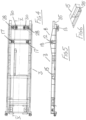
- the semi-trailer 1 is largely similar to the sliding bogie trailer described in our previous patent specification EP 3141422 , and essentially comprises a trailer chassis comprising a front trailer part 2 and a complementary rear trailer part 3 which are slidably interconnected for telescopic movement between a collapsed position as shown in Fig. 1 and an extended position as shown in Fig. 2 .
- the front trailer part 2 has a kingpin 4 for attachment to a tractor vehicle for towing the semi-trailer 1.
- a number of bolster assemblies 5a-5f are longitudinally spaced-apart on the semi-trailer 1 for mounting container boxes of various size on the semi-trailer 1 between associated pairs of bolster assemblies 5a-5f.
- the rear trailer part 3 is mounted on wheels 7 and has an elevator 8 for sliding the rearmost wheels 7 under the bolster assembly 5e at a rear end of the front trailer part 2 when moving the semi-trailer 1 between the collapsed position shown in Fig. 1 and the extended position shown in Fig. 2 .
- This arrangement is described more fully in EP 3141422 and for the sake of brevity need not be repeated here.
- an extension frame 10 is slidably mounted on the rear trailer part 3 at a rear end of the rear trailer part 3 for movement between a retracted stored position on the rear trailer part 3 as shown in Fig. 1 and an extended position on the rear trailer part 3 as shown in Fig. 2 for increasing the length of the semi-trailer 1 in order to carry either two twenty foot containers or a forty foot container on the semi-trailer 1.
- the extension frame 10 slidably engages the rear trailer part 3 by means of a pair of longitudinally spaced-apart roller assemblies 12, 13 engaged between the rear trailer part 3 and the extension frame 10.
- the roller assemblies 12, 13 comprise an upper roller assembly 12 engaged between a top of the extension frame 10 and the rear trailer part 3 and a lower roller assembly 13 engaged between a bottom of the extension frame 10 and the rear trailer part 3.
- the upper roller assembly 12 is mounted inboard of the lower roller assembly 13, in this case that is forwardly of the lower roller assembly 13 on the rear trailer part 3.
- the rear trailer part 3 comprises a pair of spaced-apart substantially parallel longitudinal I-beams 14, 15 interconnected by cross members 16 extending therebetween.
- the upper roller assembly 12 comprises a pair of rollers 17 rotatably mounted on a cross member 16 extending between ramps 18 of the elevator 8.
- the lower roller assembly 13 comprises a pair of rollers 28 mounted on the rearmost cross member 16 on the rear trailer part 3.
- the extension frame 10 comprises a pair of spaced-apart substantially parallel longitudinal I-beams 20, 21 interconnected by cross members 22 and a rear cross-beam 23. It will be noted that the spacing of the longitudinal beams 20, 21 of the extension frame 10 is narrower than the spacing of the longitudinal beams 14, 15 of the rear trailer part 3 so that they will fit between the longitudinal beams 14, 15 of the rear trailer part 3.
- Each longitudinal beam 20, 21 of the extension frame 10 has an upper face 25 and a lower face 26.
- the extension frame 10 slides on the rear trailer part 3 with the flat upper faces 25 of the longitudinal beams 20, 21 engaging the rollers 17 of the upper roller assembly 12 and the lower flat faces 26 of the I-beams 20, 21 engaging the rollers 28 of the lower roller assembly 13. It will be noted that the bottom face 26 of each longitudinal beam 20, 21 of the extension frame 10 is tapered upwardly at a leading or front end 29.
- Locking means is provided for releasably locking the extension frame 10 on the rear trailer part 3 in either the stored position, or the extended position.
- the locking means comprises a pair of upstanding locking bosses 30 on the rearmost cross member 16 of the rear trailer part 3 which are releasably engagable with complementary pairs of female receiver slots 31 on cross members 22 of the extension frame 10. Pneumatic rams raise and lower the locking bosses 30 for engagement/disengagement with the receiver slots 31.
- the bosses 30 could be manually operated.
- the rear cross-beam 23 on the extension frame 10 projects laterally outwardly of the longitudinal beams 20, 21.
- the rearmost bolster assembly 5f comprises a pair of swinging bolsters 32, 33 which are pivotally movable on the rear cross-beam 23 between a raised in-use position as shown in Fig. 3 and a lowered stored position as shown in Fig. 1 in which each bolster 32, 33 is folded forwardly of the cross-beam 23.
- rear cross-beam 23 is nestably engagable within a complementary receiver slot 35 at a rear end of the each longitudinal beam 14, 15 of the rear trailer part 3.
- the front trailer part 2 comprises a pair of spaced-apart substantially parallel longitudinal I-beams 40, 41. Intermediate the ends of the longitudinal beams 40, 41 a well 42 is formed for reception of a bolster frame 43, spanning between the longitudinal beams 40, 41 and perpendicular thereto, and carrying the bolster assemblies 5c and 5d.
- the rearmost bolster assembly 5d cooperates with the bolster assembly 5f on the extension frame 10 to mount a twenty foot container box on the semi-trailer 1.
- the bolster assembly 5d comprises a pair of folding bolsters 45, 46 pivotally mounted on the bolster frame 43 for movement between a lowered stored position on the front trailer part 2 as shown in Fig. 1 and a raised operative position on the front trailer part 2 as shown in Fig. 2 , Fig. 14 and Fig. 15 .
- each bolster 45, 46 In the folded position each bolster 45, 46 is located below a top surface 48 of the longitudinal beams 40, 41 and between the longitudinal beams 40, 41.
- the bolsters 45, 46 extend laterally outwardly of the longitudinal beams 40, 41 as best seen in Fig. 14 .
- the bolster assembly 5c has swinging bolsters 49, 50 pivotally mounted on the bolster frame 43 for movement between a folded position between the longitudinal beams 40, 41 and below the top surface 48 thereof and an in-use operative position extending laterally outwardly of the longitudinal beams 40, 41 as shown in Fig.14 in an elevated position above the top surface 48 of the longitudinal beams 40, 41 for cooperation with the front bolster assembly 5a to carry a twenty foot container box on the front trailer part 2.
- Each bolster assembly 5a-5f has conventional twistlocks 52 for releasable engagement with container boxes to secure the container boxes on the semi-trailer 1 in the usual way.
- the semi-trailer can be telescopically adjusted to carry different container boxes.
- a twenty foot container box can be carried between the bolster assemblies 5b and 5e.
- two twenty foot container boxes can be mounted in tandem between the bolster assemblies 5a and 5c and 5d and 5f, or a forty foot container box could be mounted between the bolster assemblies 5a and 5f, or a single twenty foot container box could be mounted between the bolster assemblies 5b and 5e.
- a thirty foot container box could be mounted between the bolster assemblies 5b and 5f. It will be appreciated that a wide range of container boxes of different sizes can be carried on the semi-trailer 1.
- extension frame 10 incorporated into a specific type of sliding bogie trailer
- extension frame 10 assembly could be incorporated in other trailers in a similar way.
- FIG. 16 to 19 there is shown another semi-trailer according to a second embodiment of the invention indicated generally by the reference numeral 60. Parts similar to those described previously are assigned the same reference numerals.
- the extension frame 10 is slidably movable on the rear trailer part 3 of the chassis between the retracted stored position on the chassis, a partially extended position on the chassis as shown in Fig. 16 and a fully extended position on the chassis as shown in Fig. 17 .
- the rearmost twistlock 52 on the extension frame 10 is located at position A for supporting a rear end of a forty foot container box twelve metres from the kingpin 4 at a front end of the chassis to facilitate carriage of a forty foot container box, or two twenty foot container boxes on the chassis as previously described.
- the rearmost twistlock 52 is located at a position B such that a rear end 61 of a forty-five foot container box 64 is positioned at 12.15 metres from the kingpin 4 to facilitate carriage of a forty-five foot container box 64 on the chassis.
- a front end 62 of the trailer chassis is telescopically extendable to position a twistlock assembly of the front bolster 5a for cooperation with the rearmost twistl ⁇ ck assembly 52 on the extension frame 10 when the extension frame 10 is in the fully extended position for mounting the forty-five foot container on the semi-trailer 60.
- the distance X between position A and position B is fifteen centimetres.
- the front end 62 extends forward by distance Y, being 612 millimetres.
- an alternative locking arrangement 70 is provided for locking the extension frame 10 on the rear trailer part 3 of the chassis.
- the locking arrangement 70 comprises a pair of ram operated locking bolts 71, 72 mounted transversely and horizontally in parallel at a rear end of the rear trailer part 3 for movement between a retracted release position and an extended engaged position for engagement with complementary upright receivers 31 on vertical webs 73, 74 of the I-beams 20, 21.
- the rearmost receivers 31 are associated with the fully collapsed stored position of the extension frame 10 on the rear trailer part 3.
- Forward pairs of receivers 31 on each web 73, 74 are associated with positions A and B for locking the extension frame 10 in the partially extended position and the fully extended position on the rear trailer part 3 of the chassis.
- the locking bolts 71, 72 and their associated operating rams 75 are mounted side-by-side transversely one in front of the other on the rear trailer part 3 facing in opposite directions for engagement with receivers 31 on the I-beams 20, 21.
Landscapes
- Engineering & Computer Science (AREA)
- Chemical & Material Sciences (AREA)
- Combustion & Propulsion (AREA)
- Transportation (AREA)
- Mechanical Engineering (AREA)
- Body Structure For Vehicles (AREA)
- Vehicle Cleaning, Maintenance, Repair, Refitting, And Outriggers (AREA)
Claims (14)
- Semi-remorque (1), incluant :un châssis de remorque (2, 3) monté sur des roues (7) et comportant un pivot d'attelage (4) destiné à être fixé sur un véhicule tracteur pour remorquer le châssis de remorque ;le châssis de remorque (2, 3) comprenant un châssis de remorque télescopique extensible (2, 3) comprenant deux parties de remorque (2, 3) interconnectées de manière coulissante, à savoir une partie de remorque avant (2) et une partie de remorque arrière (3) ;au moins deux ensembles de traverses (5) espacés longitudinalement sur le châssis de remorque (2, 3) permettant de monter une boîte à conteneurs sur le châssis de remorque (2, 3) pour le transport ;caractérisée en ce qu'un cadre d'extension (10) est monté de manière coulissante sur la partie de remorque arrière (3), à une extrémité arrière de la partie de remorque arrière (3), pour se déplacer entre une position rétractée rangée sur la partie de remorque arrière (3) et une position étendue sur la partie de remorque arrière (3), augmentant ainsi la longueur de la semi-remorque ;un ensemble traverse (5f) monté sur le cadre d'extension (10) pour coopérer avec l'un des ensembles traverses (5) sur le châssis de remorque (2, 3) pour monter une boîte à conteneurs sur le châssis de remorque (2, 3);le cadre d'extension (10) venant en prise de manière coulissante avec le châssis de remorque (3) au moyen d'une paire d'ensembles de rouleaux espacés longitudinalement (12, 13) en prise entre la partie de remorque arrière (3) et le cadre d'extension (10) ;les ensembles rouleaux (12, 13) comprenant un ensemble rouleau supérieur (12) en prise entre un sommet du cadre d'extension (10) et la partie de remorque arrière (3) et un ensemble rouleau inférieur (13) en prise entre un fond du cadre d'extension (10) et la partie de remorque arrière (3).
- Semi-remorque (1) selon la revendication 1, dans laquelle l'ensemble rouleau de supérieur (12) est monté à l'intérieur de l'ensemble de_rouleau inférieur (13)
- Semi-remorque (1) selon la revendication 1 ou la revendication 2, dans laquelle les deux ensembles rouleaux (12, 13) sont montés sur la partie de remorque arrière (3).
- Semi-remorque (1) selon l'une quelconque des revendications précédentes, dans laquelle l'ensemble rouleau supérieur (12) vient en prise avec une face supérieure (25) du cadre d'extension (10) et l'ensemble rouleau inférieur (13) vient en prise avec une face inférieure (26) du cadre d'extension (10).
- Semi-remorque (1) selon l'une quelconque des revendications précédentes, dans laquelle des moyens de verrouillage (30, 31) sont prévus pour verrouiller de manière amovible le cadre d'extension (10) dans la position rangée, ou dans la position étendue.
- Semi-remorque (1) selon la revendication 5, dans laquelle les moyens de verrouillage comprennent des formations mâles (30) et femelles (31) complémentaires emboîtables sur la partie de remorque arrière (3) et sur le cadre d'extension (10).
- Semi-remorque (1) selon la revendication 6, dans laquelle les formations mâles comprennent une paire de bossages de verrouillage (30) espacés sur la partie de remorque arrière (3), les formations femelles comprennent deux paires de récepteurs (31) espacées longitudinalement sur le cadre d'extension (10).
- Semi-remorque (1) selon la revendication 6, dans laquelle les_moyens de verrouillage comprennent une paire de boulons de verrouillage actionnés par vérin (71, 72) montés en parallèle sur la partie de remorque arrière (3) pour un mouvement entre une position rétractée relâchée et une position déployée en prise étendue pour une mise en prise avec des récepteurs verticaux complémentaires (31) sur le cadre d'extension (10).
- Semi-remorque (1) selon l'une quelconque des revendications précédentes, dans laquelle l'ensemble traverse (5f) sur le cadre d'extension (10) comprend une paire de traverses réglables à distance (32, 33) montés sur le cadre d'extension (10), chaque traverse réglable (32, 33) étant mobile entre une position d'utilisation relevée sur le cadre d'extension (10) et une position rangée abaissée sur le cadre d'extension (10).
- Semi-remorque (1) selon la revendication 9, dans laquelle les traverses réglables (32, 33) sont montées sur une entretoise (23) au niveau d'une extrémité externe du cadre d'extension (10) et l'entretoise (23) peut être mise en prise de manière amovible à l'intérieur d'une fente réceptrice (35) complémentaire sur le châssis de remorque (3) lorsque le cadre d'extension (10) est dans la position rangée rétractée sur le châssis de remorque (3).
- Semi-remorque (1) selon l'une quelconque des revendications précédentes, dans laquelle l'ensemble de traverses (5d) sur le châssis de remorque (2) destiné à coopérer avec l'ensemble de traverses (5f) sur le cadre d'extension (10) comprend une paire de traverses pliantes (45, 46) montées de manière pivotante sur le châssis de la remorque (2) pour se déplacer entre une position de rangée abaissée sur le châssis de remorque (2) et une position fonctionnelle relevée sur le châssis de remorque (2).
- Semi-remorque (1) selon la revendication 11, dans laquelle le châssis de remorque (2) a une paire de poutres longitudinales parallèles espacées (40, 41) et chaque traverse pliante (45, 46) est située au niveau ou en dessous d'une surface supérieure (48) des poutres longitudinales (40, 41) et entre les poutres longitudinales (40, 41) dans la position rangée et la traverse pliante (45, 46) s'étend latéralement vers l'extérieur d'une poutre longitudinale (40, 41) lorsqu'elle est dans la position fonctionnelle.
- Semi-remorque (60) selon l'une quelconque des revendications précédentes, dans laquelle le cadre d'extension (10) peut être déplacé de manière coulissante sur la partie de remorque arrière (3) entre la position rangée rétractée sur la partie de remorque arrière (3), une position partiellement étendue (A) sur la partie de remorque arrière (3) et une position complètement étendue (B) sur la partie de remorque arrière (3),
- Semi-remorque (60) selon la revendication 13, dans laquelle une extrémité avant (62) du châssis de remorque est extensible de manière télescopique pour positionner un assemblage à verrou tournant sur celui-ci afin de coopérer avec un assemblage à verrou tournant arrière (52) sur le cadre d'extension (10) lorsque le cadre d'extension (10) est dans la position complètement étendue pour monter un conteneur de quarante-cinq pieds sur la semi-remorque (60).
Applications Claiming Priority (1)
| Application Number | Priority Date | Filing Date | Title |
|---|---|---|---|
| GB1814972.4A GB2577103A (en) | 2018-09-14 | 2018-09-14 | Semi-trailer |
Publications (2)
| Publication Number | Publication Date |
|---|---|
| EP3623262A1 EP3623262A1 (fr) | 2020-03-18 |
| EP3623262B1 true EP3623262B1 (fr) | 2023-08-30 |
Family
ID=64013369
Family Applications (1)
| Application Number | Title | Priority Date | Filing Date |
|---|---|---|---|
| EP19197621.6A Active EP3623262B1 (fr) | 2018-09-14 | 2019-09-16 | Semi-remorque |
Country Status (4)
| Country | Link |
|---|---|
| EP (1) | EP3623262B1 (fr) |
| ES (1) | ES2964057T3 (fr) |
| GB (1) | GB2577103A (fr) |
| PL (1) | PL3623262T3 (fr) |
Cited By (1)
| Publication number | Priority date | Publication date | Assignee | Title |
|---|---|---|---|---|
| US20210237637A1 (en) * | 2018-06-08 | 2021-08-05 | Höjner Invest Ab | Container carrier |
Families Citing this family (2)
| Publication number | Priority date | Publication date | Assignee | Title |
|---|---|---|---|---|
| NL2033376B1 (nl) * | 2022-10-22 | 2024-05-08 | Koninklijke Nooteboom Group B V | Telescopisch verlengbare ligger voor een aanhanger |
| US12528550B2 (en) * | 2023-08-01 | 2026-01-20 | Aspen Custom Trailers Inc. | Expandable trailer with variable-pitch wheel carriage |
Family Cites Families (9)
| Publication number | Priority date | Publication date | Assignee | Title |
|---|---|---|---|---|
| DE1192933B (de) * | 1959-01-30 | 1965-05-13 | Frederick Cowper | Selbstentlader mit einer Schubwand zum Herunterschieben der Ladung von dem Fahrzeug |
| DE9306626U1 (de) * | 1993-05-03 | 1993-07-08 | Maschinenfabriken Bernard Krone Gmbh, 4441 Spelle | Sattelauflieger für Container |
| IES80815B2 (en) * | 1997-12-22 | 1999-03-10 | Robert Dennison | A trailer |
| IES20070361A2 (en) * | 2007-05-17 | 2008-11-26 | David Dennison | An adjustable bolster assembly for a semi-trailer |
| CN201120903Y (zh) * | 2007-08-27 | 2008-09-24 | 安徽江淮扬天汽车股份有限公司 | 半挂车的可伸缩货台装置 |
| JP5541633B2 (ja) * | 2011-11-14 | 2014-07-09 | 日本フルハーフ株式会社 | セミトレーラのサイドバンパ |
| DE202015102447U1 (de) * | 2015-05-12 | 2015-07-03 | System Trailers Fahrzeugbau GmbH | Expandierbarer Fahrzeuganhänger |
| GB2542160A (en) * | 2015-09-09 | 2017-03-15 | Dennison Trailers Ltd | A sliding bogie trailer |
| PL3141422T3 (pl) | 2015-09-09 | 2019-11-29 | Dennison Trailers Unlimited Company | Naczepa podkontenerowa z ruchomym wózkiem osiowym |
-
2018
- 2018-09-14 GB GB1814972.4A patent/GB2577103A/en not_active Withdrawn
-
2019
- 2019-09-16 PL PL19197621.6T patent/PL3623262T3/pl unknown
- 2019-09-16 EP EP19197621.6A patent/EP3623262B1/fr active Active
- 2019-09-16 ES ES19197621T patent/ES2964057T3/es active Active
Cited By (2)
| Publication number | Priority date | Publication date | Assignee | Title |
|---|---|---|---|---|
| US20210237637A1 (en) * | 2018-06-08 | 2021-08-05 | Höjner Invest Ab | Container carrier |
| US12083944B2 (en) * | 2018-06-08 | 2024-09-10 | Höjner Invest Ab | Container carrier |
Also Published As
| Publication number | Publication date |
|---|---|
| ES2964057T3 (es) | 2024-04-03 |
| GB2577103A (en) | 2020-03-18 |
| GB201814972D0 (en) | 2018-10-31 |
| EP3623262A1 (fr) | 2020-03-18 |
| PL3623262T3 (pl) | 2024-03-04 |
Similar Documents
| Publication | Publication Date | Title |
|---|---|---|
| EP3623262B1 (fr) | Semi-remorque | |
| US4580805A (en) | Extendable container chassis for trucks | |
| CA2197041C (fr) | Chassis a col de cygne reglable | |
| US6969104B2 (en) | Adjustable length chassis | |
| US5249909A (en) | Towing and wrecker truck | |
| US5553989A (en) | Trailer for hauling vehicles | |
| US10759321B1 (en) | Extendable trailer | |
| US4589670A (en) | Convertible truck/trailer assembly and method | |
| CA1049060A (fr) | Systeme de transport de vehicules routiers | |
| NL1018651C2 (nl) | Verrijdbare constructie voor vrachtvervoer. | |
| EP0553929B1 (fr) | Système de véhicule et conteneur pour cela | |
| DE102015113283A1 (de) | Baukasten zum Erstellen verschiedener Wechselrahmen für Nutzfahrzeuge sowie daraus hergestellter Wechselrahmen | |
| EP3141422B1 (fr) | Remorque de bogie coulissante | |
| EP3805079B1 (fr) | Remorque divisées | |
| BE1015577A3 (nl) | Verrijdbare constructie voor vrachtvervoer. | |
| EP3141421B1 (fr) | Semi-remorque | |
| EP1057719B1 (fr) | Semi-remorque | |
| EP3480087B1 (fr) | Remorque fendue | |
| DK3141422T3 (en) | TRAILER WITH SLIDING BOGIE | |
| EP1426274B9 (fr) | Construction mobile pour le transport de fret | |
| GB2335891A (en) | An extendable trailer | |
| DE19950553C2 (de) | LKW-Hubvorrichtung für unterfahrbare Wechselbehälter | |
| EP4494980A1 (fr) | Semi-remorque à bogie coulissant | |
| US7290974B1 (en) | Mountable hitch | |
| BE1015576A3 (nl) | Oplegger. |
Legal Events
| Date | Code | Title | Description |
|---|---|---|---|
| PUAI | Public reference made under article 153(3) epc to a published international application that has entered the european phase |
Free format text: ORIGINAL CODE: 0009012 |
|
| STAA | Information on the status of an ep patent application or granted ep patent |
Free format text: STATUS: THE APPLICATION HAS BEEN PUBLISHED |
|
| AK | Designated contracting states |
Kind code of ref document: A1 Designated state(s): AL AT BE BG CH CY CZ DE DK EE ES FI FR GB GR HR HU IE IS IT LI LT LU LV MC MK MT NL NO PL PT RO RS SE SI SK SM TR |
|
| AX | Request for extension of the european patent |
Extension state: BA ME |
|
| STAA | Information on the status of an ep patent application or granted ep patent |
Free format text: STATUS: REQUEST FOR EXAMINATION WAS MADE |
|
| 17P | Request for examination filed |
Effective date: 20200918 |
|
| RBV | Designated contracting states (corrected) |
Designated state(s): AL AT BE BG CH CY CZ DE DK EE ES FI FR GB GR HR HU IE IS IT LI LT LU LV MC MK MT NL NO PL PT RO RS SE SI SK SM TR |
|
| RIN1 | Information on inventor provided before grant (corrected) |
Inventor name: DENNISON, DAVID |
|
| STAA | Information on the status of an ep patent application or granted ep patent |
Free format text: STATUS: EXAMINATION IS IN PROGRESS |
|
| 17Q | First examination report despatched |
Effective date: 20210323 |
|
| GRAP | Despatch of communication of intention to grant a patent |
Free format text: ORIGINAL CODE: EPIDOSNIGR1 |
|
| STAA | Information on the status of an ep patent application or granted ep patent |
Free format text: STATUS: GRANT OF PATENT IS INTENDED |
|
| INTG | Intention to grant announced |
Effective date: 20230313 |
|
| GRAS | Grant fee paid |
Free format text: ORIGINAL CODE: EPIDOSNIGR3 |
|
| GRAA | (expected) grant |
Free format text: ORIGINAL CODE: 0009210 |
|
| STAA | Information on the status of an ep patent application or granted ep patent |
Free format text: STATUS: THE PATENT HAS BEEN GRANTED |
|
| AK | Designated contracting states |
Kind code of ref document: B1 Designated state(s): AL AT BE BG CH CY CZ DE DK EE ES FI FR GB GR HR HU IE IS IT LI LT LU LV MC MK MT NL NO PL PT RO RS SE SI SK SM TR |
|
| REG | Reference to a national code |
Ref country code: GB Ref legal event code: FG4D |
|
| REG | Reference to a national code |
Ref country code: CH Ref legal event code: EP |
|
| REG | Reference to a national code |
Ref country code: DE Ref legal event code: R096 Ref document number: 602019035999 Country of ref document: DE |
|
| REG | Reference to a national code |
Ref country code: IE Ref legal event code: FG4D |
|
| REG | Reference to a national code |
Ref country code: NL Ref legal event code: FP |
|
| REG | Reference to a national code |
Ref country code: LT Ref legal event code: MG9D |
|
| REG | Reference to a national code |
Ref country code: AT Ref legal event code: MK05 Ref document number: 1605097 Country of ref document: AT Kind code of ref document: T Effective date: 20230830 |
|
| PG25 | Lapsed in a contracting state [announced via postgrant information from national office to epo] |
Ref country code: GR Free format text: LAPSE BECAUSE OF FAILURE TO SUBMIT A TRANSLATION OF THE DESCRIPTION OR TO PAY THE FEE WITHIN THE PRESCRIBED TIME-LIMIT Effective date: 20231201 |
|
| PG25 | Lapsed in a contracting state [announced via postgrant information from national office to epo] |
Ref country code: IS Free format text: LAPSE BECAUSE OF FAILURE TO SUBMIT A TRANSLATION OF THE DESCRIPTION OR TO PAY THE FEE WITHIN THE PRESCRIBED TIME-LIMIT Effective date: 20231230 |
|
| PG25 | Lapsed in a contracting state [announced via postgrant information from national office to epo] |
Ref country code: SE Free format text: LAPSE BECAUSE OF FAILURE TO SUBMIT A TRANSLATION OF THE DESCRIPTION OR TO PAY THE FEE WITHIN THE PRESCRIBED TIME-LIMIT Effective date: 20230830 Ref country code: RS Free format text: LAPSE BECAUSE OF FAILURE TO SUBMIT A TRANSLATION OF THE DESCRIPTION OR TO PAY THE FEE WITHIN THE PRESCRIBED TIME-LIMIT Effective date: 20230830 Ref country code: NO Free format text: LAPSE BECAUSE OF FAILURE TO SUBMIT A TRANSLATION OF THE DESCRIPTION OR TO PAY THE FEE WITHIN THE PRESCRIBED TIME-LIMIT Effective date: 20231130 Ref country code: LV Free format text: LAPSE BECAUSE OF FAILURE TO SUBMIT A TRANSLATION OF THE DESCRIPTION OR TO PAY THE FEE WITHIN THE PRESCRIBED TIME-LIMIT Effective date: 20230830 Ref country code: LT Free format text: LAPSE BECAUSE OF FAILURE TO SUBMIT A TRANSLATION OF THE DESCRIPTION OR TO PAY THE FEE WITHIN THE PRESCRIBED TIME-LIMIT Effective date: 20230830 Ref country code: IS Free format text: LAPSE BECAUSE OF FAILURE TO SUBMIT A TRANSLATION OF THE DESCRIPTION OR TO PAY THE FEE WITHIN THE PRESCRIBED TIME-LIMIT Effective date: 20231230 Ref country code: HR Free format text: LAPSE BECAUSE OF FAILURE TO SUBMIT A TRANSLATION OF THE DESCRIPTION OR TO PAY THE FEE WITHIN THE PRESCRIBED TIME-LIMIT Effective date: 20230830 Ref country code: GR Free format text: LAPSE BECAUSE OF FAILURE TO SUBMIT A TRANSLATION OF THE DESCRIPTION OR TO PAY THE FEE WITHIN THE PRESCRIBED TIME-LIMIT Effective date: 20231201 Ref country code: FI Free format text: LAPSE BECAUSE OF FAILURE TO SUBMIT A TRANSLATION OF THE DESCRIPTION OR TO PAY THE FEE WITHIN THE PRESCRIBED TIME-LIMIT Effective date: 20230830 Ref country code: AT Free format text: LAPSE BECAUSE OF FAILURE TO SUBMIT A TRANSLATION OF THE DESCRIPTION OR TO PAY THE FEE WITHIN THE PRESCRIBED TIME-LIMIT Effective date: 20230830 |
|
| REG | Reference to a national code |
Ref country code: ES Ref legal event code: FG2A Ref document number: 2964057 Country of ref document: ES Kind code of ref document: T3 Effective date: 20240403 |
|
| PG25 | Lapsed in a contracting state [announced via postgrant information from national office to epo] |
Ref country code: SM Free format text: LAPSE BECAUSE OF FAILURE TO SUBMIT A TRANSLATION OF THE DESCRIPTION OR TO PAY THE FEE WITHIN THE PRESCRIBED TIME-LIMIT Effective date: 20230830 Ref country code: RO Free format text: LAPSE BECAUSE OF FAILURE TO SUBMIT A TRANSLATION OF THE DESCRIPTION OR TO PAY THE FEE WITHIN THE PRESCRIBED TIME-LIMIT Effective date: 20230830 Ref country code: EE Free format text: LAPSE BECAUSE OF FAILURE TO SUBMIT A TRANSLATION OF THE DESCRIPTION OR TO PAY THE FEE WITHIN THE PRESCRIBED TIME-LIMIT Effective date: 20230830 Ref country code: DK Free format text: LAPSE BECAUSE OF FAILURE TO SUBMIT A TRANSLATION OF THE DESCRIPTION OR TO PAY THE FEE WITHIN THE PRESCRIBED TIME-LIMIT Effective date: 20230830 Ref country code: CZ Free format text: LAPSE BECAUSE OF FAILURE TO SUBMIT A TRANSLATION OF THE DESCRIPTION OR TO PAY THE FEE WITHIN THE PRESCRIBED TIME-LIMIT Effective date: 20230830 Ref country code: SK Free format text: LAPSE BECAUSE OF FAILURE TO SUBMIT A TRANSLATION OF THE DESCRIPTION OR TO PAY THE FEE WITHIN THE PRESCRIBED TIME-LIMIT Effective date: 20230830 Ref country code: PT Free format text: LAPSE BECAUSE OF FAILURE TO SUBMIT A TRANSLATION OF THE DESCRIPTION OR TO PAY THE FEE WITHIN THE PRESCRIBED TIME-LIMIT Effective date: 20240102 |
|
| PG25 | Lapsed in a contracting state [announced via postgrant information from national office to epo] |
Ref country code: LU Free format text: LAPSE BECAUSE OF NON-PAYMENT OF DUE FEES Effective date: 20230916 |
|
| PG25 | Lapsed in a contracting state [announced via postgrant information from national office to epo] |
Ref country code: LU Free format text: LAPSE BECAUSE OF NON-PAYMENT OF DUE FEES Effective date: 20230916 Ref country code: IT Free format text: LAPSE BECAUSE OF FAILURE TO SUBMIT A TRANSLATION OF THE DESCRIPTION OR TO PAY THE FEE WITHIN THE PRESCRIBED TIME-LIMIT Effective date: 20230830 Ref country code: MC Free format text: LAPSE BECAUSE OF FAILURE TO SUBMIT A TRANSLATION OF THE DESCRIPTION OR TO PAY THE FEE WITHIN THE PRESCRIBED TIME-LIMIT Effective date: 20230830 |
|
| REG | Reference to a national code |
Ref country code: DE Ref legal event code: R097 Ref document number: 602019035999 Country of ref document: DE |
|
| REG | Reference to a national code |
Ref country code: IE Ref legal event code: MM4A |
|
| PG25 | Lapsed in a contracting state [announced via postgrant information from national office to epo] |
Ref country code: IE Free format text: LAPSE BECAUSE OF NON-PAYMENT OF DUE FEES Effective date: 20230916 |
|
| PLBE | No opposition filed within time limit |
Free format text: ORIGINAL CODE: 0009261 |
|
| STAA | Information on the status of an ep patent application or granted ep patent |
Free format text: STATUS: NO OPPOSITION FILED WITHIN TIME LIMIT |
|
| GBPC | Gb: european patent ceased through non-payment of renewal fee |
Effective date: 20231130 |
|
| PG25 | Lapsed in a contracting state [announced via postgrant information from national office to epo] |
Ref country code: IE Free format text: LAPSE BECAUSE OF NON-PAYMENT OF DUE FEES Effective date: 20230916 Ref country code: SI Free format text: LAPSE BECAUSE OF FAILURE TO SUBMIT A TRANSLATION OF THE DESCRIPTION OR TO PAY THE FEE WITHIN THE PRESCRIBED TIME-LIMIT Effective date: 20230830 |
|
| 26N | No opposition filed |
Effective date: 20240603 |
|
| PG25 | Lapsed in a contracting state [announced via postgrant information from national office to epo] |
Ref country code: GB Free format text: LAPSE BECAUSE OF NON-PAYMENT OF DUE FEES Effective date: 20231130 |
|
| PG25 | Lapsed in a contracting state [announced via postgrant information from national office to epo] |
Ref country code: GB Free format text: LAPSE BECAUSE OF NON-PAYMENT OF DUE FEES Effective date: 20231130 |
|
| PG25 | Lapsed in a contracting state [announced via postgrant information from national office to epo] |
Ref country code: BG Free format text: LAPSE BECAUSE OF FAILURE TO SUBMIT A TRANSLATION OF THE DESCRIPTION OR TO PAY THE FEE WITHIN THE PRESCRIBED TIME-LIMIT Effective date: 20230830 |
|
| PG25 | Lapsed in a contracting state [announced via postgrant information from national office to epo] |
Ref country code: BG Free format text: LAPSE BECAUSE OF FAILURE TO SUBMIT A TRANSLATION OF THE DESCRIPTION OR TO PAY THE FEE WITHIN THE PRESCRIBED TIME-LIMIT Effective date: 20230830 |
|
| PG25 | Lapsed in a contracting state [announced via postgrant information from national office to epo] |
Ref country code: CY Free format text: LAPSE BECAUSE OF FAILURE TO SUBMIT A TRANSLATION OF THE DESCRIPTION OR TO PAY THE FEE WITHIN THE PRESCRIBED TIME-LIMIT; INVALID AB INITIO Effective date: 20190916 |
|
| PG25 | Lapsed in a contracting state [announced via postgrant information from national office to epo] |
Ref country code: HU Free format text: LAPSE BECAUSE OF FAILURE TO SUBMIT A TRANSLATION OF THE DESCRIPTION OR TO PAY THE FEE WITHIN THE PRESCRIBED TIME-LIMIT; INVALID AB INITIO Effective date: 20190916 |
|
| REG | Reference to a national code |
Ref country code: CH Ref legal event code: U11 Free format text: ST27 STATUS EVENT CODE: U-0-0-U10-U11 (AS PROVIDED BY THE NATIONAL OFFICE) Effective date: 20251001 |
|
| PGFP | Annual fee paid to national office [announced via postgrant information from national office to epo] |
Ref country code: DE Payment date: 20250904 Year of fee payment: 7 |
|
| PGFP | Annual fee paid to national office [announced via postgrant information from national office to epo] |
Ref country code: PL Payment date: 20250905 Year of fee payment: 7 Ref country code: NL Payment date: 20250925 Year of fee payment: 7 |
|
| PGFP | Annual fee paid to national office [announced via postgrant information from national office to epo] |
Ref country code: BE Payment date: 20250925 Year of fee payment: 7 |
|
| PGFP | Annual fee paid to national office [announced via postgrant information from national office to epo] |
Ref country code: FR Payment date: 20250905 Year of fee payment: 7 |
|
| PG25 | Lapsed in a contracting state [announced via postgrant information from national office to epo] |
Ref country code: TR Free format text: LAPSE BECAUSE OF FAILURE TO SUBMIT A TRANSLATION OF THE DESCRIPTION OR TO PAY THE FEE WITHIN THE PRESCRIBED TIME-LIMIT Effective date: 20230830 |
|
| PGFP | Annual fee paid to national office [announced via postgrant information from national office to epo] |
Ref country code: CH Payment date: 20251001 Year of fee payment: 7 |
|
| PGFP | Annual fee paid to national office [announced via postgrant information from national office to epo] |
Ref country code: ES Payment date: 20251001 Year of fee payment: 7 |