EP3626541A1 - Procédé de fixation de faisceau de câbles - Google Patents
Procédé de fixation de faisceau de câbles Download PDFInfo
- Publication number
- EP3626541A1 EP3626541A1 EP19196677.9A EP19196677A EP3626541A1 EP 3626541 A1 EP3626541 A1 EP 3626541A1 EP 19196677 A EP19196677 A EP 19196677A EP 3626541 A1 EP3626541 A1 EP 3626541A1
- Authority
- EP
- European Patent Office
- Prior art keywords
- wire harness
- roof liner
- fixing
- sheet material
- patent literature
- Prior art date
- Legal status (The legal status is an assumption and is not a legal conclusion. Google has not performed a legal analysis and makes no representation as to the accuracy of the status listed.)
- Granted
Links
Images

Classifications
-
- H—ELECTRICITY
- H02—GENERATION; CONVERSION OR DISTRIBUTION OF ELECTRIC POWER
- H02G—INSTALLATION OF ELECTRIC CABLES OR LINES, OR OF COMBINED OPTICAL AND ELECTRIC CABLES OR LINES
- H02G1/00—Methods or apparatus specially adapted for installing, maintaining, repairing or dismantling electric cables or lines
- H02G1/06—Methods or apparatus specially adapted for installing, maintaining, repairing or dismantling electric cables or lines for laying cables, e.g. laying apparatus on vehicle
-
- B—PERFORMING OPERATIONS; TRANSPORTING
- B60—VEHICLES IN GENERAL
- B60R—VEHICLES, VEHICLE FITTINGS, OR VEHICLE PARTS, NOT OTHERWISE PROVIDED FOR
- B60R16/00—Electric or fluid circuits specially adapted for vehicles and not otherwise provided for; Arrangement of elements of electric or fluid circuits specially adapted for vehicles and not otherwise provided for
- B60R16/02—Electric or fluid circuits specially adapted for vehicles and not otherwise provided for; Arrangement of elements of electric or fluid circuits specially adapted for vehicles and not otherwise provided for electric constitutive elements
- B60R16/0207—Wire harnesses
- B60R16/0215—Protecting, fastening and routing means therefor
-
- B—PERFORMING OPERATIONS; TRANSPORTING
- B60—VEHICLES IN GENERAL
- B60R—VEHICLES, VEHICLE FITTINGS, OR VEHICLE PARTS, NOT OTHERWISE PROVIDED FOR
- B60R13/00—Elements for body-finishing, identifying, or decorating; Arrangements or adaptations for advertising purposes
- B60R13/02—Internal Trim mouldings ; Internal Ledges; Wall liners for passenger compartments; Roof liners
- B60R13/0212—Roof or head liners
-
- H—ELECTRICITY
- H01—ELECTRIC ELEMENTS
- H01B—CABLES; CONDUCTORS; INSULATORS; SELECTION OF MATERIALS FOR THEIR CONDUCTIVE, INSULATING OR DIELECTRIC PROPERTIES
- H01B7/00—Insulated conductors or cables characterised by their form
- H01B7/0045—Cable-harnesses
-
- H—ELECTRICITY
- H02—GENERATION; CONVERSION OR DISTRIBUTION OF ELECTRIC POWER
- H02G—INSTALLATION OF ELECTRIC CABLES OR LINES, OR OF COMBINED OPTICAL AND ELECTRIC CABLES OR LINES
- H02G3/00—Installations of electric cables or lines or protective tubing therefor in or on buildings, equivalent structures or vehicles
- H02G3/02—Details
-
- H—ELECTRICITY
- H02—GENERATION; CONVERSION OR DISTRIBUTION OF ELECTRIC POWER
- H02G—INSTALLATION OF ELECTRIC CABLES OR LINES, OR OF COMBINED OPTICAL AND ELECTRIC CABLES OR LINES
- H02G3/00—Installations of electric cables or lines or protective tubing therefor in or on buildings, equivalent structures or vehicles
- H02G3/30—Installations of cables or lines on walls, floors or ceilings
- H02G3/305—Mounting by adhesive material
Definitions
- the present invention relates to a method of fixing a wire harness to a roof liner of an automobile.
- a double-side adhesive tape is attached to a required portion of a back surface of the roof liner for an automobile, and the attachment onto the double-side adhesive tape is performed along the wire harness (see, for example, Patent Literatures 1 to 3).
- Patent Literature 7 a bulging portion is provided on a molded ceiling of an automobile, and a wire harness is inserted into the bulging portion to accommodate and hold the wire harness, thereby providing a harness holding function for the molded ceiling itself.
- a wire harness is pushed into a U-shaped melting member including a harness accommodating portion, and the melting member is heated and melted, thereby bonding the wire harness to a molded body (roof liner).
- Patent Literature 9 in a state where an electric wire (wire harness) is sandwiched between a base material made of a synthetic resin constituting a roof head lining which is an interior member for a vehicle and a backing sheet thereof, the base material and the backing sheet are bonded by melting a joint surface therebetween.
- Patent Literature 13 discloses a wire harness assembly in which a wire harness is wired between a soundproof material and a protective material in order to ensure soundproof performance and heat insulation performance while preventing an increase in weight.
- the bonding surface is increased by enclosing a plurality of unbundled electric wires with a flexible sheet in Patent Literature 2, and a terminal portion of the wire harness and an ear piece extending to a peripheral portion of the molded ceiling of an automobile are tied by the adhesive tape in the Patent Literature 3.
- the wire harness is still fixed to the roof liner certainly in addition to the peripheral portion.
- Patent Literature 4 requires large-scale dedicated equipment for bonding.
- Patent Literatures 5 and 6 it takes time and effort to peel off an end of the sheet wound around the wire harness, and then expand the sheet again and weld the sheet.
- the method described in Patent Literature 7 requires processing of the molded ceiling.
- the melting member is disposed on a wiring path of the wire harness and temporarily bonded, the wire harness is pushed into the harness accommodating portion, and then the melting member is melted, cooled, and solidified in the roof liner in advance. Therefore, before the melting operation, operation such as temporary bonding is required, which takes time and effort.
- large-scale equipment for heating the base material is required before bonding between the base material and the backing sheet.
- Patent Literatures 10 to 12 disclose that the wire harness in which the electric wire is sandwiched between two laminated films is suitable for laying to a back side of a roof trim, but does not disclose details of the wire harness laying.
- Patent Literature 13 since the harness units are bonded with a bonding agent or a double-side bonding tape, a bonding surface may be peeled off.
- Patent Literature 14 discloses that the wire harness assembly is disposed between a ceiling of a vehicle and a roof liner, but does not disclose fixing of the wire harness assembly.
- the present invention has been made in view of the above circumstances, and an object thereof is to provide a method of fixing a wire harness which can improve workability when assembling the wire harness to a roof liner of an automobile and can be fixed certainly.
- the method of fixing a wire harness according to the present invention is characterized by the following (1) to (4).
- the wire harness structure in which the wire harness is fixed to the sheet material in advance is formed, and by fixing the wire harness structure to the roof liner via the thermoplastic adhesive, it is possible to easily fix the wire harness to the roof liner without performing operation which takes time and effort such as wiring along a path while loosening entanglement of the wire harness. Therefore, the wiring operation on an assembly line can be simplified, and assembly operation time can be shortened. Further, the wire harness can be fixed to the roof liner without requiring a special structure such as processing of an attachment side or a fixing member such as a clip. Further, since the sheet material to which the wire harness is assembled and the roof liner are fixed by the anchor effect of the adhesive (thermoplastic adhesive), certain fixation is possible, and quality is stabilized.
- the required portion is warmed in advance, so that there is no need for an equipment for warming the required portion when the wire harness is fixed to the roof liner.
- heating and pressurization can be performed at the same time, and man-hour can be reduced.
- the present invention it is possible to fix the wire harness to the roof liner easily and certainly without performing operation which takes effort and time such as wiring along the path while loosening the entanglement of the wire harness.
- FIG. 1A to IE are diagrams for illustrating a method of fixing a wire harness in an embodiment of the present invention.
- FIG. 1A shows a wire harness 11
- FIG. IB shows a sheet material 12
- FIG. 1C shows a wire harness structure 10
- FIG. ID shows a state in which the wire harness structure 10 is spread on a roof liner 20
- FIG. IE shows an arrangement of a bonding portion 13 in FIG. 1D .
- the wire harness 11 shown in FIG. 1A includes a flat cable composed of a bundle of a plurality of electric wires, and a terminal connector 11c provided on a terminal of the flat cable.
- a terminal connector 11c provided on a terminal of the flat cable.
- the wire harness 11 may have another cross-sectional shape such as a cross-sectional circular shape.
- the sheet material 12 shown in FIG. 1B is fixed by covering the wire harness 11, and the wire harness 11 is sandwiched between two sheet materials and fixed in a wired state so that each terminal connector 11c is arranged at a predetermined position.
- thermoplastic adhesive such as a hot melt is primer treated (primed) on a surface of the sheet material 12 facing the roof liner 20.
- An attachment window portion 12a is formed in the sheet material 12, and various electrical devices equipped on the ceiling are disposed in the attachment window portion 12a.
- Various materials such as soft plastic, foamed plastic, paper, and a molded sheet can be applied to the sheet material 12 in accordance with conditions of a side to which the wire harness structure 10 is fixed.
- the wire harness structure 10 shown in FIG. 1C includes the wire harness 11 and the sheet material 12, and the wire harness 11 is covered by being sandwiched between two sheet materials 12.
- the two sheet materials 12 are pasted together to each other by a known method such as an adhesive.
- the wire harness 11 is fixed to the sheet material 12 in a form conforming to the wiring path when disposed in the vehicle.
- the roof liner 20 shown in FIG. ID is a molded body used for the ceiling of the vehicle.
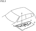
- the wire harness structure 10 is fixed to the roof liner 20, and is assembled to a vehicle interior side which is an inner surface side of the ceiling covering the upper portion of the vehicle interior of the automobile (see FIG. 3 ).
- the wire harness 11 is fixed to the sheet material 12 by covering the wire harness 11 with the sheet material 12 coated with a thermoplastic adhesive to form the wire harness structure 10 (see FIG. 1C ).
- the terminal connector 11c of the wire harness 11 is disposed at a proper position (a position suitable for connecting the terminal connector 11c to a power supply device, various electrical devices, and the like when the roof liner 20 is assembled to the ceiling 20) (see FIG. 1D ).
- the wire harness structure 10 is fixed to the roof liner 20 by pressurizing the bonding portion (required portion) 13 shown in FIG. IE with a pressurizing member.
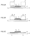
- FIG. 2A to 2C are diagrams for illustrating steps of fixing a wire harness structure 10 to a roof liner 20 in the embodiment of the present invention.
- adhesiveness is generated by warming a required portion by, for example, a heating member 51 (see FIG. 2A ).
- the sheet material 12 is fixed to the roof liner 20 by the thermoplastic adhesive (see FIG. 2C ) by pressurizing the bonding portion 13 of the sheet material 12 with a pressurizing member 52 (see FIG. 2B ) in a state in which adhesiveness is generated.
- the thermoplastic adhesive enters skin of the roof liner 20 to obtain an anchor effect, and firmly bonds the sheet material 12 to the roof liner 20.
- the bonding portion 13 may be formed only in a range depending on needs such as a wide width and a spot. In addition, it is not necessary to make the sheet material 12 wider than necessary, but it is also possible to form the sheet material 12 in a necessary minimum range. Further, when the wire harness structure 10 is fixed to the roof liner 20, the sheet material 12 may be fixed to the roof liner 20 via the thermoplastic adhesive by pressurizing while warming the bonding portion 13 using a pressurizing member capable of heating.
- the wire harness structure 10 in which the wire harness 11 is fixed to the sheet material 12 in advance is formed, and by fixing the wire harness structure 10 to the roof liner 20 via the thermoplastic adhesive, it is possible to easily fix the wire harness 11 to the roof liner 20 without performing operation which takes time and effort such as wiring along a path while loosening entanglement of the wire harness 11. Therefore, the wiring operation on an assembly line can be simplified, and assembly operation time can be shortened. Further, the wire harness 11 can be fixed to the roof liner 20 without requiring a special structure such as processing of an attachment side or a fixing member such as a clip.
- the sheet material 12 to which the wire harness 11 is assembled and the roof liner 20 are fixed by the anchor effect of the adhesive (thermoplastic adhesive), certain fixation is possible, and quality is stabilized. Further, a bonding surface (bonding portion 13) can be adjusted by a volume of a circuit, and efficient bonding is possible. Further, the method of fixing a wire harness of the present embodiment is suitable for fixing a narrow portion since there is no need for a component for fixing the wire harness.
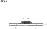
- the wire harness 11 is fixed to the sheet material 12 by sandwiching the wire harness 11 between the two sheet materials 12, but a method of attaching or bonding the wire harness 11 to one sheet material 12 (see FIG. 4 ) and the like can also be applied.
- a thermoplastic adhesive is applied to the same surface as a surface to which the wire harness 11 of the sheet material 12 is fixed.
Landscapes
- Engineering & Computer Science (AREA)
- Mechanical Engineering (AREA)
- Architecture (AREA)
- Civil Engineering (AREA)
- Structural Engineering (AREA)
- Installation Of Indoor Wiring (AREA)
- Vehicle Interior And Exterior Ornaments, Soundproofing, And Insulation (AREA)
Applications Claiming Priority (1)
| Application Number | Priority Date | Filing Date | Title |
|---|---|---|---|
| JP2018173258A JP6842448B2 (ja) | 2018-09-18 | 2018-09-18 | ワイヤハーネスの固定方法 |
Publications (2)
| Publication Number | Publication Date |
|---|---|
| EP3626541A1 true EP3626541A1 (fr) | 2020-03-25 |
| EP3626541B1 EP3626541B1 (fr) | 2021-11-24 |
Family
ID=67928693
Family Applications (1)
| Application Number | Title | Priority Date | Filing Date |
|---|---|---|---|
| EP19196677.9A Active EP3626541B1 (fr) | 2018-09-18 | 2019-09-11 | Procédé de fixation de faisceau de câbles |
Country Status (4)
| Country | Link |
|---|---|
| US (1) | US11611199B2 (fr) |
| EP (1) | EP3626541B1 (fr) |
| JP (1) | JP6842448B2 (fr) |
| CN (1) | CN110901558B (fr) |
Cited By (2)
| Publication number | Priority date | Publication date | Assignee | Title |
|---|---|---|---|---|
| CN113492775A (zh) * | 2020-04-07 | 2021-10-12 | 矢崎总业株式会社 | 线束的布线结构和线束 |
| EP3892500A1 (fr) * | 2020-04-07 | 2021-10-13 | Yazaki Corporation | Structure de câblage d'un faisceau de câbles et faisceau de câbles |
Families Citing this family (10)
| Publication number | Priority date | Publication date | Assignee | Title |
|---|---|---|---|---|
| JP7184019B2 (ja) * | 2019-11-14 | 2022-12-06 | 住友電装株式会社 | 配線部材 |
| JP7465139B2 (ja) * | 2020-04-22 | 2024-04-10 | リンテック株式会社 | ハーネス固定用テープおよびハーネス固定用テープを用いた固定方法 |
| JP7622465B2 (ja) * | 2021-02-24 | 2025-01-28 | 株式会社オートネットワーク技術研究所 | 配線部材付き被着体 |
| JP7639439B2 (ja) * | 2021-03-23 | 2025-03-05 | 株式会社オートネットワーク技術研究所 | 配線部材付き被着体 |
| JP7650709B2 (ja) * | 2021-04-15 | 2025-03-25 | 三菱電機株式会社 | 固定構造及び固定対象物の固定方法 |
| JP7683456B2 (ja) * | 2021-10-28 | 2025-05-27 | 株式会社オートネットワーク技術研究所 | 配線部材付き被着体及び配線部材付き被着体の製造方法 |
| CA3244081A1 (fr) * | 2022-03-30 | 2023-10-05 | Bmic Llc | Systèmes et appareils pour une fixation de toiture électronique modulaire et procédés d'utilisation correspondants |
| DE102022004888A1 (de) | 2022-12-22 | 2024-04-25 | Mercedes-Benz Group AG | Hilfsvorrichtung zur Überkopfmontage eines Leitungssatzes in einem Kraftfahrzeug, Montagesatz, Kraftfahrzeug sowie Verfahren zur Überkopfmontage eines Leitungssatzes in einem Kraftfahrzeug |
| JPWO2024204086A1 (fr) * | 2023-03-28 | 2024-10-03 | ||
| JP7817230B2 (ja) * | 2023-12-20 | 2026-02-18 | 矢崎総業株式会社 | ワイヤハーネス組付体 |
Citations (19)
| Publication number | Priority date | Publication date | Assignee | Title |
|---|---|---|---|---|
| DE19649972A1 (de) * | 1996-11-22 | 1998-05-28 | Siemens Ag | Verfahren zur Herstellung eines Leitungssatzes für Kraftfahrzeuge |
| JP2000264249A (ja) | 1999-03-15 | 2000-09-26 | Howa Seni Kogyo Kk | ワイヤーハーネスの端末部固定構造 |
| JP2000264137A (ja) | 1999-03-15 | 2000-09-26 | Howa Seni Kogyo Kk | 自動車天井へのワイヤーハーネス固着構造 |
| JP2000335329A (ja) | 1999-05-31 | 2000-12-05 | Sumitomo Wiring Syst Ltd | 自動車ルーフ部のワイヤハーネス配索構造 |
| JP2002067829A (ja) | 2000-08-30 | 2002-03-08 | Araco Corp | 車両用内装部材における配線構造及び内装部材の成形方法 |
| JP2002249004A (ja) | 2001-02-22 | 2002-09-03 | Yazaki Corp | 溶融部材およびワイヤハーネスの配策方法 |
| JP2004074954A (ja) | 2002-08-20 | 2004-03-11 | Kasai Kogyo Co Ltd | ハーネスの固定構造 |
| JP2006076531A (ja) | 2004-09-13 | 2006-03-23 | Kasai Kogyo Co Ltd | 成形天井におけるハーネス保持構造 |
| JP2006096856A (ja) | 2004-09-29 | 2006-04-13 | Dainippon Ink & Chem Inc | 自動車用ワイヤーハーネス固定用粘着シート及び自動車用成型部品 |
| JP2006205812A (ja) * | 2005-01-26 | 2006-08-10 | Yazaki Corp | 回路体およびその製造方法と製造装置 |
| JP2010259297A (ja) * | 2009-04-28 | 2010-11-11 | Sumitomo Wiring Syst Ltd | ワイヤハーネス・モジュール、該ワイヤハーネス・モジュールの製造方法および車体取付構造 |
| JP2012099301A (ja) | 2010-11-01 | 2012-05-24 | Auto Network Gijutsu Kenkyusho:Kk | ワイヤハーネス及びその製造方法 |
| JP2012155991A (ja) | 2011-01-26 | 2012-08-16 | Auto Network Gijutsu Kenkyusho:Kk | ワイヤハーネス |
| JP2012157158A (ja) | 2011-01-26 | 2012-08-16 | Auto Network Gijutsu Kenkyusho:Kk | ワイヤハーネス |
| WO2014050196A1 (fr) * | 2012-09-26 | 2014-04-03 | 住友電装株式会社 | Faisceau de câbles |
| JP2014136536A (ja) | 2013-01-18 | 2014-07-28 | Sumitomo Wiring Syst Ltd | 自動車ルーフ部のワイヤハーネスの配索構造および自動車ルーフ部用のワイヤハーネス |
| JP2015090783A (ja) | 2013-11-05 | 2015-05-11 | 住友電装株式会社 | ワイヤハーネス |
| US20170327060A1 (en) * | 2014-12-16 | 2017-11-16 | Sumitomo Wiring Systems, Ltd. | Wire harness |
| JP2018090229A (ja) | 2016-11-29 | 2018-06-14 | 矢崎総業株式会社 | ワイヤハーネス組付体及び車両 |
Family Cites Families (13)
| Publication number | Priority date | Publication date | Assignee | Title |
|---|---|---|---|---|
| JPS5942301Y2 (ja) * | 1976-07-15 | 1984-12-10 | 日産自動車株式会社 | 段ボ−ル製ル−フトリム |
| JPH11308741A (ja) * | 1998-04-24 | 1999-11-05 | Yazaki Corp | 電線の配索方法 |
| GB0015098D0 (en) * | 2000-06-20 | 2000-08-09 | Yazaki Europe Ltd | Vehicle panel |
| JP2002112440A (ja) * | 2000-09-29 | 2002-04-12 | Yazaki Corp | フラットワイヤハーネスの固定構造及び該フラットワイヤハーネスの固定方法 |
| DE60139516D1 (de) * | 2000-10-25 | 2009-09-17 | Velcro Ind | Verfahren zur kontinuierlichen Herstellung eines elektrischen Kabels |
| CN1704233A (zh) * | 2004-05-28 | 2005-12-07 | 翰柏企业股份有限公司 | 橡胶基材及其制造方法 |
| DE102005037663A1 (de) * | 2005-08-05 | 2007-02-08 | Tesa Ag | Verwendung eines Klebebandes mit einem Träger aus einem Spinnvlies, der einseitig mit einem druckempfindlichen Kleber zumindest partiell beschichtet ist |
| JP2012140496A (ja) * | 2010-12-28 | 2012-07-26 | Nitto Denko Corp | 束ね材、束ね方法および束ね構造体 |
| JP2012245925A (ja) * | 2011-05-30 | 2012-12-13 | Howa Textile Industry Co Ltd | 自動車用ボディーアンダーカバー |
| JP2016154430A (ja) * | 2015-02-12 | 2016-08-25 | 株式会社オートネットワーク技術研究所 | 外装ワイヤーハーネス |
| JP6562034B2 (ja) * | 2017-05-12 | 2019-08-21 | 株式会社オートネットワーク技術研究所 | ワイヤーハーネスの固定構造 |
| CN107695214A (zh) | 2017-09-30 | 2018-02-16 | 西安石油大学 | 一种轻量化板材的激光加热平底无铆连接成形装置及工艺 |
| JP7193497B2 (ja) * | 2020-04-07 | 2022-12-20 | 矢崎総業株式会社 | ワイヤハーネスの配索構造およびワイヤハーネス |
-
2018
- 2018-09-18 JP JP2018173258A patent/JP6842448B2/ja active Active
-
2019
- 2019-09-11 EP EP19196677.9A patent/EP3626541B1/fr active Active
- 2019-09-11 US US16/567,288 patent/US11611199B2/en active Active
- 2019-09-17 CN CN201910877142.9A patent/CN110901558B/zh active Active
Patent Citations (19)
| Publication number | Priority date | Publication date | Assignee | Title |
|---|---|---|---|---|
| DE19649972A1 (de) * | 1996-11-22 | 1998-05-28 | Siemens Ag | Verfahren zur Herstellung eines Leitungssatzes für Kraftfahrzeuge |
| JP2000264249A (ja) | 1999-03-15 | 2000-09-26 | Howa Seni Kogyo Kk | ワイヤーハーネスの端末部固定構造 |
| JP2000264137A (ja) | 1999-03-15 | 2000-09-26 | Howa Seni Kogyo Kk | 自動車天井へのワイヤーハーネス固着構造 |
| JP2000335329A (ja) | 1999-05-31 | 2000-12-05 | Sumitomo Wiring Syst Ltd | 自動車ルーフ部のワイヤハーネス配索構造 |
| JP2002067829A (ja) | 2000-08-30 | 2002-03-08 | Araco Corp | 車両用内装部材における配線構造及び内装部材の成形方法 |
| JP2002249004A (ja) | 2001-02-22 | 2002-09-03 | Yazaki Corp | 溶融部材およびワイヤハーネスの配策方法 |
| JP2004074954A (ja) | 2002-08-20 | 2004-03-11 | Kasai Kogyo Co Ltd | ハーネスの固定構造 |
| JP2006076531A (ja) | 2004-09-13 | 2006-03-23 | Kasai Kogyo Co Ltd | 成形天井におけるハーネス保持構造 |
| JP2006096856A (ja) | 2004-09-29 | 2006-04-13 | Dainippon Ink & Chem Inc | 自動車用ワイヤーハーネス固定用粘着シート及び自動車用成型部品 |
| JP2006205812A (ja) * | 2005-01-26 | 2006-08-10 | Yazaki Corp | 回路体およびその製造方法と製造装置 |
| JP2010259297A (ja) * | 2009-04-28 | 2010-11-11 | Sumitomo Wiring Syst Ltd | ワイヤハーネス・モジュール、該ワイヤハーネス・モジュールの製造方法および車体取付構造 |
| JP2012099301A (ja) | 2010-11-01 | 2012-05-24 | Auto Network Gijutsu Kenkyusho:Kk | ワイヤハーネス及びその製造方法 |
| JP2012155991A (ja) | 2011-01-26 | 2012-08-16 | Auto Network Gijutsu Kenkyusho:Kk | ワイヤハーネス |
| JP2012157158A (ja) | 2011-01-26 | 2012-08-16 | Auto Network Gijutsu Kenkyusho:Kk | ワイヤハーネス |
| WO2014050196A1 (fr) * | 2012-09-26 | 2014-04-03 | 住友電装株式会社 | Faisceau de câbles |
| JP2014136536A (ja) | 2013-01-18 | 2014-07-28 | Sumitomo Wiring Syst Ltd | 自動車ルーフ部のワイヤハーネスの配索構造および自動車ルーフ部用のワイヤハーネス |
| JP2015090783A (ja) | 2013-11-05 | 2015-05-11 | 住友電装株式会社 | ワイヤハーネス |
| US20170327060A1 (en) * | 2014-12-16 | 2017-11-16 | Sumitomo Wiring Systems, Ltd. | Wire harness |
| JP2018090229A (ja) | 2016-11-29 | 2018-06-14 | 矢崎総業株式会社 | ワイヤハーネス組付体及び車両 |
Cited By (6)
| Publication number | Priority date | Publication date | Assignee | Title |
|---|---|---|---|---|
| CN113492775A (zh) * | 2020-04-07 | 2021-10-12 | 矢崎总业株式会社 | 线束的布线结构和线束 |
| EP3892500A1 (fr) * | 2020-04-07 | 2021-10-13 | Yazaki Corporation | Structure de câblage d'un faisceau de câbles et faisceau de câbles |
| EP3892499A1 (fr) * | 2020-04-07 | 2021-10-13 | Yazaki Corporation | Structure de câblage d'un faisceau de câbles et faisceau de câbles |
| US11370370B2 (en) | 2020-04-07 | 2022-06-28 | Yazaki Corporation | Wiring structure of wire harness and wire harness |
| US11414030B2 (en) | 2020-04-07 | 2022-08-16 | Yazaki Corporation | Wiring structure of wire harness and wire harness |
| CN113492775B (zh) * | 2020-04-07 | 2024-01-30 | 矢崎总业株式会社 | 线束的布线结构和线束 |
Also Published As
| Publication number | Publication date |
|---|---|
| EP3626541B1 (fr) | 2021-11-24 |
| US20200091689A1 (en) | 2020-03-19 |
| JP6842448B2 (ja) | 2021-03-17 |
| US11611199B2 (en) | 2023-03-21 |
| CN110901558A (zh) | 2020-03-24 |
| JP2020044900A (ja) | 2020-03-26 |
| CN110901558B (zh) | 2023-05-16 |
Similar Documents
| Publication | Publication Date | Title |
|---|---|---|
| EP3626541B1 (fr) | Procédé de fixation de faisceau de câbles | |
| EP2919341A1 (fr) | Faisceau de câbles | |
| JP2019079828A (ja) | ワイヤーハーネス | |
| EP3539830A1 (fr) | Faisceau de câbles et procédé de fabrication d'un matériau en feuille comprenant un faisceau de câbles | |
| JP2017511957A (ja) | 電気ケーブルおよび電気ケーブル束を製造するための方法 | |
| JP2015090783A (ja) | ワイヤハーネス | |
| JPH117856A (ja) | ワイヤハーネスへの保護材の外装構造 | |
| JP2000264137A (ja) | 自動車天井へのワイヤーハーネス固着構造 | |
| KR20170128643A (ko) | 자동차용 케이블 고정구 | |
| JP6911717B2 (ja) | ワイヤーハーネス | |
| JP2015088397A (ja) | 車両用のワイヤハーネスおよび該ワイヤハーネスの製造方法 | |
| US20150222101A1 (en) | Wire harness, wire harness manufacturing method and protective member | |
| JP2014068521A (ja) | ワイヤーハーネス | |
| JP2750271B2 (ja) | コードクランプの固定構造 | |
| JP7424177B2 (ja) | 配線部材 | |
| JP2015074365A (ja) | 車両用シート材モジュール | |
| JP6325788B2 (ja) | ワイヤハーネスの組付け方法、及び、組付け構造 | |
| JP2021082382A (ja) | 配線部材 | |
| JP7184019B2 (ja) | 配線部材 | |
| JPH10136541A (ja) | ワイヤーハーネスの車体パネル取付構造 | |
| US12126156B2 (en) | Fixing structure of wiring member, and wiring member with joint member | |
| US12009124B2 (en) | Fixing structure of wiring member, and wiring member with heat generation layer | |
| JP2010252424A (ja) | ワイヤハーネス | |
| CN114365237B (zh) | 配线构件的固定构造以及配线构件 | |
| JP2000264249A (ja) | ワイヤーハーネスの端末部固定構造 |
Legal Events
| Date | Code | Title | Description |
|---|---|---|---|
| PUAI | Public reference made under article 153(3) epc to a published international application that has entered the european phase |
Free format text: ORIGINAL CODE: 0009012 |
|
| STAA | Information on the status of an ep patent application or granted ep patent |
Free format text: STATUS: REQUEST FOR EXAMINATION WAS MADE |
|
| 17P | Request for examination filed |
Effective date: 20190911 |
|
| AK | Designated contracting states |
Kind code of ref document: A1 Designated state(s): AL AT BE BG CH CY CZ DE DK EE ES FI FR GB GR HR HU IE IS IT LI LT LU LV MC MK MT NL NO PL PT RO RS SE SI SK SM TR |
|
| AX | Request for extension of the european patent |
Extension state: BA ME |
|
| GRAP | Despatch of communication of intention to grant a patent |
Free format text: ORIGINAL CODE: EPIDOSNIGR1 |
|
| STAA | Information on the status of an ep patent application or granted ep patent |
Free format text: STATUS: GRANT OF PATENT IS INTENDED |
|
| INTG | Intention to grant announced |
Effective date: 20210903 |
|
| GRAS | Grant fee paid |
Free format text: ORIGINAL CODE: EPIDOSNIGR3 |
|
| GRAA | (expected) grant |
Free format text: ORIGINAL CODE: 0009210 |
|
| STAA | Information on the status of an ep patent application or granted ep patent |
Free format text: STATUS: THE PATENT HAS BEEN GRANTED |
|
| AK | Designated contracting states |
Kind code of ref document: B1 Designated state(s): AL AT BE BG CH CY CZ DE DK EE ES FI FR GB GR HR HU IE IS IT LI LT LU LV MC MK MT NL NO PL PT RO RS SE SI SK SM TR |
|
| REG | Reference to a national code |
Ref country code: GB Ref legal event code: FG4D |
|
| REG | Reference to a national code |
Ref country code: DE Ref legal event code: R096 Ref document number: 602019009488 Country of ref document: DE |
|
| REG | Reference to a national code |
Ref country code: AT Ref legal event code: REF Ref document number: 1449638 Country of ref document: AT Kind code of ref document: T Effective date: 20211215 |
|
| REG | Reference to a national code |
Ref country code: IE Ref legal event code: FG4D |
|
| REG | Reference to a national code |
Ref country code: LT Ref legal event code: MG9D |
|
| REG | Reference to a national code |
Ref country code: NL Ref legal event code: MP Effective date: 20211124 |
|
| REG | Reference to a national code |
Ref country code: AT Ref legal event code: MK05 Ref document number: 1449638 Country of ref document: AT Kind code of ref document: T Effective date: 20211124 |
|
| PG25 | Lapsed in a contracting state [announced via postgrant information from national office to epo] |
Ref country code: RS Free format text: LAPSE BECAUSE OF FAILURE TO SUBMIT A TRANSLATION OF THE DESCRIPTION OR TO PAY THE FEE WITHIN THE PRESCRIBED TIME-LIMIT Effective date: 20211124 Ref country code: LT Free format text: LAPSE BECAUSE OF FAILURE TO SUBMIT A TRANSLATION OF THE DESCRIPTION OR TO PAY THE FEE WITHIN THE PRESCRIBED TIME-LIMIT Effective date: 20211124 Ref country code: FI Free format text: LAPSE BECAUSE OF FAILURE TO SUBMIT A TRANSLATION OF THE DESCRIPTION OR TO PAY THE FEE WITHIN THE PRESCRIBED TIME-LIMIT Effective date: 20211124 Ref country code: BG Free format text: LAPSE BECAUSE OF FAILURE TO SUBMIT A TRANSLATION OF THE DESCRIPTION OR TO PAY THE FEE WITHIN THE PRESCRIBED TIME-LIMIT Effective date: 20220224 Ref country code: AT Free format text: LAPSE BECAUSE OF FAILURE TO SUBMIT A TRANSLATION OF THE DESCRIPTION OR TO PAY THE FEE WITHIN THE PRESCRIBED TIME-LIMIT Effective date: 20211124 |
|
| PG25 | Lapsed in a contracting state [announced via postgrant information from national office to epo] |
Ref country code: IS Free format text: LAPSE BECAUSE OF FAILURE TO SUBMIT A TRANSLATION OF THE DESCRIPTION OR TO PAY THE FEE WITHIN THE PRESCRIBED TIME-LIMIT Effective date: 20220324 Ref country code: SE Free format text: LAPSE BECAUSE OF FAILURE TO SUBMIT A TRANSLATION OF THE DESCRIPTION OR TO PAY THE FEE WITHIN THE PRESCRIBED TIME-LIMIT Effective date: 20211124 Ref country code: PT Free format text: LAPSE BECAUSE OF FAILURE TO SUBMIT A TRANSLATION OF THE DESCRIPTION OR TO PAY THE FEE WITHIN THE PRESCRIBED TIME-LIMIT Effective date: 20220324 Ref country code: PL Free format text: LAPSE BECAUSE OF FAILURE TO SUBMIT A TRANSLATION OF THE DESCRIPTION OR TO PAY THE FEE WITHIN THE PRESCRIBED TIME-LIMIT Effective date: 20211124 Ref country code: NO Free format text: LAPSE BECAUSE OF FAILURE TO SUBMIT A TRANSLATION OF THE DESCRIPTION OR TO PAY THE FEE WITHIN THE PRESCRIBED TIME-LIMIT Effective date: 20220224 Ref country code: NL Free format text: LAPSE BECAUSE OF FAILURE TO SUBMIT A TRANSLATION OF THE DESCRIPTION OR TO PAY THE FEE WITHIN THE PRESCRIBED TIME-LIMIT Effective date: 20211124 Ref country code: LV Free format text: LAPSE BECAUSE OF FAILURE TO SUBMIT A TRANSLATION OF THE DESCRIPTION OR TO PAY THE FEE WITHIN THE PRESCRIBED TIME-LIMIT Effective date: 20211124 Ref country code: HR Free format text: LAPSE BECAUSE OF FAILURE TO SUBMIT A TRANSLATION OF THE DESCRIPTION OR TO PAY THE FEE WITHIN THE PRESCRIBED TIME-LIMIT Effective date: 20211124 Ref country code: GR Free format text: LAPSE BECAUSE OF FAILURE TO SUBMIT A TRANSLATION OF THE DESCRIPTION OR TO PAY THE FEE WITHIN THE PRESCRIBED TIME-LIMIT Effective date: 20220225 Ref country code: ES Free format text: LAPSE BECAUSE OF FAILURE TO SUBMIT A TRANSLATION OF THE DESCRIPTION OR TO PAY THE FEE WITHIN THE PRESCRIBED TIME-LIMIT Effective date: 20211124 |
|
| PG25 | Lapsed in a contracting state [announced via postgrant information from national office to epo] |
Ref country code: SM Free format text: LAPSE BECAUSE OF FAILURE TO SUBMIT A TRANSLATION OF THE DESCRIPTION OR TO PAY THE FEE WITHIN THE PRESCRIBED TIME-LIMIT Effective date: 20211124 Ref country code: SK Free format text: LAPSE BECAUSE OF FAILURE TO SUBMIT A TRANSLATION OF THE DESCRIPTION OR TO PAY THE FEE WITHIN THE PRESCRIBED TIME-LIMIT Effective date: 20211124 Ref country code: RO Free format text: LAPSE BECAUSE OF FAILURE TO SUBMIT A TRANSLATION OF THE DESCRIPTION OR TO PAY THE FEE WITHIN THE PRESCRIBED TIME-LIMIT Effective date: 20211124 Ref country code: EE Free format text: LAPSE BECAUSE OF FAILURE TO SUBMIT A TRANSLATION OF THE DESCRIPTION OR TO PAY THE FEE WITHIN THE PRESCRIBED TIME-LIMIT Effective date: 20211124 Ref country code: DK Free format text: LAPSE BECAUSE OF FAILURE TO SUBMIT A TRANSLATION OF THE DESCRIPTION OR TO PAY THE FEE WITHIN THE PRESCRIBED TIME-LIMIT Effective date: 20211124 Ref country code: CZ Free format text: LAPSE BECAUSE OF FAILURE TO SUBMIT A TRANSLATION OF THE DESCRIPTION OR TO PAY THE FEE WITHIN THE PRESCRIBED TIME-LIMIT Effective date: 20211124 |
|
| REG | Reference to a national code |
Ref country code: DE Ref legal event code: R097 Ref document number: 602019009488 Country of ref document: DE |
|
| PLBE | No opposition filed within time limit |
Free format text: ORIGINAL CODE: 0009261 |
|
| STAA | Information on the status of an ep patent application or granted ep patent |
Free format text: STATUS: NO OPPOSITION FILED WITHIN TIME LIMIT |
|
| PG25 | Lapsed in a contracting state [announced via postgrant information from national office to epo] |
Ref country code: AL Free format text: LAPSE BECAUSE OF FAILURE TO SUBMIT A TRANSLATION OF THE DESCRIPTION OR TO PAY THE FEE WITHIN THE PRESCRIBED TIME-LIMIT Effective date: 20211124 |
|
| 26N | No opposition filed |
Effective date: 20220825 |
|
| PG25 | Lapsed in a contracting state [announced via postgrant information from national office to epo] |
Ref country code: SI Free format text: LAPSE BECAUSE OF FAILURE TO SUBMIT A TRANSLATION OF THE DESCRIPTION OR TO PAY THE FEE WITHIN THE PRESCRIBED TIME-LIMIT Effective date: 20211124 |
|
| PG25 | Lapsed in a contracting state [announced via postgrant information from national office to epo] |
Ref country code: MC Free format text: LAPSE BECAUSE OF FAILURE TO SUBMIT A TRANSLATION OF THE DESCRIPTION OR TO PAY THE FEE WITHIN THE PRESCRIBED TIME-LIMIT Effective date: 20211124 |
|
| REG | Reference to a national code |
Ref country code: CH Ref legal event code: PL |
|
| REG | Reference to a national code |
Ref country code: BE Ref legal event code: MM Effective date: 20220930 |
|
| PG25 | Lapsed in a contracting state [announced via postgrant information from national office to epo] |
Ref country code: IT Free format text: LAPSE BECAUSE OF FAILURE TO SUBMIT A TRANSLATION OF THE DESCRIPTION OR TO PAY THE FEE WITHIN THE PRESCRIBED TIME-LIMIT Effective date: 20211124 |
|
| PG25 | Lapsed in a contracting state [announced via postgrant information from national office to epo] |
Ref country code: LU Free format text: LAPSE BECAUSE OF NON-PAYMENT OF DUE FEES Effective date: 20220911 |
|
| PG25 | Lapsed in a contracting state [announced via postgrant information from national office to epo] |
Ref country code: LI Free format text: LAPSE BECAUSE OF NON-PAYMENT OF DUE FEES Effective date: 20220930 Ref country code: IE Free format text: LAPSE BECAUSE OF NON-PAYMENT OF DUE FEES Effective date: 20220911 Ref country code: FR Free format text: LAPSE BECAUSE OF NON-PAYMENT OF DUE FEES Effective date: 20220930 Ref country code: CH Free format text: LAPSE BECAUSE OF NON-PAYMENT OF DUE FEES Effective date: 20220930 |
|
| PG25 | Lapsed in a contracting state [announced via postgrant information from national office to epo] |
Ref country code: BE Free format text: LAPSE BECAUSE OF NON-PAYMENT OF DUE FEES Effective date: 20220930 |
|
| PG25 | Lapsed in a contracting state [announced via postgrant information from national office to epo] |
Ref country code: HU Free format text: LAPSE BECAUSE OF FAILURE TO SUBMIT A TRANSLATION OF THE DESCRIPTION OR TO PAY THE FEE WITHIN THE PRESCRIBED TIME-LIMIT; INVALID AB INITIO Effective date: 20190911 |
|
| PG25 | Lapsed in a contracting state [announced via postgrant information from national office to epo] |
Ref country code: CY Free format text: LAPSE BECAUSE OF FAILURE TO SUBMIT A TRANSLATION OF THE DESCRIPTION OR TO PAY THE FEE WITHIN THE PRESCRIBED TIME-LIMIT Effective date: 20211124 |
|
| GBPC | Gb: european patent ceased through non-payment of renewal fee |
Effective date: 20230911 |
|
| PG25 | Lapsed in a contracting state [announced via postgrant information from national office to epo] |
Ref country code: MK Free format text: LAPSE BECAUSE OF FAILURE TO SUBMIT A TRANSLATION OF THE DESCRIPTION OR TO PAY THE FEE WITHIN THE PRESCRIBED TIME-LIMIT Effective date: 20211124 |
|
| PG25 | Lapsed in a contracting state [announced via postgrant information from national office to epo] |
Ref country code: TR Free format text: LAPSE BECAUSE OF FAILURE TO SUBMIT A TRANSLATION OF THE DESCRIPTION OR TO PAY THE FEE WITHIN THE PRESCRIBED TIME-LIMIT Effective date: 20211124 |
|
| PG25 | Lapsed in a contracting state [announced via postgrant information from national office to epo] |
Ref country code: GB Free format text: LAPSE BECAUSE OF NON-PAYMENT OF DUE FEES Effective date: 20230911 |
|
| PG25 | Lapsed in a contracting state [announced via postgrant information from national office to epo] |
Ref country code: GB Free format text: LAPSE BECAUSE OF NON-PAYMENT OF DUE FEES Effective date: 20230911 |
|
| PG25 | Lapsed in a contracting state [announced via postgrant information from national office to epo] |
Ref country code: MT Free format text: LAPSE BECAUSE OF FAILURE TO SUBMIT A TRANSLATION OF THE DESCRIPTION OR TO PAY THE FEE WITHIN THE PRESCRIBED TIME-LIMIT Effective date: 20211124 |
|
| PGFP | Annual fee paid to national office [announced via postgrant information from national office to epo] |
Ref country code: DE Payment date: 20250730 Year of fee payment: 7 |