EP3628525A1 - Véhicule automobile doté d'un entraînement auxiliaire pour un essieu dirigeable - Google Patents
Véhicule automobile doté d'un entraînement auxiliaire pour un essieu dirigeable Download PDFInfo
- Publication number
- EP3628525A1 EP3628525A1 EP19199616.4A EP19199616A EP3628525A1 EP 3628525 A1 EP3628525 A1 EP 3628525A1 EP 19199616 A EP19199616 A EP 19199616A EP 3628525 A1 EP3628525 A1 EP 3628525A1
- Authority
- EP
- European Patent Office
- Prior art keywords
- axle
- drive
- differential
- motor
- transmission
- Prior art date
- Legal status (The legal status is an assumption and is not a legal conclusion. Google has not performed a legal analysis and makes no representation as to the accuracy of the status listed.)
- Granted
Links
Images

Classifications
-
- B—PERFORMING OPERATIONS; TRANSPORTING
- B60—VEHICLES IN GENERAL
- B60K—ARRANGEMENT OR MOUNTING OF PROPULSION UNITS OR OF TRANSMISSIONS IN VEHICLES; ARRANGEMENT OR MOUNTING OF PLURAL DIVERSE PRIME-MOVERS IN VEHICLES; AUXILIARY DRIVES FOR VEHICLES; INSTRUMENTATION OR DASHBOARDS FOR VEHICLES; ARRANGEMENTS IN CONNECTION WITH COOLING, AIR INTAKE, GAS EXHAUST OR FUEL SUPPLY OF PROPULSION UNITS IN VEHICLES
- B60K17/00—Arrangement or mounting of transmissions in vehicles
- B60K17/34—Arrangement or mounting of transmissions in vehicles for driving both front and rear wheels, e.g. four wheel drive vehicles
- B60K17/354—Arrangement or mounting of transmissions in vehicles for driving both front and rear wheels, e.g. four wheel drive vehicles having separate mechanical assemblies for transmitting drive to the front or to the rear wheels or set of wheels
-
- B—PERFORMING OPERATIONS; TRANSPORTING
- B60—VEHICLES IN GENERAL
- B60K—ARRANGEMENT OR MOUNTING OF PROPULSION UNITS OR OF TRANSMISSIONS IN VEHICLES; ARRANGEMENT OR MOUNTING OF PLURAL DIVERSE PRIME-MOVERS IN VEHICLES; AUXILIARY DRIVES FOR VEHICLES; INSTRUMENTATION OR DASHBOARDS FOR VEHICLES; ARRANGEMENTS IN CONNECTION WITH COOLING, AIR INTAKE, GAS EXHAUST OR FUEL SUPPLY OF PROPULSION UNITS IN VEHICLES
- B60K17/00—Arrangement or mounting of transmissions in vehicles
- B60K17/34—Arrangement or mounting of transmissions in vehicles for driving both front and rear wheels, e.g. four wheel drive vehicles
- B60K17/356—Arrangement or mounting of transmissions in vehicles for driving both front and rear wheels, e.g. four wheel drive vehicles having fluid or electric motor, for driving one or more wheels
-
- B—PERFORMING OPERATIONS; TRANSPORTING
- B60—VEHICLES IN GENERAL
- B60Y—INDEXING SCHEME RELATING TO ASPECTS CROSS-CUTTING VEHICLE TECHNOLOGY
- B60Y2200/00—Type of vehicle
- B60Y2200/10—Road Vehicles
- B60Y2200/14—Trucks; Load vehicles, Busses
- B60Y2200/141—Light trucks
-
- B—PERFORMING OPERATIONS; TRANSPORTING
- B60—VEHICLES IN GENERAL
- B60Y—INDEXING SCHEME RELATING TO ASPECTS CROSS-CUTTING VEHICLE TECHNOLOGY
- B60Y2200/00—Type of vehicle
- B60Y2200/10—Road Vehicles
- B60Y2200/14—Trucks; Load vehicles, Busses
- B60Y2200/142—Heavy duty trucks
Definitions
- the invention relates to a motor vehicle with an auxiliary drive for a steerable axle.
- EP 1 886 861 A2 a drive system comprising a conventional, mechanical rear axle driven via a drive shaft, the drive shaft being operatively connected to an axle differential of the rear axle.
- the drive system further comprises two front wheels 1 which can be driven by hydraulic wheel motors RM and which are arranged in a steerable manner on a front axle 3.
- the two RM wheel motors are integrated in a closed hydrostatic circuit.
- a main pump is mechanically driven via the mechanical drive train of the vehicle.
- the two wheel motors RM can be activated by a control valve. This enables considerable weight and efficiency advantages to be achieved compared to vehicles with permanent all-wheel drive, in particular in vehicles in which all-wheel drive is only required for a small part of the actual driving distance.
- Light vehicles are characterized by a rigid axle.
- Light vehicles in particular also commercial vehicles with a low payload, are characterized in particular by a single wheel suspension in the steering axle. Contrary to a continuous axle body of a rigid axle, which is connected to the frame / body of the vehicle via spring, damping and guide elements, much lighter and more delicate components are used for the independent wheel suspension.
- Such light vehicles with independent suspension usually have two, in some cases also three axles.
- the drive of these vehicles provides that at least one axle is driven by a mechanical drive train. This can be either the front axle or the rear axle.
- a mechanical drive train This can be either the front axle or the rear axle.
- Such vehicles with all-wheel drive are also known in practice.
- the drive power is transferred permanently or optionally to all axes. It is known from practice that the distribution of the drive force takes place mechanically via transfer cases and / or clutches and shafts. The disadvantage of this is that an assigned drive shaft along the vehicle axis is required for this. This also results in restrictions regarding the driving level.
- the hydrostatically driven wheel motors known from the prior art are generally disadvantageous for vehicles with independent wheel suspension. For reasons of driving dynamics, it is desirable to have the lowest possible unsprung mass of the wheel, which would be impaired by the comparatively heavy hydraulic wheel motors. Furthermore, the laying of hydraulic lines between the wheel part and the vehicle body is associated with disadvantages, since there is generally very little installation space available.
- the object of the invention is to provide an improved vehicle with which disadvantages of conventional technology can be avoided.
- the object of the invention is to provide a drive option in particular also for vehicles with a steerable axle and independent wheel suspension, which enables good driving behavior and takes up little installation space.
- the invention relates to a commercial vehicle with a drivable rigid first axle which can be driven and / or driven via a mechanical drive train which has an internal combustion engine.
- the motor vehicle also includes a steerable second axle with independent wheel suspension.
- the wheels of the second axle are therefore not arranged on a rigid axle, but can perform spring movements independently of one another.
- the first axle is preferably a rear axle and the second axle is a front axle of the vehicle.
- the commercial vehicle has only one rigid axle, ie the rigid first axle is the only rigid axle of the commercial vehicle. It is therefore a light commercial vehicle and not a heavy commercial vehicle which generally has two or more rigid axles.
- the second axle can be driven and / or driven by a hydrostatic auxiliary drive which has a drive motor in the form of a hydraulic motor, also referred to as a hydraulic motor, which distributes its drive power to the wheels of the second axis via a chassis-fixed transmission.
- the transmission can thus be a non-resilient transmission attached to the vehicle frame.
- the transmission can be designed as an axle differential, more preferably as a bevel gear differential.
- the drive motor is thus in particular not a wheel motor or wheel hub motor, but a drive motor which, for. B. can be arranged fixed to the chassis.
- the steerable second axle with independent suspension is therefore not driven the internal combustion engine, but by the auxiliary drive with the drive motor, which is operatively connected to the transmission.
- the drive power of the hydrostatic drive is provided by a power take-off (PTO) of the mechanical drive train, i.e. either via a power take-off provided on the internal combustion engine or via a mechanical transmission on the vehicle transmission, which translates the engine speed to the drive speed, provided power take-off.
- PTO power take-off
- the combination according to the invention of a mechanically driven rigid axle with a hydrostatically driven axle with independent wheel suspension offers the advantage, in particular for light commercial vehicles, that high torque can be transmitted to an additional axle, here the axle with independent wheel suspension, without an assigned drive shaft along it Longitudinal vehicle axis is required. Accordingly, there are also no restrictions with regard to the driving level due to such a drive shaft extending in the longitudinal direction of the vehicle. Furthermore, the mass of the wheel can be kept low, since no wheel hub motor is required, which means that the driving conditions are almost the same as those without the auxiliary drive.
- the drive motor can be arranged coaxially to an output of the axle differential, in particular to a driven shaft of the axle differential. This means that an axis of rotation of a drive shaft of the drive motor or another rotating part of the drive motor for transferring the drive power of the axis of rotation corresponds to a driven shaft of the output of the axle differential.
- a part of the drive motor that is coaxial with an output of the axle differential is operatively connected to a cage of the axle differential of the second axle, in particular connected in a rotationally fixed manner.
- the drive motor can thus drive the cage of the axle differential directly.
- a ring gear and a drive bevel gear coupled to the ring gear for driving the cage of the axle differential can advantageously be dispensed with.
- the drive motor can sit on the shaft of the axle differential.
- the transmission is again designed as an axle differential, the drive motor now not being coaxial with an output or not is arranged coaxially to a driven shaft of the axle differential. Rather, a drive shaft of the drive motor, which is spatially offset from the axis of rotation of the output of the axle differential, is operatively connected to the axle differential of the second axle.
- the drive motor can be arranged spatially independently of the direction of rotation of the axle differential, for example by means of an angular drive or axially parallel, via a mechanical gear.
- This embodiment offers the advantage that no or at least only slight modifications to the inner structure of a conventional axle differential of the second axle are necessary, in order to do this electrically or hydrostatically instead of a drive shaft which is driven by the mechanical drive train, by the drive motor of the auxiliary drive to drive.
- the transmission is a bevel gear differential gear, comprising a ring gear, a pair of axle bevel gears and a pair of differential bevel gears, a drive wheel seated on a drive shaft of the drive motor being in engagement with the ring gear.
- the hydrostatic auxiliary drive can have a hydraulic pump driven by the mechanical drive train, which is connected to the hydraulic motor via a hydraulic working line.
- the hydraulic pump is driven via a power take-off of the mechanical drive train, that is, either via a power take-off provided on the internal combustion engine or via a power take-off provided on the vehicle transmission of the mechanical drive train.
- the drive power for the hydrostatic drive is therefore not transferred mechanically to the axle with independent wheel suspension.
- the hydraulic motor can be designed as a hydraulic motor with a constant or variable absorption volume.
- the hydraulic pump can be designed as a hydraulic pump with a constant or variable absorption volume.
- the hydraulic pump can be flange-mounted, for example, directly or via a coupling on the internal combustion engine or on the transmission.
- the hydraulic working lines for energy transmission between the hydraulic pump and hydraulic motor can be designed as rigid and / or flexible lines.
- the drive components of the hydrostatic drive can be accommodated as required with a small installation space requirement, ie the installation space required is reduced in comparison to a mechanical all-wheel drive in terms of the installation space required considerably.
- a hydrostatic additional drive high drive torques can also be achieved with a comparatively low weight for the components required by the hydrostatic additional drive.
- the hydraulic motor can be connectable and disconnectable from the axle differential of the second axle and / or from the wheel drive shafts of the second axle by means of a clutch or a freewheel.
- a transmission gear with a predetermined reduction or transmission via which the hydraulic motor is operatively connected to the wheels of the second axis, can be provided for adapting the operating range of the hydraulic motor to the wheel speed.
- the hydraulic motor can either be arranged coaxially on the shaft of the axle differential or, via a mechanical transmission, spatially independently of the direction of rotation of the axle differential.
- a differential pin carrying axle bolts can be mounted in the cage of the axle differential, wherein these differential gears mesh with axle shaft gears arranged on wheel drive shafts and these wheels are designed as bevel gears.
- the hydraulic motor can be a radial piston motor, having an outer, fixed cam ring and an inner, circumferential cylinder housing, which is non-rotatably connected to the cage in order to rotate the cage and drive the second axis above it.
- the second axle can have two arranged wheel drive shafts, each of which is non-rotatably connected to a wheel on the wheel side and is operatively connected at its other end to the axle differential or the hydraulic motor.
- the drive motor can be arranged, for example, in a central region of the second axis.
- the commercial vehicle can in particular be a commercial vehicle with a permissible maximum speed of over 60 km / h and / or a commercial vehicle which has a wheel brake device acting on at least two wheels of the commercial vehicle.
- Figure 1 illustrates a drive 1 for a commercial vehicle with two driven axles 2, 4.
- the motor vehicle is designed as a commercial vehicle.
- the vehicle comprises a conventional mechanical drive train for driving a rigid rear axle 2 of the motor vehicle.
- the mechanical drive train comprises an internal combustion engine 9, a transmission 10 and a drive shaft 11 which extends in the direction of the longitudinal axis of the vehicle and transmits the drive power to the rear axle 2.
- the drive shaft 11 is connected to an axle differential 12 of the rear axle 2, via which the drive power is distributed to the two rear wheels 3 essentially in equal parts.
- the vehicle further comprises a steerable front axle 4.
- the wheels 5 of the front axle 4 are fastened to the chassis with an independent wheel suspension 6 in a manner known per se.
- the front axle 4 thus has no rigid axle, i. that is, the front axle 4 does not have a continuous axle body which is connected to the frame / body of the vehicle via spring, damping and guide elements.
- the front axle 4 can be driven by a hydraulic motor 21 (also referred to as a hydraulic motor) of a hydrostatic auxiliary drive 20.
- the hydraulic motor 21 is operatively connected to an axle differential 8 of the front axle 4.
- the two outputs of the axle differential in the form of the two output shafts 8e are each rotatably connected to one of the wheel drive shafts 7a, 7b.
- the axis of rotation R of the outputs or output shafts 8e is shown by the dashed line R.
- the hydraulic motor 21 is integrated in a known hydrostatic circuit, a hydraulic pump 22 being mechanically driven via the mechanical drive train of the vehicle and being hydraulically connected to the hydraulic motor 21 for energy transmission via fluid lines 23, 24.
- One of the fluid lines 23, 24 forms a first branch for forming a flow, while the other fluid line forms the second branch and thus the return of the hydraulic circuit.
- the hydraulic motor and the hydraulic pump 22 can be designed with a constant or variable absorption volume.
- the hydraulic pump can be connected via a clutch 14 and a power take-off shaft 13 to a power take-off of the internal combustion engine 9 or, as in FIG Figure 1 shown, be flanged to a power take-off on vehicle transmission 10.
- a feed pump (not shown) can be provided in order to compensate for internal and external leakage quantities that occur. External amounts of leakage are generally understood to be amounts that are not visible to the naked eye.
- the feed pump is connected via a hydraulic line to a reservoir (reservoir) of hydraulic fluid (not shown).
- the hydraulic motor 21 and the hydraulic pump 22 can each be designed as hydrostatic radial piston machines.
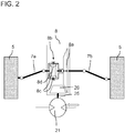
- FIG. 2 shows an example of how the hydraulic motor 21 can be operatively connected to the axle differential 8 of the front axle 4.
- the hydraulic motor 21 is arranged fixed to the chassis.
- a drive shaft 25 driven by the hydraulic motor 21 has at its distal end a drive bevel gear 26 which meshes with the ring gear 8a of the axle differential 8 of the front axle 4.
- the hydraulic motor 21 is integrated in a hydrostatic circuit 20 known per se, for example analogously to that in FIG Figure 1 Example shown, wherein a hydraulic pump 22 is mechanically driven via the mechanical drive train of the vehicle containing the internal combustion engine 9 and is hydraulically connected to the hydraulic motor 21 via fluid lines.
- the ring gear 8a is non-rotatably connected to the cage 8b of the axle differential 8 in a manner known per se.
- the axle differential is designed as a bevel gear differential gear, a pair of axle bevel gears 8d and a pair of differential bevel gears 8c being in engagement with one another.
- the axle bevel gears 8d drive the wheel drive shafts 7a and 7b via the driven shafts 8e of the axle differential 8 and thus transmit the drive power of the hydraulic motor 21 to the front wheels 5.
- the hydraulic motor 21 is thus not arranged coaxially to the axis of rotation R of the outputs 8e of the axle differential 8, but is arranged spatially offset from the axis of rotation R.
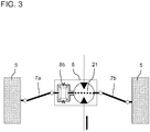
- FIG 3 shows an alternative embodiment.
- the hydraulic motor 21 is not axially offset to the axle differential 8 or to the axis of rotation R of the drives 8e of the axle differential 8 here. Rather, the hydraulic motor 21 is arranged coaxially with the axis of rotation R and drives the cage 8b of the axle differential 8 directly and thus replaces the ring gear 8a.
- the hydraulic motor 21 is designed as a radial piston motor, having an outer, fixed cam ring and an inner, circumferential cylinder housing which is non-rotatably connected to the cage 8b and can thus set it in a rotational movement.
- In the cage 8b there is in turn an axle bolt carrying differential gears, these differential gears 8c meshing with axle shaft gears 8d arranged on the wheel drive shafts 7a, 7b, which are each designed as bevel gears.
- the hydraulic motor 21 can optionally transmit its drive power to the wheels 5 of the second axle 4 with or without a transmission gear which has a defined reduction or transmission ratio.
Landscapes
- Engineering & Computer Science (AREA)
- Chemical & Material Sciences (AREA)
- Combustion & Propulsion (AREA)
- Transportation (AREA)
- Mechanical Engineering (AREA)
- Motor Power Transmission Devices (AREA)
- Arrangement And Driving Of Transmission Devices (AREA)
- Retarders (AREA)
Applications Claiming Priority (1)
| Application Number | Priority Date | Filing Date | Title |
|---|---|---|---|
| DE102018124014.7A DE102018124014A1 (de) | 2018-09-28 | 2018-09-28 | Kraftfahrzeug mit einem Hilfsantrieb für eine lenkbare Achse |
Publications (2)
| Publication Number | Publication Date |
|---|---|
| EP3628525A1 true EP3628525A1 (fr) | 2020-04-01 |
| EP3628525B1 EP3628525B1 (fr) | 2022-02-23 |
Family
ID=68069580
Family Applications (1)
| Application Number | Title | Priority Date | Filing Date |
|---|---|---|---|
| EP19199616.4A Active EP3628525B1 (fr) | 2018-09-28 | 2019-09-25 | Véhicule automobile doté d'un entraînement auxiliaire pour un essieu dirigeable |
Country Status (2)
| Country | Link |
|---|---|
| EP (1) | EP3628525B1 (fr) |
| DE (1) | DE102018124014A1 (fr) |
Cited By (1)
| Publication number | Priority date | Publication date | Assignee | Title |
|---|---|---|---|---|
| FR3123832A1 (fr) * | 2021-06-11 | 2022-12-16 | Psa Automobiles Sa | Véhicule à circuit de transmission hydraulique contrôlé pour la répartition de couple entre trains |
Citations (5)
| Publication number | Priority date | Publication date | Assignee | Title |
|---|---|---|---|---|
| EP1318064A2 (fr) * | 2001-12-04 | 2003-06-11 | DaimlerChrysler AG | Châssis modulaire pour un camion |
| EP1886861A2 (fr) | 2006-08-11 | 2008-02-13 | MAN Nutzfahrzeuge Österreich AG | Différentiell pour MAN-Hydrodrive |
| DE102011118111A1 (de) * | 2011-11-09 | 2012-05-24 | Daimler Ag | Antriebsstrang für einen Kraftwagen |
| WO2017081164A1 (fr) * | 2015-11-10 | 2017-05-18 | Poclain Hydraulics Industrie | Procédé d'engagement de l'assistance hydraulique |
| US20180065479A1 (en) * | 2015-03-13 | 2018-03-08 | Poclain Hydraulics Industrie | Vehicle-mounted hydraulic assistance device and method for evacuating such a device |
Family Cites Families (1)
| Publication number | Priority date | Publication date | Assignee | Title |
|---|---|---|---|---|
| JP3430754B2 (ja) * | 1995-11-29 | 2003-07-28 | 日産自動車株式会社 | 四輪駆動車 |
-
2018
- 2018-09-28 DE DE102018124014.7A patent/DE102018124014A1/de not_active Withdrawn
-
2019
- 2019-09-25 EP EP19199616.4A patent/EP3628525B1/fr active Active
Patent Citations (5)
| Publication number | Priority date | Publication date | Assignee | Title |
|---|---|---|---|---|
| EP1318064A2 (fr) * | 2001-12-04 | 2003-06-11 | DaimlerChrysler AG | Châssis modulaire pour un camion |
| EP1886861A2 (fr) | 2006-08-11 | 2008-02-13 | MAN Nutzfahrzeuge Österreich AG | Différentiell pour MAN-Hydrodrive |
| DE102011118111A1 (de) * | 2011-11-09 | 2012-05-24 | Daimler Ag | Antriebsstrang für einen Kraftwagen |
| US20180065479A1 (en) * | 2015-03-13 | 2018-03-08 | Poclain Hydraulics Industrie | Vehicle-mounted hydraulic assistance device and method for evacuating such a device |
| WO2017081164A1 (fr) * | 2015-11-10 | 2017-05-18 | Poclain Hydraulics Industrie | Procédé d'engagement de l'assistance hydraulique |
Non-Patent Citations (1)
| Title |
|---|
| REUTER M ET AL: "DIE BREMSANLAGE DER NEUEN TRANSPORTER-GENERATION SPRINTER VON MERCEDES-BENZ", ATZ, SPRINGER VIEWEG, DE, vol. 98, no. 1, 1 January 1996 (1996-01-01), pages - 35, XP000548181, ISSN: 0001-2785 * |
Cited By (1)
| Publication number | Priority date | Publication date | Assignee | Title |
|---|---|---|---|---|
| FR3123832A1 (fr) * | 2021-06-11 | 2022-12-16 | Psa Automobiles Sa | Véhicule à circuit de transmission hydraulique contrôlé pour la répartition de couple entre trains |
Also Published As
| Publication number | Publication date |
|---|---|
| EP3628525B1 (fr) | 2022-02-23 |
| DE102018124014A1 (de) | 2020-04-02 |
Similar Documents
| Publication | Publication Date | Title |
|---|---|---|
| EP3165395B1 (fr) | Véhicule utilitaire, en particulier poids lourd, comprenant au moins un groupe d'essieu jumelé | |
| EP0414722B1 (fr) | Tracteur toutes roues motrices | |
| DE10310713B4 (de) | Achsdifferential mit elektronischem Achswellenmanagement | |
| DE102009049856B4 (de) | Getriebeanordnung für ein Fahrzeug und Getriebe mit der Getriebeanordnung | |
| EP3888981B1 (fr) | Entraînement d'essieu | |
| AT503359A2 (de) | Getriebemodul zur variablen drehmomentverteilung | |
| DE69518507T2 (de) | Fahrantriebsvorrichtung für arbeitsfahrzeug | |
| DE102006038358B4 (de) | Achsantriebseinheit für einen Antriebsstrang | |
| EP1733156A2 (fr) | Boite de transfert | |
| EP0528319A1 (fr) | Transmission pour véhicules avec différentiel central | |
| DE4323539C1 (de) | Radlagereinheit eines Kraftfahrzeugs | |
| DE102013203567A1 (de) | Doppelrad-Antriebsmodul | |
| EP0201493B1 (fr) | Vehicule a essieux multiples avec entrainement independant des roues | |
| DE102021208545A1 (de) | Getriebe für ein Fahrzeug sowie Antriebsstrang mit einem solchen Getriebe | |
| DE2335629B2 (de) | Hydrostatisch-mechanischer antrieb fuer land- und bauwirtschaftlich genutzte fahrzeuge | |
| DE102021213063B4 (de) | Lenkantrieb für eine Lenkachse eines lenkbaren Fahrzeugs, Lenkachse und Flurförderzeug | |
| EP3628525B1 (fr) | Véhicule automobile doté d'un entraînement auxiliaire pour un essieu dirigeable | |
| DE102018205126B4 (de) | Torque Vectoring-Überlagerungseinheit für ein Differenzialausgleichsgetriebe | |
| WO2012146352A1 (fr) | Dispositif d'entraînement pour un véhicule automobile à traction avant, arrière ou intégrale | |
| EP2559581A2 (fr) | Système d'entraînement pour un véhicule automobile équipé d'un système de freinage agissant comme un différentiel à blocage | |
| DE3913487A1 (de) | Allradgetriebener ackerschlepper | |
| DE3411746C1 (de) | Allradantrieb fuer Kraftfahrzeuge | |
| DE102021208543A1 (de) | Getriebe für ein Fahrzeug sowie Antriebsstrang mit einem solchen Getriebe | |
| DE102016220477B4 (de) | Achsantriebssystem sowie Verfahren zur Steuerung eines Achsantriebssystems | |
| DE102024129912A1 (de) | Geländefahrzeug |
Legal Events
| Date | Code | Title | Description |
|---|---|---|---|
| PUAI | Public reference made under article 153(3) epc to a published international application that has entered the european phase |
Free format text: ORIGINAL CODE: 0009012 |
|
| STAA | Information on the status of an ep patent application or granted ep patent |
Free format text: STATUS: THE APPLICATION HAS BEEN PUBLISHED |
|
| AK | Designated contracting states |
Kind code of ref document: A1 Designated state(s): AL AT BE BG CH CY CZ DE DK EE ES FI FR GB GR HR HU IE IS IT LI LT LU LV MC MK MT NL NO PL PT RO RS SE SI SK SM TR |
|
| AX | Request for extension of the european patent |
Extension state: BA ME |
|
| STAA | Information on the status of an ep patent application or granted ep patent |
Free format text: STATUS: REQUEST FOR EXAMINATION WAS MADE |
|
| 17P | Request for examination filed |
Effective date: 20200923 |
|
| RBV | Designated contracting states (corrected) |
Designated state(s): AL AT BE BG CH CY CZ DE DK EE ES FI FR GB GR HR HU IE IS IT LI LT LU LV MC MK MT NL NO PL PT RO RS SE SI SK SM TR |
|
| STAA | Information on the status of an ep patent application or granted ep patent |
Free format text: STATUS: EXAMINATION IS IN PROGRESS |
|
| 17Q | First examination report despatched |
Effective date: 20210212 |
|
| GRAP | Despatch of communication of intention to grant a patent |
Free format text: ORIGINAL CODE: EPIDOSNIGR1 |
|
| STAA | Information on the status of an ep patent application or granted ep patent |
Free format text: STATUS: GRANT OF PATENT IS INTENDED |
|
| INTG | Intention to grant announced |
Effective date: 20211202 |
|
| GRAS | Grant fee paid |
Free format text: ORIGINAL CODE: EPIDOSNIGR3 |
|
| GRAA | (expected) grant |
Free format text: ORIGINAL CODE: 0009210 |
|
| STAA | Information on the status of an ep patent application or granted ep patent |
Free format text: STATUS: THE PATENT HAS BEEN GRANTED |
|
| AK | Designated contracting states |
Kind code of ref document: B1 Designated state(s): AL AT BE BG CH CY CZ DE DK EE ES FI FR GB GR HR HU IE IS IT LI LT LU LV MC MK MT NL NO PL PT RO RS SE SI SK SM TR |
|
| REG | Reference to a national code |
Ref country code: GB Ref legal event code: FG4D Free format text: NOT ENGLISH |
|
| REG | Reference to a national code |
Ref country code: CH Ref legal event code: EP |
|
| REG | Reference to a national code |
Ref country code: AT Ref legal event code: REF Ref document number: 1470201 Country of ref document: AT Kind code of ref document: T Effective date: 20220315 |
|
| REG | Reference to a national code |
Ref country code: IE Ref legal event code: FG4D Free format text: LANGUAGE OF EP DOCUMENT: GERMAN |
|
| REG | Reference to a national code |
Ref country code: DE Ref legal event code: R096 Ref document number: 502019003473 Country of ref document: DE |
|
| REG | Reference to a national code |
Ref country code: SE Ref legal event code: TRGR |
|
| REG | Reference to a national code |
Ref country code: NL Ref legal event code: FP |
|
| REG | Reference to a national code |
Ref country code: LT Ref legal event code: MG9D |
|
| PG25 | Lapsed in a contracting state [announced via postgrant information from national office to epo] |
Ref country code: RS Free format text: LAPSE BECAUSE OF FAILURE TO SUBMIT A TRANSLATION OF THE DESCRIPTION OR TO PAY THE FEE WITHIN THE PRESCRIBED TIME-LIMIT Effective date: 20220223 Ref country code: PT Free format text: LAPSE BECAUSE OF FAILURE TO SUBMIT A TRANSLATION OF THE DESCRIPTION OR TO PAY THE FEE WITHIN THE PRESCRIBED TIME-LIMIT Effective date: 20220623 Ref country code: NO Free format text: LAPSE BECAUSE OF FAILURE TO SUBMIT A TRANSLATION OF THE DESCRIPTION OR TO PAY THE FEE WITHIN THE PRESCRIBED TIME-LIMIT Effective date: 20220523 Ref country code: LT Free format text: LAPSE BECAUSE OF FAILURE TO SUBMIT A TRANSLATION OF THE DESCRIPTION OR TO PAY THE FEE WITHIN THE PRESCRIBED TIME-LIMIT Effective date: 20220223 Ref country code: HR Free format text: LAPSE BECAUSE OF FAILURE TO SUBMIT A TRANSLATION OF THE DESCRIPTION OR TO PAY THE FEE WITHIN THE PRESCRIBED TIME-LIMIT Effective date: 20220223 Ref country code: ES Free format text: LAPSE BECAUSE OF FAILURE TO SUBMIT A TRANSLATION OF THE DESCRIPTION OR TO PAY THE FEE WITHIN THE PRESCRIBED TIME-LIMIT Effective date: 20220223 Ref country code: BG Free format text: LAPSE BECAUSE OF FAILURE TO SUBMIT A TRANSLATION OF THE DESCRIPTION OR TO PAY THE FEE WITHIN THE PRESCRIBED TIME-LIMIT Effective date: 20220523 |
|
| PG25 | Lapsed in a contracting state [announced via postgrant information from national office to epo] |
Ref country code: PL Free format text: LAPSE BECAUSE OF FAILURE TO SUBMIT A TRANSLATION OF THE DESCRIPTION OR TO PAY THE FEE WITHIN THE PRESCRIBED TIME-LIMIT Effective date: 20220223 Ref country code: LV Free format text: LAPSE BECAUSE OF FAILURE TO SUBMIT A TRANSLATION OF THE DESCRIPTION OR TO PAY THE FEE WITHIN THE PRESCRIBED TIME-LIMIT Effective date: 20220223 Ref country code: GR Free format text: LAPSE BECAUSE OF FAILURE TO SUBMIT A TRANSLATION OF THE DESCRIPTION OR TO PAY THE FEE WITHIN THE PRESCRIBED TIME-LIMIT Effective date: 20220524 Ref country code: FI Free format text: LAPSE BECAUSE OF FAILURE TO SUBMIT A TRANSLATION OF THE DESCRIPTION OR TO PAY THE FEE WITHIN THE PRESCRIBED TIME-LIMIT Effective date: 20220223 |
|
| PG25 | Lapsed in a contracting state [announced via postgrant information from national office to epo] |
Ref country code: IS Free format text: LAPSE BECAUSE OF FAILURE TO SUBMIT A TRANSLATION OF THE DESCRIPTION OR TO PAY THE FEE WITHIN THE PRESCRIBED TIME-LIMIT Effective date: 20220623 |
|
| PG25 | Lapsed in a contracting state [announced via postgrant information from national office to epo] |
Ref country code: SM Free format text: LAPSE BECAUSE OF FAILURE TO SUBMIT A TRANSLATION OF THE DESCRIPTION OR TO PAY THE FEE WITHIN THE PRESCRIBED TIME-LIMIT Effective date: 20220223 Ref country code: SK Free format text: LAPSE BECAUSE OF FAILURE TO SUBMIT A TRANSLATION OF THE DESCRIPTION OR TO PAY THE FEE WITHIN THE PRESCRIBED TIME-LIMIT Effective date: 20220223 Ref country code: RO Free format text: LAPSE BECAUSE OF FAILURE TO SUBMIT A TRANSLATION OF THE DESCRIPTION OR TO PAY THE FEE WITHIN THE PRESCRIBED TIME-LIMIT Effective date: 20220223 Ref country code: EE Free format text: LAPSE BECAUSE OF FAILURE TO SUBMIT A TRANSLATION OF THE DESCRIPTION OR TO PAY THE FEE WITHIN THE PRESCRIBED TIME-LIMIT Effective date: 20220223 Ref country code: DK Free format text: LAPSE BECAUSE OF FAILURE TO SUBMIT A TRANSLATION OF THE DESCRIPTION OR TO PAY THE FEE WITHIN THE PRESCRIBED TIME-LIMIT Effective date: 20220223 Ref country code: CZ Free format text: LAPSE BECAUSE OF FAILURE TO SUBMIT A TRANSLATION OF THE DESCRIPTION OR TO PAY THE FEE WITHIN THE PRESCRIBED TIME-LIMIT Effective date: 20220223 |
|
| REG | Reference to a national code |
Ref country code: DE Ref legal event code: R097 Ref document number: 502019003473 Country of ref document: DE |
|
| PG25 | Lapsed in a contracting state [announced via postgrant information from national office to epo] |
Ref country code: AL Free format text: LAPSE BECAUSE OF FAILURE TO SUBMIT A TRANSLATION OF THE DESCRIPTION OR TO PAY THE FEE WITHIN THE PRESCRIBED TIME-LIMIT Effective date: 20220223 |
|
| PLBE | No opposition filed within time limit |
Free format text: ORIGINAL CODE: 0009261 |
|
| STAA | Information on the status of an ep patent application or granted ep patent |
Free format text: STATUS: NO OPPOSITION FILED WITHIN TIME LIMIT |
|
| 26N | No opposition filed |
Effective date: 20221124 |
|
| PG25 | Lapsed in a contracting state [announced via postgrant information from national office to epo] |
Ref country code: SI Free format text: LAPSE BECAUSE OF FAILURE TO SUBMIT A TRANSLATION OF THE DESCRIPTION OR TO PAY THE FEE WITHIN THE PRESCRIBED TIME-LIMIT Effective date: 20220223 |
|
| PG25 | Lapsed in a contracting state [announced via postgrant information from national office to epo] |
Ref country code: MC Free format text: LAPSE BECAUSE OF FAILURE TO SUBMIT A TRANSLATION OF THE DESCRIPTION OR TO PAY THE FEE WITHIN THE PRESCRIBED TIME-LIMIT Effective date: 20220223 |
|
| REG | Reference to a national code |
Ref country code: CH Ref legal event code: PL |
|
| REG | Reference to a national code |
Ref country code: BE Ref legal event code: MM Effective date: 20220930 |
|
| PG25 | Lapsed in a contracting state [announced via postgrant information from national office to epo] |
Ref country code: LU Free format text: LAPSE BECAUSE OF NON-PAYMENT OF DUE FEES Effective date: 20220925 |
|
| PG25 | Lapsed in a contracting state [announced via postgrant information from national office to epo] |
Ref country code: LI Free format text: LAPSE BECAUSE OF NON-PAYMENT OF DUE FEES Effective date: 20220930 Ref country code: IE Free format text: LAPSE BECAUSE OF NON-PAYMENT OF DUE FEES Effective date: 20220925 Ref country code: CH Free format text: LAPSE BECAUSE OF NON-PAYMENT OF DUE FEES Effective date: 20220930 |
|
| PG25 | Lapsed in a contracting state [announced via postgrant information from national office to epo] |
Ref country code: BE Free format text: LAPSE BECAUSE OF NON-PAYMENT OF DUE FEES Effective date: 20220930 |
|
| PG25 | Lapsed in a contracting state [announced via postgrant information from national office to epo] |
Ref country code: HU Free format text: LAPSE BECAUSE OF FAILURE TO SUBMIT A TRANSLATION OF THE DESCRIPTION OR TO PAY THE FEE WITHIN THE PRESCRIBED TIME-LIMIT; INVALID AB INITIO Effective date: 20190925 |
|
| PG25 | Lapsed in a contracting state [announced via postgrant information from national office to epo] |
Ref country code: CY Free format text: LAPSE BECAUSE OF FAILURE TO SUBMIT A TRANSLATION OF THE DESCRIPTION OR TO PAY THE FEE WITHIN THE PRESCRIBED TIME-LIMIT Effective date: 20220223 |
|
| GBPC | Gb: european patent ceased through non-payment of renewal fee |
Effective date: 20230925 |
|
| PG25 | Lapsed in a contracting state [announced via postgrant information from national office to epo] |
Ref country code: MK Free format text: LAPSE BECAUSE OF FAILURE TO SUBMIT A TRANSLATION OF THE DESCRIPTION OR TO PAY THE FEE WITHIN THE PRESCRIBED TIME-LIMIT Effective date: 20220223 |
|
| PG25 | Lapsed in a contracting state [announced via postgrant information from national office to epo] |
Ref country code: GB Free format text: LAPSE BECAUSE OF NON-PAYMENT OF DUE FEES Effective date: 20230925 |
|
| PG25 | Lapsed in a contracting state [announced via postgrant information from national office to epo] |
Ref country code: GB Free format text: LAPSE BECAUSE OF NON-PAYMENT OF DUE FEES Effective date: 20230925 |
|
| PG25 | Lapsed in a contracting state [announced via postgrant information from national office to epo] |
Ref country code: MT Free format text: LAPSE BECAUSE OF FAILURE TO SUBMIT A TRANSLATION OF THE DESCRIPTION OR TO PAY THE FEE WITHIN THE PRESCRIBED TIME-LIMIT Effective date: 20220223 |
|
| PGFP | Annual fee paid to national office [announced via postgrant information from national office to epo] |
Ref country code: DE Payment date: 20250926 Year of fee payment: 7 |
|
| PGFP | Annual fee paid to national office [announced via postgrant information from national office to epo] |
Ref country code: NL Payment date: 20250925 Year of fee payment: 7 Ref country code: IT Payment date: 20250922 Year of fee payment: 7 |
|
| PGFP | Annual fee paid to national office [announced via postgrant information from national office to epo] |
Ref country code: FR Payment date: 20250925 Year of fee payment: 7 |
|
| PGFP | Annual fee paid to national office [announced via postgrant information from national office to epo] |
Ref country code: SE Payment date: 20250924 Year of fee payment: 7 |
|
| REG | Reference to a national code |
Ref country code: AT Ref legal event code: MM01 Ref document number: 1470201 Country of ref document: AT Kind code of ref document: T Effective date: 20240925 |
|
| PG25 | Lapsed in a contracting state [announced via postgrant information from national office to epo] |
Ref country code: TR Free format text: LAPSE BECAUSE OF FAILURE TO SUBMIT A TRANSLATION OF THE DESCRIPTION OR TO PAY THE FEE WITHIN THE PRESCRIBED TIME-LIMIT Effective date: 20220223 |
|
| PG25 | Lapsed in a contracting state [announced via postgrant information from national office to epo] |
Ref country code: AT Free format text: LAPSE BECAUSE OF NON-PAYMENT OF DUE FEES Effective date: 20240925 |
|
| PGFP | Annual fee paid to national office [announced via postgrant information from national office to epo] |
Ref country code: AT Payment date: 20260410 Year of fee payment: 5 |