EP3629366A2 - Vacuum system and vacuum pump - Google Patents
Vacuum system and vacuum pump Download PDFInfo
- Publication number
- EP3629366A2 EP3629366A2 EP20152401.4A EP20152401A EP3629366A2 EP 3629366 A2 EP3629366 A2 EP 3629366A2 EP 20152401 A EP20152401 A EP 20152401A EP 3629366 A2 EP3629366 A2 EP 3629366A2
- Authority
- EP
- European Patent Office
- Prior art keywords
- pump
- partial
- jet
- rotor
- vacuum
- Prior art date
- Legal status (The legal status is an assumption and is not a legal conclusion. Google has not performed a legal analysis and makes no representation as to the accuracy of the status listed.)
- Granted
Links
Images


Classifications
-
- F—MECHANICAL ENGINEERING; LIGHTING; HEATING; WEAPONS; BLASTING
- F04—POSITIVE - DISPLACEMENT MACHINES FOR LIQUIDS; PUMPS FOR LIQUIDS OR ELASTIC FLUIDS
- F04B—POSITIVE-DISPLACEMENT MACHINES FOR LIQUIDS; PUMPS
- F04B37/00—Pumps having pertinent characteristics not provided for in, or of interest apart from, groups F04B25/00 - F04B35/00
- F04B37/06—Pumps having pertinent characteristics not provided for in, or of interest apart from, groups F04B25/00 - F04B35/00 for evacuating by thermal means
- F04B37/08—Pumps having pertinent characteristics not provided for in, or of interest apart from, groups F04B25/00 - F04B35/00 for evacuating by thermal means by condensing or freezing, e.g. cryogenic pumps
-
- F—MECHANICAL ENGINEERING; LIGHTING; HEATING; WEAPONS; BLASTING
- F04—POSITIVE - DISPLACEMENT MACHINES FOR LIQUIDS; PUMPS FOR LIQUIDS OR ELASTIC FLUIDS
- F04B—POSITIVE-DISPLACEMENT MACHINES FOR LIQUIDS; PUMPS
- F04B37/00—Pumps having pertinent characteristics not provided for in, or of interest apart from, groups F04B25/00 - F04B35/00
- F04B37/10—Pumps having pertinent characteristics not provided for in, or of interest apart from, groups F04B25/00 - F04B35/00 for special use
- F04B37/14—Pumps having pertinent characteristics not provided for in, or of interest apart from, groups F04B25/00 - F04B35/00 for special use to obtain high vacuum
-
- F—MECHANICAL ENGINEERING; LIGHTING; HEATING; WEAPONS; BLASTING
- F04—POSITIVE - DISPLACEMENT MACHINES FOR LIQUIDS; PUMPS FOR LIQUIDS OR ELASTIC FLUIDS
- F04D—NON-POSITIVE-DISPLACEMENT PUMPS
- F04D19/00—Axial-flow pumps
- F04D19/02—Multi-stage pumps
- F04D19/04—Multi-stage pumps specially adapted to the production of a high vacuum, e.g. molecular pumps
- F04D19/042—Turbomolecular vacuum pumps
-
- F—MECHANICAL ENGINEERING; LIGHTING; HEATING; WEAPONS; BLASTING
- F04—POSITIVE - DISPLACEMENT MACHINES FOR LIQUIDS; PUMPS FOR LIQUIDS OR ELASTIC FLUIDS
- F04D—NON-POSITIVE-DISPLACEMENT PUMPS
- F04D19/00—Axial-flow pumps
- F04D19/02—Multi-stage pumps
- F04D19/04—Multi-stage pumps specially adapted to the production of a high vacuum, e.g. molecular pumps
- F04D19/046—Combinations of two or more different types of pumps
-
- H—ELECTRICITY
- H01—ELECTRIC ELEMENTS
- H01J—ELECTRIC DISCHARGE TUBES OR DISCHARGE LAMPS
- H01J49/00—Particle spectrometers or separator tubes
- H01J49/02—Details
- H01J49/24—Vacuum systems, e.g. maintaining desired pressures
Definitions
- the present invention relates to a vacuum system, in particular a gas analysis system and / or mass spectrometry system, comprising a vacuum pump with a pump-active area in which a gas can be conveyed by means of an active pump element, and a device for generating a beam of particles.
- Particle beams are often generated and used in vacuum systems, for example in mass spectrometry systems.
- deflection devices are frequently used, by means of which the beam can be deflected in such a way that different components of the beam are deflected differently, so that at least a first and a second partial beam can be formed.
- these have the purpose of dividing the particle beam so that only certain components to be analyzed, which in particular form the first partial beam, are guided in a desired direction, in particular to an analyzer unit.
- the remaining components, which in particular form the second partial beam have a different direction after the passage of the deflection device than the components to be analyzed.
- the deflection device thus acts as a filter.
- such a deflection often by approximately 90 °, enables a compact design of the mass spectrometry system.
- the jet directed into the pump-active area can e.g. act as a partial beam after passage through a filter and / or separation device.
- the beam has a particle stream with a specific direction and that this direction is advantageously used in order to capture the particles directly.
- it can also be a type of main beam and / or an overall beam, for example.
- the invention is directed to increasing the probability of capturing a particular particle of the beam. This is achieved in a structurally particularly simple manner by the invention.
- the vacuum system can preferably comprise a deflection device, by means of which the beam can be deflected such that different components of the beam are deflected differently, so that at least a first and a second partial beam can be formed, the second partial beam being guided into the pump-active area.
- the jet is therefore at least partially guided into the pump-active area.
- a, in particular second, partial jet can also be meant.
- the invention thus enables in particular good separation of the partial beams and high quality of the first partial beam, which can, for example, have a positive effect on an analysis of the first partial beam.
- the gas components of the second partial beam are often those components that are undesirable with regard to an analysis task, that is to say represent undesired molecules. These can be called dirt particles.
- second partial jets or dirt particles typically land on static components in the region of or adjacent to the deflection device.
- a diaphragm is also often arranged downstream of the deflection device, through which the first partial jet can pass, but on the surface of which the dirt particles impinge apart from the first partial jet or a passage for this. All dirt particles that land on static surfaces desorb after a certain time from the surface in question with a statistical distribution of the direction. On the one hand, this means an increased probability that dirt particles will reach the analyzer unit despite all filter devices.
- the dirt particles can collide with the gas molecules of the first partial jet to be analyzed, thus reducing its quality. This is because the molecules of the first partial beam are thereby deflected and the number of molecules to be analyzed that reach the analyzer unit is reduced.
- the invention now enables dirt particles to be removed directly by the pumping action of the vacuum pump.
- the direction or kinetic energy of the dirt particles in the particle beam is advantageously used in order to actively supply them to the pump-active area of the vacuum pump.
- the pump-active area then actively gives the dirt particles or the second partial jet a preferred direction in the pumping direction, so that the dirt particles are actively guided away from the first partial jet and in particular from an analyzer unit.
- effective evacuation of vacuum chambers in a gas analysis system is often difficult, namely due to disadvantageous geometries and conductance values.
- better evacuation enables better analytical accuracy.
- the invention enables the use of the beam direction or the kinetic energy of the particles and better evacuation and thus, in particular, improved analysis accuracy due to active evacuation.
- a pump-active area is generally to be understood as an active area of an active pump element of the vacuum pump, for example a rotor or rotor element, in particular a turbo-rotor disk.
- the jet in particular the second partial jet, is guided in particular into an active rotor area.
- this is, in particular, an area swept by the rotor blades during operation.
- a rotor core which itself has no pump-active effect but only has a structural function, does not belong to the pump-active area.
- the beam is generally not advantageously guided onto a rotor core or the beam is guided past a rotor core.
- the deflection device deflects different components of the particle beam differently. Certain components are typically not distracted at all, namely in particular uncharged components.
- the general rule is that at least one of the first and second partial beams has to be deflected by the deflection device in order to divide the partial beams into those.
- the second partial beam cannot be deflected by the deflection device or can be aligned in front of the deflection device in continuation of the particle beam.
- Uncharged particles particularly frequently form undesired molecules or dirt particles with regard to the analysis task. If the partial jet of uncharged components is directed into the pump-active area, a particularly large proportion of dirt particles is thus removed directly.
- the molecules of the jet which is guided into the pump-active area, are in particular captured directly by at least one pump-active element of the vacuum pump in the pump-active area.
- a pump-active element designed as a turbo rotor that the molecules of the jet pass through the area swept by the rotor blades and are subsequently "held” downstream by the generally known operating principle of the turbo rotor, that is, from a physical point of view, the probability that a respective one is reduced Molecule gets back into the area upstream of the rotor blades.
- different partial beams After passing through a deflection device, different partial beams generally comprise different components and have different directions.
- a partial beam does not necessarily have only one component or one type of particle.
- the second partial jet can, for example, have a large number of constituents, all of which can form dirt particles. This applies in particular to a second partial beam, which is directed straight ahead with respect to the common beam before passing the deflection device and / or has uncharged molecules.
- the first partial beam can also have fundamentally different components, the differences typically being small.
- the deflection device typically does not split the common particle beam into only two absolutely discrete partial beams. Rather, particle beams in such systems typically have a large number of constituents, usually only a small part of the constituents being to be analyzed, frequently a specific type of ion and / or molecule. Consequently, after the deflection device has passed, a plurality of, in particular second, partial beams typically form a fan-like pattern.
- at least one second partial jet can in particular be guided into the pump-active area, but several second partial jets or partial jets with dirt particles are advantageously guided into the pump-active area in order to directly remove as many dirt particles as possible.
- How many second partial beams can be guided into the active pumping area and which angular area of the fan from Partial jets can be guided into the active pumping area is particularly dependent on the geometric conditions in the vacuum pump. In principle, therefore, more than two partial beams can also be formed, for example a plurality of first partial beams that are not led into the pump-active region and / or several second partial beams that are led into the pump-active region.
- the second partial jet can in particular have or consist essentially of uncharged particles and / or particles of a carrier gas.
- a carrier gas often makes up a large part of the pressure in a vacuum system, in particular mass spectrometry system. Accordingly, the invention advantageously allows a large proportion of particles which are not intended to be part of the first partial jet to be pumped off directly.
- a carrier gas is, for example, an inert gas and / or air. E.g. can be used as a carrier gas helium.
- the second partial jet comprises, for example, oxygen and / or nitrogen, in particular uncharged particles thereof.
- the second partial beam mainly comprises one type of molecule and / or has a particle flow that is many times higher than the first particle beam.
- a type of molecule to be analyzed in a gas analysis system, in particular mass spectrometer only makes up a small part of the gas stream and / or a carrier gas makes up a vast majority.
- gas components are deflected differently and that as large a part as possible of gas components which are undesirable, in particular with regard to an analysis task, is led directly into the pump-active area using their direction.
- these, in particular undesirable, components can be actively removed, namely in particular out of the area of the first partial beam and, for example, away from an analysis area or an area of an analyzer unit.
- the deflection device divides the particle beam into partial beams.
- the beam before passing the deflection device is also referred to here as a common (particle) beam, in delimitation to the partial beams which form during and / or after passage of the deflection device.
- the vacuum system can, for example, also have a plurality of deflection devices, for example, each with an advantageous guidance of a partial jet into a pump-active area of a vacuum pump.
- a deflection device for example, a wide variety of other filter elements can also be used, such as an aperture and / or a quadrupole.
- the beam is guided into the pump-active region with at least one directional component in the pumping direction. This supports the pumping action of the pumping area and the molecules of the jet are discharged particularly effectively.
- the first partial jet is not guided into the pump-active area.
- the first partial jet can be guided to an area outside the vacuum pump.
- the first partial beam can be guided to an analyzer unit, for example directly or through at least one further filter element, in particular an aperture.
- the first partial jet can pass a housing of the vacuum pump or be guided through one.
- the vacuum pump can comprise a rotor which can be driven to rotate about a rotor axis.
- An active pump element of the vacuum pump or the pump-active area can be coupled to the rotor, so that the rotor drives the pump element.
- the beam can in particular be guided into an active rotor area of the rotor or of the active pump element.
- a pumping direction and / or a rotor axis of an active pump element and / or the vacuum pump is oriented obliquely with respect to a direction of the jet, in particular before passage of one or the deflection device.
- the jet and in particular a second partial jet directed straight ahead with respect to a common jet can be guided into the pump-active region particularly advantageously with regard to the pumping action.
- such an arrangement is particularly advantageous with regard to the installation space.
- an angle between a pumping direction and / or a rotor axis of the active pump element and / or the vacuum pump and a direction of the jet, in particular before passage through one or the deflection device can be in the range from 40 ° to 60 °, preferably in the range of 50 ° up to 55 °.
- These values are influenced by the particle speed, the rotor blade revolution speed in the "target area" of the beam and the rotor blade angle or angle of attack there.
- the angle can be optimized three-dimensionally depending on the case.
- a pumping direction and / or a rotor axis of the active pump element and / or the vacuum pump can preferably be oriented obliquely with respect to a direction of the first and / or the second partial jet after passage of the deflection device. This is also conducive to a compact design.
- the vacuum pump can be designed in one or more stages, for example.
- Multi-stage means that the vacuum pump has at least two pump stages. At least two pump stages can preferably be connected in series. The pump stages can be driven by a common rotor, for example.
- the vacuum pump has at least two pump stages, preferably connected in series, an intermediate stage region being arranged between the pump stages, in particular in the pumping direction.
- the pump stages can in particular be spaced apart via this intermediate stage region.
- the beam is preferably passed through the intermediate stage area.
- the jet in particular a second partial jet, can be guided into a pump stage, which is arranged downstream of the intermediate stage region, in particular in the pumping direction. This enables on the one hand a particularly compact design and on the other hand a particularly good removal of the particles, in particular dirt particles.
- a pump stage is defined in particular by an active pump element, in particular in cooperation with a static and / or passive element.
- a turbo rotor can in principle be designed, for example, with a plurality of rows of blades connected in one piece and / or can have one or more turbo rotor disks.
- the beam can generally be directed preferably into the active region of the active pump element and / or onto a rotating element, for example a turbo rotor disk.
- the first partial beam can preferably be led out of the vacuum pump after passage of the intermediate stage area and / or a deflection device, for example to an analyzer unit.
- an analyzer unit can be designed, for example, as a detector.
- the vacuum pump has a first intermediate connection at the intermediate stage area for the entry of the jet into the intermediate stage area and / or a second intermediate connection for exit of the first partial jet from the intermediate stage area.
- the first and / or the second intermediate connection can have, for example, a flange, in particular its own.
- the intermediate connections can preferably be arranged at least essentially opposite one another, in particular with respect to a rotor axis and / or pump direction.
- The, in particular common, beam and / or the first partial beam can thus advantageously enter or exit the intermediate stage area.
- the intermediate connections are not necessarily exactly radially opposite, i.e. H. offset by 180 ° around the rotor axis.
- an eccentric connecting axis of the intermediate connections which in particular leads past a rotor core, is preferred. This enables a particularly advantageous gas flow.
- radially opposite intermediate connections are possible in principle, in particular in connection with a deflection device which at least partially deflects the gas jet around a rotor core.
- the intermediate connections can preferably be formed separately from one another and / or be spaced apart in the circumferential direction.
- a housing wall preferably extends in the circumferential direction between the intermediate connections, in particular over at least 20 °, preferably at least 35 °. The quality of the first partial beam is further improved by the separation of the intermediate connections.
- a deflection device can have a magnetic and / or electric field, for example.
- a magnetic field can be provided, for example, by a permanent magnet or, for example, also by an electromagnet will.
- a magnetic and / or electric field causes the different deflection of charged particles, in particular depending on their mass.
- the deflection device can have a field generating device, such as a magnet or an electrode.
- the deflection device can preferably be effective and / or arranged in or on the intermediate stage area.
- the term "effective" refers in particular to the electrical and / or magnetic field of the deflection device, that is to say generally to its effective range.
- the deflection device can also, for example, components such as have a field generating device outside its effective range. Consequently, the term “arranged” at least also refers to the effective range of the deflection device.
- an electrical and / or magnetic field of the deflection device can be arranged in and or at the intermediate stage area.
- a deflection device or an electrical and / or magnetic field can also be arranged, for example, radially outside the intermediate stage area, for example on or in the area of an intermediate connection, in particular of that intermediate connection for the entry of the common beam.
- the arrangement of a, in particular (electro) magnetic, deflection device in the region of at least one of the intermediate connections is likewise advantageously possible.
- An arrangement of passive and / or permanent magnetic as well as active deflection elements is possible on the one hand in the vacuum range or on the other hand also outside the vacuum range or in the atmosphere.
- a deflection device or a deflection element can be arranged in the area of the pump housing and / or on the outside of the pump housing.
- the deflection device itself can also be arranged outside the vacuum area in such a way that it is effective in the vacuum area so that in particular an electric and / or magnetic field extends into the vacuum area, in particular into the intermediate stage area.
- deflection devices can also be provided, also in or on the intermediate stage area.
- two deflection devices can be provided at, in or on the respective intermediate connections.
- the use of several deflection devices is particularly advantageous with regard to the installation space. Thus, it is not necessary to provide a large deflection device that completely fulfills the desired deflection, but rather the desired deflection can be divided into several deflection devices, which can subsequently be made smaller. This makes it easier to arrange them in terms of the overall installation space required.
- a magnetic and / or electrical field of a deflection device penetrates the rotating parts of a rotor as little as possible.
- several and / or small deflection devices which can preferably also be arranged outside the intermediate stage area, have proven to be advantageous. Eddy current losses in the rotor and an associated undesired heating in the rotor can thus be reduced.
- the jet can preferably be aligned eccentrically with respect to a rotor axis of the vacuum pump and / or can be guided past a rotor core, in particular one that is not pump-active. This applies in particular to the common jet, that is to say before it passes through the deflection device, and / or to the first and / or second partial jet.
- the jet in particular the second partial jet, is guided into the pump-active region in a direction that supports the pumping action.
- the jet can be guided into the pump-active area in such a way that the particles of the jet are captured particularly reliably.
- the jet in the case of a turbomolecular vacuum pump or turbopump stage, can preferably have a direction which, when entering the pump-active region, runs with at least one component against the direction of rotation of the turbo rotor. The jet thus runs against the rotor blades.
- the jet preferably also has a directional component in the pumping direction or parallel to the rotor axis in the direction of the outlet.
- an entry direction of the jet against the local direction of rotation of the rotor is particularly advantageous, so that the particles can at best pass through the first rotor disk without blade contact and only receive initial contact with subsequent deflection in the usual cosine distribution in the molecular pressure range at the stator disk below .
- the jet can be guided in such a way that its particles are captured by them without colliding with pump elements designed as rotor elements, such as, for example, turbo rotor blades.
- pump elements designed as rotor elements such as, for example, turbo rotor blades.
- the beam is aligned in particular taking into account its particle speed, the angle of attack of the rotor blades and / or the speed of rotation of the rotor or the rotor blades.
- the choice of the point of entry of the jet into the pump-active area in relation to the active rotor disk diameter or to the effective outer and inner diameters of the rotor blades is also subject to optimization, since the first deflection point on a stator disk behind it has a significant influence becomes.
- This deflection point should advantageously lie within an imaginary ring cylinder in the axial continuation of the area covered by the rotor blades, so that an optimal pumping can take place.
- the active pump element is formed by a turbo rotor disk with a plurality of rotor blades arranged distributed over the circumference of the turbo rotor disk, the rotor blades having a radial extension from a radially inner end to a radially outer end of the rotor blades.
- the jet can preferably be directed onto a radial region of the rotor blades which is spaced from the radially inner end and / or from the radially outer end of the rotor blades by at least a quarter of the radial extent.
- the jet can be guided onto the rotor blades from the radially outer end measured approximately radially in the center or approximately at a third of the radial extent.
- the pump-active element is a rotor element, the beam being guided into the pump-active region of the rotor element such that the beam has a direction, in particular, at an entry point of the beam into the pump-active region with respect to a cross section perpendicular to the rotor axis, which is directed outwards, tangentially or inwards.
- the active pump element is formed by a turbo rotor disk with a plurality of rotor blades arranged distributed over the circumference of the turbo rotor disk, the rotor blades having an angle of attack with respect to the rotor axis and the jet being flattened when entering the pumping region than the rotor blades, is adjusted according to the rotor blades or is made steeper is than the rotor blades.
- An advantageous angle is subject to optimization and is dependent on many boundary conditions.
- the vacuum pump is designed in several stages, the second partial jet is guided into a pumping stage and the first partial jet is guided into a chamber which is connected to a further pumping stage of the vacuum pump, in particular upstream in the pumping direction, in particular first in the pumping direction connected.
- This embodiment allows a particularly compact design with a simultaneously high quality of the first partial jet, in that the same vacuum pump on the one hand captures the second partial jet and on the other hand evacuates the chamber.
- the pump stage, into which the second partial jet is guided is arranged downstream, in particular in the pumping direction, of the pump stage connected, in particular the first, and adjoins, in particular in the pumping direction, an intermediate stage region, in particular through which the jet is guided.
- the vacuum pump can, for example, generally be designed as a molecular pump, for example as a turbomolecular pump and / or Holweck pump. In principle, the vacuum pump can also be designed as a cryopump. Finally, combinations of different pump types, for example in the form of different pump stages, are advantageous.
- the object of the invention is also achieved by a vacuum pump according to the independent claim directed thereon.
- the vacuum pump comprises at least two pump stages, in particular connected in series, an intermediate stage region being arranged between the pump stages, in particular in the pumping direction.
- the vacuum pump has a first intermediate port for the entry of a particle beam into the intermediate stage area and a second intermediate port for the exit of a particle beam from the intermediate stage area.
- the intermediate connections are in the circumferential direction separated and spaced apart. The separation and spaced arrangement of the intermediate connections improves the quality of the emerging, first partial beam and thus the analysis result.
- exactly two intermediate connections can be provided at the intermediate stage area. In principle, however, more than two intermediate connections are also possible at the intermediate stage area. At least one of the intermediate connections, preferably both intermediate connections, can have its own flange, for example.
- the intermediate connections are separated from one another and spaced apart in the circumferential direction, in particular with a housing wall extending in the circumferential direction between the intermediate connections.
- the housing wall preferably extends in the circumferential direction over an angular range of at least 20 °, in particular at least 40 °, with respect to a central and / or rotor axis.
- the intermediate connections are arranged in such a way that no straight line can be laid through the intermediate connections.
- the intermediate connections are therefore not “optically transparent” and you cannot "look straight through” through the intermediate connections.
- the intermediate connections can preferably be arranged or aligned in an arrow shape, the arrow direction preferably pointing essentially in the pumping direction of the vacuum pump.
- At least one of the intermediate connections can have a flange plane which is arranged obliquely with respect to a rotor axis.
- An angle between the flange plane and the rotor axis can preferably be in the range from 40 ° to 60 °.
- both intermediate connections can be arranged obliquely and in particular with the specified angular range to the rotor axis.
- a particle beam can be passed through the intermediate stage area in such a way that a part of the beam, namely a first partial beam, emerges again from the intermediate stage area and that another part of the beam, namely a second partial beam, is guided into a pump-active area of the vacuum pump.
- the vacuum pump comprises a deflection device for a particle beam in the intermediate stage area, by means of which the beam can be divided into at least two partial beams and which is set up so that a first partial beam is guided to the second intermediate connection, and in particular through this to an analyzer unit, and a second partial jet is guided into a pump stage downstream of the intermediate stage area.
- the intermediate connections can advantageously be arranged at least essentially opposite one another, preferably not radially opposite one another, but rather with a connecting line running eccentrically with respect to a pump cross section.
- a gas analysis method in particular mass spectrometry method, according to the claim directed thereon.
- this method is carried out with a vacuum system as disclosed herein and / or with a vacuum pump as disclosed herein.
- One or the vacuum pump is provided with a pump-active area in which a gas can be conveyed by means of an active pump element, a beam of particles to be analyzed is generated and the beam is deflected by means of a deflection device such that different components of the beam are deflected differently, so that at least a first and a second partial beam are formed, the second partial beam being guided into the pump-active area of the vacuum pump, and the first partial beam not being directed into the pump-active area of the vacuum pump, but being analyzed.
- vacuum system according to the invention and its embodiments can be advantageously further developed individually and in combination, at least analogously, by the features of the vacuum pump according to the invention and the gas analysis method and their embodiments, and vice versa.
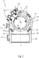
- the turbomolecular pump 111 shown comprises a pump inlet 115 surrounded by an inlet flange 113, to which a recipient, not shown, can be connected in a manner known per se.
- the gas from the recipient can be sucked out of the recipient via the pump inlet 115 and conveyed through the pump to a pump outlet 117, to which a backing pump, such as a rotary vane pump, can be connected.
- the inlet flange 113 forms in accordance with the orientation of the vacuum pump Fig. 1 the upper end of the housing 119 of the vacuum pump 111.
- the housing 119 comprises a lower part 121, on which an electronics housing 123 is arranged on the side. Electrical and / or electronic components of the vacuum pump 111 are accommodated in the electronics housing 123, for example for operating an electric motor 125 arranged in the vacuum pump.
- Several connections 127 for accessories are provided on the electronics housing 123.
- a data interface 129 for example in accordance with the RS485 standard, and a power supply connection 131 are arranged on the electronics housing 123.
- a flood inlet 133 in particular in the form of a flood valve, is provided on the housing 119 of the turbomolecular pump 111, via which the vacuum pump 111 can be flooded.
- a sealing gas connection 135, which is also referred to as a purge gas connection via which purge gas to protect the electric motor 125 (see, for example, FIG Fig. 3 ) before the gas pumped into the engine compartment 137, in which the electric motor 125 is housed in the vacuum pump 111, can be brought.
- two coolant connections 139 are arranged in the lower part 121, one of the coolant connections being provided as an inlet and the other coolant connection being provided as an outlet for coolant, which can be guided into the vacuum pump for cooling purposes.
- the lower side 141 of the vacuum pump can serve as a standing surface, so that the vacuum pump 111 can be operated standing on the underside 141.
- the vacuum pump 111 can also be attached to a recipient via the inlet flange 113 and can thus be operated in a manner of hanging.
- the vacuum pump 111 can be designed so that it can also be operated if it is aligned in a different way than in FIG Fig. 1 is shown.
- Embodiments of the vacuum pump can also be realized, in which the underside 141 cannot be arranged facing downwards, but turned to the side or directed upwards.
- various screws 143 are also arranged, by means of which components of the vacuum pump, which are not further specified here, are fastened to one another.
- a bearing cover 145 is attached to the underside 141.
- Fastening bores 147 are also arranged on the underside 141, via which the pump 111 can be fastened, for example, to a support surface.
- a coolant line 148 is shown in which the coolant introduced and discharged via the coolant connections 139 can circulate.
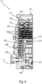
- the vacuum pump comprises a plurality of process gas pump stages for conveying the process gas present at the pump inlet 115 to the pump outlet 117.
- a rotor 149 is arranged in the housing 119 and has a rotor shaft 153 rotatable about an axis of rotation 151.
- the turbomolecular pump 111 comprises a plurality of turbomolecular pump stages connected in series with one another with effective pumping, with a plurality of radial rotor disks 155 attached to the rotor shaft 153 and stator disks 157 arranged between the rotor disks 155 and fixed in the housing 119.
- a rotor disk 155 and an adjacent stator disk 157 each form a turbomolecular one Pump stage.
- the stator disks 157 are held at a desired axial distance from one another by spacer rings 159.
- the vacuum pump also comprises Holweck pump stages which are arranged one inside the other in the radial direction and have a pumping effect and are connected in series with one another.
- the rotor of the Holweck pump stages comprises a rotor hub 161 arranged on the rotor shaft 153 and two cylindrical jacket-shaped Holweck rotor sleeves 163, 165 fastened to and supported by the rotor hub 161, which are oriented coaxially to the axis of rotation 151 and nested one inside the other in the radial direction.
- two cylindrical jacket-shaped Holweck stator sleeves 167, 169 are provided, which are also oriented coaxially to the axis of rotation 151 and are nested one inside the other in the radial direction.
- the pump-active surfaces of the Holweck pump stages are formed by the lateral surfaces, that is to say by the radial inner and / or outer surfaces, of the Holweck rotor sleeves 163, 165 and of the Holweck stator sleeves 167, 169.
- the radial inner surface of the outer Holweck stator sleeve 167 lies against the radial outer surface of the outer Holweck rotor sleeve 163, forming a radial Holweck gap 171 opposite and forms with this the first Holweck pump stage following the turbomolecular pumps.
- the radial inner surface of the outer Holweck rotor sleeve 163 faces the radial outer surface of the inner Holweck stator sleeve 169 with the formation of a radial Holweck gap 173 and forms a second Holweck pump stage with the latter.
- the radial inner surface of the inner Holweck stator sleeve 169 lies opposite the radial outer surface of the inner Holweck rotor sleeve 165, forming a radial Holweck gap 175, and forms the third Holweck pumping stage therewith.
- a radially extending channel can be provided, via which the radially outer Holweck gap 171 is connected to the central Holweck gap 173.
- a radially extending channel can be provided at the upper end of the inner Holweck stator sleeve 169, via which the central Holweck gap 173 is connected to the radially inner Holweck gap 175.
- a connection channel 179 to the outlet 117 can also be provided.
- the aforementioned pump-active surfaces of the Holweck stator sleeves 163, 165 each have a plurality of Holweck grooves running spirally around the axis of rotation 151 in the axial direction, while the opposite lateral surfaces of the Holweck rotor sleeves 163, 165 are smooth and the gas for operating the Drive the vacuum pump 111 in the Holweck grooves.
- a roller bearing 181 is provided in the area of the pump outlet 117 and a permanent magnet bearing 183 in the area of the pump inlet 115.
- a conical spray nut 185 is provided on the rotor shaft 153 with an outer diameter increasing toward the roller bearing 181.
- the injection nut 185 is in sliding contact with at least one scraper of an operating fluid reservoir.
- the operating medium storage comprises a plurality of absorbent disks 187 stacked one on top of the other, which are provided with an operating medium for the rolling bearing 181, e.g. are soaked with a lubricant.
- the operating medium is transferred by capillary action from the operating medium storage via the wiper to the rotating spray nut 185 and, as a result of the centrifugal force along the spray nut 185, is conveyed in the direction of the increasing outer diameter of the spray nut 185 to the roller bearing 181, where it e.g. fulfills a lubricating function.
- the roller bearing 181 and the operating fluid reservoir are enclosed in the vacuum pump by a trough-shaped insert 189 and the bearing cover 145.
- the permanent magnet bearing 183 comprises a bearing half 191 on the rotor side and a bearing half 193 on the stator side, each of which comprises an annular stack of a plurality of permanent magnetic rings 195, 197 stacked on one another in the axial direction.
- the ring magnets 195, 197 lie opposite one another to form a radial bearing gap 199, the rotor-side ring magnets 195 being arranged radially on the outside and the stator-side ring magnets 197 being arranged radially on the inside.
- the magnetic field present in the bearing gap 199 causes magnetic repulsive forces between the ring magnets 195, 197, which cause the rotor shaft 153 to be supported radially.
- the rotor-side ring magnets 195 are carried by a carrier section 201 of the rotor shaft 153, which radially surrounds the ring magnets 195 on the outside.
- the stator-side ring magnets 197 are carried by a stator-side carrier section 203 which extends through the ring magnets 197 and is suspended from radial struts 205 of the housing 119.
- the ring magnets 195 on the rotor side are parallel to the axis of rotation 151 through a cover element coupled to the carrier section 203 207 set.
- the stator-side ring magnets 197 are fixed parallel to the axis of rotation 151 in one direction by a fastening ring 209 connected to the carrier section 203 and a fastening ring 211 connected to the carrier section 203.
- a plate spring 213 can also be provided between the fastening ring 211 and the ring magnet 197.
- An emergency or catch bearing 215 is provided within the magnetic bearing, which runs empty without contact during normal operation of the vacuum pump 111 and only comes into engagement with an excessive radial deflection of the rotor 149 relative to the stator in order to provide a radial stop for the rotor 149 to form, since a collision of the rotor-side structures with the stator-side structures is prevented.
- the catch bearing 215 is designed as an unlubricated roller bearing and forms a radial gap with the rotor 149 and / or the stator, which causes the catch bearing 215 to be disengaged in normal pumping operation.
- the radial deflection at which the catch bearing 215 engages is dimensioned large enough that the catch bearing 215 does not engage during normal operation of the vacuum pump, and at the same time is small enough so that the rotor-side structures collide with the stator-side structures under all circumstances is prevented.
- the vacuum pump 111 comprises the electric motor 125 for rotatingly driving the rotor 149.
- the armature of the electric motor 125 is formed by the rotor 149, the rotor shaft 153 of which extends through the motor stator 217.
- a permanent magnet arrangement can be arranged radially on the outside or embedded on the section of the rotor shaft 153 which extends through the motor stator 217.
- an intermediate space 219 is arranged which comprises a radial motor gap over which the the motor stator 217 and the permanent magnet arrangement for transmitting the drive torque can influence each other magnetically.
- the motor stator 217 is fixed in the housing within the motor space 137 provided for the electric motor 125.
- a sealing gas which is also referred to as a purge gas and which can be, for example, air or nitrogen, can enter the engine compartment 137 via the sealing gas connection 135.
- the electric motor 125 can be used before the process gas, e.g. protected against corrosive parts of the process gas.
- the engine compartment 137 can also be evacuated via the pump outlet 117, i.e. in the engine compartment 137 there is at least approximately the vacuum pressure caused by the backing pump connected to the pump outlet 117.
- a so-called and known labyrinth seal 223 can also be provided between the rotor hub 161 and a wall 221 delimiting the motor space 137, in particular in order to achieve a better seal of the motor space 217 with respect to the radially outside Holweck pump stages.
- a gas analysis system 20 which comprises a vacuum pump 22, a deflection device 24 for a particle beam 26 and an analyzer unit 28.
- the deflection device 24 is set up to split the beam 26 into at least a first partial beam 30 and a second partial beam 32 by the components of the relevant partial beams being deflected to different degrees by the deflection device 24.
- the deflection device 24 is only indicated here by a circle, which symbolizes a magnetic field or electrical field generated by the deflection device 24.
- the molecules In the field of the deflection device 24, the molecules are deflected to different extents, in particular depending on their mass and their charge (at different speeds also depending on this). Uncharged molecules are not distracted and fly straight ahead.
- these molecules form the second partial beam 32, which is shown here and below with dots.
- Charged particles of a certain type are deflected according to the dashed line of the first partial beam 30 and are guided to the analyzer unit 28. It is these particles that are to be detected by the analyzer unit 28.
- the particles of the second partial beam 32 form dirt particles and are not desired in the area of the analyzer unit 28.
- typical particle beams 26 of gas analysis systems usually have more than two constituents, that is to say more than two different types of molecules. Consequently, typically not only two discrete sub-beams 30, 32 are formed, but actually a whole fan of sub-beams is formed.
- This fan largely contains dirt particles, that is to say partial jets, which should not be guided to the analyzer unit 28.
- the aim is to guide as many dirt particles as possible and as many second partial jets, which comprise dirt particles, into a pump-active area 34 of the vacuum pump 22. As a result, the dirt particles are actively removed and contamination of the first partial beam 30 and the area of the analyzer unit 28 is reduced.
- the pump-active area 34 is formed here at least by a first turbo rotor disk 36 in the pumping direction of the vacuum pump 22 and specifically by its rotor blades arranged distributed over the circumference.
- the vacuum pump 22 includes, for example, a plurality of turbo rotor disks 36, generally turbo stages, and a Holweck stage 38.
- the second partial jet 32 is guided parallel to the rotor axis 40 of the vacuum pump 22 and parallel to its pumping direction into the pumping area 34.
- the second partial beam 32 is guided obliquely to the rotor axis 40 into the pumping region 34.
- an aperture 42 for the first partial beam 30 is also indicated, which is connected downstream of the deflection device 24 and further improves the selection of the partial beams.
- the beam 26 is guided into the pump-active area of the pump stage 36, the path of the beam 26 corresponding in particular to that of the second sub-beam 32 or the dotted arrow.
- the particles of the beam 26 or 32 guided into the pump stage 36 are captured directly by the pump stage 36 and advantageously removed, regardless of whether parts of the beam 26 were deflected beforehand.
- FIG. 8 A gas analysis system 20 is shown with a multi-stage vacuum pump 22, the jet 26 or the partial jets 30 and 32 being guided through an intermediate stage area 44.
- the second partial jet 32 is guided into a pump-active area of a turbo rotor disk 36 arranged downstream of the intermediate stage area 44 in the pumping direction.
- the common beam 26 is guided into the intermediate stage area 44 through a first intermediate connection 46.
- the first partial beam 30 emerges from the intermediate stage area 44 through a second intermediate connection 48.
- the deflection device 24 is arranged or effective in the intermediate stage area 44 and there splits the common beam 26 into the partial beams 30, 32.
- the intermediate connection 48 is connected to a chamber 50.
- the analyzer unit 28 is located in this chamber 50 and the first partial beam 30 is guided through the intermediate connection 48 to the analyzer unit 28.
- the chamber 50 is also connected to an inlet 52 of the vacuum pump 22, in this embodiment a further set of turbo rotor disks 54 being arranged at the inlet 52 and the chamber 50 being evacuated.
- the turbo rotor disks 36 and 54 are arranged on a common rotor shaft 56, on which in this example there is also a Holweck rotor of the Holweck pump stage 38.
- the vacuum pump 22 is used on the one hand to improve the separation of the partial beams 30 and 32, in that the molecules of the second partial beam 32 are actively removed and the first partial beam 30 is thus cleaned to a certain extent.
- the vacuum pump 22 also serves to evacuate the chamber 50 in which the analyzer unit 28 is located. This results in an extremely compact design with advantageous analysis accuracy.
- the common beam 26 and the first partial beam 30 are also oriented obliquely with respect to the rotor axis or the rotor shaft 56. Out Fig. 8 it follows that this is also conducive to the compact design.
- the common particle beam 26 can also include molecules that are more strongly charged and / or are lighter than those of the first partial beam 30.
- the common beam 26 can thus include molecules that are deflected even more than the first partial beam 30
- a resulting third partial jet which is not shown in the figures for the sake of clarity, is thus directed through the deflection device 24 against the pumping direction onto the last of the turbo rotor disks 54 in the pumping direction.
- This third sub-beam is thus also directed to a pump-active area, unlike the second sub-beam 32, however, not in the pumping direction, but rather counter to the pumping direction.
- the respective turbo rotor disk 54 or its rotor blades gives the molecules of the third partial jet a preferred direction in the pumping direction, so that these molecules are also actively removed. With these molecules, a collision with the molecules of the first partial beam 30 is then possible. Nevertheless, the probability is reduced overall that the molecules of the third partial beam emerge through the intermediate connection 48 or reach the analyzer unit 28. The analysis result is thus also improved with regard to the third partial beam.
- the third partial jet can also be guided onto a stator disk, which is arranged after the last of the turbo rotor disks 54.
- a stator disk which is arranged after the last of the turbo rotor disks 54.
- no stator disks are shown, but that one is generally advantageously assigned, in particular arranged downstream, to a respective turbo rotor disk.
- a stator disk as disk, which the third partial beam strikes, is fundamentally advantageous in this context, although it does not have an active effect either. Because their the intermediate level area 44 facing surface specifies an advantageous desorption direction distribution for a particle adhering to it, the probability of desorption with a movement component in the pump direction being high.
- Some of these partial beams land on passive components, in particular on an inner wall of the housing. These molecules desorb from the inner wall of the housing with a statistical directional distribution, which is generally unfavorable with regard to the goal of allowing as few dirt particles as possible to reach the analyzer unit 28. It is therefore important to guide as many partial jets and as many molecules as possible, which are different from the first partial jet 30, that is to say as many dirt particles as possible, to a pump-active area of the vacuum pump 22, in particular to the turbo rotor blades.
- the embodiment of the Fig. 9 is the one Fig. 8 Overall similar, but is characterized in that here two deflection devices 24 are provided in the intermediate stage area 44, in contrast to the exemplary only deflection device 24 of the embodiment of FIG Fig. 8 .
- a first deflection device 24 in the direction of the beam 26 separates the partial beams 30 and 32.
- the downstream deflection device 24, on the other hand, is only used for further deflection or further cleaning of the first partial beam 30. In principle, different arrangements of deflection devices are possible.
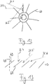
- Fig. 10 is a vacuum pump 22, for example that of the embodiment of FIG Fig. 8 , shown in cross section, the section plane being aligned perpendicular to a rotor shaft 56 and being arranged in particular at the axial height of an intermediate stage region 44.
- a first intermediate connection 46 and a second intermediate connection 48 are provided on the intermediate stage region 44. These are designed separately from one another and are spaced apart in the circumferential direction with respect to the rotor shaft 56.
- a housing wall 58 of the vacuum pump 22 extends in the circumferential direction between the intermediate connections 46 and 48.
- a deflection device 24 is effective between the housing wall 58 and the rotor shaft.
- the intermediate connections 46 and 48 are arranged opposite one another, namely in such a way that a connecting line runs eccentrically past the rotor shaft 56.
- a beam 26 is indicated by a line shown here continuously. Because due to the selected perspective, the first partial beam 30 and the second partial beam 32 are not separately visible here, but lie one above the other. However, it goes without saying that the beam alignment selected here, with the beam plane parallel to the rotor axis or to the rotor shaft 56, is exemplary.
- the common beam 26 enters the intermediate stage area 44 through the first intermediate connection and arrives in the effective area of the deflection device 24. There, the beam 26 is divided into the partial beams 30, 32, the first partial beam 30 through the second intermediate connection 48 from the intermediate stage area 44 is brought out.
- the second partial jet 32 is directed to the pump-active area of the visible turbo rotor disk 36, specifically to the area covered by the plurality of rotor blades 60.
- the direction of rotation of the rotor shaft 56 or of the turbo rotor disk 36 preferably runs here in the clockwise direction.
- FIG. 11 shows a vacuum pump 22 with intermediate connections 46 and 48 at an intermediate stage area 44.
- a respective intermediate connection 46 comprises a flange 62 or 64 for the tight connection of the intermediate connections 46, 48 to further components.
- the flange 62 has a flange plane 66 which extends obliquely to the rotor axis 40.
- the flange 64 also has a flange plane 68 which is oriented obliquely to the rotor axis 40.
- the intermediate connections 46 and 48 are arranged such that no straight line can be laid through the intermediate connections, that is to say that the intermediate connections are not optically transparent.
- the intermediate connections 46 and 48 are arranged in an arrow shape in this embodiment.
- possible angles of the intermediate connections and / or flange planes with respect to the rotor axis will correlate with those of the beams 26 and 30.
- the angles of the intermediate connections and / or flange planes can, however, also lie in a significantly wider angular range, since the actual deflection can possibly take place in the vicinity of the connection plane and thus a largely free choice of angle is possible.
- the vacuum pump 22 has an inlet 52. This can, for example, be connected to a chamber, for example also via a flange.
- the flange plane can, for example, run perpendicular to the rotor axis 40 or also run obliquely.
- the flange plane of the inlet 52 may also be aligned parallel to that of the flange 64 such that the pump 22 with the connections 48 and 52 can advantageously be connected to a chamber housing.
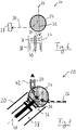
- FIG. 12 A rotor shaft 56 with rotor blades 60 of a turbo rotor disk is shown in cross section. A direction of rotation is indicated counterclockwise. Different aligned second partial beams 32 are indicated by arrows.
- the reference to second partial beams 32 is selected here and below as an example and for easier connection to the examples described above with a deflection device. It is understood that with respect to the 12 to 14 illustrated beam alignment options are generally also valid for a beam, regardless of whether it was previously separated and / or deflected.
- FIG. 12 An entry point into the pumping area is in Fig. 12 each indicated by the arrow end of the dotted arrows.
- a rotor blade 60 is shown for the purpose of illustration exactly in a rotational position corresponding to the entry points.
- the second partial beam 32.1 is guided into the pump-active area such that the partial beam 32.1 has a direction at the entry point which is directed inwards.
- the second partial beam 32.2 is oriented tangentially at the entry point with respect to the rotor shaft 56.
- the partial beam 32.3 is directed outwards at the entry point.
- the partial jet 32.1 enters the pump-active area before it passes the rotor shaft 56 or a point closest to the rotor axis.
- the partial jet 32.3 has passed the rotor shaft 56 before entering the pump-active area.
- the partial jet 32.2 enters the pumping area at the point at which it passes the rotor shaft 56.
- Fig. 13 illustrates further alignment options of a beam, in particular a second partial beam, which illustrate a different perspective and in this respect independently or in combination with the alignments according to Fig. 12 are applicable.
- FIG. 13 A plurality of rotor blades 60 are shown in simplified form in a row, a direction of rotation being indicated by an arrow and extending to the right in the image plane.
- the rotor blades 60 have an angle of attack 69 with respect to the rotor axis 40.
- the second partial beams 32 can be arranged differently with respect to the rotor axis.
- the partial jet 32.4 is aligned parallel to the rotor axis and is generally steeper than the angle of attack of the rotor blades.
- the direction of the second partial jet 32.5 corresponds to the rotor blades 60, that is, it is adjusted accordingly.
- the second partial jet 32.6 is flatter than the rotor blades 46.
- a beam alignment ie a beam alignment with a direction component in the direction of rotation.
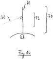
- a radial extension 70 of a rotor blade 60 is shown, which rotates in operation about the rotor axis, which in FIG Fig. 14 runs perpendicular to the image plane.
- the rotor blade 60 extends from a radially inner end, which is defined by a rotor core, a rotor shaft 56 and / or a blade base, to a radially outer end.
- the radial extension 70 forms a pump-active area of the rotor blade 60 or a turbo rotor.
- the second partial beam 32 can be guided onto a radial region 72 of the rotor blades 60, which is spaced from the radially inner end and / or from the radially outer end of the rotor blades by at least a quarter of the radial extent.
- the second partial jet 32 can be guided onto the rotor blades 60 approximately radially in the center or approximately at a third of the radial extent measured from the radially outer end.
- the beam alignment according to the invention enables a particularly high capture probability for the particles of the beam that is guided into the pump-active region, in particular the second partial beam, and in particular for those particles that do not belong to the first partial beam.
- the at least substantially complete pumping speed of the pump stage, in particular the turbo rotor disk comes into play, in the pump-active region of which the jet is guided.
- the active pumping area is advantageously arranged close to the deflection device and thus at the location at which the partial jets are separated. The conductance losses between this location and the pump-active area are therefore small.
- the invention makes it possible to remove a particularly large part of dirt particles particularly effectively and in particular to improve the accuracy of the analysis.
Landscapes
- Engineering & Computer Science (AREA)
- Mechanical Engineering (AREA)
- General Engineering & Computer Science (AREA)
- Chemical & Material Sciences (AREA)
- Analytical Chemistry (AREA)
- Non-Positive Displacement Air Blowers (AREA)
- Other Investigation Or Analysis Of Materials By Electrical Means (AREA)
- Electron Tubes For Measurement (AREA)
Abstract
Vakuumsystem (20), insbesondere Massenspektrometriesystem, umfassend: eine Vakuumpumpe (22) mit einem pumpaktiven Bereich (34), in dem ein Gas mittels eines aktiven Pumpelements (36) förderbar ist, eine Einrichtung zum Erzeugen eines Strahls (26, 32) von zu analysierenden Teilchen, wobei der Strahl (26, 32) in den pumpaktiven Bereich (34) geführt ist.Vacuum system (20), in particular mass spectrometry system, comprising: a vacuum pump (22) with a pump-active area (34) in which a gas can be conveyed by means of an active pump element (36), a device for generating a beam (26, 32) from analyzing particles, the beam (26, 32) being guided into the pumping region (34).
Description
Die vorliegende Erfindung betrifft ein Vakuumsystem, insbesondere Gasanalysesystem und/oder Massenspektrometriesystem, umfassend eine Vakuumpumpe mit einem pumpaktiven Bereich, in dem ein Gas mittels eines aktiven Pumpelements förderbar ist, und eine Einrichtung zum Erzeugen eines Strahls von Teilchen.The present invention relates to a vacuum system, in particular a gas analysis system and / or mass spectrometry system, comprising a vacuum pump with a pump-active area in which a gas can be conveyed by means of an active pump element, and a device for generating a beam of particles.
Teilchenstrahlen werden häufig in Vakuumsystemen erzeugt und genutzt, beispielsweise in Massenspektrometriesystemen. In bekannten Massenspektrometriesystemen werden häufig beispielsweise Umlenkeinrichtungen eingesetzt, mittels denen der Strahl derart umlenkbar ist, dass unterschiedliche Bestandteile des Strahls unterschiedlich abgelenkt werden, sodass wenigstens ein erster und ein zweiter Teilstrahl ausbildbar sind. Diese haben einerseits den Zweck, dass der Teilchenstrahl aufgeteilt wird, sodass nur bestimmte, zu analysierende Bestandteile, die insbesondere den ersten Teilstrahl bilden, in eine gewünschte Richtung, insbesondere zu einer Analysatoreinheit, geführt werden. Übrige Bestandteile, die insbesondere den zweiten Teilstrahl bilden, weisen nach Passage der Umlenkeinrichtung eine andere Richtung als die zu analysierenden Bestandteile auf. Die Umlenkeinrichtung wirkt somit als Filter. Andererseits ermöglicht eine derartige Umlenkung, häufig um etwa 90°, eine kompakte Bauform des Massenspektrometriesystems.Particle beams are often generated and used in vacuum systems, for example in mass spectrometry systems. In known mass spectrometry systems, for example, deflection devices are frequently used, by means of which the beam can be deflected in such a way that different components of the beam are deflected differently, so that at least a first and a second partial beam can be formed. On the one hand, these have the purpose of dividing the particle beam so that only certain components to be analyzed, which in particular form the first partial beam, are guided in a desired direction, in particular to an analyzer unit. The remaining components, which in particular form the second partial beam, have a different direction after the passage of the deflection device than the components to be analyzed. The deflection device thus acts as a filter. On the other hand, such a deflection, often by approximately 90 °, enables a compact design of the mass spectrometry system.
Es ist eine Aufgabe der Erfindung, bei einem Vakuumsystem der eingangs genannten Art die Evakuierung im Bereich des Strahls zu verbessern.It is an object of the invention to improve the evacuation in the region of the beam in a vacuum system of the type mentioned at the outset.
Diese Aufgabe wird durch ein Vakuumsystem nach Anspruch 1 gelöst, und insbesondere dadurch, dass der Strahl in den pumpaktiven Bereich der Vakuumpumpe geführt ist.This object is achieved by a vacuum system according to claim 1, and in particular in that the jet is guided into the pump-active area of the vacuum pump.
Hierdurch wird der Strahl bzw. werden dessen Moleküle direkt abgepumpt und die Evakuierung wird verbessert. Bei dem in den pumpaktiven Bereich geführten Strahl kann es sich z.B. um einen Teilstrahl nach Passage einer Filter- und/oder Separierungseinrichtung handeln. Generell wird hier aber ausgenutzt, dass der Strahl einen Teilchenstrom mit einer bestimmten Richtung aufweist und dass diese Richtung vorteilhaft ausgenutzt wird, um die Teilchen direkt einzufangen. Insoweit kann es sich auch beispielsweise um eine Art Hauptstrahl und/oder einen Gesamtstrahl handeln. Allgemein ist die Erfindung darauf gerichtet, die Einfangwahrscheinlichkeit eines jeweiligen Teilchens des Strahls zu erhöhen. Dies wird auf konstruktiv besonders einfache Weise durch die Erfindung erreicht.As a result, the jet or its molecules are pumped off directly and the evacuation is improved. The jet directed into the pump-active area can e.g. act as a partial beam after passage through a filter and / or separation device. In general, however, use is made of the fact that the beam has a particle stream with a specific direction and that this direction is advantageously used in order to capture the particles directly. In this respect, it can also be a type of main beam and / or an overall beam, for example. In general, the invention is directed to increasing the probability of capturing a particular particle of the beam. This is achieved in a structurally particularly simple manner by the invention.
Bevorzugt kann das Vakuumsystem eine Umlenkeinrichtung umfassen, mittels derer der Strahl derart umlenkbar ist, dass unterschiedliche Bestandteile des Strahls unterschiedlich abgelenkt werden, sodass wenigstens ein erster und ein zweiter Teilstrahl ausbildbar sind, wobei der zweite Teilstrahl in den pumpaktiven Bereich geführt ist. Allgemein ist der Strahl also insbesondere zumindest teilweise in den pumpaktiven Bereich geführt. Insoweit nachfolgend von dem Strahl die Rede ist, versteht es sich, dass auch ein, insbesondere zweiter, Teilstrahl gemeint sein kann.The vacuum system can preferably comprise a deflection device, by means of which the beam can be deflected such that different components of the beam are deflected differently, so that at least a first and a second partial beam can be formed, the second partial beam being guided into the pump-active area. In general, the jet is therefore at least partially guided into the pump-active area. Insofar as the jet is mentioned below, it goes without saying that a, in particular second, partial jet can also be meant.
Die Möglichkeit der Kontamination des ersten Teilstrahls durch Moleküle des zweiten Teilstrahls ist besonders gering. Die Erfindung ermöglich in diesem Zusammenhang also insbesondere eine gute Separierung der Teilstrahlen und eine hohe Qualität des ersten Teilstrahls, die sich beispielsweise positiv auf eine Analyse des ersten Teilstrahls auswirken kann.The possibility of contamination of the first partial beam by molecules of the second partial beam is particularly low. In this context, the invention thus enables in particular good separation of the partial beams and high quality of the first partial beam, which can, for example, have a positive effect on an analysis of the first partial beam.
Die Gasbestandteile des zweiten Teilstrahls sind häufig solche Bestandteile, die im Hinblick auf eine Analyseaufgabe unerwünscht sind, also unerwünschte Moleküle darstellen. Diese können als Schmutzpartikel bezeichnet werden. Bei Umlenkeinrichtungen des Standes der Technik landen zweite Teilstrahlen bzw. Schmutzpartikel typischerweise an statischen Bauteilen im Bereich der oder benachbart zur Umlenkeinrichtung. Auch wird häufig der Umlenkeinrichtung nachgeschaltet eine Blende angeordnet, durch die der erste Teilstrahl passieren kann, auf deren Oberfläche abseits des ersten Teilstrahls bzw. eines Durchgangs hierfür aber die Schmutzpartikel auftreffen. Alle Schmutzpartikel, die auf statischen Oberflächen landen, desorbieren nach einer gewissen Zeit wieder von der betreffenden Oberfläche mit einer statistischen Verteilung der Richtung. Dies bedeutet einerseits eine erhöhte Wahrscheinlichkeit, dass Schmutzpartikel trotz aller Filtereinrichtungen zur Analysatoreinheit gelangen. Andererseits können die Schmutzpartikel mit zu analysierenden Gasmolekülen des ersten Teilstrahls kollidieren und so dessen Qualität verringern. Denn die Moleküle des ersten Teilstrahl werden hierdurch abgelenkt und die Anzahl derjenigen zu analysierenden Moleküle, die die Analysatoreinheit erreichen, wird reduziert.The gas components of the second partial beam are often those components that are undesirable with regard to an analysis task, that is to say represent undesired molecules. These can be called dirt particles. In the case of deflection devices of the prior art, second partial jets or dirt particles typically land on static components in the region of or adjacent to the deflection device. A diaphragm is also often arranged downstream of the deflection device, through which the first partial jet can pass, but on the surface of which the dirt particles impinge apart from the first partial jet or a passage for this. All dirt particles that land on static surfaces desorb after a certain time from the surface in question with a statistical distribution of the direction. On the one hand, this means an increased probability that dirt particles will reach the analyzer unit despite all filter devices. On the other hand, the dirt particles can collide with the gas molecules of the first partial jet to be analyzed, thus reducing its quality. This is because the molecules of the first partial beam are thereby deflected and the number of molecules to be analyzed that reach the analyzer unit is reduced.
Die Erfindung ermöglicht nun, dass Schmutzpartikel unmittelbar durch die Pumpwirkung der Vakuumpumpe abgeführt werden. Dabei wird vorteilhaft die Richtung bzw. kinetische Energie der Schmutzpartikel im Teilchenstrahl ausgenutzt, um diese aktiv dem pumpaktiven Bereich der Vakuumpumpe zuzuführen. Durch den pumpaktiven Bereich wird den Schmutzpartikeln bzw. dem zweiten Teilstrahl sodann aktiv eine Vorzugsrichtung in Pumprichtung verliehen, sodass die Schmutzpartikel aktiv von dem ersten Teilstrahl und insbesondere von einer Analysatoreinheit weggeführt werden. Im Stand der Technik ist eine wirksame Evakuierung von Vakuumkammern eines Gasanalysesystems häufig schwierig, nämlich durch nachteilige Geometrien und Leitwerte. Eine bessere Evakuierung ermöglicht jedoch eine bessere Analysegenauigkeit. Die Erfindung ermöglicht durch die Ausnutzung der Strahlrichtung bzw. der kinetischen Energie der Teilchen und durch die aktive Abführung eine bessere Evakuierung und somit insbesondere eine verbesserte Analysegenauigkeit.The invention now enables dirt particles to be removed directly by the pumping action of the vacuum pump. The direction or kinetic energy of the dirt particles in the particle beam is advantageously used in order to actively supply them to the pump-active area of the vacuum pump. The pump-active area then actively gives the dirt particles or the second partial jet a preferred direction in the pumping direction, so that the dirt particles are actively guided away from the first partial jet and in particular from an analyzer unit. In the prior art, effective evacuation of vacuum chambers in a gas analysis system is often difficult, namely due to disadvantageous geometries and conductance values. However, better evacuation enables better analytical accuracy. The invention enables the use of the beam direction or the kinetic energy of the particles and better evacuation and thus, in particular, improved analysis accuracy due to active evacuation.
Als pumpaktiver Bereich ist allgemein ein Wirkbereich eines aktiven Pumpelements der Vakuumpumpe, zum Beispiel eines Rotors oder Rotorelements, insbesondere einer Turborotorscheibe, zu verstehen. Im Falle eines Rotors wird der Strahl, insbesondere der zweite Teilstrahl, insbesondere in einen aktiven Rotorbereich geführt. Bei einer Turbomolekularvakuumpumpe bzw. Turborotorscheibe ist dies insbesondere ein von den Rotorschaufeln im Betrieb überstrichener Bereich. Insbesondere gehört ein Rotorkern, der selbst keine pumpaktive Wirkung aufweist, sondern lediglich strukturelle Funktion hat, nicht zum pumpaktiven Bereich. Allgemein vorteilhaft ist der Strahl nicht auf einen Rotorkern geführt bzw. ist der Strahl an einem Rotorkern vorbeigeführt.A pump-active area is generally to be understood as an active area of an active pump element of the vacuum pump, for example a rotor or rotor element, in particular a turbo-rotor disk. In the case of a rotor, the jet, in particular the second partial jet, is guided in particular into an active rotor area. In the case of a turbomolecular vacuum pump or turbo rotor disk, this is, in particular, an area swept by the rotor blades during operation. In particular, a rotor core, which itself has no pump-active effect but only has a structural function, does not belong to the pump-active area. The beam is generally not advantageously guided onto a rotor core or the beam is guided past a rotor core.
Die Umlenkeinrichtung lenkt unterschiedliche Bestandteile des Teilchenstrahls unterschiedlich ab. Dabei werden typischerweise auch bestimmte Bestandteile gar nicht abgelenkt, nämlich insbesondere ungeladene Bestandteile. Allgemein gilt also, dass wenigstens einer von erstem und zweitem Teilstrahl durch die Umlenkeinrichtung umgelenkt werden muss, um die Teilstrahlen in solche aufzuteilen. Zum Beispiel kann der zweite Teilstrahl nicht durch die Umlenkeinrichtung umgelenkt sein bzw. in Fortführung des Teilchenstrahls vor der Umlenkeinrichtung ausgerichtet sein. Ungeladene Teilchen bilden besonders häufig unerwünschte Moleküle bzw. Schmutzpartikel im Hinblick auf die Analyseaufgabe. Wenn der Teilstrahl ungeladener Bestandteile in den pumpaktiven Bereich geführt wird, wird also insbesondere ein besonders großer Anteil an Schmutzpartikeln direkt abgeführt.The deflection device deflects different components of the particle beam differently. Certain components are typically not distracted at all, namely in particular uncharged components. The general rule is that at least one of the first and second partial beams has to be deflected by the deflection device in order to divide the partial beams into those. For example, the second partial beam cannot be deflected by the deflection device or can be aligned in front of the deflection device in continuation of the particle beam. Uncharged particles particularly frequently form undesired molecules or dirt particles with regard to the analysis task. If the partial jet of uncharged components is directed into the pump-active area, a particularly large proportion of dirt particles is thus removed directly.
Die Moleküle des Strahls, der in den pumpaktiven Bereich geführt ist, werden insbesondere unmittelbar von wenigstens einem pumpaktiven Element der Vakuumpumpe im pumpaktiven Bereich eingefangen. Im Zusammenhang mit einem als Turborotor ausgebildeten pumpaktiven Element bedeutet dies insbesondere, dass die Moleküle des Strahls den von den Rotorschaufeln überstrichenen Bereich durchtreten und anschließend durch das allgemein bekannte Wirkprinzip des Turborotors stromabwärts derselben "gehalten" werden, dass also - physikalisch betrachtet - die Wahrscheinlichkeit verringert wird, dass ein jeweiliges Molekül zurück in den Bereich stromaufwärts der Rotorschaufeln gelangt.The molecules of the jet, which is guided into the pump-active area, are in particular captured directly by at least one pump-active element of the vacuum pump in the pump-active area. In connection with an as This means, in particular, a pump-active element designed as a turbo rotor that the molecules of the jet pass through the area swept by the rotor blades and are subsequently "held" downstream by the generally known operating principle of the turbo rotor, that is, from a physical point of view, the probability that a respective one is reduced Molecule gets back into the area upstream of the rotor blades.
Verschiedene Teilstrahlen umfassen nach Passage einer Umlenkeinrichtung allgemein unterschiedliche Bestandteile und weisen unterschiedliche Richtungen auf. Dabei weist ein Teilstrahl nicht notwendigerweise nur einen Bestandteil bzw. eine Teilchenart auf. Insbesondere der zweite Teilstrahl kann zum Beispiel eine Vielzahl von Bestandteilen aufweisen, die allesamt Schmutzpartikel bilden können. Dies gilt insbesondere für einen zweiten Teilstrahl, der in Bezug auf den gemeinsamen Strahl vor Passage der Umlenkeinrichtung geradeaus gerichtet ist und/oder ungeladene Moleküle aufweist. Jedoch kann auch der erste Teilstrahl grundsätzlich unterschiedliche Bestandteile aufweisen, wobei die Unterschiede typischerweise klein sind.After passing through a deflection device, different partial beams generally comprise different components and have different directions. A partial beam does not necessarily have only one component or one type of particle. In particular, the second partial jet can, for example, have a large number of constituents, all of which can form dirt particles. This applies in particular to a second partial beam, which is directed straight ahead with respect to the common beam before passing the deflection device and / or has uncharged molecules. However, the first partial beam can also have fundamentally different components, the differences typically being small.
Zudem versteht es sich, dass die Umlenkeinrichtung den gemeinsamen Teilchenstrahl typischerweise nicht in lediglich zwei absolut diskrete Teilstrahlen aufteilt. Vielmehr weisen Teilchenstrahlen in derartigen Systemen typischerweise eine Vielzahl von Bestandteilen auf, wobei meist lediglich ein kleiner Teil der Bestandteile analysiert werden soll, häufig eine bestimmte lonen- und/oder Molekülart. Folglich bilden sich nach Passage der Umlenkeinrichtung typischerweise eine Vielzahl von, insbesondere zweiten, Teilstrahlen fächerartig aus. Grundsätzlich kann insbesondere wenigstens ein zweiter Teilstrahl in den pumpaktiven Bereich geführt sein, vorteilhaft werden aber mehrere zweite Teilstrahlen bzw. Teilstrahlen mit Schmutzpartikeln in den pumpaktiven Bereich geführt, um möglichst viele Schmutzpartikel direkt abzuführen. Wie viele zweite Teilstrahlen in den pumpaktiven Bereich geführt werden können und welcher Winkelbereich des Fächers von Teilstrahlen in den pumpaktiven Bereich geführt werden kann, ist insbesondere von den geometrischen Gegebenheiten in der Vakuumpumpe abhängig. Grundsätzlich können also auch mehr als zwei Teilstrahlen ausgebildet werden, z.B. mehrere erste, nicht in den pumpaktiven Bereich hineingeführte und/oder mehrere zweite, in den pumpaktiven Bereich hineingeführte Teilstrahlen.In addition, it goes without saying that the deflection device typically does not split the common particle beam into only two absolutely discrete partial beams. Rather, particle beams in such systems typically have a large number of constituents, usually only a small part of the constituents being to be analyzed, frequently a specific type of ion and / or molecule. Consequently, after the deflection device has passed, a plurality of, in particular second, partial beams typically form a fan-like pattern. In principle, at least one second partial jet can in particular be guided into the pump-active area, but several second partial jets or partial jets with dirt particles are advantageously guided into the pump-active area in order to directly remove as many dirt particles as possible. How many second partial beams can be guided into the active pumping area and which angular area of the fan from Partial jets can be guided into the active pumping area is particularly dependent on the geometric conditions in the vacuum pump. In principle, therefore, more than two partial beams can also be formed, for example a plurality of first partial beams that are not led into the pump-active region and / or several second partial beams that are led into the pump-active region.
Der zweite Teilstrahl kann insbesondere ungeladene Teilchen und/oder Teilchen eines Trägergases aufweisen oder im Wesentlichen aus solchen bestehen. Häufig macht ein Trägergas einen Großteil des Drucks in einem Vakuumsystem, insbesondere Massenspektrometriesystem, aus. Entsprechend kann durch die Erfindung vorteilhaft ein großer Anteil von Teilchen, die nicht Teil des ersten Teilstrahls sein sollen, direkt abgepumpt werden. Bei einem Trägergas handelt es sich beispielsweise um ein Inertgas und/oder Luft. Z.B. kann als Trägergas Helium eingesetzt werden. Wenn Luft das Trägergas bildet, umfasst der zweite Teilstrahl beispielsweise Sauerstoff und/oder Stickstoff, insbesondere ungeladene Teilchen hiervon. Allgemein umfasst der zweite Teilstrahl insbesondere hauptsächlich eine Molekülart und/oder weist einen vielfach höheren Teilchenstrom auf als der erste Teilchenstrahl. Typischerweise macht eine zu analysierende Molekülart in einem Gasanalysesystem, insbesondere Massenspektrometer, nur einen kleinen Teil des Gasstromes aus und/oder ein Trägergas macht einen weit überwiegenden Teil aus.The second partial jet can in particular have or consist essentially of uncharged particles and / or particles of a carrier gas. A carrier gas often makes up a large part of the pressure in a vacuum system, in particular mass spectrometry system. Accordingly, the invention advantageously allows a large proportion of particles which are not intended to be part of the first partial jet to be pumped off directly. A carrier gas is, for example, an inert gas and / or air. E.g. can be used as a carrier gas helium. If air forms the carrier gas, the second partial jet comprises, for example, oxygen and / or nitrogen, in particular uncharged particles thereof. In general, the second partial beam mainly comprises one type of molecule and / or has a particle flow that is many times higher than the first particle beam. Typically, a type of molecule to be analyzed in a gas analysis system, in particular mass spectrometer, only makes up a small part of the gas stream and / or a carrier gas makes up a vast majority.
Ein wichtiger Gedanke der Erfindung im Zusammenhang mit der Umlenkeinrichtung besteht also darin, dass Gasbestandteile unterschiedlich abgelenkt werden und ein möglichst großer Teil von, insbesondere im Hinblick auf eine Analyseaufgabe unerwünschten, Gasbestandteilen unter Ausnutzung ihrer Richtung direkt in den pumpaktiven Bereich geführt wird. So können diese, insbesondere unerwünschten, Bestandteile aktiv abgeführt werden, nämlich insbesondere aus dem Bereich des ersten Teilstrahls heraus und beispielsweise weg von einem Analysebereich bzw. einem Bereich einer Analysatoreinheit.An important idea of the invention in connection with the deflection device is therefore that gas components are deflected differently and that as large a part as possible of gas components which are undesirable, in particular with regard to an analysis task, is led directly into the pump-active area using their direction. In this way, these, in particular undesirable, components can be actively removed, namely in particular out of the area of the first partial beam and, for example, away from an analysis area or an area of an analyzer unit.
Die Umlenkeinrichtung teilt den Teilchenstrahl in Teilstrahlen auf. Dabei wird der Strahl vor Passage der Umlenkeinrichtung hier auch als gemeinsamer (Teilchen-) Strahl bezeichnet, dies in Abgrenzung zu den Teilstrahlen, die sich bei und/oder nach Passage der Umlenkeinrichtung ausbilden.The deflection device divides the particle beam into partial beams. Here, the beam before passing the deflection device is also referred to here as a common (particle) beam, in delimitation to the partial beams which form during and / or after passage of the deflection device.
Grundsätzlich kann das Vakuumsystem beispielsweise auch mehrere Umlenkeinrichtungen, zum Beispiel jeweils mit vorteilhafter Führung eines Teilstrahls in einen pumpaktiven Bereich einer Vakuumpumpe, aufweisen. Allgemein können, beispielsweise auch neben einer Umlenkeinrichtung, auch verschiedenste andere Filterelemente zum Einsatz kommen, wie zum Beispiel eine Blende und/oder ein Quadrupol.In principle, the vacuum system can, for example, also have a plurality of deflection devices, for example, each with an advantageous guidance of a partial jet into a pump-active area of a vacuum pump. In general, in addition to a deflection device, for example, a wide variety of other filter elements can also be used, such as an aperture and / or a quadrupole.
Gemäß einer Ausführungsform ist vorgesehen, dass der Strahl zumindest mit einer Richtungskomponente in Pumprichtung in den pumpaktiven Bereich geführt ist. Hierdurch wird die Pumpwirkung des pumpaktiven Bereichs unterstützt und die Moleküle des Strahls werden besonders wirksam abgeführt.According to one embodiment, it is provided that the beam is guided into the pump-active region with at least one directional component in the pumping direction. This supports the pumping action of the pumping area and the molecules of the jet are discharged particularly effectively.
Insbesondere kann es vorgesehen sein, dass der erste Teilstrahl nicht in den pumpaktiven Bereich geführt ist. Alternativ oder zusätzlich kann der erste Teilstrahl zu einem Bereich außerhalb der Vakuumpumpe geführt sein. Insbesondere kann der erste Teilstrahl zu einer Analysatoreinheit geführt sein, beispielsweise direkt oder durch wenigstens ein weiteres Filterelement, insbesondere eine Blende, hindurch. Grundsätzlich kann der erste Teilstrahl an einem Gehäuse der Vakuumpumpe vorbei oder durch ein solches hindurchgeführt sein.In particular, it can be provided that the first partial jet is not guided into the pump-active area. Alternatively or additionally, the first partial jet can be guided to an area outside the vacuum pump. In particular, the first partial beam can be guided to an analyzer unit, for example directly or through at least one further filter element, in particular an aperture. In principle, the first partial jet can pass a housing of the vacuum pump or be guided through one.
Allgemein kann die Vakuumpumpe einen Rotor umfassen, der zur Rotation um eine Rotorachse antreibbar ist. Ein aktives Pumpelement der Vakuumpumpe bzw. des pumpaktiven Bereichs kann mit dem Rotor gekoppelt sein, sodass der Rotor das Pumpelement antreibt. Der Strahl kann insbesondere in einen aktiven Rotorbereich des Rotors bzw. des aktiven Pumpelements geführt sein.In general, the vacuum pump can comprise a rotor which can be driven to rotate about a rotor axis. An active pump element of the vacuum pump or the pump-active area can be coupled to the rotor, so that the rotor drives the pump element. The beam can in particular be guided into an active rotor area of the rotor or of the active pump element.
Gemäß einer weiteren Ausführungsform ist vorgesehen, dass eine Pumprichtung und/oder eine Rotorachse eines aktiven Pumpelements und/oder der Vakuumpumpe schräg in Bezug auf eine Richtung des Strahls, insbesondere vor Passage einer oder der Umlenkeinrichtung, ausgerichtet ist. Hierdurch kann der Strahl und insbesondere ein in Bezug auf einen gemeinsamen Strahl geradeaus gerichteter, zweiter Teilstrahl besonders vorteilhaft im Hinblick auf die Pumpwirkung in den pumpaktiven Bereich geführt werden. Zudem ist eine derartige Anordnung im Hinblick auf den Bauraum besonders vorteilhaft. Insbesondere kann ein Winkel zwischen einer Pumprichtung und/oder einer Rotorachse des aktiven Pumpelements und/oder der Vakuumpumpe und einer Richtung des Strahls, insbesondere vor Passage einer oder der Umlenkeinrichtung, im Bereich von 40° bis 60° liegen, bevorzugt im Bereich von 50° bis 55°. Diese Werte werden durch die Teilchengeschwindigkeit, die Rotorschaufelumlaufgeschwindigkeit im "Zielbereich" des Strahls und den dortigen Rotorschaufelwinkel bzw. Anstellwinkel beeinflusst. Der Winkel kann fallbezogen dreidimensional optimiert werden.According to a further embodiment, it is provided that a pumping direction and / or a rotor axis of an active pump element and / or the vacuum pump is oriented obliquely with respect to a direction of the jet, in particular before passage of one or the deflection device. As a result, the jet and in particular a second partial jet directed straight ahead with respect to a common jet can be guided into the pump-active region particularly advantageously with regard to the pumping action. In addition, such an arrangement is particularly advantageous with regard to the installation space. In particular, an angle between a pumping direction and / or a rotor axis of the active pump element and / or the vacuum pump and a direction of the jet, in particular before passage through one or the deflection device, can be in the range from 40 ° to 60 °, preferably in the range of 50 ° up to 55 °. These values are influenced by the particle speed, the rotor blade revolution speed in the "target area" of the beam and the rotor blade angle or angle of attack there. The angle can be optimized three-dimensionally depending on the case.
Bevorzugt kann eine Pumprichtung und/oder eine Rotorachse des aktiven Pumpelements und/oder der Vakuumpumpe schräg in Bezug auf eine Richtung des ersten und/oder des zweiten Teilstrahls nach Passage der Umlenkeinrichtung ausgerichtet sein. Auch dies ist förderlich für eine kompakte Bauweise.A pumping direction and / or a rotor axis of the active pump element and / or the vacuum pump can preferably be oriented obliquely with respect to a direction of the first and / or the second partial jet after passage of the deflection device. This is also conducive to a compact design.
Allgemein kann die Vakuumpumpe beispielsweise ein- oder mehrstufig ausgebildet sein. Mehrstufig bedeutet, dass die Vakuumpumpe wenigstens zwei Pumpstufen aufweist. Wenigstens zwei Pumpstufen können bevorzugt in Reihe geschaltet sein. Die Pumpstufen können beispielsweise durch einen gemeinsamen Rotor angetrieben sein.In general, the vacuum pump can be designed in one or more stages, for example. Multi-stage means that the vacuum pump has at least two pump stages. At least two pump stages can preferably be connected in series. The pump stages can be driven by a common rotor, for example.
Bei einer Ausführungsform ist vorgesehen, dass die Vakuumpumpe wenigstens zwei, bevorzugt in Reihe geschaltete, Pumpstufen aufweist, wobei, insbesondere in Pumprichtung, zwischen den Pumpstufen ein Zwischenstufenbereich angeordnet ist. Über diesen Zwischenstufenbereich können die Pumpstufen insbesondere beabstandet sein. Der Strahl ist bevorzugt durch den Zwischenstufenbereich geführt. Grundsätzlich kann der Strahl, insbesondere ein zweiter Teilstrahl, in eine Pumpstufe geführt sein, die insbesondere in Pumprichtung stromabwärts des Zwischenstufenbereichs angeordnet ist. Somit werden einerseits eine besonders kompakte Bauform und andererseits eine besonders gute Abführung der Teilchen, insbesondere von Schmutzpartikeln, ermöglicht.In one embodiment it is provided that the vacuum pump has at least two pump stages, preferably connected in series, an intermediate stage region being arranged between the pump stages, in particular in the pumping direction. The pump stages can in particular be spaced apart via this intermediate stage region. The beam is preferably passed through the intermediate stage area. In principle, the jet, in particular a second partial jet, can be guided into a pump stage, which is arranged downstream of the intermediate stage region, in particular in the pumping direction. This enables on the one hand a particularly compact design and on the other hand a particularly good removal of the particles, in particular dirt particles.
Eine Pumpstufe ist insbesondere durch ein aktives Pumpelement definiert, insbesondere in Zusammenwirkung mit einem statischen und/oder passiven Element. Bei einer Turbomolekularpumpe bildet somit eine umfängliche Reihe von Rotorschaufeln, insbesondere einer Turborotorscheibe, insbesondere in Zusammenwirkung mit einer Statorscheibe, eine Pumpstufe. In diesem Zusammenhang sei erwähnt, dass ein Turborotor grundsätzlich beispielsweise mit mehreren einteilig verbundenen Schaufelreihen ausgeführt sein kann und/oder ein oder mehrere Turborotorscheiben aufweisen kann.A pump stage is defined in particular by an active pump element, in particular in cooperation with a static and / or passive element. In the case of a turbomolecular pump, an extensive row of rotor blades, in particular a turbo rotor disk, in particular in cooperation with a stator disk, forms a pump stage. In this context it should be mentioned that a turbo rotor can in principle be designed, for example, with a plurality of rows of blades connected in one piece and / or can have one or more turbo rotor disks.
Der Strahl kann allgemein bevorzugt in den Wirkbereich des aktiven Pumpelements und/oder auf ein drehendes Element, beispielsweise eine Turborotorscheibe, gerichtet sein.The beam can generally be directed preferably into the active region of the active pump element and / or onto a rotating element, for example a turbo rotor disk.
Der erste Teilstrahl kann bevorzugt nach Passage des Zwischenstufenbereichs und/oder einer Umlenkeinrichtung aus der Vakuumpumpe herausgeführt sein, beispielsweise zu einer Analysatoreinheit. Allgemein kann eine Analysatoreinheit zum Beispiel als Detektor ausgebildet sein.The first partial beam can preferably be led out of the vacuum pump after passage of the intermediate stage area and / or a deflection device, for example to an analyzer unit. In general, an analyzer unit can be designed, for example, as a detector.
Gemäß einer Weiterbildung ist vorgesehen, dass die Vakuumpumpe am Zwischenstufenbereich einen ersten Zwischenanschluss zum Eintritt des Strahls in den Zwischenstufenbereich und/oder einen zweiten Zwischenanschluss zum Austritt des ersten Teilstrahls aus dem Zwischenstufenbereich aufweist. Der erste und/oder der zweite Zwischenanschluss können beispielsweise einen, insbesondere eigenen, Flansch aufweisen.According to a further development, it is provided that the vacuum pump has a first intermediate connection at the intermediate stage area for the entry of the jet into the intermediate stage area and / or a second intermediate connection for exit of the first partial jet from the intermediate stage area. The first and / or the second intermediate connection can have, for example, a flange, in particular its own.
Die Zwischenanschlüsse können bevorzugt, insbesondere in Bezug auf eine Rotorachse und/oder Pumprichtung, zumindest im Wesentlichen gegenüberliegend voneinander angeordnet sein. Der, insbesondere gemeinsame, Strahl und/oder der erste Teilstrahl können somit vorteilhaft in den Zwischenstufenbereich eintreten bzw. hieraus austreten. Die Zwischenanschlüsse sind aber nicht notwendigerweise exakt radial gegenüberliegend, d. h. um 180° um die Rotorachse versetzt, angeordnet. Bevorzugt ist hingegen eine außermittige Verbindungsachse der Zwischenanschlüsse, die insbesondere an einem Rotorkern vorbeiführt. Hierdurch wird eine besonders vorteilhafte Gasführung ermöglicht. Gleichwohl sind radial gegenüberliegende Zwischenanschlüsse grundsätzlich möglich, insbesondere in Verbindung mit einer Umlenkeinrichtung, die den Gasstrahl zumindest teilweise um einen Rotorkern herum umlenkt.The intermediate connections can preferably be arranged at least essentially opposite one another, in particular with respect to a rotor axis and / or pump direction. The, in particular common, beam and / or the first partial beam can thus advantageously enter or exit the intermediate stage area. However, the intermediate connections are not necessarily exactly radially opposite, i.e. H. offset by 180 ° around the rotor axis. In contrast, an eccentric connecting axis of the intermediate connections, which in particular leads past a rotor core, is preferred. This enables a particularly advantageous gas flow. Nevertheless, radially opposite intermediate connections are possible in principle, in particular in connection with a deflection device which at least partially deflects the gas jet around a rotor core.
Bevorzugt können die Zwischenanschlüsse separat voneinander ausgebildet und/oder in Umfangsrichtung beabstandet angeordnet sein. Dabei erstreckt sich vorzugsweise eine Gehäusewand in Umfangsrichtung zwischen den Zwischenanschlüssen, insbesondere über wenigstens 20°, bevorzugt wenigstens 35°. Durch die Trennung der Zwischenanschlüsse wird die Güte des ersten Teilstrahls weiter verbessert.The intermediate connections can preferably be formed separately from one another and / or be spaced apart in the circumferential direction. In this case, a housing wall preferably extends in the circumferential direction between the intermediate connections, in particular over at least 20 °, preferably at least 35 °. The quality of the first partial beam is further improved by the separation of the intermediate connections.
Eine Umlenkeinrichtung kann beispielsweise ein magnetisches und/oder elektrisches Feld aufweisen. Ein magnetisches Feld kann beispielsweise durch einen Dauermagneten oder zum Beispiel auch durch einen Elektromagneten bereitgestellt werden. Ein magnetisches und/oder elektrisches Feld bewirkt die unterschiedliche Ablenkung von geladenen Teilchen, insbesondere in Abhängigkeit von ihrer Masse. Entsprechend kann die Umlenkeinrichtung eine Felderzeugungseinrichtung aufweisen, wie z.B. einen Magneten oder eine Elektrode.A deflection device can have a magnetic and / or electric field, for example. A magnetic field can be provided, for example, by a permanent magnet or, for example, also by an electromagnet will. A magnetic and / or electric field causes the different deflection of charged particles, in particular depending on their mass. Correspondingly, the deflection device can have a field generating device, such as a magnet or an electrode.
Die Umlenkeinrichtung kann bevorzugt im oder am Zwischenstufenbereich wirksam und/oder angeordnet sein. Der Begriff "wirksam" bezieht sich insbesondere auf das elektrische und/oder magnetische Feld der Umlenkeinrichtung, also allgemein auf ihren Wirkbereich. Die Umlenkeinrichtung kann beispielsweise auch Komponenten, wie z.B. eine Felderzeugungseinrichtung, außerhalb ihres Wirkbereichs aufweisen. Folglich bezieht sich der Begriff "angeordnet" zumindest auch auf den Wirkbereich der Umlenkeinrichtung. Insbesondere kann ein elektrisches und/oder magnetisches Feld der Umlenkeinrichtung im und oder am Zwischenstufenbereich angeordnet sein. Alternativ oder zusätzlich kann eine Umlenkeinrichtung bzw. ein elektrisches und/oder magnetisches Feld beispielsweise auch radial außerhalb des Zwischenstufenbereichs, beispielsweise am oder im Bereich eines Zwischenanschlusses, insbesondere desjenigen Zwischenanschlusses zum Eintritt des gemeinsamen Strahls, angeordnet sein.The deflection device can preferably be effective and / or arranged in or on the intermediate stage area. The term "effective" refers in particular to the electrical and / or magnetic field of the deflection device, that is to say generally to its effective range. The deflection device can also, for example, components such as have a field generating device outside its effective range. Consequently, the term "arranged" at least also refers to the effective range of the deflection device. In particular, an electrical and / or magnetic field of the deflection device can be arranged in and or at the intermediate stage area. Alternatively or additionally, a deflection device or an electrical and / or magnetic field can also be arranged, for example, radially outside the intermediate stage area, for example on or in the area of an intermediate connection, in particular of that intermediate connection for the entry of the common beam.
Die Anordnung einer, insbesondere (elektro-)magnetischen, Umlenkeinrichtung im Bereich wenigstens eines der Zwischenanschlüsse ist ebenfalls vorteilhaft möglich. Sowohl eine Anordnung von passiven und/oder permanentmagnetischen als auch von aktiven Umlenkelementen ist einerseits im Vakuumbereich oder andererseits auch außerhalb des Vakuumbereichs bzw. in Atmosphäre möglich. So kann eine Umlenkeinrichtung bzw. ein Umlenkelement z.B. im Bereich des Pumpengehäuses und/oder außen am Pumpengehäuse angeordnet werden. Grundsätzlich kann auch die Umlenkeinrichtung selbst außerhalb des Vakuumbereichs derart angeordnet sein, dass sie im Vakuumbereich wirksam ist, dass sich also insbesondere ein elektrisches und/oder magnetisches Feld in den Vakuumbereich, insbesondere in den Zwischenstufenbereich, erstreckt.The arrangement of a, in particular (electro) magnetic, deflection device in the region of at least one of the intermediate connections is likewise advantageously possible. An arrangement of passive and / or permanent magnetic as well as active deflection elements is possible on the one hand in the vacuum range or on the other hand also outside the vacuum range or in the atmosphere. For example, a deflection device or a deflection element can be arranged in the area of the pump housing and / or on the outside of the pump housing. In principle, the deflection device itself can also be arranged outside the vacuum area in such a way that it is effective in the vacuum area so that in particular an electric and / or magnetic field extends into the vacuum area, in particular into the intermediate stage area.
Es können beispielsweise auch mehrere Umlenkeinrichtungen vorgesehen sein, auch im oder am Zwischenstufenbereich. So können zum Beispiel zwei Umlenkeinrichtungen bei, in oder an den jeweiligen Zwischenanschlüssen vorgesehen sein. Die Verwendung von mehreren Umlenkeinrichtungen ist insbesondere im Hinblick auf den Bauraum vorteilhaft. So muss nicht eine große Umlenkeinrichtung vorgesehen sein, die die gewünschte Umlenkung vollständig erfüllt, sondern die gewünschte Umlenkung kann auf mehrere Umlenkeinrichtungen aufgeteilt werden, die in der Folge kleiner ausgeführt werden können. So lassen sich diese günstiger im Hinblick auf den insgesamt nötigen Bauraum anordnen.For example, several deflection devices can also be provided, also in or on the intermediate stage area. For example, two deflection devices can be provided at, in or on the respective intermediate connections. The use of several deflection devices is particularly advantageous with regard to the installation space. Thus, it is not necessary to provide a large deflection device that completely fulfills the desired deflection, but rather the desired deflection can be divided into several deflection devices, which can subsequently be made smaller. This makes it easier to arrange them in terms of the overall installation space required.
Allgemein vorteilhaft ist es, wenn ein magnetisches und/oder elektrisches Feld einer Umlenkeinrichtung die rotierenden Teile eines Rotors möglichst wenig durchdringt. In diesem Zusammenhang erweisen sich mehrere und/oder kleine Umlenkeinrichtungen, die bevorzugt auch außerhalb des Zwischenstufenbereichs angeordnet sein können, als vorteilhaft. So können Wirbelstromverluste im Rotor und eine hiermit einhergehende, unerwünschte Erwärmung im Rotor verringert werden.It is generally advantageous if a magnetic and / or electrical field of a deflection device penetrates the rotating parts of a rotor as little as possible. In this context, several and / or small deflection devices, which can preferably also be arranged outside the intermediate stage area, have proven to be advantageous. Eddy current losses in the rotor and an associated undesired heating in the rotor can thus be reduced.
Der Strahl kann bevorzugt außermittig in Bezug auf eine Rotorachse der Vakuumpumpe ausgerichtet sein und/oder an einem, insbesondere nicht pumpaktiven, Rotorkern vorbeigeführt sein. Dies gilt insbesondere für den gemeinsamen Strahl, also vor Passage der Umlenkeinrichtung, und/oder für den ersten und/oder zweiten Teilstrahl.The jet can preferably be aligned eccentrically with respect to a rotor axis of the vacuum pump and / or can be guided past a rotor core, in particular one that is not pump-active. This applies in particular to the common jet, that is to say before it passes through the deflection device, and / or to the first and / or second partial jet.
Vorteilhafterweise kann es vorgesehen sein, dass der Strahl, insbesondere der zweite Teilstrahl, in einer die Pumpwirkung unterstützenden Richtung in den pumpaktiven Bereich geführt ist. Somit kann unter Ausnutzung des zugrunde liegenden Pumpprinzips der Strahl derart in den pumpaktiven Bereich geführt werden, dass die Teilchen des Strahls besonders zuverlässig eingefangen werden. Im Fall einer Turbomolekularvakuumpumpe bzw. Turbopumpstufe kann der Strahl bevorzugt eine Richtung aufweisen, die bei Eintritt in den pumpaktiven Bereich zumindest mit einer Komponente entgegen der Drehrichtung des Turborotors verläuft. Der Strahl läuft somit den Rotorschaufeln entgegen. Dabei hat der Strahl bevorzugt außerdem eine Richtungskomponente in Pumprichtung bzw. parallel zur Rotorachse in Richtung des Auslasses. Auch wenn eine gegenläufige Einleitung des Strahls vorteilhaft ist, versteht es sich, dass es ebenso und in gewisser Hinsicht ebenfalls vorteilhaft möglich ist, dass der Strahl mitläufig mit den Rotorschaufeln in den pumpaktiven Bereich geführt ist, also mit einer Richtungskomponente in Drehrichtung der Rotorschaufeln. Grundsätzlich ist auch eine Einleitung des Strahls parallel zur Rotorachse, also weder gegen- noch mitläufig, möglich.It can advantageously be provided that the jet, in particular the second partial jet, is guided into the pump-active region in a direction that supports the pumping action. Thus, using the underlying pumping principle, the jet can be guided into the pump-active area in such a way that the particles of the jet are captured particularly reliably. in the In the case of a turbomolecular vacuum pump or turbopump stage, the jet can preferably have a direction which, when entering the pump-active region, runs with at least one component against the direction of rotation of the turbo rotor. The jet thus runs against the rotor blades. The jet preferably also has a directional component in the pumping direction or parallel to the rotor axis in the direction of the outlet. Even if it is advantageous to introduce the jet in opposite directions, it goes without saying that it is also possible, and in some respects also advantageously, for the jet to be guided along with the rotor blades into the pump-active region, that is to say with a directional component in the direction of rotation of the rotor blades. Basically, it is also possible to initiate the beam parallel to the rotor axis, that is, neither counter-rotating nor parallel.
Besonders vorteilhaft ist insbesondere bei einer Turbomolekularpumpe eine Eintrittsrichtung des Strahls entgegen dem lokalen Drehrichtungssinn des Rotors, so dass die Teilchen bestenfalls die erste Rotorscheibe ohne Schaufelkontakt passieren können und erst an der darunter liegenden Statorscheibe einen Erstkontakt mit anschließender Ablenkung in der üblichen Kosinusverteilung im molekularen Druckbereich erhalten. Allgemein bevorzugt kann der Strahl derart geführt sein, dass seine Teilchen möglichst ohne Kollision mit als Rotorelementen ausgebildeten Pumpelementen, wie zum Beispiel Turborotorschaufeln, von diesen eingefangen werden. Vorzugsweise sollen also möglichst viele Teilchen des Strahls die Ebene der Turborotorschaufeln ohne Kollision durchtreten können. Hierzu wird der Strahl insbesondere unter Berücksichtigung seiner Teilchengeschwindigkeit, des Anstellwinkels der Rotorschaufeln und/oder der Drehgeschwindigkeit des Rotors bzw. der Rotorschaufeln ausgerichtet.In the case of a turbomolecular pump in particular, an entry direction of the jet against the local direction of rotation of the rotor is particularly advantageous, so that the particles can at best pass through the first rotor disk without blade contact and only receive initial contact with subsequent deflection in the usual cosine distribution in the molecular pressure range at the stator disk below . In general, the jet can be guided in such a way that its particles are captured by them without colliding with pump elements designed as rotor elements, such as, for example, turbo rotor blades. Preferably, as many particles of the jet as possible should be able to pass through the plane of the rotor blades without collision. For this purpose, the beam is aligned in particular taking into account its particle speed, the angle of attack of the rotor blades and / or the speed of rotation of the rotor or the rotor blades.
Auch die Wahl des Eintrittspunkts des Strahls in den pumpaktiven Bereich in Relation zum aktiven Rotorscheibendurchmesser bzw. zu den effektiven Außen- und Innendurchmessern der Rotorschaufeln unterliegt der Optimierung, da damit der erste Ablenkpunkt an einer dahinter liegenden Statorscheibe maßgeblich mitbestimmt wird. Dieser Ablenkpunkt sollte vorteilhaft innerhalb eines gedachten Ringzylinders in axialer Fortführung des von den Rotorschaufeln überstrichenen Bereichs liegen, so dass ein optimales Weiterpumpen erfolgen kann. Zum Beispiel kann es vorgesehen sein, dass das aktive Pumpelement durch eine Turborotorscheibe mit mehreren über den Umfang der Turborotorscheibe verteilt angeordneten Rotorschaufeln gebildet ist, wobei die Rotorschaufeln eine radiale Erstreckung von einem radial inneren Ende zu einem radial äußeren Ende der Rotorschaufeln aufweisen. Dabei kann bevorzugt der Strahl auf einen radialen Bereich der Rotorschaufeln geführt sein, der vom radial inneren Ende und/oder vom radial äußeren Ende der Rotorschaufeln um wenigstens ein Viertel der radialen Erstreckung beabstandet ist. Insbesondere kann der Strahl etwa radial mittig oder etwa bei einem Drittel der radialen Erstreckung gemessen vom radial äußeren Ende der Rotorschaufeln auf diese geführt sein. Diese Merkmale dienen dazu, möglichst viele Teilchen des Strahls, insbesondere des zweiten Teilstrahls bzw. möglichst viele Schmutzpartikel, einfangen zu können.The choice of the point of entry of the jet into the pump-active area in relation to the active rotor disk diameter or to the effective outer and inner diameters of the rotor blades is also subject to optimization, since the first deflection point on a stator disk behind it has a significant influence becomes. This deflection point should advantageously lie within an imaginary ring cylinder in the axial continuation of the area covered by the rotor blades, so that an optimal pumping can take place. For example, it can be provided that the active pump element is formed by a turbo rotor disk with a plurality of rotor blades arranged distributed over the circumference of the turbo rotor disk, the rotor blades having a radial extension from a radially inner end to a radially outer end of the rotor blades. In this case, the jet can preferably be directed onto a radial region of the rotor blades which is spaced from the radially inner end and / or from the radially outer end of the rotor blades by at least a quarter of the radial extent. In particular, the jet can be guided onto the rotor blades from the radially outer end measured approximately radially in the center or approximately at a third of the radial extent. These features serve to be able to capture as many particles of the jet, in particular the second partial jet, or as many dirt particles as possible.
In dieser Hinsicht ebenfalls vorteilhaft aber unabhängig hiervon kann es vorgesehen sein, dass das pumpaktive Element ein Rotorelement ist, wobei der Strahl derart in den pumpaktiven Bereich des Rotorelements geführt ist, dass an einem Eintrittspunkt des Strahls in den pumpaktiven Bereich der Strahl eine Richtung, insbesondere in Bezug auf einen Querschnitt senkrecht zur Rotorachse, aufweist, die nach außen, tangential oder nach innen gerichtet ist.Also advantageous in this regard, but independently of this, it can be provided that the pump-active element is a rotor element, the beam being guided into the pump-active region of the rotor element such that the beam has a direction, in particular, at an entry point of the beam into the pump-active region with respect to a cross section perpendicular to the rotor axis, which is directed outwards, tangentially or inwards.
Bei weiteren Ausführungsformen ist vorgesehen, dass das aktive Pumpelement durch eine Turborotorscheibe mit mehreren über den Umfang der Turborotorscheibe verteilt angeordneten Rotorschaufeln gebildet ist, wobei die Rotorschaufeln einen Anstellwinkel in Bezug auf die Rotorachse aufweisen und wobei der Strahl beim Eintritt in den pumpaktiven Bereich flacher angestellt ist als die Rotorschaufeln, entsprechend den Rotorschaufeln angestellt ist oder steiler angestellt ist als die Rotorschaufeln. Ein vorteilhafter Winkel unterliegt der Optimierung und ist abhängig von vielen Randbedingungen.In further embodiments, it is provided that the active pump element is formed by a turbo rotor disk with a plurality of rotor blades arranged distributed over the circumference of the turbo rotor disk, the rotor blades having an angle of attack with respect to the rotor axis and the jet being flattened when entering the pumping region than the rotor blades, is adjusted according to the rotor blades or is made steeper is than the rotor blades. An advantageous angle is subject to optimization and is dependent on many boundary conditions.
Gemäß einer weiteren Ausführungsform ist vorgesehen, dass die Vakuumpumpe mehrstufig ausgebildet ist, der zweite Teilstrahl in eine Pumpstufe geführt ist und der erste Teilstrahl in eine Kammer geführt ist, die an einer weiteren, insbesondere in Pumprichtung vorgeschalteten, insbesondere in Pumprichtung ersten, Pumpstufe der Vakuumpumpe angeschlossen ist. Diese Ausführungsform erlaubt eine besonders kompakte Bauweise bei gleichzeitig hoher Güte des ersten Teilstrahls, indem dieselbe Vakuumpumpe einerseits den zweiten Teilstrahl einfängt und andererseits die Kammer evakuiert. Die Pumpstufe, in die der zweite Teilstrahl geführt ist, ist insbesondere in Pumprichtung der an die Kammer angeschlossenen, insbesondere ersten, Pumpstufe nachgeordnet und schließt sich insbesondere in Pumprichtung an einen Zwischenstufenbereich an, insbesondere durch den der Strahl hindurchgeleitet ist.According to a further embodiment, it is provided that the vacuum pump is designed in several stages, the second partial jet is guided into a pumping stage and the first partial jet is guided into a chamber which is connected to a further pumping stage of the vacuum pump, in particular upstream in the pumping direction, in particular first in the pumping direction connected. This embodiment allows a particularly compact design with a simultaneously high quality of the first partial jet, in that the same vacuum pump on the one hand captures the second partial jet and on the other hand evacuates the chamber. The pump stage, into which the second partial jet is guided, is arranged downstream, in particular in the pumping direction, of the pump stage connected, in particular the first, and adjoins, in particular in the pumping direction, an intermediate stage region, in particular through which the jet is guided.
Die Vakuumpumpe kann zum Beispiel allgemein als Molekularpumpe ausgebildet sein, zum Beispiel als Turbomolekularpumpe und/oder Holweckpumpe. Grundsätzlich kann die Vakuumpumpe auch als Kryopumpe ausgebildet sein. Schließlich sind Kombinationen verschiedener Pumpentypen, beispielsweise in Form von unterschiedlichen Pumpstufen, vorteilhaft.The vacuum pump can, for example, generally be designed as a molecular pump, for example as a turbomolecular pump and / or Holweck pump. In principle, the vacuum pump can also be designed as a cryopump. Finally, combinations of different pump types, for example in the form of different pump stages, are advantageous.
Die Aufgabe der Erfindung wird auch gelöst durch eine Vakuumpumpe nach dem hierauf gerichteten, unabhängigen Anspruch. Die Vakuumpumpe umfasst wenigstens zwei, insbesondere in Reihe geschaltete, Pumpstufen, wobei, insbesondere in Pumprichtung, zwischen den Pumpstufen ein Zwischenstufenbereich angeordnet ist. Die Vakuumpumpe weist am Zwischenstufenbereich einen ersten Zwischenanschluss zum Eintritt eines Teilchenstrahls in den Zwischenstufenbereich und einen zweiten Zwischenanschluss zum Austritt eines Teilchenstrahls aus dem Zwischenstufenbereich auf. Die Zwischenanschlüsse sind in Umfangsrichtung voneinander getrennt und beabstandet. Die Trennung und beabstandete Anordnung der Zwischenanschlüsse verbessert die Qualität des austretenden, ersten Teilstrahls und somit das Analyseergebnis.The object of the invention is also achieved by a vacuum pump according to the independent claim directed thereon. The vacuum pump comprises at least two pump stages, in particular connected in series, an intermediate stage region being arranged between the pump stages, in particular in the pumping direction. At the intermediate stage area, the vacuum pump has a first intermediate port for the entry of a particle beam into the intermediate stage area and a second intermediate port for the exit of a particle beam from the intermediate stage area. The intermediate connections are in the circumferential direction separated and spaced apart. The separation and spaced arrangement of the intermediate connections improves the quality of the emerging, first partial beam and thus the analysis result.
Insbesondere können am Zwischenstufenbereich genau zwei Zwischenanschlüsse vorgesehen sein. Grundsätzlich sind aber auch mehr als zwei Zwischenanschlüsse am Zwischenstufenbereich möglich. Wenigstens einer der Zwischenanschlüsse, bevorzugt beide Zwischenanschlüsse, kann beispielsweise einen eigenen Flansch aufweisen.In particular, exactly two intermediate connections can be provided at the intermediate stage area. In principle, however, more than two intermediate connections are also possible at the intermediate stage area. At least one of the intermediate connections, preferably both intermediate connections, can have its own flange, for example.
Außerdem können grundsätzlich auch mehrere Zwischenstufenbereiche mit Durchleitung des Teilchenstrahls vorgesehen sein.In addition, several intermediate stage areas with passage of the particle beam can in principle also be provided.
Die Zwischenanschlüsse sind in Umfangsrichtung voneinander getrennt und beabstandet, insbesondere wobei sich eine Gehäusewand in Umfangsrichtung zwischen den Zwischenanschlüssen erstreckt. Die Gehäusewand erstreckt sich bevorzugt in Umfangsrichtung über einen Winkelbereich von wenigstens 20°, insbesondere wenigstens 40°, in Bezug auf eine Zentral- und/oder Rotorachse.The intermediate connections are separated from one another and spaced apart in the circumferential direction, in particular with a housing wall extending in the circumferential direction between the intermediate connections. The housing wall preferably extends in the circumferential direction over an angular range of at least 20 °, in particular at least 40 °, with respect to a central and / or rotor axis.
Gemäß einer Ausführungsform ist vorgesehen, dass die Zwischenanschlüsse derart angeordnet sind, dass sich keine gerade Linie durch die Zwischenanschlüsse legen lässt. Die Zwischenanschlüsse sind demnach nicht "optisch durchsichtig" und man kann durch die Zwischenanschlüsse nicht "geradeaus durchgucken".According to one embodiment, it is provided that the intermediate connections are arranged in such a way that no straight line can be laid through the intermediate connections. The intermediate connections are therefore not "optically transparent" and you cannot "look straight through" through the intermediate connections.
Allgemein können die Zwischenanschlüsse bevorzugt pfeilförmig angeordnet bzw. ausgerichtet sein, wobei die Pfeilrichtung bevorzugt im Wesentlichen in Pumprichtung der Vakuumpumpe zeigt.In general, the intermediate connections can preferably be arranged or aligned in an arrow shape, the arrow direction preferably pointing essentially in the pumping direction of the vacuum pump.
Beispielsweise kann wenigstens einer der Zwischenanschlüsse eine Flanschebene aufweisen, die schräg in Bezug auf eine Rotorachse angeordnet ist. Ein Winkel zwischen der Flanschebene und der Rotorachse kann dabei bevorzugt im Bereich von 40° bis 60° liegen. Insbesondere können beide Zwischenanschlüsse schräg und insbesondere mit dem angegebenen Winkelbereich zur Rotorachse angeordnet sein.For example, at least one of the intermediate connections can have a flange plane which is arranged obliquely with respect to a rotor axis. An angle between the flange plane and the rotor axis can preferably be in the range from 40 ° to 60 °. In particular, both intermediate connections can be arranged obliquely and in particular with the specified angular range to the rotor axis.
Insbesondere ist ein Teilchenstrahl durch den Zwischenstufenbereich derart hindurchführbar, dass ein Teil des Strahls, nämlich ein erster Teilstrahl, wieder aus dem Zwischenstufenbereich austritt und dass ein anderer Teil des Strahls, nämlich ein zweiter Teilstrahl, in einen pumpaktiven Bereich der Vakuumpumpe geführt ist.In particular, a particle beam can be passed through the intermediate stage area in such a way that a part of the beam, namely a first partial beam, emerges again from the intermediate stage area and that another part of the beam, namely a second partial beam, is guided into a pump-active area of the vacuum pump.
Die Vakuumpumpe umfasst gemäß einer Ausführungsform eine Umlenkeinrichtung für einen Teilchenstrahl im Zwischenstufenbereich, mittels derer der Strahl in wenigstens zwei Teilstrahlen aufteilbar ist und die dazu eingerichtet ist, dass ein erster Teilstrahl zum zweiten Zwischenanschluss, und insbesondere durch diesen hindurch zu einer Analysatoreinheit, geführt ist und ein zweiter Teilstrahl in eine dem Zwischenstufenbereich nachgeordnete Pumpstufe geführt ist.According to one embodiment, the vacuum pump comprises a deflection device for a particle beam in the intermediate stage area, by means of which the beam can be divided into at least two partial beams and which is set up so that a first partial beam is guided to the second intermediate connection, and in particular through this to an analyzer unit, and a second partial jet is guided into a pump stage downstream of the intermediate stage area.
Die Zwischenanschlüsse können mit Vorteil zumindest im Wesentlichen gegenüberliegend angeordnet sein, dabei bevorzugt nicht radial gegenüberliegend, sondern mit einer in Bezug auf einen Pumpenquerschnitt außermittig verlaufenden Verbindungslinie.The intermediate connections can advantageously be arranged at least essentially opposite one another, preferably not radially opposite one another, but rather with a connecting line running eccentrically with respect to a pump cross section.
Die Aufgabe wird auch gelöst durch ein Gasanalyseverfahren, insbesondere Massenspektrometrieverfahren, nach dem hierauf gerichteten Anspruch. Insbesondere wird dieses Verfahren mit einem Vakuumsystem wie hierin offenbart und/oder mit einer Vakuumpumpe wie hierin offenbart durchgeführt. Dabei wird eine bzw. die Vakuumpumpe mit einem pumpaktiven Bereich, in dem ein Gas mittels eines aktiven Pumpelements förderbar ist, bereitgestellt, ein Strahl von zu analysierenden Teilchen erzeugt und der Strahl mittels einer Umlenkeinrichtung derart umgelenkt, dass unterschiedliche Bestandteile des Strahls unterschiedlich abgelenkt werden, sodass wenigstens ein erster und ein zweiter Teilstrahl ausgebildet werden, wobei der zweite Teilstrahl in den pumpaktiven Bereich der Vakuumpumpe geführt wird, und wobei der erste Teilstrahl nicht in den pumpaktiven Bereich der Vakuumpumpe geführt, sondern analysiert wird.The object is also achieved by a gas analysis method, in particular mass spectrometry method, according to the claim directed thereon. In particular, this method is carried out with a vacuum system as disclosed herein and / or with a vacuum pump as disclosed herein. One or the vacuum pump is provided with a pump-active area in which a gas can be conveyed by means of an active pump element, a beam of particles to be analyzed is generated and the beam is deflected by means of a deflection device such that different components of the beam are deflected differently, so that at least a first and a second partial beam are formed, the second partial beam being guided into the pump-active area of the vacuum pump, and the first partial beam not being directed into the pump-active area of the vacuum pump, but being analyzed.
Es versteht sich, dass das erfindungsgemäße Vakuumsystem und seine Ausführungsformen durch die Merkmale der erfindungsgemäßen Vakuumpumpe und des Gasanalyseverfahrens sowie ihrer Ausführungsformen einzeln und in Kombination zumindest sinngemäß vorteilhaft weitergebildet werden können, und umgekehrt.It goes without saying that the vacuum system according to the invention and its embodiments can be advantageously further developed individually and in combination, at least analogously, by the features of the vacuum pump according to the invention and the gas analysis method and their embodiments, and vice versa.
Nachfolgend wird die Erfindung beispielhaft anhand vorteilhafter Ausführungsformen unter Bezugnahme auf die beigefügten Figuren beschrieben. Es zeigen, jeweils schematisch:
- Fig. 1
- eine perspektivische Ansicht einer Turbomolekularpumpe,
- Fig. 2
- eine Ansicht der Unterseite der Turbomolekularpumpe von
Fig. 1 , - Fig. 3
- einen Querschnitt der Turbomolekularpumpe längs der in
Fig. 2 gezeigten Schnittlinie A-A, - Fig. 4
- eine Querschnittsansicht der Turbomolekularpumpe längs der in
Fig. 2 gezeigten Schnittlinie B-B, - Fig. 5
- eine Querschnittsansicht der Turbomolekularpumpe längs der in
Fig. 2 gezeigten Schnittlinie C-C, - Fig. 6 bis 9
- schematisch verschiedene Ausführungsformen eines erfindungsgemäßen Vakuumsystems,
- Fig. 10
- eine Vakuumpumpe im Querschnitt mit einer Umlenkeinrichtung,
- Fig. 11
- eine mehrstufige Vakuumpumpe mit Zwischenanschlüssen,
- Fig. 12 bis 14
- verschiedene Ausrichtungsmöglichkeiten für den Strahl in Bezug auf einen Rotor einer Turbomolekularpumpe.
- Fig. 1
- a perspective view of a turbomolecular pump,
- Fig. 2
- a bottom view of the turbomolecular pump of FIG
Fig. 1 , - Fig. 3
- a cross section of the turbomolecular pump along the in
Fig. 2 shown section line AA, - Fig. 4
- a cross-sectional view of the turbomolecular pump along the in
Fig. 2 shown section line BB, - Fig. 5
- a cross-sectional view of the turbomolecular pump along the in
Fig. 2 shown section line CC, - 6 to 9
- schematically different embodiments of a vacuum system according to the invention,
- Fig. 10
- a vacuum pump in cross section with a deflection device,
- Fig. 11
- a multi-stage vacuum pump with intermediate connections,
- 12 to 14
- different beam orientations with respect to a rotor of a turbomolecular pump.
Die in
Der Einlassflansch 113 bildet bei der Ausrichtung der Vakuumpumpe gemäß
Am Gehäuse 119 der Turbomolekularpumpe 111 ist ein Fluteinlass 133, insbesondere in Form eines Flutventils, vorgesehen, über den die Vakuumpumpe 111 geflutet werden kann. Im Bereich des Unterteils 121 ist ferner noch ein Sperrgasanschluss 135, der auch als Spülgasanschluss bezeichnet wird, angeordnet, über welchen Spülgas zum Schutz des Elektromotors 125 (siehe z.B.
Die untere Seite 141 der Vakuumpumpe kann als Standfläche dienen, sodass die Vakuumpumpe 111 auf der Unterseite 141 stehend betrieben werden kann. Die Vakuumpumpe 111 kann aber auch über den Einlassflansch 113 an einem Rezipienten befestigt werden und somit gewissermaßen hängend betrieben werden. Außerdem kann die Vakuumpumpe 111 so gestaltet sein, dass sie auch in Betrieb genommen werden kann, wenn sie auf andere Weise ausgerichtet ist als in
An der Unterseite 141, die in
An der Unterseite 141 sind außerdem Befestigungsbohrungen 147 angeordnet, über welche die Pumpe 111 beispielsweise an einer Auflagefläche befestigt werden kann.Fastening bores 147 are also arranged on the
In den
Wie die Schnittdarstellungen der
In dem Gehäuse 119 ist ein Rotor 149 angeordnet, der eine um eine Rotationsachse 151 drehbare Rotorwelle 153 aufweist.A
Die Turbomolekularpumpe 111 umfasst mehrere pumpwirksam miteinander in Serie geschaltete turbomolekulare Pumpstufen mit mehreren an der Rotorwelle 153 befestigten radialen Rotorscheiben 155 und zwischen den Rotorscheiben 155 angeordneten und in dem Gehäuse 119 festgelegten Statorscheiben 157. Dabei bilden eine Rotorscheibe 155 und eine benachbarte Statorscheibe 157 jeweils eine turbomolekulare Pumpstufe. Die Statorscheiben 157 sind durch Abstandsringe 159 in einem gewünschten axialen Abstand zueinander gehalten.The
Die Vakuumpumpe umfasst außerdem in radialer Richtung ineinander angeordnete und pumpwirksam miteinander in Serie geschaltete Holweck-Pumpstufen. Der Rotor der Holweck-Pumpstufen umfasst eine an der Rotorwelle 153 angeordnete Rotornabe 161 und zwei an der Rotornabe 161 befestigte und von dieser getragene zylindermantelförmige Holweck-Rotorhülsen 163, 165, die koaxial zur Rotationsachse 151 orientiert und in radialer Richtung ineinander geschachtelt sind. Ferner sind zwei zylindermantelförmige Holweck-Statorhülsen 167, 169 vorgesehen, die ebenfalls koaxial zu der Rotationsachse 151 orientiert und in radialer Richtung gesehen ineinander geschachtelt sind.The vacuum pump also comprises Holweck pump stages which are arranged one inside the other in the radial direction and have a pumping effect and are connected in series with one another. The rotor of the Holweck pump stages comprises a
Die pumpaktiven Oberflächen der Holweck-Pumpstufen sind durch die Mantelflächen, also durch die radialen Innen- und/oder Außenflächen, der Holweck-Rotorhülsen 163, 165 und der Holweck-Statorhülsen 167, 169 gebildet. Die radiale Innenfläche der äußeren Holweck-Statorhülse 167 liegt der radialen Außenfläche der äußeren Holweck-Rotorhülse 163 unter Ausbildung eines radialen Holweck-Spalts 171 gegenüber und bildet mit dieser die der Turbomolekularpumpen nachfolgende erste Holweck-Pumpstufe. Die radiale Innenfläche der äußeren Holweck-Rotorhülse 163 steht der radialen Außenfläche der inneren Holweck-Statorhülse 169 unter Ausbildung eines radialen Holweck-Spalts 173 gegenüber und bildet mit dieser eine zweite Holweck-Pumpstufe. Die radiale Innenfläche der inneren Holweck-Statorhülse 169 liegt der radialen Außenfläche der inneren Holweck-Rotorhülse 165 unter Ausbildung eines radialen Holweck-Spalts 175 gegenüber und bildet mit dieser die dritte Holweck-Pumpstufe.The pump-active surfaces of the Holweck pump stages are formed by the lateral surfaces, that is to say by the radial inner and / or outer surfaces, of the
Am unteren Ende der Holweck-Rotorhülse 163 kann ein radial verlaufender Kanal vorgesehen sein, über den der radial außenliegende Holweck-Spalt 171 mit dem mittleren Holweck-Spalt 173 verbunden ist. Außerdem kann am oberen Ende der inneren Holweck-Statorhülse 169 ein radial verlaufender Kanal vorgesehen sein, über den der mittlere Holweck-Spalt 173 mit dem radial innenliegenden Holweck-Spalt 175 verbunden ist. Dadurch werden die ineinander geschachtelten Holweck-Pumpstufen in Serie miteinander geschaltet. Am unteren Ende der radial innenliegenden Holweck-Rotorhülse 165 kann ferner ein Verbindungskanal 179 zum Auslass 117 vorgesehen sein.At the lower end of the
Die vorstehend genannten pumpaktiven Oberflächen der Holweck-Statorhülsen 163, 165 weisen jeweils mehrere spiralförmig um die Rotationsachse 151 herum in axialer Richtung verlaufende Holweck-Nuten auf, während die gegenüberliegenden Mantelflächen der Holweck-Rotorhülsen 163, 165 glatt ausgebildet sind und das Gas zum Betrieb der Vakuumpumpe 111 in den Holweck-Nuten vorantreiben.The aforementioned pump-active surfaces of the
Zur drehbaren Lagerung der Rotorwelle 153 sind ein Wälzlager 181 im Bereich des Pumpenauslasses 117 und ein Permanentmagnetlager 183 im Bereich des Pumpeneinlasses 115 vorgesehen.For the rotatable mounting of the
Im Bereich des Wälzlagers 181 ist an der Rotorwelle 153 eine konische Spritzmutter 185 mit einem zu dem Wälzlager 181 hin zunehmenden Außendurchmesser vorgesehen. Die Spritzmutter 185 steht mit mindestens einem Abstreifer eines Betriebsmittelspeichers in gleitendem Kontakt. Der Betriebsmittelspeicher umfasst mehrere aufeinander gestapelte saugfähige Scheiben 187, die mit einem Betriebsmittel für das Wälzlager 181, z.B. mit einem Schmiermittel, getränkt sind.In the area of the
Im Betrieb der Vakuumpumpe 111 wird das Betriebsmittel durch kapillare Wirkung von dem Betriebsmittelspeicher über den Abstreifer auf die rotierende Spritzmutter 185 übertragen und in Folge der Zentrifugalkraft entlang der Spritzmutter 185 in Richtung des größer werdenden Außendurchmessers der Spritzmutter 185 zu dem Wälzlager 181 hin gefördert, wo es z.B. eine schmierende Funktion erfüllt. Das Wälzlager 181 und der Betriebsmittelspeicher sind durch einen wannenförmigen Einsatz 189 und den Lagerdeckel 145 in der Vakuumpumpe eingefasst.In the operation of the
Das Permanentmagnetlager 183 umfasst eine rotorseitige Lagerhälfte 191 und eine statorseitige Lagerhälfte 193, welche jeweils einen Ringstapel aus mehreren in axialer Richtung aufeinander gestapelten permanentmagnetischen Ringen 195, 197 umfassen. Die Ringmagnete 195, 197 liegen einander unter Ausbildung eines radialen Lagerspalts 199 gegenüber, wobei die rotorseitigen Ringmagnete 195 radial außen und die statorseitigen Ringmagnete 197 radial innen angeordnet sind. Das in dem Lagerspalt 199 vorhandene magnetische Feld ruft magnetische Abstoßungskräfte zwischen den Ringmagneten 195, 197 hervor, welche eine radiale Lagerung der Rotorwelle 153 bewirken. Die rotorseitigen Ringmagnete 195 sind von einem Trägerabschnitt 201 der Rotorwelle 153 getragen, welcher die Ringmagnete 195 radial außenseitig umgibt. Die statorseitigen Ringmagnete 197 sind von einem statorseitigen Trägerabschnitt 203 getragen, welcher sich durch die Ringmagnete 197 hindurch erstreckt und an radialen Streben 205 des Gehäuses 119 aufgehängt ist. Parallel zu der Rotationsachse 151 sind die rotorseitigen Ringmagnete 195 durch ein mit dem Trägerabschnitt 203 gekoppeltes Deckelelement 207 festgelegt. Die statorseitigen Ringmagnete 197 sind parallel zu der Rotationsachse 151 in der einen Richtung durch einen mit dem Trägerabschnitt 203 verbundenen Befestigungsring 209 sowie einen mit dem Trägerabschnitt 203 verbundenen Befestigungsring 211 festgelegt. Zwischen dem Befestigungsring 211 und den Ringmagneten 197 kann außerdem eine Tellerfeder 213 vorgesehen sein.The
Innerhalb des Magnetlagers ist ein Not- bzw. Fanglager 215 vorgesehen, welches im normalen Betrieb der Vakuumpumpe 111 ohne Berührung leer läuft und erst bei einer übermäßigen radialen Auslenkung des Rotors 149 relativ zu dem Stator in Eingriff gelangt, um einen radialen Anschlag für den Rotor 149 zu bilden, da eine Kollision der rotorseitigen Strukturen mit den statorseitigen Strukturen verhindert wird. Das Fanglager 215 ist als ungeschmiertes Wälzlager ausgebildet und bildet mit dem Rotor 149 und/oder dem Stator einen radialen Spalt, welcher bewirkt, dass das Fanglager 215 im normalen Pumpbetrieb außer Eingriff ist. Die radiale Auslenkung, bei der das Fanglager 215 in Eingriff gelangt, ist groß genug bemessen, sodass das Fanglager 215 im normalen Betrieb der Vakuumpumpe nicht in Eingriff gelangt, und gleichzeitig klein genug, sodass eine Kollision der rotorseitigen Strukturen mit den statorseitigen Strukturen unter allen Umständen verhindert wird.An emergency or catch bearing 215 is provided within the magnetic bearing, which runs empty without contact during normal operation of the
Die Vakuumpumpe 111 umfasst den Elektromotor 125 zum drehenden Antreiben des Rotors 149. Der Anker des Elektromotors 125 ist durch den Rotor 149 gebildet, dessen Rotorwelle 153 sich durch den Motorstator 217 hindurch erstreckt. Auf den sich durch den Motorstator 217 hindurch erstreckenden Abschnitt der Rotorwelle 153 kann radial außenseitig oder eingebettet eine Permanentmagnetanordnung angeordnet sein. Zwischen dem Motorstator 217 und dem sich durch den Motorstator 217 hindurch erstreckenden Abschnitt des Rotors 149 ist ein Zwischenraum 219 angeordnet, welcher einen radialen Motorspalt umfasst, über den sich der Motorstator 217 und die Permanentmagnetanordnung zur Übertragung des Antriebsmoments magnetisch beeinflussen können.The
Der Motorstator 217 ist in dem Gehäuse innerhalb des für den Elektromotor 125 vorgesehenen Motorraums 137 festgelegt. Über den Sperrgasanschluss 135 kann ein Sperrgas, das auch als Spülgas bezeichnet wird, und bei dem es sich beispielsweise um Luft oder um Stickstoff handeln kann, in den Motorraum 137 gelangen. Über das Sperrgas kann der Elektromotor 125 vor Prozessgas, z.B. vor korrosiv wirkenden Anteilen des Prozessgases, geschützt werden. Der Motorraum 137 kann auch über den Pumpenauslass 117 evakuiert werden, d.h. im Motorraum 137 herrscht zumindest annäherungsweise der von der am Pumpenauslass 117 angeschlossenen Vorvakuumpumpe bewirkte Vakuumdruck.The
Zwischen der Rotornabe 161 und einer den Motorraum 137 begrenzenden Wandung 221 kann außerdem eine sog. und an sich bekannte Labyrinthdichtung 223 vorgesehen sein, insbesondere um eine bessere Abdichtung des Motorraums 217 gegenüber den radial außerhalb liegenden Holweck-Pumpstufen zu erreichen.A so-called and known
Die nachfolgend beschriebenen Pumpen und Systeme sind stark schematisiert und vereinfach dargestellt. Sie sind zwecks praktischer Umsetzung vorteilhaft mit einzelnen oder mehreren Merkmalen der vorstehend insbesondere anhand der
In
Die Umlenkeinrichtung 24 ist hier lediglich durch einen Kreis angedeutet, der ein durch die Umlenkeinrichtung 24 erzeugtes Magnetfeld oder elektrisches Feld symbolisiert.The
Die Moleküle des Strahls 26 vor Passage der Umlenkeinrichtung 24, also des gemeinsamen Strahls, haben eine bestimmte Geschwindigkeit und sind teilweise geladen. Im Feld der Umlenkeinrichtung 24 werden die Moleküle insbesondere in Abhängigkeit von ihrer Masse und ihrer Ladung (bei unterschiedlicher Geschwindigkeit auch abhängig von dieser) unterschiedlich stark abgelenkt. Ungeladene Moleküle werden nicht abgelenkt und fliegen geradeaus. Diese Moleküle bilden hier den zweiten Teilstrahl 32, der hier und im Folgenden gepunktet dargestellt ist.The molecules of the
Geladene Teilchen einer bestimmten Art werden entsprechend der gestrichelten Linie des ersten Teilstrahls 30 abgelenkt und sind zu der Analysatoreinheit 28 geführt. Diese Teilchen sind es, die durch die Analysatoreinheit 28 zu detektieren sind. Die Teilchen des zweiten Teilstrahls 32 bilden in diesem Zusammenhang Schmutzpartikel und sind im Bereich der Analysatoreinheit 28 nicht erwünscht.Charged particles of a certain type are deflected according to the dashed line of the first
Es versteht sich, dass typische Teilchenstrahlen 26 von Gasanalysesystemen meist mehr als zwei Bestandteile, also mehr als zwei verschiedene Molekülarten aufweisen. Folglich werden typischerweise nicht lediglich zwei diskrete Teilstrahlen 30, 32 ausgebildet, sondern tatsächlich bildet sich ein ganzer Fächer von Teilstrahlen aus. Dieser Fächer enthält zum großen Teil Schmutzpartikel, also Teilstrahlen, die nicht zur Analysatoreinheit 28 geführt werden sollen. Das Ziel ist es, möglichst viele Schmutzpartikel und möglichst viele zweite Teilstrahlen, die Schmutzpartikel umfassen, in einen pumpaktiven Bereich 34 der Vakuumpumpe 22 zu führen. Hierdurch werden die Schmutzpartikel aktiv abgeführt und eine Kontamination des ersten Teilstrahls 30 sowie des Bereichs der Analysatoreinheit 28 wird reduziert.It goes without saying that
Der pumpaktive Bereich 34 ist hier zumindest durch eine in Pumprichtung der Vakuumpumpe 22 erste Turborotorscheibe 36 gebildet und konkret durch deren über den Umfang verteilt angeordnete Rotorschaufeln. Die Vakuumpumpe 22 umfasst beispielhaft mehrere Turborotorscheiben 36, allgemein Turbostufen, sowie eine Holweckstufe 38.The pump-
Bei der Ausführungsform der
Insbesondere mit Blick auf die
In
Der gemeinsame Strahl 26 ist in den Zwischenstufenbereich 44 durch einen ersten Zwischenanschluss 46 geführt. Der erste Teilstrahl 30 tritt aus dem Zwischenstufenbereich 44 durch einen zweiten Zwischenanschluss 48 aus.The
Die Umlenkeinrichtung 24 ist im Zwischenstufenbereich 44 angeordnet bzw. wirksam und bewirkt dort die Aufteilung des gemeinsamen Strahls 26 in die Teilstrahlen 30, 32.The
Bei der Ausführungsform der
Die Turborotorscheiben 36 und 54 sind auf einer gemeinsamen Rotorwelle 56 angeordnet, auf der sich in diesem Beispiel auch ein Holweckrotor der Holweck-pumpstufe 38 befindet.The
Die Vakuumpumpe 22 wird in dieser Ausführungsform einerseits zur verbesserten Auftrennung der Teilstrahlen 30 und 32 eingesetzt, indem die Moleküle des zweiten Teilstrahls 32 aktiv abgeführt werden und somit der erste Teilstrahl 30 gewissermaßen gereinigt wird. Andererseits dient die Vakuumpumpe 22 gleichzeitig der Evakuierung der Kammer 50, in der sich die Analysatoreinheit 28 befindet. Hieraus ergibt sich eine äußerst kompakte Bauweise bei vorteilhafter Analysegenauigkeit.In this embodiment, the
Bei der gezeigten Ausführungsform sind zudem der gemeinsame Strahl 26 und der erste Teilstrahl 30 schräg in Bezug auf die Rotorachse bzw. die Rotorwelle 56 ausgerichtet. Aus
Allgemein und am Beispiel der
Grundsätzlich kann der dritte Teilstrahl auch auf eine Statorscheibe geführt sein, die der letzten der Turborotorscheiben 54 nachgeordnet ist. In diesem Zusammenhang sei erwähnt, dass in den
Wie bereits angedeutet, bilden sich zwischen dem ersten Teilstrahl 30 und dem zweiten Teilstrahl 32 einerseits sowie zwischen dem ersten Teilstrahl 30 und dem vorstehend beschriebenen dritten Teilstrahl in der Praxis zahlreiche weitere Teilstrahlen aus, die im Wesentlichen fächerartig ausgerichtet sind. Einige dieser Teilstrahlen landen auf passiven Bauteilen, insbesondere auf einer Gehäuseinnenwand. Diese Moleküle desorbieren von der Gehäuseinnenwand mit statistischer Richtungsverteilung, was allgemein ungünstig im Hinblick auf das Ziel ist, möglichst wenige Schmutzpartikel zu der Analysatoreinheit 28 gelangen zu lassen. Folglich gilt es, möglichst viele Teilstrahlen und möglichst viele Moleküle, die vom ersten Teilstrahl 30 verschieden sind, also möglichst viele Schmutzpartikel, zu einem pumpaktiven Bereich der Vakuumpumpe 22, insbesondere zu den Turborotorschaufeln, zu führen.As already indicated, numerous further partial beams are formed in practice between the first
Die Ausführungsform der
Eine in Richtung des Strahls 26 erste Umlenkeinrichtung 24 trennt die Teilstrahlen 30 und 32 auf. Die nachgeordnete Umlenkeinrichtung 24 dient hingegen lediglich der weiteren Umlenkung bzw. weiteren Reinigung des ersten Teilstrahls 30. Grundsätzlich sind verschiedene Anordnungen von Umlenkeinrichtungen möglich.A
Die Felder der zwei Umlenkeinrichtungen 24 der Ausführungsform der
In
Die Zwischenanschlüsse 46 und 48 sind gegenüberliegend voneinander angeordnet, nämlich derart, dass eine Verbindungslinie außermittig an der Rotorwelle 56 vorbei verläuft.The
Ein Strahl 26 ist durch eine hier durchgehend dargestellte Linie angedeutet. Denn aufgrund der gewählten Perspektive sind hier der erste Teilstrahl 30 und der zweite Teilstrahl 32 nicht separat sichtbar, sondern liegen übereinander. Es versteht sich aber, dass die hier gewählte Strahlausrichtung, mit Strahlebene parallel zur Rotorachse bzw. zur Rotorwelle 56, beispielhaft ist.A
Der gemeinsame Strahl 26 tritt durch den ersten Zwischenanschluss in den Zwischenstufenbereich 44 ein und gelangt in den Wirkbereich der Umlenkeinrichtung 24. Dort wird der Strahl 26 in die Teilstrahlen 30, 32 aufgeteilt, wobei der erste Teilstrahl 30 durch den zweiten Zwischenanschluss 48 aus dem Zwischenstufenbereich 44 herausgeführt ist.The
Der zweite Teilstrahl 32 ist auf den pumpaktiven Bereich der sichtbaren Turborotorscheibe 36, konkret auf den von den mehreren Rotorschaufeln 60 überstrichenen Bereich geführt. Bevorzugt verläuft die Rotationsrichtung der Rotorwelle 56 bzw. der Turborotorscheibe 36 hier mit dem Uhrzeigersinn.The second
Die Zwischenanschlüsse 46 und 48 sind derart angeordnet, dass sich keine gerade Linie durch die Zwischenanschlüsse legen lässt, dass die Zwischenanschlüsse also nicht optisch durchsichtig sind.The
Die Zwischenanschlüsse 46 und 48 sind in dieser Ausführungsform pfeilförmig angeordnet. Typischerweise werden mögliche Winkel der Zwischenanschlüsse und/oder Flanschebenen in Bezug auf die Rotorachse mit denjenigen der Strahlen 26 und 30 korrelieren. Die Winkel der Zwischenanschlüsse und/oder Flanschebenen können aber auch in einem deutlich weiteren Winkelbereich liegen, da gegebenenfalls die eigentliche Umlenkung in der Umgebung der Anschlussebene erfolgen kann und damit eine weitgehend freie Winkelwahl möglich wird.The
Die Vakuumpumpe 22 weist einen Einlass 52 auf. Dieser kann zum Beispiel an eine Kammer angeschlossen sein, zum Beispiel ebenfalls über einen Flansch. Dabei kann die Flanschebene zum Beispiel senkrecht zur Rotorachse 40 verlaufen oder ebenfalls schräg verlaufen. Zum Beispiel kann die Flanschebene des Einlasses 52 auch parallel zu derjenigen des Flansches 64 ausgerichtet sein, sodass die Pumpe 22 mit den Anschlüssen 48 und 52 vorteilhaft an ein Kammergehäuse angeschlossen werden kann.The
In
Ein Eintrittspunkt in den pumpaktiven Bereich ist in
In
Die zweiten Teilstrahlen 32 können unterschiedlich in Bezug auf die Rotorachse angeordnet sein. So ist beispielsweise der Teilstrahl 32.4 parallel zur Rotorachse ausgerichtet und allgemein steiler als der Anstellwinkel der Rotorschaufeln ausgerichtet. Der zweite Teilstrahl 32.5 entspricht in seiner Richtung den Rotorschaufeln 60, ist also entsprechend angestellt. Der zweite Teilstrahl 32.6 ist hingegen flacher als die Rotorschaufeln 46 angestellt. Nicht dargestellt, aber ebenfalls möglich ist eine mitläufige Strahlausrichtung, also eine Strahlausrichtung mit einer Richtungskomponente in Drehrichtung.The second
In
Es ist somit anschaulich nachvollziehbar, dass durch die Erfindung insbesondere die Schmutzpartikel bzw. solche Moleküle, die nicht der Analysatoreinheit zugeführt werden sollen, vorteilhaft abgeführt werden. Allgemein ermöglicht die erfindungsgemäße Strahlausrichtung eine besonders hohe Einfangwahrscheinlichkeit für die Teilchen des Strahls, der in den pumpaktiven Bereich geführt ist, insbesondere des zweiten Teilstrahls, und insbesondere für solche Teilchen, die nicht zum ersten Teilstrahl gehören. Dabei kommt insbesondere das zumindest im Wesentlichen ganze Saugvermögen der Pumpstufe, insbesondere Turborotorscheibe, zum Tragen, in deren pumpaktiven Bereich der Strahl geführt ist. Der pumpaktive Bereich ist vorteilhaft nah an der Umlenkeinrichtung und somit an dem Ort angeordnet, an dem die Teilstrahlen separiert werden. Somit sind Leitwertverluste zwischen diesem Ort und dem pumpaktiven Bereich klein. Im Stand der Technik mussten teilweise zusätzliche Ablenkungen der Schmutzpartikel auf dem Weg in die Vakuumpumpe in Kauf genommen werden, womit allgemein Leitwertverluste einhergehen. Im Ergebnis ist es also durch die Erfindung möglich, einen besonders großen Teil von Schmutzpartikeln besonders wirksam abzuführen und so insbesondere die Analysegenauigkeit zu verbessern.It is thus clearly understandable that, in particular, the dirt particles or those molecules which should not be fed to the analyzer unit are advantageously removed by the invention. In general, the beam alignment according to the invention enables a particularly high capture probability for the particles of the beam that is guided into the pump-active region, in particular the second partial beam, and in particular for those particles that do not belong to the first partial beam. In particular, the at least substantially complete pumping speed of the pump stage, in particular the turbo rotor disk, comes into play, in the pump-active region of which the jet is guided. The active pumping area is advantageously arranged close to the deflection device and thus at the location at which the partial jets are separated. The conductance losses between this location and the pump-active area are therefore small. In the prior art, additional deflections of the dirt particles had to be accepted on the way to the vacuum pump, which generally leads to a loss of conductivity. As a result, the invention makes it possible to remove a particularly large part of dirt particles particularly effectively and in particular to improve the accuracy of the analysis.
- 111111
- TurbomolekularpumpeTurbomolecular pump
- 113113
- EinlassflanschInlet flange
- 115115
- PumpeneinlassPump inlet
- 117117
- PumpenauslassPump outlet
- 119119
- Gehäusecasing
- 121121
- UnterteilLower part
- 123123
- ElektronikgehäuseElectronics housing
- 125125
- ElektromotorElectric motor
- 127127
- ZubehöranschlussAccessory connection
- 129129
- DatenschnittstelleData interface
- 131131
- StromversorgungsanschlussPower connector
- 133133
- FluteinlassFlood inlet
- 135135
- SperrgasanschlussSealing gas connection
- 137137
- MotorraumEngine compartment
- 139139
- KühlmittelanschlussCoolant connection
- 141141
- Unterseitebottom
- 143143
- Schraubescrew
- 145145
- LagerdeckelBearing cap
- 147147
- BefestigungsbohrungMounting hole
- 148148
- KühlmittelleitungCoolant line
- 149149
- Rotorrotor
- 151151
- RotationsachseAxis of rotation
- 153153
- RotorwelleRotor shaft
- 155155
- RotorscheibeRotor disc
- 157157
- StatorscheibeStator disc
- 159159
- AbstandsringSpacer ring
- 161161
- RotornabeRotor hub
- 163163
- Holweck-RotorhülseHolweck rotor sleeve
- 165165
- Holweck-RotorhülseHolweck rotor sleeve
- 167167
- Holweck-StatorhülseHolweck stator sleeve
- 169169
- Holweck-StatorhülseHolweck stator sleeve
- 171171
- Holweck-SpaltHolweck gap
- 173173
- Holweck-SpaltHolweck gap
- 175175
- Holweck-SpaltHolweck gap
- 179179
- VerbindungskanalConnecting channel
- 181181
- Wälzlagerroller bearing
- 183183
- PermanentmagnetlagerPermanent magnet bearings
- 185185
- SpritzmutterSpray nut
- 187187
- Scheibedisc
- 189189
- Einsatzcommitment
- 191191
- rotorseitige Lagerhälftehalf of the bearing on the rotor side
- 193193
- statorseitige Lagerhälftestator side bearing half
- 195195
- RingmagnetRing magnet
- 197197
- RingmagnetRing magnet
- 199199
- LagerspaltBearing gap
- 201201
- TrägerabschnittBeam section
- 203203
- TrägerabschnittBeam section
- 205205
- radiale Streberadial strut
- 207207
- DeckelelementCover element
- 209209
- StützringSupport ring
- 211211
- BefestigungsringMounting ring
- 213213
- TellerfederBelleville spring
- 215215
- Not- bzw. FanglagerEmergency or catch camp
- 217217
- MotorstatorMotor stator
- 219219
- ZwischenraumSpace
- 221221
- WandungWall
- 223223
- LabyrinthdichtungLabyrinth seal
- 2020th
- GasanalysesystemGas analysis system
- 2222
- VakuumpumpeVacuum pump
- 2424th
- UmlenkeinrichtungDeflection device
- 2626
- TeilchenstrahlParticle beam
- 2828
- AnalysatoreinheitAnalyzer unit
- 3030th
- erster Teilstrahlfirst partial beam
- 3232
- zweiter Teilstrahlsecond sub-beam
- 3434
- pumpaktiver Bereichpump active area
- 3636
- TurborotorscheibenTurbo rotor disks
- 3838
- HolweckstufeHolweck stage
- 4040
- RotorachseRotor axis
- 4242
- Blendecover
- 4444
- ZwischenstufenbereichIntermediate range
- 4646
- erster Zwischenanschlussfirst intermediate connection
- 4848
- zweiter Zwischenanschlusssecond intermediate connection
- 5050
- Kammerchamber
- 5252
- Einlassinlet
- 5454
- TurborotorscheibenTurbo rotor disks
- 5656
- RotorwelleRotor shaft
- 5858
- GehäusewandHousing wall
- 6060
- RotorschaufelRotor blade
- 6262
- Flanschflange
- 6464
- Flanschflange
- 6666
- FlanschebeneFlange level
- 6868
- FlanschebeneFlange level
- 6969
- AnstellwinkelAngle of attack
- 7070
- radiale Erstreckungradial extension
- 7272
- RadialbereichRadial area
Claims (15)
umfassend eine Umlenkeinrichtung (24), mittels derer der Strahl (26) derart umlenkbar ist, dass unterschiedliche Bestandteile des Strahls (26) unterschiedlich abgelenkt werden, sodass wenigstens ein erster und ein zweiter Teilstrahl (30, 32) ausbildbar sind,
wobei der zweite Teilstrahl (32) in den pumpaktiven Bereich (34) geführt ist, und/oder wobei der Strahl, insbesondere der zweite Teilstrahl (32), zumindest mit einer Richtungskomponente in Pumprichtung in den pumpaktiven Bereich (34) geführt ist.Vacuum system (20) according to claim 1,
comprising a deflection device (24) by means of which the beam (26) can be deflected such that different components of the beam (26) are deflected differently, so that at least a first and a second partial beam (30, 32) can be formed,
wherein the second partial jet (32) is guided into the pump-active area (34), and / or wherein the jet, in particular the second partial jet (32), is guided into the pump-active area (34) with at least one directional component in the pumping direction.
wobei der erste Teilstrahl (30) nicht in den pumpaktiven Bereich (34) und/oder wobei der erste Teilstrahl (30) zu einem Bereich außerhalb der Vakuumpumpe (22) geführt ist.Vacuum system (20) according to claim 2,
wherein the first partial jet (30) is not directed into the pump-active area (34) and / or wherein the first partial jet (30) is directed to an area outside the vacuum pump (22).
wobei eine Pumprichtung und/oder eine Rotorachse (40) des aktiven Pumpelements (36) und/oder der Vakuumpumpe (22) schräg in Bezug auf eine Richtung des Strahls (26), insbesondere vor Passage einer Umlenkeinrichtung (24), ausgerichtet ist,
insbesondere wobei ein Winkel zwischen einer Pumprichtung und/oder einer Rotorachse des aktiven Pumpelements und/oder der Vakuumpumpe und einer Richtung des Strahls (26) im Bereich von 40° bis 60° liegt.Vacuum system (20) according to at least one of the preceding claims,
wherein a pump direction and / or a rotor axis (40) of the active pump element (36) and / or the vacuum pump (22) obliquely with respect to a The direction of the beam (26), in particular in front of the passage of a deflection device (24),
in particular where an angle between a pumping direction and / or a rotor axis of the active pump element and / or the vacuum pump and a direction of the jet (26) is in the range from 40 ° to 60 °.
wobei eine Pumprichtung und/oder eine Rotorachse (40) des aktiven Pumpelements (36) und/oder der Vakuumpumpe (22) schräg in Bezug auf eine Richtung des ersten und/oder des zweiten Teilstrahls (30, 32) nach Passage der Umlenkeinrichtung (24) ausgerichtet ist.Vacuum system (20) according to at least one of Claims 2 to 4,
wherein a pump direction and / or a rotor axis (40) of the active pump element (36) and / or the vacuum pump (22) obliquely with respect to a direction of the first and / or the second partial jet (30, 32) after passage of the deflection device (24 ) is aligned.
wobei die Vakuumpumpe (22) wenigstens zwei Pumpstufen (36, 54) aufweist, wobei zwischen den Pumpstufen (36, 54) ein Zwischenstufenbereich (44) angeordnet ist,
wobei der Strahl durch den Zwischenstufenbereich (44) geführt ist und/oder in eine Pumpstufe (36) geführt ist, die in Pumprichtung stromabwärts des Zwischenstufenbereichs (44) angeordnet ist,
insbesondere wobei ein erster Teilstrahl (32) nach Passage des Zwischenstufenbereichs (44) aus der Vakuumpumpe (22) herausgeführt ist.Vacuum system (20) according to at least one of the preceding claims,
wherein the vacuum pump (22) has at least two pump stages (36, 54), an intermediate stage region (44) being arranged between the pump stages (36, 54),
wherein the jet is guided through the intermediate stage area (44) and / or into a pump stage (36) which is arranged downstream of the intermediate stage area (44) in the pumping direction,
in particular with a first partial jet (32) being led out of the vacuum pump (22) after passage of the intermediate stage area (44).
wobei die Vakuumpumpe (22) am Zwischenstufenbereich (44) einen ersten Zwischenanschluss (46) zum Eintritt des Strahls (26) in den Zwischenstufenbereich (44) und/oder einen zweiten Zwischenanschluss (48) zum Austritt eines ersten Teilstrahls (30) aus dem Zwischenstufenbereich (44) aufweist.Vacuum system (20) according to claim 6,
wherein the vacuum pump (22) at the intermediate stage area (44) has a first intermediate port (46) for entry of the jet (26) into the intermediate stage area (44) and / or a second intermediate port (48) for exit of a first partial jet (30) from the intermediate stage area (44).
wobei die Zwischenanschlüsse (46, 48) zumindest im Wesentlichen gegenüberliegend voneinander angeordnet sind
und/oder wobei die Zwischenanschlüsse (46, 48) separat voneinander ausgebildet und/oder in Umfangsrichtung beabstandet angeordnet sind.Vacuum system (20) according to claim 7,
wherein the intermediate connections (46, 48) are arranged at least substantially opposite one another
and / or wherein the intermediate connections (46, 48) are formed separately from one another and / or are spaced apart in the circumferential direction.
wobei die Umlenkeinrichtung (24) im oder am Zwischenstufenbereich (44) wirksam und/oder angeordnet ist.Vacuum system (20) according to claim 2 and at least one of claims 6 to 8,
wherein the deflection device (24) is effective and / or arranged in or on the intermediate stage area (44).
wobei der Strahl (26, 32) außermittig in Bezug auf eine Rotorachse (40) der Vakuumpumpe (22) ausgerichtet ist und/oder an einem, insbesondere nicht pumpaktiven, Rotorkern vorbeigeführt ist.Vacuum system (20) according to at least one of the preceding claims,
wherein the jet (26, 32) is aligned eccentrically with respect to a rotor axis (40) of the vacuum pump (22) and / or is guided past a, in particular non-pump-active, rotor core.
wobei der Strahl (26, 32) in einer die Pumpwirkung unterstützenden Richtung in den pumpaktiven Bereich (34) geführt ist, insbesondere gegenläufig zu einer Drehrichtung einer Turborotorscheibe (36).Vacuum system (20) according to at least one of the preceding claims,
wherein the jet (26, 32) is guided into the pump-active region (34) in a direction that supports the pumping action, in particular in the opposite direction to a direction of rotation of a turbo rotor disk (36).
wobei die Vakuumpumpe (22) mehrstufig ausgebildet ist, der zweite Teilstrahl (32) in eine Pumpstufe (36) geführt ist und der erste Teilstrahl (30) in eine Kammer (50) geführt ist, die an einer weiteren Pumpstufe (54) der Vakuumpumpe (22) angeschlossen ist.Vacuum system (20) according to at least one of Claims 2 to 11,
wherein the vacuum pump (22) is constructed in several stages, the second partial jet (32) is guided into a pump stage (36) and the first partial jet (30) is guided into a chamber (50) which is connected to a further pump stage (54) of the vacuum pump (22) is connected.
wobei die Vakuumpumpe (22) am Zwischenstufenbereich (44) einen ersten Zwischenanschluss (46) zum Eintritt eines Teilchenstrahls (26) in den Zwischenstufenbereich (44) und einen zweiten Zwischenanschluss (48) zum Austritt eines Teilchenstrahls (30) aus dem Zwischenstufenbereich (44) aufweist,
wobei die Zwischenanschlüsse (46, 48) in Umfangsrichtung voneinander getrennt und beabstandet sind,
insbesondere wobei am Zwischenstufenbereich (44) genau zwei Zwischenanschlüsse (46, 48) vorgesehen sind.Vacuum pump (22), in particular turbomolecular vacuum pump, comprising at least two pump stages (36, 54), an intermediate stage region (44) being arranged between the pump stages (36, 54),
wherein the vacuum pump (22) at the intermediate stage area (44) has a first intermediate port (46) for entry of a particle beam (26) into the intermediate stage area (44) and a second intermediate port (48) for exit of a particle beam (30) from the intermediate stage area (44) having,
the intermediate connections (46, 48) being separated and spaced from one another in the circumferential direction,
in particular with exactly two intermediate connections (46, 48) being provided on the intermediate stage area (44).
wobei die Zwischenanschlüsse (46, 48) derart angeordnet sind, dass sich keine gerade Linie durch die Zwischenanschlüsse legen lässt.Vacuum pump (22) according to claim 13,
wherein the intermediate connections (46, 48) are arranged such that no straight line can be laid through the intermediate connections.
eine Vakuumpumpe (22), insbesondere die Vakuumpumpe nach Anspruch 13 oder 14, mit einem pumpaktiven Bereich (34), in dem ein Gas mittels eines aktiven Pumpelements (36) förderbar ist, bereitgestellt wird,
ein Strahl (26) von zu analysierenden Teilchen erzeugt wird und
der Strahl (26) mittels einer Umlenkeinrichtung (24) derart umgelenkt wird, dass unterschiedliche Bestandteile des Strahls (26) unterschiedlich abgelenkt werden, sodass wenigstens ein erster und ein zweiter Teilstrahl (32) ausgebildet werden, wobei der zweite Teilstrahl (32) in den pumpaktiven Bereich (34) der Vakuumpumpe (22) geführt wird, und wobei der erste Teilstrahl (30) nicht in den pumpaktiven Bereich (34) der Vakuumpumpe (22) geführt, sondern analysiert wird.Gas analysis method, in particular mass spectrometry method, in particular carried out with a vacuum system (20) according to one of claims 1 to 12 and / or with a vacuum pump (22) according to claim 13 or 14, in which
a vacuum pump (22), in particular the vacuum pump according to claim 13 or 14, with a pump-active area (34) in which a gas can be conveyed by means of an active pump element (36) is provided,
a beam (26) of particles to be analyzed is generated and
the beam (26) is deflected by means of a deflection device (24) in such a way that different components of the beam (26) are deflected differently, so that at least a first and a second partial beam (32) are formed, the second partial beam (32) in the active pumping area (34) of the vacuum pump (22), and wherein the first partial beam (30) is not guided into the active pumping area (34) of the vacuum pump (22), but is analyzed.
Priority Applications (1)
| Application Number | Priority Date | Filing Date | Title |
|---|---|---|---|
| EP20152401.4A EP3629366B1 (en) | 2020-01-17 | 2020-01-17 | Vacuum system and vacuum pump |
Applications Claiming Priority (1)
| Application Number | Priority Date | Filing Date | Title |
|---|---|---|---|
| EP20152401.4A EP3629366B1 (en) | 2020-01-17 | 2020-01-17 | Vacuum system and vacuum pump |
Publications (3)
| Publication Number | Publication Date |
|---|---|
| EP3629366A2 true EP3629366A2 (en) | 2020-04-01 |
| EP3629366A3 EP3629366A3 (en) | 2020-09-02 |
| EP3629366B1 EP3629366B1 (en) | 2022-05-11 |
Family
ID=69177062
Family Applications (1)
| Application Number | Title | Priority Date | Filing Date |
|---|---|---|---|
| EP20152401.4A Active EP3629366B1 (en) | 2020-01-17 | 2020-01-17 | Vacuum system and vacuum pump |
Country Status (1)
| Country | Link |
|---|---|
| EP (1) | EP3629366B1 (en) |
Family Cites Families (3)
| Publication number | Priority date | Publication date | Assignee | Title |
|---|---|---|---|---|
| DE10045449B4 (en) * | 2000-09-14 | 2007-03-29 | GSF - Forschungszentrum für Umwelt und Gesundheit GmbH | Method and device for characterizing the surface of gas-borne aerosol particles |
| CA2632251C (en) * | 2005-12-22 | 2011-06-21 | Thermo Finnigan Llc | Apparatus and method for pumping in an ion optical device |
| CA2978165A1 (en) * | 2015-03-06 | 2016-09-15 | Micromass Uk Limited | Improved ionisation of gaseous samples |
-
2020
- 2020-01-17 EP EP20152401.4A patent/EP3629366B1/en active Active
Also Published As
| Publication number | Publication date |
|---|---|
| EP3629366B1 (en) | 2022-05-11 |
| EP3629366A3 (en) | 2020-09-02 |
Similar Documents
| Publication | Publication Date | Title |
|---|---|---|
| DE602004008089T2 (en) | VACUUM PUMP | |
| EP1078166A1 (en) | Friction vacuum pump with a stator and a rotor | |
| EP2295812A1 (en) | Vacuum pump | |
| EP4108931B1 (en) | Method for operating a molecular vacuum pump to achieve improved suction capacity | |
| EP4108932B1 (en) | Recipient and system with recipient and high vacuum pump | |
| EP3851680B1 (en) | Molecular vacuum pump and method for influencing the suction performance of same | |
| EP3112687B1 (en) | Detection of the circulation of a flow of auxiliary gas that is supplied to a vacuum pump | |
| EP3845764A2 (en) | Vacuum pump and vacuum pump system | |
| EP3670924B1 (en) | Vacuum pump and method for producing same | |
| EP3629366B1 (en) | Vacuum system and vacuum pump | |
| EP3734078B1 (en) | Turbomolecular pump and method of manufacturing a stator disc for such a pump | |
| EP3135932B1 (en) | Vacuum pump and permanent magnet bearing | |
| EP3926175A1 (en) | Vacuum pump with roller bearing | |
| EP4144994B1 (en) | Device and method for evaluating a magnetic bearing | |
| EP3327293B1 (en) | Vacuum pump having multiple inlets | |
| EP2990656A2 (en) | Vacuum pump | |
| EP3196471B1 (en) | Vacuum pump | |
| EP4194700A1 (en) | Vacuum pump with a holweck pump stage with variable holweck geometry | |
| DE102015113821B4 (en) | Vacuum pump | |
| EP3462036B1 (en) | Turbomolecular vacuum pump | |
| EP3564538B1 (en) | Vacuum system and method for manufacturing the same | |
| EP3767109B1 (en) | Vacuum system | |
| EP4273405B1 (en) | Vacuum pump with a holweck pumping stage with a varying holweck geometry | |
| EP4269804B1 (en) | Vacuum pump | |
| DE102020116770A1 (en) | VACUUM PUMP WITH INTEGRATED MINIATURE VALVE |
Legal Events
| Date | Code | Title | Description |
|---|---|---|---|
| PUAI | Public reference made under article 153(3) epc to a published international application that has entered the european phase |
Free format text: ORIGINAL CODE: 0009012 |
|
| STAA | Information on the status of an ep patent application or granted ep patent |
Free format text: STATUS: THE APPLICATION HAS BEEN PUBLISHED |
|
| AK | Designated contracting states |
Kind code of ref document: A2 Designated state(s): AL AT BE BG CH CY CZ DE DK EE ES FI FR GB GR HR HU IE IS IT LI LT LU LV MC MK MT NL NO PL PT RO RS SE SI SK SM TR |
|
| AX | Request for extension of the european patent |
Extension state: BA ME |
|
| PUAL | Search report despatched |
Free format text: ORIGINAL CODE: 0009013 |
|
| AK | Designated contracting states |
Kind code of ref document: A3 Designated state(s): AL AT BE BG CH CY CZ DE DK EE ES FI FR GB GR HR HU IE IS IT LI LT LU LV MC MK MT NL NO PL PT RO RS SE SI SK SM TR |
|
| AX | Request for extension of the european patent |
Extension state: BA ME |
|
| RIC1 | Information provided on ipc code assigned before grant |
Ipc: F04B 37/06 20060101ALI20200727BHEP Ipc: H01J 49/24 20060101AFI20200727BHEP Ipc: F04B 37/14 20060101ALI20200727BHEP Ipc: F04D 19/04 20060101ALI20200727BHEP Ipc: F04B 37/08 20060101ALI20200727BHEP |
|
| STAA | Information on the status of an ep patent application or granted ep patent |
Free format text: STATUS: REQUEST FOR EXAMINATION WAS MADE |
|
| 17P | Request for examination filed |
Effective date: 20210105 |
|
| RBV | Designated contracting states (corrected) |
Designated state(s): AL AT BE BG CH CY CZ DE DK EE ES FI FR GB GR HR HU IE IS IT LI LT LU LV MC MK MT NL NO PL PT RO RS SE SI SK SM TR |
|
| STAA | Information on the status of an ep patent application or granted ep patent |
Free format text: STATUS: EXAMINATION IS IN PROGRESS |
|
| STAA | Information on the status of an ep patent application or granted ep patent |
Free format text: STATUS: REQUEST FOR EXAMINATION WAS MADE |
|
| 17Q | First examination report despatched |
Effective date: 20210422 |
|
| STAA | Information on the status of an ep patent application or granted ep patent |
Free format text: STATUS: EXAMINATION IS IN PROGRESS |
|
| 17Q | First examination report despatched |
Effective date: 20210723 |
|
| GRAP | Despatch of communication of intention to grant a patent |
Free format text: ORIGINAL CODE: EPIDOSNIGR1 |
|
| STAA | Information on the status of an ep patent application or granted ep patent |
Free format text: STATUS: GRANT OF PATENT IS INTENDED |
|
| INTG | Intention to grant announced |
Effective date: 20220127 |
|
| GRAS | Grant fee paid |
Free format text: ORIGINAL CODE: EPIDOSNIGR3 |
|
| GRAA | (expected) grant |
Free format text: ORIGINAL CODE: 0009210 |
|
| STAA | Information on the status of an ep patent application or granted ep patent |
Free format text: STATUS: THE PATENT HAS BEEN GRANTED |
|
| AK | Designated contracting states |
Kind code of ref document: B1 Designated state(s): AL AT BE BG CH CY CZ DE DK EE ES FI FR GB GR HR HU IE IS IT LI LT LU LV MC MK MT NL NO PL PT RO RS SE SI SK SM TR |
|
| REG | Reference to a national code |
Ref country code: GB Ref legal event code: FG4D Free format text: NOT ENGLISH |
|
| REG | Reference to a national code |
Ref country code: CH Ref legal event code: EP |
|
| REG | Reference to a national code |
Ref country code: AT Ref legal event code: REF Ref document number: 1492174 Country of ref document: AT Kind code of ref document: T Effective date: 20220515 |
|
| REG | Reference to a national code |
Ref country code: DE Ref legal event code: R096 Ref document number: 502020001072 Country of ref document: DE |
|
| REG | Reference to a national code |
Ref country code: IE Ref legal event code: FG4D Free format text: LANGUAGE OF EP DOCUMENT: GERMAN |
|
| REG | Reference to a national code |
Ref country code: LT Ref legal event code: MG9D |
|
| REG | Reference to a national code |
Ref country code: NL Ref legal event code: MP Effective date: 20220511 |
|
| PG25 | Lapsed in a contracting state [announced via postgrant information from national office to epo] |
Ref country code: SE Free format text: LAPSE BECAUSE OF FAILURE TO SUBMIT A TRANSLATION OF THE DESCRIPTION OR TO PAY THE FEE WITHIN THE PRESCRIBED TIME-LIMIT Effective date: 20220511 Ref country code: PT Free format text: LAPSE BECAUSE OF FAILURE TO SUBMIT A TRANSLATION OF THE DESCRIPTION OR TO PAY THE FEE WITHIN THE PRESCRIBED TIME-LIMIT Effective date: 20220912 Ref country code: NO Free format text: LAPSE BECAUSE OF FAILURE TO SUBMIT A TRANSLATION OF THE DESCRIPTION OR TO PAY THE FEE WITHIN THE PRESCRIBED TIME-LIMIT Effective date: 20220811 Ref country code: NL Free format text: LAPSE BECAUSE OF FAILURE TO SUBMIT A TRANSLATION OF THE DESCRIPTION OR TO PAY THE FEE WITHIN THE PRESCRIBED TIME-LIMIT Effective date: 20220511 Ref country code: LT Free format text: LAPSE BECAUSE OF FAILURE TO SUBMIT A TRANSLATION OF THE DESCRIPTION OR TO PAY THE FEE WITHIN THE PRESCRIBED TIME-LIMIT Effective date: 20220511 Ref country code: HR Free format text: LAPSE BECAUSE OF FAILURE TO SUBMIT A TRANSLATION OF THE DESCRIPTION OR TO PAY THE FEE WITHIN THE PRESCRIBED TIME-LIMIT Effective date: 20220511 Ref country code: GR Free format text: LAPSE BECAUSE OF FAILURE TO SUBMIT A TRANSLATION OF THE DESCRIPTION OR TO PAY THE FEE WITHIN THE PRESCRIBED TIME-LIMIT Effective date: 20220812 Ref country code: FI Free format text: LAPSE BECAUSE OF FAILURE TO SUBMIT A TRANSLATION OF THE DESCRIPTION OR TO PAY THE FEE WITHIN THE PRESCRIBED TIME-LIMIT Effective date: 20220511 Ref country code: ES Free format text: LAPSE BECAUSE OF FAILURE TO SUBMIT A TRANSLATION OF THE DESCRIPTION OR TO PAY THE FEE WITHIN THE PRESCRIBED TIME-LIMIT Effective date: 20220511 Ref country code: BG Free format text: LAPSE BECAUSE OF FAILURE TO SUBMIT A TRANSLATION OF THE DESCRIPTION OR TO PAY THE FEE WITHIN THE PRESCRIBED TIME-LIMIT Effective date: 20220811 |
|
| PG25 | Lapsed in a contracting state [announced via postgrant information from national office to epo] |
Ref country code: RS Free format text: LAPSE BECAUSE OF FAILURE TO SUBMIT A TRANSLATION OF THE DESCRIPTION OR TO PAY THE FEE WITHIN THE PRESCRIBED TIME-LIMIT Effective date: 20220511 Ref country code: PL Free format text: LAPSE BECAUSE OF FAILURE TO SUBMIT A TRANSLATION OF THE DESCRIPTION OR TO PAY THE FEE WITHIN THE PRESCRIBED TIME-LIMIT Effective date: 20220511 Ref country code: LV Free format text: LAPSE BECAUSE OF FAILURE TO SUBMIT A TRANSLATION OF THE DESCRIPTION OR TO PAY THE FEE WITHIN THE PRESCRIBED TIME-LIMIT Effective date: 20220511 Ref country code: IS Free format text: LAPSE BECAUSE OF FAILURE TO SUBMIT A TRANSLATION OF THE DESCRIPTION OR TO PAY THE FEE WITHIN THE PRESCRIBED TIME-LIMIT Effective date: 20220911 |
|
| PG25 | Lapsed in a contracting state [announced via postgrant information from national office to epo] |
Ref country code: SM Free format text: LAPSE BECAUSE OF FAILURE TO SUBMIT A TRANSLATION OF THE DESCRIPTION OR TO PAY THE FEE WITHIN THE PRESCRIBED TIME-LIMIT Effective date: 20220511 Ref country code: SK Free format text: LAPSE BECAUSE OF FAILURE TO SUBMIT A TRANSLATION OF THE DESCRIPTION OR TO PAY THE FEE WITHIN THE PRESCRIBED TIME-LIMIT Effective date: 20220511 Ref country code: RO Free format text: LAPSE BECAUSE OF FAILURE TO SUBMIT A TRANSLATION OF THE DESCRIPTION OR TO PAY THE FEE WITHIN THE PRESCRIBED TIME-LIMIT Effective date: 20220511 Ref country code: EE Free format text: LAPSE BECAUSE OF FAILURE TO SUBMIT A TRANSLATION OF THE DESCRIPTION OR TO PAY THE FEE WITHIN THE PRESCRIBED TIME-LIMIT Effective date: 20220511 Ref country code: DK Free format text: LAPSE BECAUSE OF FAILURE TO SUBMIT A TRANSLATION OF THE DESCRIPTION OR TO PAY THE FEE WITHIN THE PRESCRIBED TIME-LIMIT Effective date: 20220511 |
|
| REG | Reference to a national code |
Ref country code: DE Ref legal event code: R097 Ref document number: 502020001072 Country of ref document: DE |
|
| PLBE | No opposition filed within time limit |
Free format text: ORIGINAL CODE: 0009261 |
|
| STAA | Information on the status of an ep patent application or granted ep patent |
Free format text: STATUS: NO OPPOSITION FILED WITHIN TIME LIMIT |
|
| PG25 | Lapsed in a contracting state [announced via postgrant information from national office to epo] |
Ref country code: AL Free format text: LAPSE BECAUSE OF FAILURE TO SUBMIT A TRANSLATION OF THE DESCRIPTION OR TO PAY THE FEE WITHIN THE PRESCRIBED TIME-LIMIT Effective date: 20220511 |
|
| 26N | No opposition filed |
Effective date: 20230214 |
|
| PG25 | Lapsed in a contracting state [announced via postgrant information from national office to epo] |
Ref country code: SI Free format text: LAPSE BECAUSE OF FAILURE TO SUBMIT A TRANSLATION OF THE DESCRIPTION OR TO PAY THE FEE WITHIN THE PRESCRIBED TIME-LIMIT Effective date: 20220511 |
|
| REG | Reference to a national code |
Ref country code: CH Ref legal event code: PL |
|
| PG25 | Lapsed in a contracting state [announced via postgrant information from national office to epo] |
Ref country code: LU Free format text: LAPSE BECAUSE OF NON-PAYMENT OF DUE FEES Effective date: 20230117 |
|
| REG | Reference to a national code |
Ref country code: BE Ref legal event code: MM Effective date: 20230131 |
|
| PG25 | Lapsed in a contracting state [announced via postgrant information from national office to epo] |
Ref country code: LI Free format text: LAPSE BECAUSE OF NON-PAYMENT OF DUE FEES Effective date: 20230131 Ref country code: CH Free format text: LAPSE BECAUSE OF NON-PAYMENT OF DUE FEES Effective date: 20230131 |
|
| PG25 | Lapsed in a contracting state [announced via postgrant information from national office to epo] |
Ref country code: FR Free format text: LAPSE BECAUSE OF NON-PAYMENT OF DUE FEES Effective date: 20230131 Ref country code: BE Free format text: LAPSE BECAUSE OF NON-PAYMENT OF DUE FEES Effective date: 20230131 |
|
| PG25 | Lapsed in a contracting state [announced via postgrant information from national office to epo] |
Ref country code: IE Free format text: LAPSE BECAUSE OF NON-PAYMENT OF DUE FEES Effective date: 20230117 |
|
| PG25 | Lapsed in a contracting state [announced via postgrant information from national office to epo] |
Ref country code: MC Free format text: LAPSE BECAUSE OF FAILURE TO SUBMIT A TRANSLATION OF THE DESCRIPTION OR TO PAY THE FEE WITHIN THE PRESCRIBED TIME-LIMIT Effective date: 20220511 |
|
| PG25 | Lapsed in a contracting state [announced via postgrant information from national office to epo] |
Ref country code: MC Free format text: LAPSE BECAUSE OF FAILURE TO SUBMIT A TRANSLATION OF THE DESCRIPTION OR TO PAY THE FEE WITHIN THE PRESCRIBED TIME-LIMIT Effective date: 20220511 |
|
| PG25 | Lapsed in a contracting state [announced via postgrant information from national office to epo] |
Ref country code: BG Free format text: LAPSE BECAUSE OF FAILURE TO SUBMIT A TRANSLATION OF THE DESCRIPTION OR TO PAY THE FEE WITHIN THE PRESCRIBED TIME-LIMIT Effective date: 20220511 |
|
| PG25 | Lapsed in a contracting state [announced via postgrant information from national office to epo] |
Ref country code: BG Free format text: LAPSE BECAUSE OF FAILURE TO SUBMIT A TRANSLATION OF THE DESCRIPTION OR TO PAY THE FEE WITHIN THE PRESCRIBED TIME-LIMIT Effective date: 20220511 |
|
| PGFP | Annual fee paid to national office [announced via postgrant information from national office to epo] |
Ref country code: AT Payment date: 20250417 Year of fee payment: 5 |
|
| PG25 | Lapsed in a contracting state [announced via postgrant information from national office to epo] |
Ref country code: CY Free format text: LAPSE BECAUSE OF FAILURE TO SUBMIT A TRANSLATION OF THE DESCRIPTION OR TO PAY THE FEE WITHIN THE PRESCRIBED TIME-LIMIT; INVALID AB INITIO Effective date: 20200117 |
|
| PG25 | Lapsed in a contracting state [announced via postgrant information from national office to epo] |
Ref country code: HU Free format text: LAPSE BECAUSE OF FAILURE TO SUBMIT A TRANSLATION OF THE DESCRIPTION OR TO PAY THE FEE WITHIN THE PRESCRIBED TIME-LIMIT; INVALID AB INITIO Effective date: 20200117 |
|
| PG25 | Lapsed in a contracting state [announced via postgrant information from national office to epo] |
Ref country code: TR Free format text: LAPSE BECAUSE OF FAILURE TO SUBMIT A TRANSLATION OF THE DESCRIPTION OR TO PAY THE FEE WITHIN THE PRESCRIBED TIME-LIMIT Effective date: 20220511 |
|
| REG | Reference to a national code |
Ref country code: AT Ref legal event code: MM01 Ref document number: 1492174 Country of ref document: AT Kind code of ref document: T Effective date: 20250117 |
|
| PGFP | Annual fee paid to national office [announced via postgrant information from national office to epo] |
Ref country code: GB Payment date: 20260123 Year of fee payment: 7 |
|
| PGFP | Annual fee paid to national office [announced via postgrant information from national office to epo] |
Ref country code: DE Payment date: 20260328 Year of fee payment: 7 |
|
| PG25 | Lapsed in a contracting state [announced via postgrant information from national office to epo] |
Ref country code: AT Free format text: LAPSE BECAUSE OF NON-PAYMENT OF DUE FEES Effective date: 20250117 |
|
| PGFP | Annual fee paid to national office [announced via postgrant information from national office to epo] |
Ref country code: IT Payment date: 20260126 Year of fee payment: 7 |
|
| PGFP | Annual fee paid to national office [announced via postgrant information from national office to epo] |
Ref country code: CZ Payment date: 20260114 Year of fee payment: 7 |