EP3629366A2 - Système à vide et pompe à vide - Google Patents
Système à vide et pompe à vide Download PDFInfo
- Publication number
- EP3629366A2 EP3629366A2 EP20152401.4A EP20152401A EP3629366A2 EP 3629366 A2 EP3629366 A2 EP 3629366A2 EP 20152401 A EP20152401 A EP 20152401A EP 3629366 A2 EP3629366 A2 EP 3629366A2
- Authority
- EP
- European Patent Office
- Prior art keywords
- pump
- partial
- jet
- rotor
- vacuum
- Prior art date
- Legal status (The legal status is an assumption and is not a legal conclusion. Google has not performed a legal analysis and makes no representation as to the accuracy of the status listed.)
- Granted
Links
Images





Classifications
-
- F—MECHANICAL ENGINEERING; LIGHTING; HEATING; WEAPONS; BLASTING
- F04—POSITIVE - DISPLACEMENT MACHINES FOR LIQUIDS; PUMPS FOR LIQUIDS OR ELASTIC FLUIDS
- F04B—POSITIVE-DISPLACEMENT MACHINES FOR LIQUIDS; PUMPS
- F04B37/00—Pumps having pertinent characteristics not provided for in, or of interest apart from, groups F04B25/00 - F04B35/00
- F04B37/06—Pumps having pertinent characteristics not provided for in, or of interest apart from, groups F04B25/00 - F04B35/00 for evacuating by thermal means
-
- F—MECHANICAL ENGINEERING; LIGHTING; HEATING; WEAPONS; BLASTING
- F04—POSITIVE - DISPLACEMENT MACHINES FOR LIQUIDS; PUMPS FOR LIQUIDS OR ELASTIC FLUIDS
- F04B—POSITIVE-DISPLACEMENT MACHINES FOR LIQUIDS; PUMPS
- F04B37/00—Pumps having pertinent characteristics not provided for in, or of interest apart from, groups F04B25/00 - F04B35/00
- F04B37/06—Pumps having pertinent characteristics not provided for in, or of interest apart from, groups F04B25/00 - F04B35/00 for evacuating by thermal means
- F04B37/08—Pumps having pertinent characteristics not provided for in, or of interest apart from, groups F04B25/00 - F04B35/00 for evacuating by thermal means by condensing or freezing, e.g. cryogenic pumps
-
- F—MECHANICAL ENGINEERING; LIGHTING; HEATING; WEAPONS; BLASTING
- F04—POSITIVE - DISPLACEMENT MACHINES FOR LIQUIDS; PUMPS FOR LIQUIDS OR ELASTIC FLUIDS
- F04B—POSITIVE-DISPLACEMENT MACHINES FOR LIQUIDS; PUMPS
- F04B37/00—Pumps having pertinent characteristics not provided for in, or of interest apart from, groups F04B25/00 - F04B35/00
- F04B37/10—Pumps having pertinent characteristics not provided for in, or of interest apart from, groups F04B25/00 - F04B35/00 for special use
- F04B37/14—Pumps having pertinent characteristics not provided for in, or of interest apart from, groups F04B25/00 - F04B35/00 for special use to obtain high vacuum
-
- F—MECHANICAL ENGINEERING; LIGHTING; HEATING; WEAPONS; BLASTING
- F04—POSITIVE - DISPLACEMENT MACHINES FOR LIQUIDS; PUMPS FOR LIQUIDS OR ELASTIC FLUIDS
- F04D—NON-POSITIVE-DISPLACEMENT PUMPS
- F04D19/00—Axial-flow pumps
- F04D19/02—Multi-stage pumps
- F04D19/04—Multi-stage pumps specially adapted to the production of a high vacuum, e.g. molecular pumps
- F04D19/042—Turbomolecular vacuum pumps
-
- F—MECHANICAL ENGINEERING; LIGHTING; HEATING; WEAPONS; BLASTING
- F04—POSITIVE - DISPLACEMENT MACHINES FOR LIQUIDS; PUMPS FOR LIQUIDS OR ELASTIC FLUIDS
- F04D—NON-POSITIVE-DISPLACEMENT PUMPS
- F04D19/00—Axial-flow pumps
- F04D19/02—Multi-stage pumps
- F04D19/04—Multi-stage pumps specially adapted to the production of a high vacuum, e.g. molecular pumps
- F04D19/046—Combinations of two or more different types of pumps
-
- H—ELECTRICITY
- H01—ELECTRIC ELEMENTS
- H01J—ELECTRIC DISCHARGE TUBES OR DISCHARGE LAMPS
- H01J49/00—Particle spectrometers or separator tubes
- H01J49/02—Details
- H01J49/24—Vacuum systems, e.g. maintaining desired pressures
Definitions
- the present invention relates to a vacuum system, in particular a gas analysis system and / or mass spectrometry system, comprising a vacuum pump with a pump-active area in which a gas can be conveyed by means of an active pump element, and a device for generating a beam of particles.
- Particle beams are often generated and used in vacuum systems, for example in mass spectrometry systems.
- deflection devices are frequently used, by means of which the beam can be deflected in such a way that different components of the beam are deflected differently, so that at least a first and a second partial beam can be formed.
- these have the purpose of dividing the particle beam so that only certain components to be analyzed, which in particular form the first partial beam, are guided in a desired direction, in particular to an analyzer unit.
- the remaining components, which in particular form the second partial beam have a different direction after the passage of the deflection device than the components to be analyzed.
- the deflection device thus acts as a filter.
- such a deflection often by approximately 90 °, enables a compact design of the mass spectrometry system.
- the jet directed into the pump-active area can e.g. act as a partial beam after passage through a filter and / or separation device.
- the beam has a particle stream with a specific direction and that this direction is advantageously used in order to capture the particles directly.
- it can also be a type of main beam and / or an overall beam, for example.
- the invention is directed to increasing the probability of capturing a particular particle of the beam. This is achieved in a structurally particularly simple manner by the invention.
- the vacuum system can preferably comprise a deflection device, by means of which the beam can be deflected such that different components of the beam are deflected differently, so that at least a first and a second partial beam can be formed, the second partial beam being guided into the pump-active area.
- the jet is therefore at least partially guided into the pump-active area.
- a, in particular second, partial jet can also be meant.
- the invention thus enables in particular good separation of the partial beams and high quality of the first partial beam, which can, for example, have a positive effect on an analysis of the first partial beam.
- the gas components of the second partial beam are often those components that are undesirable with regard to an analysis task, that is to say represent undesired molecules. These can be called dirt particles.
- second partial jets or dirt particles typically land on static components in the region of or adjacent to the deflection device.
- a diaphragm is also often arranged downstream of the deflection device, through which the first partial jet can pass, but on the surface of which the dirt particles impinge apart from the first partial jet or a passage for this. All dirt particles that land on static surfaces desorb after a certain time from the surface in question with a statistical distribution of the direction. On the one hand, this means an increased probability that dirt particles will reach the analyzer unit despite all filter devices.
- the dirt particles can collide with the gas molecules of the first partial jet to be analyzed, thus reducing its quality. This is because the molecules of the first partial beam are thereby deflected and the number of molecules to be analyzed that reach the analyzer unit is reduced.
- the invention now enables dirt particles to be removed directly by the pumping action of the vacuum pump.
- the direction or kinetic energy of the dirt particles in the particle beam is advantageously used in order to actively supply them to the pump-active area of the vacuum pump.
- the pump-active area then actively gives the dirt particles or the second partial jet a preferred direction in the pumping direction, so that the dirt particles are actively guided away from the first partial jet and in particular from an analyzer unit.
- effective evacuation of vacuum chambers in a gas analysis system is often difficult, namely due to disadvantageous geometries and conductance values.
- better evacuation enables better analytical accuracy.
- the invention enables the use of the beam direction or the kinetic energy of the particles and better evacuation and thus, in particular, improved analysis accuracy due to active evacuation.
- a pump-active area is generally to be understood as an active area of an active pump element of the vacuum pump, for example a rotor or rotor element, in particular a turbo-rotor disk.
- the jet in particular the second partial jet, is guided in particular into an active rotor area.
- this is, in particular, an area swept by the rotor blades during operation.
- a rotor core which itself has no pump-active effect but only has a structural function, does not belong to the pump-active area.
- the beam is generally not advantageously guided onto a rotor core or the beam is guided past a rotor core.
- the deflection device deflects different components of the particle beam differently. Certain components are typically not distracted at all, namely in particular uncharged components.
- the general rule is that at least one of the first and second partial beams has to be deflected by the deflection device in order to divide the partial beams into those.
- the second partial beam cannot be deflected by the deflection device or can be aligned in front of the deflection device in continuation of the particle beam.
- Uncharged particles particularly frequently form undesired molecules or dirt particles with regard to the analysis task. If the partial jet of uncharged components is directed into the pump-active area, a particularly large proportion of dirt particles is thus removed directly.
- the molecules of the jet which is guided into the pump-active area, are in particular captured directly by at least one pump-active element of the vacuum pump in the pump-active area.
- a pump-active element designed as a turbo rotor that the molecules of the jet pass through the area swept by the rotor blades and are subsequently "held” downstream by the generally known operating principle of the turbo rotor, that is, from a physical point of view, the probability that a respective one is reduced Molecule gets back into the area upstream of the rotor blades.
- different partial beams After passing through a deflection device, different partial beams generally comprise different components and have different directions.
- a partial beam does not necessarily have only one component or one type of particle.
- the second partial jet can, for example, have a large number of constituents, all of which can form dirt particles. This applies in particular to a second partial beam, which is directed straight ahead with respect to the common beam before passing the deflection device and / or has uncharged molecules.
- the first partial beam can also have fundamentally different components, the differences typically being small.
- the deflection device typically does not split the common particle beam into only two absolutely discrete partial beams. Rather, particle beams in such systems typically have a large number of constituents, usually only a small part of the constituents being to be analyzed, frequently a specific type of ion and / or molecule. Consequently, after the deflection device has passed, a plurality of, in particular second, partial beams typically form a fan-like pattern.
- at least one second partial jet can in particular be guided into the pump-active area, but several second partial jets or partial jets with dirt particles are advantageously guided into the pump-active area in order to directly remove as many dirt particles as possible.
- How many second partial beams can be guided into the active pumping area and which angular area of the fan from Partial jets can be guided into the active pumping area is particularly dependent on the geometric conditions in the vacuum pump. In principle, therefore, more than two partial beams can also be formed, for example a plurality of first partial beams that are not led into the pump-active region and / or several second partial beams that are led into the pump-active region.
- the second partial jet can in particular have or consist essentially of uncharged particles and / or particles of a carrier gas.
- a carrier gas often makes up a large part of the pressure in a vacuum system, in particular mass spectrometry system. Accordingly, the invention advantageously allows a large proportion of particles which are not intended to be part of the first partial jet to be pumped off directly.
- a carrier gas is, for example, an inert gas and / or air. E.g. can be used as a carrier gas helium.
- the second partial jet comprises, for example, oxygen and / or nitrogen, in particular uncharged particles thereof.
- the second partial beam mainly comprises one type of molecule and / or has a particle flow that is many times higher than the first particle beam.
- a type of molecule to be analyzed in a gas analysis system, in particular mass spectrometer only makes up a small part of the gas stream and / or a carrier gas makes up a vast majority.
- gas components are deflected differently and that as large a part as possible of gas components which are undesirable, in particular with regard to an analysis task, is led directly into the pump-active area using their direction.
- these, in particular undesirable, components can be actively removed, namely in particular out of the area of the first partial beam and, for example, away from an analysis area or an area of an analyzer unit.
- the deflection device divides the particle beam into partial beams.
- the beam before passing the deflection device is also referred to here as a common (particle) beam, in delimitation to the partial beams which form during and / or after passage of the deflection device.
- the vacuum system can, for example, also have a plurality of deflection devices, for example, each with an advantageous guidance of a partial jet into a pump-active area of a vacuum pump.
- a deflection device for example, a wide variety of other filter elements can also be used, such as an aperture and / or a quadrupole.
- the beam is guided into the pump-active region with at least one directional component in the pumping direction. This supports the pumping action of the pumping area and the molecules of the jet are discharged particularly effectively.
- the first partial jet is not guided into the pump-active area.
- the first partial jet can be guided to an area outside the vacuum pump.
- the first partial beam can be guided to an analyzer unit, for example directly or through at least one further filter element, in particular an aperture.
- the first partial jet can pass a housing of the vacuum pump or be guided through one.
- the vacuum pump can comprise a rotor which can be driven to rotate about a rotor axis.
- An active pump element of the vacuum pump or the pump-active area can be coupled to the rotor, so that the rotor drives the pump element.
- the beam can in particular be guided into an active rotor area of the rotor or of the active pump element.
- a pumping direction and / or a rotor axis of an active pump element and / or the vacuum pump is oriented obliquely with respect to a direction of the jet, in particular before passage of one or the deflection device.
- the jet and in particular a second partial jet directed straight ahead with respect to a common jet can be guided into the pump-active region particularly advantageously with regard to the pumping action.
- such an arrangement is particularly advantageous with regard to the installation space.
- an angle between a pumping direction and / or a rotor axis of the active pump element and / or the vacuum pump and a direction of the jet, in particular before passage through one or the deflection device can be in the range from 40 ° to 60 °, preferably in the range of 50 ° up to 55 °.
- These values are influenced by the particle speed, the rotor blade revolution speed in the "target area" of the beam and the rotor blade angle or angle of attack there.
- the angle can be optimized three-dimensionally depending on the case.
- a pumping direction and / or a rotor axis of the active pump element and / or the vacuum pump can preferably be oriented obliquely with respect to a direction of the first and / or the second partial jet after passage of the deflection device. This is also conducive to a compact design.
- the vacuum pump can be designed in one or more stages, for example.
- Multi-stage means that the vacuum pump has at least two pump stages. At least two pump stages can preferably be connected in series. The pump stages can be driven by a common rotor, for example.
- the vacuum pump has at least two pump stages, preferably connected in series, an intermediate stage region being arranged between the pump stages, in particular in the pumping direction.
- the pump stages can in particular be spaced apart via this intermediate stage region.
- the beam is preferably passed through the intermediate stage area.
- the jet in particular a second partial jet, can be guided into a pump stage, which is arranged downstream of the intermediate stage region, in particular in the pumping direction. This enables on the one hand a particularly compact design and on the other hand a particularly good removal of the particles, in particular dirt particles.
- a pump stage is defined in particular by an active pump element, in particular in cooperation with a static and / or passive element.
- a turbo rotor can in principle be designed, for example, with a plurality of rows of blades connected in one piece and / or can have one or more turbo rotor disks.
- the beam can generally be directed preferably into the active region of the active pump element and / or onto a rotating element, for example a turbo rotor disk.
- the first partial beam can preferably be led out of the vacuum pump after passage of the intermediate stage area and / or a deflection device, for example to an analyzer unit.
- an analyzer unit can be designed, for example, as a detector.
- the vacuum pump has a first intermediate connection at the intermediate stage area for the entry of the jet into the intermediate stage area and / or a second intermediate connection for exit of the first partial jet from the intermediate stage area.
- the first and / or the second intermediate connection can have, for example, a flange, in particular its own.
- the intermediate connections can preferably be arranged at least essentially opposite one another, in particular with respect to a rotor axis and / or pump direction.
- The, in particular common, beam and / or the first partial beam can thus advantageously enter or exit the intermediate stage area.
- the intermediate connections are not necessarily exactly radially opposite, i.e. H. offset by 180 ° around the rotor axis.
- an eccentric connecting axis of the intermediate connections which in particular leads past a rotor core, is preferred. This enables a particularly advantageous gas flow.
- radially opposite intermediate connections are possible in principle, in particular in connection with a deflection device which at least partially deflects the gas jet around a rotor core.
- the intermediate connections can preferably be formed separately from one another and / or be spaced apart in the circumferential direction.
- a housing wall preferably extends in the circumferential direction between the intermediate connections, in particular over at least 20 °, preferably at least 35 °. The quality of the first partial beam is further improved by the separation of the intermediate connections.
- a deflection device can have a magnetic and / or electric field, for example.
- a magnetic field can be provided, for example, by a permanent magnet or, for example, also by an electromagnet will.
- a magnetic and / or electric field causes the different deflection of charged particles, in particular depending on their mass.
- the deflection device can have a field generating device, such as a magnet or an electrode.
- the deflection device can preferably be effective and / or arranged in or on the intermediate stage area.
- the term "effective" refers in particular to the electrical and / or magnetic field of the deflection device, that is to say generally to its effective range.
- the deflection device can also, for example, components such as have a field generating device outside its effective range. Consequently, the term “arranged” at least also refers to the effective range of the deflection device.
- an electrical and / or magnetic field of the deflection device can be arranged in and or at the intermediate stage area.
- a deflection device or an electrical and / or magnetic field can also be arranged, for example, radially outside the intermediate stage area, for example on or in the area of an intermediate connection, in particular of that intermediate connection for the entry of the common beam.
- the arrangement of a, in particular (electro) magnetic, deflection device in the region of at least one of the intermediate connections is likewise advantageously possible.
- An arrangement of passive and / or permanent magnetic as well as active deflection elements is possible on the one hand in the vacuum range or on the other hand also outside the vacuum range or in the atmosphere.
- a deflection device or a deflection element can be arranged in the area of the pump housing and / or on the outside of the pump housing.
- the deflection device itself can also be arranged outside the vacuum area in such a way that it is effective in the vacuum area so that in particular an electric and / or magnetic field extends into the vacuum area, in particular into the intermediate stage area.
- deflection devices can also be provided, also in or on the intermediate stage area.
- two deflection devices can be provided at, in or on the respective intermediate connections.
- the use of several deflection devices is particularly advantageous with regard to the installation space. Thus, it is not necessary to provide a large deflection device that completely fulfills the desired deflection, but rather the desired deflection can be divided into several deflection devices, which can subsequently be made smaller. This makes it easier to arrange them in terms of the overall installation space required.
- a magnetic and / or electrical field of a deflection device penetrates the rotating parts of a rotor as little as possible.
- several and / or small deflection devices which can preferably also be arranged outside the intermediate stage area, have proven to be advantageous. Eddy current losses in the rotor and an associated undesired heating in the rotor can thus be reduced.
- the jet can preferably be aligned eccentrically with respect to a rotor axis of the vacuum pump and / or can be guided past a rotor core, in particular one that is not pump-active. This applies in particular to the common jet, that is to say before it passes through the deflection device, and / or to the first and / or second partial jet.
- the jet in particular the second partial jet, is guided into the pump-active region in a direction that supports the pumping action.
- the jet can be guided into the pump-active area in such a way that the particles of the jet are captured particularly reliably.
- the jet in the case of a turbomolecular vacuum pump or turbopump stage, can preferably have a direction which, when entering the pump-active region, runs with at least one component against the direction of rotation of the turbo rotor. The jet thus runs against the rotor blades.
- the jet preferably also has a directional component in the pumping direction or parallel to the rotor axis in the direction of the outlet.
- an entry direction of the jet against the local direction of rotation of the rotor is particularly advantageous, so that the particles can at best pass through the first rotor disk without blade contact and only receive initial contact with subsequent deflection in the usual cosine distribution in the molecular pressure range at the stator disk below .
- the jet can be guided in such a way that its particles are captured by them without colliding with pump elements designed as rotor elements, such as, for example, turbo rotor blades.
- pump elements designed as rotor elements such as, for example, turbo rotor blades.
- the beam is aligned in particular taking into account its particle speed, the angle of attack of the rotor blades and / or the speed of rotation of the rotor or the rotor blades.
- the choice of the point of entry of the jet into the pump-active area in relation to the active rotor disk diameter or to the effective outer and inner diameters of the rotor blades is also subject to optimization, since the first deflection point on a stator disk behind it has a significant influence becomes.
- This deflection point should advantageously lie within an imaginary ring cylinder in the axial continuation of the area covered by the rotor blades, so that an optimal pumping can take place.
- the active pump element is formed by a turbo rotor disk with a plurality of rotor blades arranged distributed over the circumference of the turbo rotor disk, the rotor blades having a radial extension from a radially inner end to a radially outer end of the rotor blades.
- the jet can preferably be directed onto a radial region of the rotor blades which is spaced from the radially inner end and / or from the radially outer end of the rotor blades by at least a quarter of the radial extent.
- the jet can be guided onto the rotor blades from the radially outer end measured approximately radially in the center or approximately at a third of the radial extent.
- the pump-active element is a rotor element, the beam being guided into the pump-active region of the rotor element such that the beam has a direction, in particular, at an entry point of the beam into the pump-active region with respect to a cross section perpendicular to the rotor axis, which is directed outwards, tangentially or inwards.
- the active pump element is formed by a turbo rotor disk with a plurality of rotor blades arranged distributed over the circumference of the turbo rotor disk, the rotor blades having an angle of attack with respect to the rotor axis and the jet being flattened when entering the pumping region than the rotor blades, is adjusted according to the rotor blades or is made steeper is than the rotor blades.
- An advantageous angle is subject to optimization and is dependent on many boundary conditions.
- the vacuum pump is designed in several stages, the second partial jet is guided into a pumping stage and the first partial jet is guided into a chamber which is connected to a further pumping stage of the vacuum pump, in particular upstream in the pumping direction, in particular first in the pumping direction connected.
- This embodiment allows a particularly compact design with a simultaneously high quality of the first partial jet, in that the same vacuum pump on the one hand captures the second partial jet and on the other hand evacuates the chamber.
- the pump stage, into which the second partial jet is guided is arranged downstream, in particular in the pumping direction, of the pump stage connected, in particular the first, and adjoins, in particular in the pumping direction, an intermediate stage region, in particular through which the jet is guided.
- the vacuum pump can, for example, generally be designed as a molecular pump, for example as a turbomolecular pump and / or Holweck pump. In principle, the vacuum pump can also be designed as a cryopump. Finally, combinations of different pump types, for example in the form of different pump stages, are advantageous.
- the object of the invention is also achieved by a vacuum pump according to the independent claim directed thereon.
- the vacuum pump comprises at least two pump stages, in particular connected in series, an intermediate stage region being arranged between the pump stages, in particular in the pumping direction.
- the vacuum pump has a first intermediate port for the entry of a particle beam into the intermediate stage area and a second intermediate port for the exit of a particle beam from the intermediate stage area.
- the intermediate connections are in the circumferential direction separated and spaced apart. The separation and spaced arrangement of the intermediate connections improves the quality of the emerging, first partial beam and thus the analysis result.
- exactly two intermediate connections can be provided at the intermediate stage area. In principle, however, more than two intermediate connections are also possible at the intermediate stage area. At least one of the intermediate connections, preferably both intermediate connections, can have its own flange, for example.
- the intermediate connections are separated from one another and spaced apart in the circumferential direction, in particular with a housing wall extending in the circumferential direction between the intermediate connections.
- the housing wall preferably extends in the circumferential direction over an angular range of at least 20 °, in particular at least 40 °, with respect to a central and / or rotor axis.
- the intermediate connections are arranged in such a way that no straight line can be laid through the intermediate connections.
- the intermediate connections are therefore not “optically transparent” and you cannot "look straight through” through the intermediate connections.
- the intermediate connections can preferably be arranged or aligned in an arrow shape, the arrow direction preferably pointing essentially in the pumping direction of the vacuum pump.
- At least one of the intermediate connections can have a flange plane which is arranged obliquely with respect to a rotor axis.
- An angle between the flange plane and the rotor axis can preferably be in the range from 40 ° to 60 °.
- both intermediate connections can be arranged obliquely and in particular with the specified angular range to the rotor axis.
- a particle beam can be passed through the intermediate stage area in such a way that a part of the beam, namely a first partial beam, emerges again from the intermediate stage area and that another part of the beam, namely a second partial beam, is guided into a pump-active area of the vacuum pump.
- the vacuum pump comprises a deflection device for a particle beam in the intermediate stage area, by means of which the beam can be divided into at least two partial beams and which is set up so that a first partial beam is guided to the second intermediate connection, and in particular through this to an analyzer unit, and a second partial jet is guided into a pump stage downstream of the intermediate stage area.
- the intermediate connections can advantageously be arranged at least essentially opposite one another, preferably not radially opposite one another, but rather with a connecting line running eccentrically with respect to a pump cross section.
- a gas analysis method in particular mass spectrometry method, according to the claim directed thereon.
- this method is carried out with a vacuum system as disclosed herein and / or with a vacuum pump as disclosed herein.
- One or the vacuum pump is provided with a pump-active area in which a gas can be conveyed by means of an active pump element, a beam of particles to be analyzed is generated and the beam is deflected by means of a deflection device such that different components of the beam are deflected differently, so that at least a first and a second partial beam are formed, the second partial beam being guided into the pump-active area of the vacuum pump, and the first partial beam not being directed into the pump-active area of the vacuum pump, but being analyzed.
- vacuum system according to the invention and its embodiments can be advantageously further developed individually and in combination, at least analogously, by the features of the vacuum pump according to the invention and the gas analysis method and their embodiments, and vice versa.
- the turbomolecular pump 111 shown comprises a pump inlet 115 surrounded by an inlet flange 113, to which a recipient, not shown, can be connected in a manner known per se.
- the gas from the recipient can be sucked out of the recipient via the pump inlet 115 and conveyed through the pump to a pump outlet 117, to which a backing pump, such as a rotary vane pump, can be connected.
- the inlet flange 113 forms in accordance with the orientation of the vacuum pump Fig. 1 the upper end of the housing 119 of the vacuum pump 111.
- the housing 119 comprises a lower part 121, on which an electronics housing 123 is arranged on the side. Electrical and / or electronic components of the vacuum pump 111 are accommodated in the electronics housing 123, for example for operating an electric motor 125 arranged in the vacuum pump.
- Several connections 127 for accessories are provided on the electronics housing 123.
- a data interface 129 for example in accordance with the RS485 standard, and a power supply connection 131 are arranged on the electronics housing 123.
- a flood inlet 133 in particular in the form of a flood valve, is provided on the housing 119 of the turbomolecular pump 111, via which the vacuum pump 111 can be flooded.
- a sealing gas connection 135, which is also referred to as a purge gas connection via which purge gas to protect the electric motor 125 (see, for example, FIG Fig. 3 ) before the gas pumped into the engine compartment 137, in which the electric motor 125 is housed in the vacuum pump 111, can be brought.
- two coolant connections 139 are arranged in the lower part 121, one of the coolant connections being provided as an inlet and the other coolant connection being provided as an outlet for coolant, which can be guided into the vacuum pump for cooling purposes.
- the lower side 141 of the vacuum pump can serve as a standing surface, so that the vacuum pump 111 can be operated standing on the underside 141.
- the vacuum pump 111 can also be attached to a recipient via the inlet flange 113 and can thus be operated in a manner of hanging.
- the vacuum pump 111 can be designed so that it can also be operated if it is aligned in a different way than in FIG Fig. 1 is shown.
- Embodiments of the vacuum pump can also be realized, in which the underside 141 cannot be arranged facing downwards, but turned to the side or directed upwards.
- various screws 143 are also arranged, by means of which components of the vacuum pump, which are not further specified here, are fastened to one another.
- a bearing cover 145 is attached to the underside 141.
- Fastening bores 147 are also arranged on the underside 141, via which the pump 111 can be fastened, for example, to a support surface.
- a coolant line 148 is shown in which the coolant introduced and discharged via the coolant connections 139 can circulate.
- the vacuum pump comprises a plurality of process gas pump stages for conveying the process gas present at the pump inlet 115 to the pump outlet 117.
- a rotor 149 is arranged in the housing 119 and has a rotor shaft 153 rotatable about an axis of rotation 151.
- the turbomolecular pump 111 comprises a plurality of turbomolecular pump stages connected in series with one another with effective pumping, with a plurality of radial rotor disks 155 attached to the rotor shaft 153 and stator disks 157 arranged between the rotor disks 155 and fixed in the housing 119.
- a rotor disk 155 and an adjacent stator disk 157 each form a turbomolecular one Pump stage.
- the stator disks 157 are held at a desired axial distance from one another by spacer rings 159.
- the vacuum pump also comprises Holweck pump stages which are arranged one inside the other in the radial direction and have a pumping effect and are connected in series with one another.
- the rotor of the Holweck pump stages comprises a rotor hub 161 arranged on the rotor shaft 153 and two cylindrical jacket-shaped Holweck rotor sleeves 163, 165 fastened to and supported by the rotor hub 161, which are oriented coaxially to the axis of rotation 151 and nested one inside the other in the radial direction.
- two cylindrical jacket-shaped Holweck stator sleeves 167, 169 are provided, which are also oriented coaxially to the axis of rotation 151 and are nested one inside the other in the radial direction.
- the pump-active surfaces of the Holweck pump stages are formed by the lateral surfaces, that is to say by the radial inner and / or outer surfaces, of the Holweck rotor sleeves 163, 165 and of the Holweck stator sleeves 167, 169.
- the radial inner surface of the outer Holweck stator sleeve 167 lies against the radial outer surface of the outer Holweck rotor sleeve 163, forming a radial Holweck gap 171 opposite and forms with this the first Holweck pump stage following the turbomolecular pumps.
- the radial inner surface of the outer Holweck rotor sleeve 163 faces the radial outer surface of the inner Holweck stator sleeve 169 with the formation of a radial Holweck gap 173 and forms a second Holweck pump stage with the latter.
- the radial inner surface of the inner Holweck stator sleeve 169 lies opposite the radial outer surface of the inner Holweck rotor sleeve 165, forming a radial Holweck gap 175, and forms the third Holweck pumping stage therewith.
- a radially extending channel can be provided, via which the radially outer Holweck gap 171 is connected to the central Holweck gap 173.
- a radially extending channel can be provided at the upper end of the inner Holweck stator sleeve 169, via which the central Holweck gap 173 is connected to the radially inner Holweck gap 175.
- a connection channel 179 to the outlet 117 can also be provided.
- the aforementioned pump-active surfaces of the Holweck stator sleeves 163, 165 each have a plurality of Holweck grooves running spirally around the axis of rotation 151 in the axial direction, while the opposite lateral surfaces of the Holweck rotor sleeves 163, 165 are smooth and the gas for operating the Drive the vacuum pump 111 in the Holweck grooves.
- a roller bearing 181 is provided in the area of the pump outlet 117 and a permanent magnet bearing 183 in the area of the pump inlet 115.
- a conical spray nut 185 is provided on the rotor shaft 153 with an outer diameter increasing toward the roller bearing 181.
- the injection nut 185 is in sliding contact with at least one scraper of an operating fluid reservoir.
- the operating medium storage comprises a plurality of absorbent disks 187 stacked one on top of the other, which are provided with an operating medium for the rolling bearing 181, e.g. are soaked with a lubricant.
- the operating medium is transferred by capillary action from the operating medium storage via the wiper to the rotating spray nut 185 and, as a result of the centrifugal force along the spray nut 185, is conveyed in the direction of the increasing outer diameter of the spray nut 185 to the roller bearing 181, where it e.g. fulfills a lubricating function.
- the roller bearing 181 and the operating fluid reservoir are enclosed in the vacuum pump by a trough-shaped insert 189 and the bearing cover 145.
- the permanent magnet bearing 183 comprises a bearing half 191 on the rotor side and a bearing half 193 on the stator side, each of which comprises an annular stack of a plurality of permanent magnetic rings 195, 197 stacked on one another in the axial direction.
- the ring magnets 195, 197 lie opposite one another to form a radial bearing gap 199, the rotor-side ring magnets 195 being arranged radially on the outside and the stator-side ring magnets 197 being arranged radially on the inside.
- the magnetic field present in the bearing gap 199 causes magnetic repulsive forces between the ring magnets 195, 197, which cause the rotor shaft 153 to be supported radially.
- the rotor-side ring magnets 195 are carried by a carrier section 201 of the rotor shaft 153, which radially surrounds the ring magnets 195 on the outside.
- the stator-side ring magnets 197 are carried by a stator-side carrier section 203 which extends through the ring magnets 197 and is suspended from radial struts 205 of the housing 119.
- the ring magnets 195 on the rotor side are parallel to the axis of rotation 151 through a cover element coupled to the carrier section 203 207 set.
- the stator-side ring magnets 197 are fixed parallel to the axis of rotation 151 in one direction by a fastening ring 209 connected to the carrier section 203 and a fastening ring 211 connected to the carrier section 203.
- a plate spring 213 can also be provided between the fastening ring 211 and the ring magnet 197.
- An emergency or catch bearing 215 is provided within the magnetic bearing, which runs empty without contact during normal operation of the vacuum pump 111 and only comes into engagement with an excessive radial deflection of the rotor 149 relative to the stator in order to provide a radial stop for the rotor 149 to form, since a collision of the rotor-side structures with the stator-side structures is prevented.
- the catch bearing 215 is designed as an unlubricated roller bearing and forms a radial gap with the rotor 149 and / or the stator, which causes the catch bearing 215 to be disengaged in normal pumping operation.
- the radial deflection at which the catch bearing 215 engages is dimensioned large enough that the catch bearing 215 does not engage during normal operation of the vacuum pump, and at the same time is small enough so that the rotor-side structures collide with the stator-side structures under all circumstances is prevented.
- the vacuum pump 111 comprises the electric motor 125 for rotatingly driving the rotor 149.
- the armature of the electric motor 125 is formed by the rotor 149, the rotor shaft 153 of which extends through the motor stator 217.
- a permanent magnet arrangement can be arranged radially on the outside or embedded on the section of the rotor shaft 153 which extends through the motor stator 217.
- an intermediate space 219 is arranged which comprises a radial motor gap over which the the motor stator 217 and the permanent magnet arrangement for transmitting the drive torque can influence each other magnetically.
- the motor stator 217 is fixed in the housing within the motor space 137 provided for the electric motor 125.
- a sealing gas which is also referred to as a purge gas and which can be, for example, air or nitrogen, can enter the engine compartment 137 via the sealing gas connection 135.
- the electric motor 125 can be used before the process gas, e.g. protected against corrosive parts of the process gas.
- the engine compartment 137 can also be evacuated via the pump outlet 117, i.e. in the engine compartment 137 there is at least approximately the vacuum pressure caused by the backing pump connected to the pump outlet 117.
- a so-called and known labyrinth seal 223 can also be provided between the rotor hub 161 and a wall 221 delimiting the motor space 137, in particular in order to achieve a better seal of the motor space 217 with respect to the radially outside Holweck pump stages.
- a gas analysis system 20 which comprises a vacuum pump 22, a deflection device 24 for a particle beam 26 and an analyzer unit 28.
- the deflection device 24 is set up to split the beam 26 into at least a first partial beam 30 and a second partial beam 32 by the components of the relevant partial beams being deflected to different degrees by the deflection device 24.
- the deflection device 24 is only indicated here by a circle, which symbolizes a magnetic field or electrical field generated by the deflection device 24.
- the molecules In the field of the deflection device 24, the molecules are deflected to different extents, in particular depending on their mass and their charge (at different speeds also depending on this). Uncharged molecules are not distracted and fly straight ahead.
- these molecules form the second partial beam 32, which is shown here and below with dots.
- Charged particles of a certain type are deflected according to the dashed line of the first partial beam 30 and are guided to the analyzer unit 28. It is these particles that are to be detected by the analyzer unit 28.
- the particles of the second partial beam 32 form dirt particles and are not desired in the area of the analyzer unit 28.
- typical particle beams 26 of gas analysis systems usually have more than two constituents, that is to say more than two different types of molecules. Consequently, typically not only two discrete sub-beams 30, 32 are formed, but actually a whole fan of sub-beams is formed.
- This fan largely contains dirt particles, that is to say partial jets, which should not be guided to the analyzer unit 28.
- the aim is to guide as many dirt particles as possible and as many second partial jets, which comprise dirt particles, into a pump-active area 34 of the vacuum pump 22. As a result, the dirt particles are actively removed and contamination of the first partial beam 30 and the area of the analyzer unit 28 is reduced.
- the pump-active area 34 is formed here at least by a first turbo rotor disk 36 in the pumping direction of the vacuum pump 22 and specifically by its rotor blades arranged distributed over the circumference.
- the vacuum pump 22 includes, for example, a plurality of turbo rotor disks 36, generally turbo stages, and a Holweck stage 38.
- the second partial jet 32 is guided parallel to the rotor axis 40 of the vacuum pump 22 and parallel to its pumping direction into the pumping area 34.
- the second partial beam 32 is guided obliquely to the rotor axis 40 into the pumping region 34.
- an aperture 42 for the first partial beam 30 is also indicated, which is connected downstream of the deflection device 24 and further improves the selection of the partial beams.
- the beam 26 is guided into the pump-active area of the pump stage 36, the path of the beam 26 corresponding in particular to that of the second sub-beam 32 or the dotted arrow.
- the particles of the beam 26 or 32 guided into the pump stage 36 are captured directly by the pump stage 36 and advantageously removed, regardless of whether parts of the beam 26 were deflected beforehand.
- FIG. 8 A gas analysis system 20 is shown with a multi-stage vacuum pump 22, the jet 26 or the partial jets 30 and 32 being guided through an intermediate stage area 44.
- the second partial jet 32 is guided into a pump-active area of a turbo rotor disk 36 arranged downstream of the intermediate stage area 44 in the pumping direction.
- the common beam 26 is guided into the intermediate stage area 44 through a first intermediate connection 46.
- the first partial beam 30 emerges from the intermediate stage area 44 through a second intermediate connection 48.
- the deflection device 24 is arranged or effective in the intermediate stage area 44 and there splits the common beam 26 into the partial beams 30, 32.
- the intermediate connection 48 is connected to a chamber 50.
- the analyzer unit 28 is located in this chamber 50 and the first partial beam 30 is guided through the intermediate connection 48 to the analyzer unit 28.
- the chamber 50 is also connected to an inlet 52 of the vacuum pump 22, in this embodiment a further set of turbo rotor disks 54 being arranged at the inlet 52 and the chamber 50 being evacuated.
- the turbo rotor disks 36 and 54 are arranged on a common rotor shaft 56, on which in this example there is also a Holweck rotor of the Holweck pump stage 38.
- the vacuum pump 22 is used on the one hand to improve the separation of the partial beams 30 and 32, in that the molecules of the second partial beam 32 are actively removed and the first partial beam 30 is thus cleaned to a certain extent.
- the vacuum pump 22 also serves to evacuate the chamber 50 in which the analyzer unit 28 is located. This results in an extremely compact design with advantageous analysis accuracy.
- the common beam 26 and the first partial beam 30 are also oriented obliquely with respect to the rotor axis or the rotor shaft 56. Out Fig. 8 it follows that this is also conducive to the compact design.
- the common particle beam 26 can also include molecules that are more strongly charged and / or are lighter than those of the first partial beam 30.
- the common beam 26 can thus include molecules that are deflected even more than the first partial beam 30
- a resulting third partial jet which is not shown in the figures for the sake of clarity, is thus directed through the deflection device 24 against the pumping direction onto the last of the turbo rotor disks 54 in the pumping direction.
- This third sub-beam is thus also directed to a pump-active area, unlike the second sub-beam 32, however, not in the pumping direction, but rather counter to the pumping direction.
- the respective turbo rotor disk 54 or its rotor blades gives the molecules of the third partial jet a preferred direction in the pumping direction, so that these molecules are also actively removed. With these molecules, a collision with the molecules of the first partial beam 30 is then possible. Nevertheless, the probability is reduced overall that the molecules of the third partial beam emerge through the intermediate connection 48 or reach the analyzer unit 28. The analysis result is thus also improved with regard to the third partial beam.
- the third partial jet can also be guided onto a stator disk, which is arranged after the last of the turbo rotor disks 54.
- a stator disk which is arranged after the last of the turbo rotor disks 54.
- no stator disks are shown, but that one is generally advantageously assigned, in particular arranged downstream, to a respective turbo rotor disk.
- a stator disk as disk, which the third partial beam strikes, is fundamentally advantageous in this context, although it does not have an active effect either. Because their the intermediate level area 44 facing surface specifies an advantageous desorption direction distribution for a particle adhering to it, the probability of desorption with a movement component in the pump direction being high.
- Some of these partial beams land on passive components, in particular on an inner wall of the housing. These molecules desorb from the inner wall of the housing with a statistical directional distribution, which is generally unfavorable with regard to the goal of allowing as few dirt particles as possible to reach the analyzer unit 28. It is therefore important to guide as many partial jets and as many molecules as possible, which are different from the first partial jet 30, that is to say as many dirt particles as possible, to a pump-active area of the vacuum pump 22, in particular to the turbo rotor blades.
- the embodiment of the Fig. 9 is the one Fig. 8 Overall similar, but is characterized in that here two deflection devices 24 are provided in the intermediate stage area 44, in contrast to the exemplary only deflection device 24 of the embodiment of FIG Fig. 8 .
- a first deflection device 24 in the direction of the beam 26 separates the partial beams 30 and 32.
- the downstream deflection device 24, on the other hand, is only used for further deflection or further cleaning of the first partial beam 30. In principle, different arrangements of deflection devices are possible.
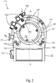
- Fig. 10 is a vacuum pump 22, for example that of the embodiment of FIG Fig. 8 , shown in cross section, the section plane being aligned perpendicular to a rotor shaft 56 and being arranged in particular at the axial height of an intermediate stage region 44.
- a first intermediate connection 46 and a second intermediate connection 48 are provided on the intermediate stage region 44. These are designed separately from one another and are spaced apart in the circumferential direction with respect to the rotor shaft 56.
- a housing wall 58 of the vacuum pump 22 extends in the circumferential direction between the intermediate connections 46 and 48.
- a deflection device 24 is effective between the housing wall 58 and the rotor shaft.
- the intermediate connections 46 and 48 are arranged opposite one another, namely in such a way that a connecting line runs eccentrically past the rotor shaft 56.
- a beam 26 is indicated by a line shown here continuously. Because due to the selected perspective, the first partial beam 30 and the second partial beam 32 are not separately visible here, but lie one above the other. However, it goes without saying that the beam alignment selected here, with the beam plane parallel to the rotor axis or to the rotor shaft 56, is exemplary.
- the common beam 26 enters the intermediate stage area 44 through the first intermediate connection and arrives in the effective area of the deflection device 24. There, the beam 26 is divided into the partial beams 30, 32, the first partial beam 30 through the second intermediate connection 48 from the intermediate stage area 44 is brought out.
- the second partial jet 32 is directed to the pump-active area of the visible turbo rotor disk 36, specifically to the area covered by the plurality of rotor blades 60.
- the direction of rotation of the rotor shaft 56 or of the turbo rotor disk 36 preferably runs here in the clockwise direction.
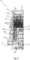
- FIG. 11 shows a vacuum pump 22 with intermediate connections 46 and 48 at an intermediate stage area 44.
- a respective intermediate connection 46 comprises a flange 62 or 64 for the tight connection of the intermediate connections 46, 48 to further components.
- the flange 62 has a flange plane 66 which extends obliquely to the rotor axis 40.
- the flange 64 also has a flange plane 68 which is oriented obliquely to the rotor axis 40.
- the intermediate connections 46 and 48 are arranged such that no straight line can be laid through the intermediate connections, that is to say that the intermediate connections are not optically transparent.
- the intermediate connections 46 and 48 are arranged in an arrow shape in this embodiment.
- possible angles of the intermediate connections and / or flange planes with respect to the rotor axis will correlate with those of the beams 26 and 30.
- the angles of the intermediate connections and / or flange planes can, however, also lie in a significantly wider angular range, since the actual deflection can possibly take place in the vicinity of the connection plane and thus a largely free choice of angle is possible.
- the vacuum pump 22 has an inlet 52. This can, for example, be connected to a chamber, for example also via a flange.
- the flange plane can, for example, run perpendicular to the rotor axis 40 or also run obliquely.
- the flange plane of the inlet 52 may also be aligned parallel to that of the flange 64 such that the pump 22 with the connections 48 and 52 can advantageously be connected to a chamber housing.
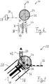
- FIG. 12 A rotor shaft 56 with rotor blades 60 of a turbo rotor disk is shown in cross section. A direction of rotation is indicated counterclockwise. Different aligned second partial beams 32 are indicated by arrows.
- the reference to second partial beams 32 is selected here and below as an example and for easier connection to the examples described above with a deflection device. It is understood that with respect to the 12 to 14 illustrated beam alignment options are generally also valid for a beam, regardless of whether it was previously separated and / or deflected.
- FIG. 12 An entry point into the pumping area is in Fig. 12 each indicated by the arrow end of the dotted arrows.
- a rotor blade 60 is shown for the purpose of illustration exactly in a rotational position corresponding to the entry points.
- the second partial beam 32.1 is guided into the pump-active area such that the partial beam 32.1 has a direction at the entry point which is directed inwards.
- the second partial beam 32.2 is oriented tangentially at the entry point with respect to the rotor shaft 56.
- the partial beam 32.3 is directed outwards at the entry point.
- the partial jet 32.1 enters the pump-active area before it passes the rotor shaft 56 or a point closest to the rotor axis.
- the partial jet 32.3 has passed the rotor shaft 56 before entering the pump-active area.
- the partial jet 32.2 enters the pumping area at the point at which it passes the rotor shaft 56.
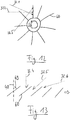
- Fig. 13 illustrates further alignment options of a beam, in particular a second partial beam, which illustrate a different perspective and in this respect independently or in combination with the alignments according to Fig. 12 are applicable.
- FIG. 13 A plurality of rotor blades 60 are shown in simplified form in a row, a direction of rotation being indicated by an arrow and extending to the right in the image plane.
- the rotor blades 60 have an angle of attack 69 with respect to the rotor axis 40.
- the second partial beams 32 can be arranged differently with respect to the rotor axis.
- the partial jet 32.4 is aligned parallel to the rotor axis and is generally steeper than the angle of attack of the rotor blades.
- the direction of the second partial jet 32.5 corresponds to the rotor blades 60, that is, it is adjusted accordingly.
- the second partial jet 32.6 is flatter than the rotor blades 46.
- a beam alignment ie a beam alignment with a direction component in the direction of rotation.
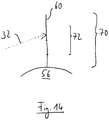
- a radial extension 70 of a rotor blade 60 is shown, which rotates in operation about the rotor axis, which in FIG Fig. 14 runs perpendicular to the image plane.
- the rotor blade 60 extends from a radially inner end, which is defined by a rotor core, a rotor shaft 56 and / or a blade base, to a radially outer end.
- the radial extension 70 forms a pump-active area of the rotor blade 60 or a turbo rotor.
- the second partial beam 32 can be guided onto a radial region 72 of the rotor blades 60, which is spaced from the radially inner end and / or from the radially outer end of the rotor blades by at least a quarter of the radial extent.
- the second partial jet 32 can be guided onto the rotor blades 60 approximately radially in the center or approximately at a third of the radial extent measured from the radially outer end.
- the beam alignment according to the invention enables a particularly high capture probability for the particles of the beam that is guided into the pump-active region, in particular the second partial beam, and in particular for those particles that do not belong to the first partial beam.
- the at least substantially complete pumping speed of the pump stage, in particular the turbo rotor disk comes into play, in the pump-active region of which the jet is guided.
- the active pumping area is advantageously arranged close to the deflection device and thus at the location at which the partial jets are separated. The conductance losses between this location and the pump-active area are therefore small.
- the invention makes it possible to remove a particularly large part of dirt particles particularly effectively and in particular to improve the accuracy of the analysis.
Landscapes
- Engineering & Computer Science (AREA)
- Mechanical Engineering (AREA)
- General Engineering & Computer Science (AREA)
- Chemical & Material Sciences (AREA)
- Analytical Chemistry (AREA)
- Non-Positive Displacement Air Blowers (AREA)
- Electron Tubes For Measurement (AREA)
- Other Investigation Or Analysis Of Materials By Electrical Means (AREA)
Priority Applications (1)
| Application Number | Priority Date | Filing Date | Title |
|---|---|---|---|
| EP20152401.4A EP3629366B1 (fr) | 2020-01-17 | 2020-01-17 | Système à vide et pompe à vide |
Applications Claiming Priority (1)
| Application Number | Priority Date | Filing Date | Title |
|---|---|---|---|
| EP20152401.4A EP3629366B1 (fr) | 2020-01-17 | 2020-01-17 | Système à vide et pompe à vide |
Publications (3)
| Publication Number | Publication Date |
|---|---|
| EP3629366A2 true EP3629366A2 (fr) | 2020-04-01 |
| EP3629366A3 EP3629366A3 (fr) | 2020-09-02 |
| EP3629366B1 EP3629366B1 (fr) | 2022-05-11 |
Family
ID=69177062
Family Applications (1)
| Application Number | Title | Priority Date | Filing Date |
|---|---|---|---|
| EP20152401.4A Active EP3629366B1 (fr) | 2020-01-17 | 2020-01-17 | Système à vide et pompe à vide |
Country Status (1)
| Country | Link |
|---|---|
| EP (1) | EP3629366B1 (fr) |
Family Cites Families (3)
| Publication number | Priority date | Publication date | Assignee | Title |
|---|---|---|---|---|
| DE10045449B4 (de) * | 2000-09-14 | 2007-03-29 | GSF - Forschungszentrum für Umwelt und Gesundheit GmbH | Verfahren und Vorrichtung zur Charakterisierung der Oberfläche gasgetragener Aerosolpartikel |
| CA2632251C (fr) * | 2005-12-22 | 2011-06-21 | Thermo Finnigan Llc | Appareil et procede de pompage dans un dispositif optique a ions |
| GB2553937B (en) * | 2015-03-06 | 2022-06-08 | Micromass Ltd | Improved ionisation of gaseous samples |
-
2020
- 2020-01-17 EP EP20152401.4A patent/EP3629366B1/fr active Active
Also Published As
| Publication number | Publication date |
|---|---|
| EP3629366B1 (fr) | 2022-05-11 |
| EP3629366A3 (fr) | 2020-09-02 |
Similar Documents
| Publication | Publication Date | Title |
|---|---|---|
| DE602004008089T2 (de) | Vakuumpumpe | |
| EP1078166A1 (fr) | Pompe a vide a friction dotee d'un stator et d'un rotor | |
| EP2295812A1 (fr) | Récipient repliable | |
| EP4108931B1 (fr) | Procédé permettant de faire fonctionner une pompe à vide moléculaire pour obtenir une puissance d'aspiration améliorée | |
| EP4108932B1 (fr) | Reciate et système avec reciate et pompe à vide élevé | |
| EP3851680B1 (fr) | Pompe à vide moléculaire et procédé d'influence de la capacité d'aspiration d'une telle pompe | |
| EP3112687B1 (fr) | Détection de la circulation d'un gaz auxiliaire qui est injecté dans une pompe à vide | |
| EP3845764A2 (fr) | Pompe à vide et système de pompe à vide | |
| EP3670924B1 (fr) | Pompe à vide et procédé de fabrication d'une telle pompe à vide | |
| EP3629366B1 (fr) | Système à vide et pompe à vide | |
| DE69302831T2 (de) | Zentrifugal-Partikelklassierer mit Verteiler zum uniformen Zufluss | |
| EP3734078B1 (fr) | Pompe turbomoléculaire et procédé de fabrication d'un disque de stator pour une telle pompe | |
| EP3135932B1 (fr) | Pompe à vide et palier à aimant permanent | |
| EP3926175A1 (fr) | Pompe à vide dotée d'un palier à roulement | |
| EP4144994B1 (fr) | Dispositif et procédé d'évaluation d'un palier magnétique | |
| EP3327293B1 (fr) | Pompe à vide avec une pluralté d'entrées | |
| EP2990656A2 (fr) | Pompe à vide | |
| EP3196471B1 (fr) | Pompe a vide | |
| EP4194700A1 (fr) | Pompe à vide avec étage de pompe de holweck à géométrie de holweck variable | |
| EP3462036B1 (fr) | Pompe à vide turbomoléculaire | |
| EP3564538B1 (fr) | Système à vide et procédé de fabrication d'un tel système à vide | |
| EP3767109B1 (fr) | Système à vide | |
| EP4273405B1 (fr) | Pompe à vide avec un étage de pompage de type holweck avec une géométrie holweck variable | |
| EP4269804B1 (fr) | Pompe à vide | |
| DE102015113821A1 (de) | Vakuumpumpe |
Legal Events
| Date | Code | Title | Description |
|---|---|---|---|
| PUAI | Public reference made under article 153(3) epc to a published international application that has entered the european phase |
Free format text: ORIGINAL CODE: 0009012 |
|
| STAA | Information on the status of an ep patent application or granted ep patent |
Free format text: STATUS: THE APPLICATION HAS BEEN PUBLISHED |
|
| AK | Designated contracting states |
Kind code of ref document: A2 Designated state(s): AL AT BE BG CH CY CZ DE DK EE ES FI FR GB GR HR HU IE IS IT LI LT LU LV MC MK MT NL NO PL PT RO RS SE SI SK SM TR |
|
| AX | Request for extension of the european patent |
Extension state: BA ME |
|
| PUAL | Search report despatched |
Free format text: ORIGINAL CODE: 0009013 |
|
| AK | Designated contracting states |
Kind code of ref document: A3 Designated state(s): AL AT BE BG CH CY CZ DE DK EE ES FI FR GB GR HR HU IE IS IT LI LT LU LV MC MK MT NL NO PL PT RO RS SE SI SK SM TR |
|
| AX | Request for extension of the european patent |
Extension state: BA ME |
|
| RIC1 | Information provided on ipc code assigned before grant |
Ipc: F04B 37/06 20060101ALI20200727BHEP Ipc: H01J 49/24 20060101AFI20200727BHEP Ipc: F04B 37/14 20060101ALI20200727BHEP Ipc: F04D 19/04 20060101ALI20200727BHEP Ipc: F04B 37/08 20060101ALI20200727BHEP |
|
| STAA | Information on the status of an ep patent application or granted ep patent |
Free format text: STATUS: REQUEST FOR EXAMINATION WAS MADE |
|
| 17P | Request for examination filed |
Effective date: 20210105 |
|
| RBV | Designated contracting states (corrected) |
Designated state(s): AL AT BE BG CH CY CZ DE DK EE ES FI FR GB GR HR HU IE IS IT LI LT LU LV MC MK MT NL NO PL PT RO RS SE SI SK SM TR |
|
| STAA | Information on the status of an ep patent application or granted ep patent |
Free format text: STATUS: EXAMINATION IS IN PROGRESS |
|
| STAA | Information on the status of an ep patent application or granted ep patent |
Free format text: STATUS: REQUEST FOR EXAMINATION WAS MADE |
|
| 17Q | First examination report despatched |
Effective date: 20210422 |
|
| STAA | Information on the status of an ep patent application or granted ep patent |
Free format text: STATUS: EXAMINATION IS IN PROGRESS |
|
| 17Q | First examination report despatched |
Effective date: 20210723 |
|
| GRAP | Despatch of communication of intention to grant a patent |
Free format text: ORIGINAL CODE: EPIDOSNIGR1 |
|
| STAA | Information on the status of an ep patent application or granted ep patent |
Free format text: STATUS: GRANT OF PATENT IS INTENDED |
|
| INTG | Intention to grant announced |
Effective date: 20220127 |
|
| GRAS | Grant fee paid |
Free format text: ORIGINAL CODE: EPIDOSNIGR3 |
|
| GRAA | (expected) grant |
Free format text: ORIGINAL CODE: 0009210 |
|
| STAA | Information on the status of an ep patent application or granted ep patent |
Free format text: STATUS: THE PATENT HAS BEEN GRANTED |
|
| AK | Designated contracting states |
Kind code of ref document: B1 Designated state(s): AL AT BE BG CH CY CZ DE DK EE ES FI FR GB GR HR HU IE IS IT LI LT LU LV MC MK MT NL NO PL PT RO RS SE SI SK SM TR |
|
| REG | Reference to a national code |
Ref country code: GB Ref legal event code: FG4D Free format text: NOT ENGLISH |
|
| REG | Reference to a national code |
Ref country code: CH Ref legal event code: EP |
|
| REG | Reference to a national code |
Ref country code: AT Ref legal event code: REF Ref document number: 1492174 Country of ref document: AT Kind code of ref document: T Effective date: 20220515 |
|
| REG | Reference to a national code |
Ref country code: DE Ref legal event code: R096 Ref document number: 502020001072 Country of ref document: DE |
|
| REG | Reference to a national code |
Ref country code: IE Ref legal event code: FG4D Free format text: LANGUAGE OF EP DOCUMENT: GERMAN |
|
| REG | Reference to a national code |
Ref country code: LT Ref legal event code: MG9D |
|
| REG | Reference to a national code |
Ref country code: NL Ref legal event code: MP Effective date: 20220511 |
|
| PG25 | Lapsed in a contracting state [announced via postgrant information from national office to epo] |
Ref country code: SE Free format text: LAPSE BECAUSE OF FAILURE TO SUBMIT A TRANSLATION OF THE DESCRIPTION OR TO PAY THE FEE WITHIN THE PRESCRIBED TIME-LIMIT Effective date: 20220511 Ref country code: PT Free format text: LAPSE BECAUSE OF FAILURE TO SUBMIT A TRANSLATION OF THE DESCRIPTION OR TO PAY THE FEE WITHIN THE PRESCRIBED TIME-LIMIT Effective date: 20220912 Ref country code: NO Free format text: LAPSE BECAUSE OF FAILURE TO SUBMIT A TRANSLATION OF THE DESCRIPTION OR TO PAY THE FEE WITHIN THE PRESCRIBED TIME-LIMIT Effective date: 20220811 Ref country code: NL Free format text: LAPSE BECAUSE OF FAILURE TO SUBMIT A TRANSLATION OF THE DESCRIPTION OR TO PAY THE FEE WITHIN THE PRESCRIBED TIME-LIMIT Effective date: 20220511 Ref country code: LT Free format text: LAPSE BECAUSE OF FAILURE TO SUBMIT A TRANSLATION OF THE DESCRIPTION OR TO PAY THE FEE WITHIN THE PRESCRIBED TIME-LIMIT Effective date: 20220511 Ref country code: HR Free format text: LAPSE BECAUSE OF FAILURE TO SUBMIT A TRANSLATION OF THE DESCRIPTION OR TO PAY THE FEE WITHIN THE PRESCRIBED TIME-LIMIT Effective date: 20220511 Ref country code: GR Free format text: LAPSE BECAUSE OF FAILURE TO SUBMIT A TRANSLATION OF THE DESCRIPTION OR TO PAY THE FEE WITHIN THE PRESCRIBED TIME-LIMIT Effective date: 20220812 Ref country code: FI Free format text: LAPSE BECAUSE OF FAILURE TO SUBMIT A TRANSLATION OF THE DESCRIPTION OR TO PAY THE FEE WITHIN THE PRESCRIBED TIME-LIMIT Effective date: 20220511 Ref country code: ES Free format text: LAPSE BECAUSE OF FAILURE TO SUBMIT A TRANSLATION OF THE DESCRIPTION OR TO PAY THE FEE WITHIN THE PRESCRIBED TIME-LIMIT Effective date: 20220511 Ref country code: BG Free format text: LAPSE BECAUSE OF FAILURE TO SUBMIT A TRANSLATION OF THE DESCRIPTION OR TO PAY THE FEE WITHIN THE PRESCRIBED TIME-LIMIT Effective date: 20220811 |
|
| PG25 | Lapsed in a contracting state [announced via postgrant information from national office to epo] |
Ref country code: RS Free format text: LAPSE BECAUSE OF FAILURE TO SUBMIT A TRANSLATION OF THE DESCRIPTION OR TO PAY THE FEE WITHIN THE PRESCRIBED TIME-LIMIT Effective date: 20220511 Ref country code: PL Free format text: LAPSE BECAUSE OF FAILURE TO SUBMIT A TRANSLATION OF THE DESCRIPTION OR TO PAY THE FEE WITHIN THE PRESCRIBED TIME-LIMIT Effective date: 20220511 Ref country code: LV Free format text: LAPSE BECAUSE OF FAILURE TO SUBMIT A TRANSLATION OF THE DESCRIPTION OR TO PAY THE FEE WITHIN THE PRESCRIBED TIME-LIMIT Effective date: 20220511 Ref country code: IS Free format text: LAPSE BECAUSE OF FAILURE TO SUBMIT A TRANSLATION OF THE DESCRIPTION OR TO PAY THE FEE WITHIN THE PRESCRIBED TIME-LIMIT Effective date: 20220911 |
|
| PG25 | Lapsed in a contracting state [announced via postgrant information from national office to epo] |
Ref country code: SM Free format text: LAPSE BECAUSE OF FAILURE TO SUBMIT A TRANSLATION OF THE DESCRIPTION OR TO PAY THE FEE WITHIN THE PRESCRIBED TIME-LIMIT Effective date: 20220511 Ref country code: SK Free format text: LAPSE BECAUSE OF FAILURE TO SUBMIT A TRANSLATION OF THE DESCRIPTION OR TO PAY THE FEE WITHIN THE PRESCRIBED TIME-LIMIT Effective date: 20220511 Ref country code: RO Free format text: LAPSE BECAUSE OF FAILURE TO SUBMIT A TRANSLATION OF THE DESCRIPTION OR TO PAY THE FEE WITHIN THE PRESCRIBED TIME-LIMIT Effective date: 20220511 Ref country code: EE Free format text: LAPSE BECAUSE OF FAILURE TO SUBMIT A TRANSLATION OF THE DESCRIPTION OR TO PAY THE FEE WITHIN THE PRESCRIBED TIME-LIMIT Effective date: 20220511 Ref country code: DK Free format text: LAPSE BECAUSE OF FAILURE TO SUBMIT A TRANSLATION OF THE DESCRIPTION OR TO PAY THE FEE WITHIN THE PRESCRIBED TIME-LIMIT Effective date: 20220511 |
|
| REG | Reference to a national code |
Ref country code: DE Ref legal event code: R097 Ref document number: 502020001072 Country of ref document: DE |
|
| PLBE | No opposition filed within time limit |
Free format text: ORIGINAL CODE: 0009261 |
|
| STAA | Information on the status of an ep patent application or granted ep patent |
Free format text: STATUS: NO OPPOSITION FILED WITHIN TIME LIMIT |
|
| PG25 | Lapsed in a contracting state [announced via postgrant information from national office to epo] |
Ref country code: AL Free format text: LAPSE BECAUSE OF FAILURE TO SUBMIT A TRANSLATION OF THE DESCRIPTION OR TO PAY THE FEE WITHIN THE PRESCRIBED TIME-LIMIT Effective date: 20220511 |
|
| 26N | No opposition filed |
Effective date: 20230214 |
|
| PG25 | Lapsed in a contracting state [announced via postgrant information from national office to epo] |
Ref country code: SI Free format text: LAPSE BECAUSE OF FAILURE TO SUBMIT A TRANSLATION OF THE DESCRIPTION OR TO PAY THE FEE WITHIN THE PRESCRIBED TIME-LIMIT Effective date: 20220511 |
|
| REG | Reference to a national code |
Ref country code: CH Ref legal event code: PL |
|
| PG25 | Lapsed in a contracting state [announced via postgrant information from national office to epo] |
Ref country code: LU Free format text: LAPSE BECAUSE OF NON-PAYMENT OF DUE FEES Effective date: 20230117 |
|
| REG | Reference to a national code |
Ref country code: BE Ref legal event code: MM Effective date: 20230131 |
|
| PG25 | Lapsed in a contracting state [announced via postgrant information from national office to epo] |
Ref country code: LI Free format text: LAPSE BECAUSE OF NON-PAYMENT OF DUE FEES Effective date: 20230131 Ref country code: CH Free format text: LAPSE BECAUSE OF NON-PAYMENT OF DUE FEES Effective date: 20230131 |
|
| PG25 | Lapsed in a contracting state [announced via postgrant information from national office to epo] |
Ref country code: FR Free format text: LAPSE BECAUSE OF NON-PAYMENT OF DUE FEES Effective date: 20230131 Ref country code: BE Free format text: LAPSE BECAUSE OF NON-PAYMENT OF DUE FEES Effective date: 20230131 |
|
| PG25 | Lapsed in a contracting state [announced via postgrant information from national office to epo] |
Ref country code: IE Free format text: LAPSE BECAUSE OF NON-PAYMENT OF DUE FEES Effective date: 20230117 |
|
| PG25 | Lapsed in a contracting state [announced via postgrant information from national office to epo] |
Ref country code: MC Free format text: LAPSE BECAUSE OF FAILURE TO SUBMIT A TRANSLATION OF THE DESCRIPTION OR TO PAY THE FEE WITHIN THE PRESCRIBED TIME-LIMIT Effective date: 20220511 |
|
| PG25 | Lapsed in a contracting state [announced via postgrant information from national office to epo] |
Ref country code: MC Free format text: LAPSE BECAUSE OF FAILURE TO SUBMIT A TRANSLATION OF THE DESCRIPTION OR TO PAY THE FEE WITHIN THE PRESCRIBED TIME-LIMIT Effective date: 20220511 |
|
| PG25 | Lapsed in a contracting state [announced via postgrant information from national office to epo] |
Ref country code: BG Free format text: LAPSE BECAUSE OF FAILURE TO SUBMIT A TRANSLATION OF THE DESCRIPTION OR TO PAY THE FEE WITHIN THE PRESCRIBED TIME-LIMIT Effective date: 20220511 |
|
| PG25 | Lapsed in a contracting state [announced via postgrant information from national office to epo] |
Ref country code: BG Free format text: LAPSE BECAUSE OF FAILURE TO SUBMIT A TRANSLATION OF THE DESCRIPTION OR TO PAY THE FEE WITHIN THE PRESCRIBED TIME-LIMIT Effective date: 20220511 |
|
| PGFP | Annual fee paid to national office [announced via postgrant information from national office to epo] |
Ref country code: AT Payment date: 20250417 Year of fee payment: 5 |
|
| PG25 | Lapsed in a contracting state [announced via postgrant information from national office to epo] |
Ref country code: CY Free format text: LAPSE BECAUSE OF FAILURE TO SUBMIT A TRANSLATION OF THE DESCRIPTION OR TO PAY THE FEE WITHIN THE PRESCRIBED TIME-LIMIT; INVALID AB INITIO Effective date: 20200117 |
|
| PG25 | Lapsed in a contracting state [announced via postgrant information from national office to epo] |
Ref country code: HU Free format text: LAPSE BECAUSE OF FAILURE TO SUBMIT A TRANSLATION OF THE DESCRIPTION OR TO PAY THE FEE WITHIN THE PRESCRIBED TIME-LIMIT; INVALID AB INITIO Effective date: 20200117 |
|
| PG25 | Lapsed in a contracting state [announced via postgrant information from national office to epo] |
Ref country code: TR Free format text: LAPSE BECAUSE OF FAILURE TO SUBMIT A TRANSLATION OF THE DESCRIPTION OR TO PAY THE FEE WITHIN THE PRESCRIBED TIME-LIMIT Effective date: 20220511 |
|
| REG | Reference to a national code |
Ref country code: AT Ref legal event code: MM01 Ref document number: 1492174 Country of ref document: AT Kind code of ref document: T Effective date: 20250117 |
|
| PGFP | Annual fee paid to national office [announced via postgrant information from national office to epo] |
Ref country code: GB Payment date: 20260123 Year of fee payment: 7 |
|
| PGFP | Annual fee paid to national office [announced via postgrant information from national office to epo] |
Ref country code: DE Payment date: 20260328 Year of fee payment: 7 |
|
| PG25 | Lapsed in a contracting state [announced via postgrant information from national office to epo] |
Ref country code: AT Free format text: LAPSE BECAUSE OF NON-PAYMENT OF DUE FEES Effective date: 20250117 |
|
| PGFP | Annual fee paid to national office [announced via postgrant information from national office to epo] |
Ref country code: IT Payment date: 20260126 Year of fee payment: 7 |
|
| PGFP | Annual fee paid to national office [announced via postgrant information from national office to epo] |
Ref country code: CZ Payment date: 20260114 Year of fee payment: 7 |