EP3631823B1 - Procédé et système d'alimentation de bande ainsi qu'installation pour la production de tôles feuilletées pour transformateurs - Google Patents
Procédé et système d'alimentation de bande ainsi qu'installation pour la production de tôles feuilletées pour transformateurs Download PDFInfo
- Publication number
- EP3631823B1 EP3631823B1 EP18731911.6A EP18731911A EP3631823B1 EP 3631823 B1 EP3631823 B1 EP 3631823B1 EP 18731911 A EP18731911 A EP 18731911A EP 3631823 B1 EP3631823 B1 EP 3631823B1
- Authority
- EP
- European Patent Office
- Prior art keywords
- feeding
- band
- βii
- guide
- input
- Prior art date
- Legal status (The legal status is an assumption and is not a legal conclusion. Google has not performed a legal analysis and makes no representation as to the accuracy of the status listed.)
- Active
Links
Images




Classifications
-
- H—ELECTRICITY
- H01—ELECTRIC ELEMENTS
- H01F—MAGNETS; INDUCTANCES; TRANSFORMERS; SELECTION OF MATERIALS FOR THEIR MAGNETIC PROPERTIES
- H01F41/00—Apparatus or processes specially adapted for manufacturing or assembling magnets, inductances or transformers; Apparatus or processes specially adapted for manufacturing materials characterised by their magnetic properties
- H01F41/02—Apparatus or processes specially adapted for manufacturing or assembling magnets, inductances or transformers; Apparatus or processes specially adapted for manufacturing materials characterised by their magnetic properties for manufacturing cores, coils, or magnets
- H01F41/0206—Manufacturing of magnetic cores by mechanical means
- H01F41/0233—Manufacturing of magnetic circuits made from sheets
-
- H—ELECTRICITY
- H01—ELECTRIC ELEMENTS
- H01F—MAGNETS; INDUCTANCES; TRANSFORMERS; SELECTION OF MATERIALS FOR THEIR MAGNETIC PROPERTIES
- H01F41/00—Apparatus or processes specially adapted for manufacturing or assembling magnets, inductances or transformers; Apparatus or processes specially adapted for manufacturing materials characterised by their magnetic properties
- H01F41/02—Apparatus or processes specially adapted for manufacturing or assembling magnets, inductances or transformers; Apparatus or processes specially adapted for manufacturing materials characterised by their magnetic properties for manufacturing cores, coils, or magnets
- H01F41/0206—Manufacturing of magnetic cores by mechanical means
-
- H—ELECTRICITY
- H01—ELECTRIC ELEMENTS
- H01F—MAGNETS; INDUCTANCES; TRANSFORMERS; SELECTION OF MATERIALS FOR THEIR MAGNETIC PROPERTIES
- H01F41/00—Apparatus or processes specially adapted for manufacturing or assembling magnets, inductances or transformers; Apparatus or processes specially adapted for manufacturing materials characterised by their magnetic properties
- H01F41/02—Apparatus or processes specially adapted for manufacturing or assembling magnets, inductances or transformers; Apparatus or processes specially adapted for manufacturing materials characterised by their magnetic properties for manufacturing cores, coils, or magnets
- H01F41/0206—Manufacturing of magnetic cores by mechanical means
- H01F41/0213—Manufacturing of magnetic circuits made from strip(s) or ribbon(s)
Definitions
- This patent application relates to a band feeding process and system for a plant for the production of laminated cores for transformers, in particular for the production of cores with stacked grain-oriented laminations for electrical energy transmission and distribution transformers, namely for transformers with a power exceeding 10kVA.
- This patent application further relates to a plant for the production of laminated cores for transformers, in particular for the production of cores with stacked grain-oriented laminations for electrical energy transmission and distribution transformers, namely for transformers with a power exceeding 10kVA.
- Laminated cores of this type are large-sized and significantly heavy, thus requiring suitable production plants and manipulation instruments.
- laminated cores of the type described above usually comprise a lower joke, an upper joke and a plurality of columns, which transversely connect the lower joke and the upper joke to one another.
- the columns of the cores can have lengths ranging, for example, from 0.5 to 5 metres.
- these cores are manufactured through the combination and overlapping of a plurality of flat laminations, which are never subjected to bending.
- Known plants have a feeding station where a spool is unwound so as to feed, through an input, a band to a processing unit, in order to cut and separate the band.
- the spool is replaced.
- known plants comprise one single multispindle reel, wherein each spindle supports a respective spool. Therefore, the band exchange in a known plant basically comprises the following steps:
- Japanese document JP56062306 discloses a feeding process for a plant for the production of cores with stacked lamination for transformers.
- the object of the invention is to provide a feeding process and system, which allow the band to be exchanged in a few seconds.
- FIG 1 O indicates, as a whole, a laminated core, in particular for distribution or power transformers, namely for electrical energy transmission and distribution transformers, namely for transformers with a power exceeding 10 kVA.
- the core O comprises, in a known manner, a lower joke GI and an upper joke GS, which are transversely connected to one another by a plurality of columns C. According to the example shown, there are three columns, two side ones indicated with C1 and C3 and a central one indicated with C2.
- Each joke GI, GS and each column are manufactured by overlapping a plurality of laminations P made of magnetic silicon steel.
- Each joke GI, GS is connected to respective ends of the columns C1, C2 and C3 by means of a shape coupling, in particular by means of a herringbone coupling.
- At least part of the core O described above was manufactured by cutting and overlapping the laminations P starting from one single band B.
- the plant 1 comprises, in a known and schematically shown manner, a processing unit 2, which has, in turn, one or more cutting stations ⁇ arranged in series, where the singles laminations P are cut and separated from one another starting from a ferromagnetic metal material band B, in particular made of magnetic silicon steel.
- the plant 1 further comprises a stacking unit 3 downstream of the processing unit 2, where stacks of laminations P are obtained (in a known manner) in order to form the jokes GI, GS and the columns C1, C2 and C3.
- the plant 1 further comprises a feeding system 4, which is configured, as explained more in detail below, to feed a band B selected among a plurality of different bands, in particular having different widths, to the processing unit 2 in a basically instantaneous manner.
- This feeding system 4 find advantageous application especially when the band B in the processing unit 2 needs to be replaced.
- the processing unit 2 has an interface input I interfaced with the feeding system 4, thus allowing bands B coming from the feeding system 4 to get into the processing station 2.
- the feeding system 4 has a plurality of feeding stations ⁇ , each configured to feed a respective band B to the input I.
- upstream and downstream are used with reference to the feeding direction of a band B from the respective feeding station ⁇ towards the input I.
- the feeding system 4 is configured to selectively feed a plurality of continuous bands B1-B8, which are wound in spools 5 and are made of a ferromagnetic material, namely a material that is suited to be used to manufacture laminations P of a transformer core K.
- the feeding system 4 is configured to feed, starting from respective spools 5, bands B1-B8 made of magnetic silicon steel.
- the feeding system 4 comprises a known and schematically shown reel 6 for each feeding station ⁇ .
- each reel 6 is configured to support, unwind and rewind in a known manner a respective spool 5.
- each reel 6 comprises a spindle 7, which is rotary and is configured to unwind and rewind, in a known manner, a respective spool 5.
- the feeding system 4 has tow feeding stations, hereinafter indicated with ⁇ I and ⁇ II.
- the feeding stations ⁇ I and ⁇ II are connected in parallel to the input I, as described more in detail below.
- the feeding system 4 comprises a reel 61 and 611 for each feeding station ⁇ I and ⁇ II, respectively.
- Each reel 6I, 6II comprises, in turn, a plurality of spindles 7.
- each reel 6I, 6II comprises four spindles 71-74 and 75-78.
- Each reel 6I, 6II is rotary around a vertical axis AI, AII and is configured to place, in a known manner, and in the area of the respective feeding station ⁇ I, ⁇ II, a band B selected among its group of bands B1-B4 and B5-B8, respectively, which are installed and available.
- the feeding system 4 comprises an exchange unit 8, which is arranged upstream of the input I.
- the exchange unit 8 interposed between each feeding station ⁇ and the input I.
- the plant 1 comprises a plurality of guides 9, each of which is configured to guide the band B from a respective feeding station ⁇ to the exchange unit 8.
- the feeding system 4 comprises two guides, hereinafter indicated with 9I and 9II.
- the guides 9I and 9II have longitudinal axes X, which are parallel to one another.
- the guides 91 and 911 overlap one another so that each band B is aligned with a predetermined machine axis XII of the processing unit 2.
- the exchange unit 8 is configured to connect, in use, to the input I a guide 9 selected in the group of guides 9I and 9II.
- the exchange unit 8 is interposed between each feeding station ⁇ and the input I. According to the embodiment shown in figures from 7 to 11, the exchange unit 8 is under the guides 9.
- the feeding system 4 can comprise a different number of feeding stations ⁇ and, accordingly, of reels 6 and guides 9.
- the feeding system 4 can comprise: three or more feeding stations ⁇ ; three or more guides 9; three or more reels 6.
- the exchange unit 8 comprises a switch 10, which is configured to connect to the input I a guide 9 selected between the guides 91 and 911.
- the switch 10 is an oscillating body, which, depending on its position relative to a rotation axis of its, connects a respective guide 9 to the input I.
- the switch 10 is a translating body, which can be selectively arranged in a plurality of different positions, each permitting the connection of a respective guide 9 to the input I.
- the exchange unit 8 at least partly translates the guides 9, in particular at least the end portion of the guides 9, so as to align them with the input I.
- the guides 9 are hinged in correspondence of a free end opposite to the exchange unit 8.
- the guides 9 are at least partially overlapped, in particular the guide 91 lays on an end portion of the guide 911.
- the guide 911 is hinged in the area of a free end 100 opposite to the exchange unit 8 to rotate around a rotation axis Y.
- the rotation axis Y is parallel to the support plane and is perpendicular to the longitudinal axis X of the guide 911.
- the exchange unit 8 comprises a switch 110, which is configured to move the guides 9I and 9II transversally, in particular perpendicularly, to the support plane so as to rotate the guides 91 and 911 around the rotation axis Y.
- the switch 110 comprises a cylinder 111 connected to the guide 911 and interposed between the guide 9II and the support plane.
- the guides 9I and 9II face directly the input I.
- the exchange unit 8 is disposed beneath the guides 9. In this way, the feeding system 4 is compact.
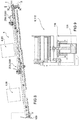
- Figure 10 shows the guide 91 in connection with the input and figure 11 shows the guide 911 in connection with the input I.
- the feeding system 4 can comprise mutando mutandis a more guides 9 and respective reels 6.
- the feeding system 4 further has a waiting station ⁇ , which is arranged upstream of the exchange unit 8.
- the waiting station ⁇ corresponds at the end portions of the guides 9I and 9II facing the input I
- the plant 1 further comprises a control system 11, which is configured to exchange data with the processing unit 2, each reel 6, each spindle 7 of the reels 6 and the exchange unit 8.
- the control system 11 is configured to rotate each reel 6 based on the type of processing to be carried out.
- control system 11 is configured to exchange data with and adjust the operation of each spindle 7, based on the type of processing to be carried out.
- control system 11 is configured to adjust the operation of the switch 10 or 110 of the exchange unit 8, based on the type of processing to be carried out.
- control system 11 comprises a user interface 12, through which the control system 11 exchanges data with an operator.
- the user interface 12 comprises a display or a mobile device and/or a remote unit, for example a pc or a tablet.
- the feeding system 4 comprises a Cartesian manipulator 200I, 200II for each guide 9I and 9II, respectively.
- the Cartesian manipulators 200I and 200II are substantially equal to each other and in the following only a generic manipulator 200 will be described for conciseness.
- Each manipulator 200 comprises a guide 201, which is substantially parallel to the respective guide 9, and a gripping head 202 which is mounted so as to slide along said guide 201 from a parking position ⁇ to a working position ⁇ and viceversa.
- the gripping head 202 comprises a gripper 203 and is configured to to grip a portion of a band B and introduce it in the processing line.
- the gripping head 202 is configured to introduce the end portion of a band B between the respective guide 9 and some motorized wheels, which are configured to push the band B along the respective guide 9 towards the waiting station ⁇ .
- the gripper 203 can be electromagnetic, can comprise pneumatic gripping systems and/o suckers and/or other equivalents elements, for example interlocking elements or interfering elements.
- the band B1 is coupled, in a known manner which is not shown herein, to the respective guide 9I. Then, in a known manner which is not shown herein, initialization operations are carried out based on the width of the band B1, namely operations to align the band B1 itself with the machine axis of the cutting unit 2.
- the band B1 is fed, in a known and schematically shown manner, to the processing unit 2 through the waiting station ⁇ , the exchange unit 8 and the input I.
- the feeding system 4 carries out an initialization operation on another, still free guide 9, so as to prepare a replacing band B.
- the initial flap of the replacing band B is brought up to the waiting station ⁇ , where the feeding of the replacing band B is interrupted.
- the feeding system 4 carries out the initialization operation of the replacing band B5 on the guide 911.
- the initial flap of the replacing band B2 is brought up to the waiting station ⁇ .
- the feeding of the replacing band B5 is interrupted when it reaches the waiting station ⁇ .
- the band B inside the processing unit 2 is forced to go back. In particular, it is rewound around its spool 5.
- the switch 10 of the exchange unit is operated so as to allow the replacing band B to be fed through the input I of the processing unit 2.
- the replacing band B is fed in a known manner, until the following exchange of the band B is requested.
- the band B1 when the band is exchanged, the band B1 is forced to go back, namely is rewound around its own spool 5, until the initial flap of the of the band B1 is interposed between the respective spindle 71 and the waiting station ⁇ .
- the switch 10 or 110 is operated so as to connect the guide 911 to the input I ( figure 6 ).
- the band B5 is fed so as to go through the input I and reach, in a known manner, the processing unit 2.
- the band B when the band B is caused to go back, it can be completely rewound around its own spool 5, so as to permit the rotation of the respective reel 6 and the positioning of a further band B in the area of the respective feeding station ⁇ . In this way, the replacement of the band B fed to the processing unit 2 is obtained. Furthermore, the initialization operations of the further band B can be carried out in masked time, as explained above.
- the initialization operations of the further band B can be realized automatically by means of the each manipulator 200.
- a band B when a band B is forced to go back, it can be left lying on the respective guide 9 with its initial flap arranged close to the waiting station ⁇ . By so doing, the band B is already available, without having to carry out the initialization operations again in case it has to be used immediately after the processing of the replacing band B.
- the feeding process, the feeding system 4 and the plant 1 described above allow the band B being processed in the processing unit 2 to be replaced in extremely reduced times (a few seconds) compared to the amounts of time currently needed in known plants.
- the feeding process, the feeding system 4 and the plant 1 described above allow the initialization operations to be performed on a band B to be fed to the processing unit 2 to be carried out in masked time.
- the initialization of band B takes place while the plant 1 is working, hence the plant 1 does not need to be stopped any longer for the replacement of the band B.
- the feeding process, the feeding system 4 and the plant 1 described above can work in an automatic and continuous manner, the presence of the operators being necessary only for the installation of the spools 5 on the respective spindles 7 and/or to couple the initial flap of a band B to a respective guide 9.
Landscapes
- Engineering & Computer Science (AREA)
- Power Engineering (AREA)
- Manufacturing & Machinery (AREA)
- Manufacturing Cores, Coils, And Magnets (AREA)
- Basic Packing Technique (AREA)
- Replacement Of Web Rolls (AREA)
- Sheets, Magazines, And Separation Thereof (AREA)
Claims (15)
- Procédé d'alimentation d'une installation (1) pour la production de noyaux (O) avec des lamelles empilées, en particulier à grains orientés, pour des transformateurs ; l'installation (1) comprenant une unité de traitement (2) et le procédé comprenant l'étape pour couper, au moyen de ladite unité de traitement (2), une bande (B ; B1 ; B5) réalisée à partir d'un matériau métallique ferromagnétique, en particulier réalisée à partir d'acier magnétique à la silice, afin d'obtenir une ou plusieurs lamelles (P) ; ladite unité de traitement (2) ayant une entrée (I) ; l'installation (1) comprenant un système d'alimentation (4) qui a une pluralité de stations d'alimentation (β ; βI ; βII), chacune configurée pour amener une bande (B ; B1 ; B5) respective à ladite entrée (I) ; le procédé étant caractérisé par l'étape pour amener à ladite entrée (I), une bande (B ; B1 ; B5) provenant d'une station d'alimentation (β ; βI ; βII) choisie parmi ladite pluralité de stations d'alimentation (β ; βI ; βII).
- Procédé selon la revendication 1, dans lequel le système d'alimentation (4) a une station d'attente (y) qui est intercalée entre chaque station d'alimentation (β ; βI ; βII) et ladite entrée (I) ; dans lequel, alors qu'une première bande (B1) est amenée par une première station d'alimentation (βI) respective à l'entrée (I), une seconde bande (B5) est amenée par une seconde station d'alimentation (βII) respective à la station d'attente (γ).
- Procédé selon l'une des revendications précédentes, dans lequel le système d'alimentation (4) comprend une pluralité de guides (9 ; 9I, 9II), dont chacun raccorde une station d'alimentation (β ; βI ; βII) respective à une station d'attente (γ) ; dans lequel lesdits guides (9 ; 9I ; 9II) sont montés en rotation autour d'un axe de rotation (Y) ; dans lequel le système d'alimentation (4) comprend une unité d'échange (8) qui est configurée pour faire tourner lesdits guides (9 ; 9I, 9II) autour de l'axe de rotation (Y) afin de raccorder à ladite entrée (I), un guide (9 ; 9I ; 9II) choisi parmi lesdits guides (9 ; 9I, 9II).
- Procédé selon la revendication 1 ou 2, dans lequel le système d'alimentation (4) comprend une pluralité de guides (9 ; 9I, 9II), dont chacun raccorde une station d'alimentation (β ; βI ; βII) respective à une station d'attente (γ) ; dans lequel le système d'alimentation (4) comprend une unité d'échange (8) qui est intercalée entre lesdits guides (9 ; 9I, 9II) et ladite entrée (I) ; dans lequel ladite unité d'échange (8) est configurée pour raccorder à ladite entrée (I), un guide (9 ; 9I ; 9II) choisi parmi lesdits guides (9 ; 9I, 9II).
- Procédé selon l'une des revendications précédentes, dans lequel le système d'alimentation (4) comprend une unité d'échange (8) ; l'unité d'échange (8) étant configurée pour transporter, sélectivement, à l'usage, chaque bande (B ; B1-B4 ; B5-B8) provenant de chaque station d'alimentation (β ; βI ; βII) vers l'entrée (I) ; dans lequel le procédé comprend une étape de changement de bande impliquant la bande (B ; B1-B4 ; B5-B8), pendant laquelle l'unité d'échange (8) est actionnée afin de permettre à une bande (B ; B1-B4 ; B5-B8) choisie parmi les bandes (B ; B1, B5) alimentées par lesdites stations d'alimentation (β ; βI ; βII) de passer vers l'entrée (I).
- Procédé selon la revendication 5, dans lequel le système d'alimentation (4) a une première et une seconde station d'alimentation (β ; βI ; βII) ; la première et la seconde station d'alimentation (β ; βI ; βII) étant configurées pour alimenter une première et respectivement une seconde bande (B ; B1, B5) ; l'installation (1) comprend un premier et un second guide (9 ; 9I, 9II) ; ledit premier guide (9 ; 9I) étant configuré pour guider une bande (B ; B1-B4) respective de la première station d'alimentation (β ; βI) à l'unité d'échange (8) ; ledit second guide (9 ; 9II) étant configuré pour guider une bande (B ; B5-B8) respective de la seconde station d'alimentation (β ; βII) à l'unité d'échange (8) ; l'unité d'échange (8) étant configurée pour raccorder, au choix, le premier guide (9 ; 9I) ou le second guide (9 ; 9II) à ladite entrée (I) ; le système d'alimentation (4) ayant une station d'attente (γ) pour chaque guide (9 ; 9I ; 9II) ; le procédé comprenant :une première étape pour amener la première bande (B ; B1) provenant de la première station d'alimentation (β ; βI) à la station de traitement (2) par ladite entrée (I) ;une deuxième étape pour amener la seconde bande (B ; B5-B8) provenant de la seconde station d'alimentation (β ; βII) à une station d'attente (γ) respective, dans lequel ladite deuxième étape d'alimentation a lieu en temps masque, c'est-à-dire alors que la première étape d'alimentation est réalisée.
- Procédé selon la revendication 6, dans lequel, dans le cas du changement de la bande (B ; B1-B4 ; B5-B8), les étapes suivantes sont réalisées séquentiellement :une troisième étape de rappel pour rappeler la première bande (B ; B1-B4) hors de l'entrée (I) ;une quatrième étape d'échange, pendant laquelle l'unité d'échange (8) est actionnée afin de raccorder ledit second guide (9 ; 9II) à l'entrée (I) ;une cinquième étape pour amener la seconde bande (B ; B5-B8) provenant de la seconde station d'alimentation (β ; βII) à l'entrée (I).
- Procédé selon l'une des revendications précédentes, dans lequel le système d'alimentation (4) comprend, dans la zone de chaque station d'alimentation (β ; βI ; βII), un dévidoir (6 ; 6I ; 6II) comprenant à son tour, une pluralité de mandrins (7 ; 71-74 ; 75-78), sur chacun desquels une bobine (5) respective de la bande (B ; B1-B8) peut être installée ; dans lequel chaque bande (B ; B1-B8) est alimentée ou rappelée, en déroulant ou en enroulant la bobine (5) respective.
- Procédé selon la revendication 8, dans lequel le type de la bande (B ; B1-B4 ; B5-B8) alimentée par une station d'alimentation (β ; βI ; βII) respective peut être remplacé en faisant tourner ledit dévidoir (6 ; 6I, 6II) afin de changer la bobine (5) présente dans la zone de la station d'alimentation (β ; βI ; βII).
- Procédé selon l'une des revendications 3, 4, 6 ou 7, dans lequel une bande (B ; B1-B4 ; B5-B8) est déroulée à partir d'une bobine (5) respective et automatiquement insérée le long d'un guide (9 ; 9I, 9II) respectif.
- Système d'alimentation (4) pour alimenter une bande (B ; B1-B4, B5-B8) pour la production de noyaux (O) avec des lamelles empilées, en particulier à grains orientés, pour transformateurs ayant une pluralité de stations d'alimentation (β ; βI ; βII) et comprenant une unité d'échange (8) ; dans lequel lesdites stations d'alimentation (β ; βI ; βII) sont raccordées en parallèle à l'unité d'change (8) ; dans lequel l'unité d'échange (8) est configurée pour amener, à l'usage, une bande (B ; B1-B4, B5-B8) choisie parmi les bandes (B ; B1-B4 ; B5-B8) alimentées par ladite pluralité de stations d'alimentation (β ; βI ; βII) à une entrée (I) d'une unité de traitement (2) d'une installation (1) pour la production de noyaux lamellaires empilés (O) ; le système d'alimentation (4) comprenant une pluralité de guides (9 ; 9I, 9II), chacun configuré pour transporter une bande (B ; B1-B4, B5-B8) d'une station d'alimentation (β ; βI ; βII) respective à l'unité d'échange (8) ; dans lequel l'unité d'échange (8) est configurée pour raccorder, à l'usage, un guide (9 ; 9I, 9II) choisi dans ledit groupe de guides (9 ; 9I, 9II) à l'entrée (I).
- Système selon la revendication 11, comprenant en outre un dévidoir (6 ; 6I ; 6II) pour chaque station d'alimentation (β ; βI ; βII) ; chaque dévidoir (6 ; 6I ; 6II) est configuré pour amener une bande (B ; B1-B4 ; B5-B8) respective dans la zone d'une station d'alimentation (β ; βI ; βII) respective ; dans lequel chaque dévidoir (6 ; 6I ; 6II) comprend une pluralité de mandrins (7 ; 71-74 ; 75-78) ; une bobine (5) respective de bande (B ; B1-B4 ; B5-B8) peut être installée, à l'usage, sur chaque mandrin (7 ; 71-74 ; 75-78).
- Système selon la revendication 11 ou 12, dans lequel lesdits guides (9 ; 9I, 9II) sont montés en rotation autour d'un axe de rotation (Y) ; ladite unité d'échange (8) étant configurée pour faire tourner lesdits guides (9 ; 9I, 9II) autour de l'axe de rotation (Y) afin de raccorder à ladite entrée (I), un guide (9 ; 9I ; 9II) choisi parmi lesdits guides (9 ; 9I, 9II).
- Système selon la revendication 11 ou 12, dans lequel le système d'alimentation (4) a une première et une seconde station d'alimentation (β ; βI ; βII) et ladite unité d'échange (8) étant intercalée, à l'usage, entre ladite entrée (I) et lesdites première et seconde stations d'alimentation (β ; βI ; βII) ; le système d'alimentation (4) comprenant un premier et un second guide (9 ; 9I, 9II) ; ledit premier guide (9 ; 9I) étant configuré pour guider une bande (B ; B1-B4) de la première station d'alimentation (β ; βI) à l'unité d'échange (8) ; ledit second guide (9 ; 9II) étant configuré pour guider une bande (B ; B5-B8) de la seconde station d'alimentation (β ; βII) à l'unité d'échange (8) ; l'unité d'échange (8) étant configurée pour raccorder sélectivement le premier guide (9 ; 9I) ou le second guide (9 ; 9II) à l'entrée (I).
- Installation pour la production de noyaux (O) avec des lamelles empilées à grains orientés pour transformateurs ; l'installation (1) comprenant une unité de traitement (2) qui est configurée pour couper une bande (B ; B1 ; B5) réalisée à partir d'un matériau métallique ferromagnétique, en particulier réalisée à partir d'un acier magnétique à la silice, afin d'obtenir une ou plusieurs lamelles (P) ; ladite unité de traitement (2) ayant une entrée (I) ; l'installation (1) comprenant un système d'alimentation (4) selon l'une des revendications 11 à 14.
Applications Claiming Priority (2)
| Application Number | Priority Date | Filing Date | Title |
|---|---|---|---|
| IT102017000059495A IT201700059495A1 (it) | 2017-05-31 | 2017-05-31 | Processo, sistema di alimentazione nastro e impianto per la produzione di nuclei lamellari per trasformatori |
| PCT/IB2018/053909 WO2018220585A1 (fr) | 2017-05-31 | 2018-05-31 | Procédé et système d'alimentation de bande ainsi qu'installation pour la production de tôles feuilletées pour transformateurs |
Publications (2)
| Publication Number | Publication Date |
|---|---|
| EP3631823A1 EP3631823A1 (fr) | 2020-04-08 |
| EP3631823B1 true EP3631823B1 (fr) | 2021-06-30 |
Family
ID=60081174
Family Applications (1)
| Application Number | Title | Priority Date | Filing Date |
|---|---|---|---|
| EP18731911.6A Active EP3631823B1 (fr) | 2017-05-31 | 2018-05-31 | Procédé et système d'alimentation de bande ainsi qu'installation pour la production de tôles feuilletées pour transformateurs |
Country Status (11)
| Country | Link |
|---|---|
| US (1) | US11114236B2 (fr) |
| EP (1) | EP3631823B1 (fr) |
| KR (1) | KR102461316B1 (fr) |
| CN (2) | CN208938799U (fr) |
| CA (1) | CA3065002A1 (fr) |
| ES (1) | ES2890276T3 (fr) |
| IT (1) | IT201700059495A1 (fr) |
| MA (1) | MA48775A (fr) |
| RU (1) | RU2764295C2 (fr) |
| SA (1) | SA519410689B1 (fr) |
| WO (1) | WO2018220585A1 (fr) |
Families Citing this family (4)
| Publication number | Priority date | Publication date | Assignee | Title |
|---|---|---|---|---|
| IT201700059495A1 (it) * | 2017-05-31 | 2018-12-01 | L A E Lughese Attrezzature Per L Elettromeccanica S R L | Processo, sistema di alimentazione nastro e impianto per la produzione di nuclei lamellari per trasformatori |
| CN110880409B (zh) * | 2019-12-10 | 2024-06-18 | 中节能西安启源机电装备有限公司 | 变压器铁心硅钢片在线剪叠一体自动生产线、方法及装置 |
| IT202000003880A1 (it) | 2020-02-25 | 2021-08-25 | L A E Lughese Attrezzature Per Lelettromeccanica S R L | Metodo per la composizione di nuclei lamellari, sistema di presa per pacchi lamellari ed impianto di produzione nuclei lamellari |
| IT202100018821A1 (it) | 2021-07-15 | 2023-01-15 | Ytd S R L | Svolgitore automatico di materiali flessibili avvolti su bobine e procedimento per alimentare una macchina operatrice con detti materiali flessibili |
Family Cites Families (16)
| Publication number | Priority date | Publication date | Assignee | Title |
|---|---|---|---|---|
| JPS5662306A (en) * | 1979-10-29 | 1981-05-28 | Toshiba Corp | Manufacturing of laminated steel core and the device |
| US4413406A (en) * | 1981-03-19 | 1983-11-08 | General Electric Company | Processing amorphous metal into packets by bonding with low melting point material |
| JPS5918624A (ja) * | 1982-07-22 | 1984-01-31 | Mitsubishi Electric Corp | 鉄心製造装置 |
| US5050294A (en) * | 1990-04-06 | 1991-09-24 | General Electric Company | Method for making a transformer core comprising amorphous steel strips surrounding the core window |
| DE4100210C2 (de) * | 1990-04-06 | 1993-10-28 | Gen Electric | Verfahren zum Herstellen eines Transformatorwickels |
| JP2975142B2 (ja) * | 1991-03-29 | 1999-11-10 | 株式会社日立製作所 | アモルファス鉄心製造方法及びその装置 |
| ITGE940022A1 (it) * | 1994-03-08 | 1995-09-08 | Tranceria Ligure S R L | Metodo rapido,economico e senza sfrido di preparazione di nuclei di trasformatori. |
| JP3850232B2 (ja) * | 2001-06-13 | 2006-11-29 | 株式会社山田ドビー | 積層コアの加工方法と装置 |
| DE102006017762B4 (de) * | 2006-04-12 | 2010-07-08 | Siemens Ag | Verfahren zum Laminieren eines Elektrobandes für Transformatorenkerne |
| CN101312090A (zh) * | 2007-05-22 | 2008-11-26 | 齐会南 | 变压器开口卷铁芯制造设备 |
| JP5867982B2 (ja) * | 2008-06-13 | 2016-02-24 | 株式会社日立産機システム | 変圧器、変圧器鉄心の製造装置及び製造方法 |
| RU2468489C2 (ru) * | 2008-10-08 | 2012-11-27 | Анатолий Сергеевич Поляков | Способ изготовления магнитопровода электромагнита броневого типа вибрационного насоса |
| JP5518639B2 (ja) * | 2010-08-31 | 2014-06-11 | 株式会社日立産機システム | 変圧器鉄心の製造装置および製造方法 |
| RU2496212C2 (ru) * | 2011-11-29 | 2013-10-20 | федеральное государственное бюджетное образовательное учреждение высшего профессионального образования "Национальный исследовательский университет "МЭИ" (ФГБОУ ВПО "НИУ МЭИ") | Способ изготовления сердечника электрической машины |
| CA2905015C (fr) * | 2013-03-13 | 2019-08-06 | Lakeview Metals, Inc. | Procede et appareil permettant de fabriquer des curs de transformateur en metal amorphe |
| IT201700059495A1 (it) * | 2017-05-31 | 2018-12-01 | L A E Lughese Attrezzature Per L Elettromeccanica S R L | Processo, sistema di alimentazione nastro e impianto per la produzione di nuclei lamellari per trasformatori |
-
2017
- 2017-05-31 IT IT102017000059495A patent/IT201700059495A1/it unknown
-
2018
- 2018-05-31 WO PCT/IB2018/053909 patent/WO2018220585A1/fr not_active Ceased
- 2018-05-31 MA MA048775A patent/MA48775A/fr unknown
- 2018-05-31 CA CA3065002A patent/CA3065002A1/fr active Pending
- 2018-05-31 KR KR1020197036899A patent/KR102461316B1/ko active Active
- 2018-05-31 ES ES18731911T patent/ES2890276T3/es active Active
- 2018-05-31 RU RU2019140764A patent/RU2764295C2/ru active
- 2018-05-31 CN CN201820841298.2U patent/CN208938799U/zh active Active
- 2018-05-31 CN CN201810552286.2A patent/CN108987084B/zh active Active
- 2018-05-31 EP EP18731911.6A patent/EP3631823B1/fr active Active
- 2018-05-31 US US16/617,336 patent/US11114236B2/en active Active
-
2019
- 2019-11-28 SA SA519410689A patent/SA519410689B1/ar unknown
Also Published As
| Publication number | Publication date |
|---|---|
| CN208938799U (zh) | 2019-06-04 |
| IT201700059495A1 (it) | 2018-12-01 |
| US20200350118A1 (en) | 2020-11-05 |
| CA3065002A1 (fr) | 2018-12-06 |
| US11114236B2 (en) | 2021-09-07 |
| KR102461316B1 (ko) | 2022-11-01 |
| KR20200028336A (ko) | 2020-03-16 |
| CN108987084A (zh) | 2018-12-11 |
| CN108987084B (zh) | 2022-04-19 |
| ES2890276T3 (es) | 2022-01-18 |
| RU2019140764A3 (fr) | 2021-11-22 |
| RU2019140764A (ru) | 2021-06-10 |
| SA519410689B1 (ar) | 2022-10-23 |
| MA48775A (fr) | 2020-04-08 |
| RU2764295C2 (ru) | 2022-01-17 |
| WO2018220585A1 (fr) | 2018-12-06 |
| EP3631823A1 (fr) | 2020-04-08 |
Similar Documents
| Publication | Publication Date | Title |
|---|---|---|
| EP3631823B1 (fr) | Procédé et système d'alimentation de bande ainsi qu'installation pour la production de tôles feuilletées pour transformateurs | |
| EP2041010B1 (fr) | Système automatisé pour produire et gérer des rouleaux de matériau en bande et robot particulièrement destiné audit système | |
| US5261152A (en) | Method for manufacturing amorphous magnetic core | |
| KR101826706B1 (ko) | 변압기 코어용 강판 가공장치 및 가공방법 | |
| JP4997074B2 (ja) | 連結コイルの形成方法および連結コイル形成装置 | |
| CN110451345B (zh) | 用于将光纤连接到卷筒的设备 | |
| CN213025819U (zh) | 一种全自动电力变压器高压绕线机辅助装置 | |
| WO2014165099A2 (fr) | Procédé et appareil permettant de fabriquer des cœurs de transformateur en métal amorphe | |
| EP1423325A1 (fr) | Systeme d'enroulement pour marchandise au metre se presentant sous forme de fil ou de bande | |
| CN220577590U (zh) | 一种光伏接线盒自动上料绕线扎带设备 | |
| CN207883852U (zh) | 电池制造控制系统及电池制造设备 | |
| WO2023187726A1 (fr) | Machine d'enroulement ayant une bobine positionnable | |
| US8276266B2 (en) | Semi-automatic system for the manufacture of electrical induction coils | |
| CN201966037U (zh) | 宽窄硅钢片复合环型铁芯 | |
| CN218057734U (zh) | 一种带有简易纸带换卷装置的纸机 | |
| WO2003105166A1 (fr) | Machine d'enroulement de cable sur un noyau toroidal | |
| GB2382340A (en) | Transporting a product | |
| JPH10163052A (ja) | 鉄心材料の搬送方法及びその搬送装置 | |
| CN211828467U (zh) | 一种用于自动穿套绕线设备的引线装置 | |
| CN218213552U (zh) | 一种用于生产铠装光缆的铠装带系统 | |
| JPH1167566A (ja) | 巻鉄心製造装置 | |
| JPH09237727A (ja) | アモルファス鉄心製造方法及びその装置 | |
| CN112919186A (zh) | 一种光缆铠装带分切系统及分切方法 | |
| CN120977773A (zh) | 一种网络变压器抽头自动扭转方法及设备 | |
| IT202300004050A1 (it) | Metodo e apparato per realizzare un cambio di bobina di nastro di elettrodo per la produzione di celle elettrochimiche |
Legal Events
| Date | Code | Title | Description |
|---|---|---|---|
| STAA | Information on the status of an ep patent application or granted ep patent |
Free format text: STATUS: UNKNOWN |
|
| STAA | Information on the status of an ep patent application or granted ep patent |
Free format text: STATUS: THE INTERNATIONAL PUBLICATION HAS BEEN MADE |
|
| PUAI | Public reference made under article 153(3) epc to a published international application that has entered the european phase |
Free format text: ORIGINAL CODE: 0009012 |
|
| STAA | Information on the status of an ep patent application or granted ep patent |
Free format text: STATUS: REQUEST FOR EXAMINATION WAS MADE |
|
| 17P | Request for examination filed |
Effective date: 20191125 |
|
| AK | Designated contracting states |
Kind code of ref document: A1 Designated state(s): AL AT BE BG CH CY CZ DE DK EE ES FI FR GB GR HR HU IE IS IT LI LT LU LV MC MK MT NL NO PL PT RO RS SE SI SK SM TR |
|
| AX | Request for extension of the european patent |
Extension state: BA ME |
|
| GRAP | Despatch of communication of intention to grant a patent |
Free format text: ORIGINAL CODE: EPIDOSNIGR1 |
|
| STAA | Information on the status of an ep patent application or granted ep patent |
Free format text: STATUS: GRANT OF PATENT IS INTENDED |
|
| INTG | Intention to grant announced |
Effective date: 20210120 |
|
| GRAS | Grant fee paid |
Free format text: ORIGINAL CODE: EPIDOSNIGR3 |
|
| GRAA | (expected) grant |
Free format text: ORIGINAL CODE: 0009210 |
|
| STAA | Information on the status of an ep patent application or granted ep patent |
Free format text: STATUS: THE PATENT HAS BEEN GRANTED |
|
| AK | Designated contracting states |
Kind code of ref document: B1 Designated state(s): AL AT BE BG CH CY CZ DE DK EE ES FI FR GB GR HR HU IE IS IT LI LT LU LV MC MK MT NL NO PL PT RO RS SE SI SK SM TR |
|
| REG | Reference to a national code |
Ref country code: CH Ref legal event code: EP |
|
| REG | Reference to a national code |
Ref country code: AT Ref legal event code: REF Ref document number: 1407117 Country of ref document: AT Kind code of ref document: T Effective date: 20210715 |
|
| REG | Reference to a national code |
Ref country code: DE Ref legal event code: R096 Ref document number: 602018019401 Country of ref document: DE |
|
| REG | Reference to a national code |
Ref country code: IE Ref legal event code: FG4D |
|
| REG | Reference to a national code |
Ref country code: LT Ref legal event code: MG9D |
|
| PG25 | Lapsed in a contracting state [announced via postgrant information from national office to epo] |
Ref country code: FI Free format text: LAPSE BECAUSE OF FAILURE TO SUBMIT A TRANSLATION OF THE DESCRIPTION OR TO PAY THE FEE WITHIN THE PRESCRIBED TIME-LIMIT Effective date: 20210630 Ref country code: HR Free format text: LAPSE BECAUSE OF FAILURE TO SUBMIT A TRANSLATION OF THE DESCRIPTION OR TO PAY THE FEE WITHIN THE PRESCRIBED TIME-LIMIT Effective date: 20210630 Ref country code: BG Free format text: LAPSE BECAUSE OF FAILURE TO SUBMIT A TRANSLATION OF THE DESCRIPTION OR TO PAY THE FEE WITHIN THE PRESCRIBED TIME-LIMIT Effective date: 20210930 |
|
| REG | Reference to a national code |
Ref country code: NL Ref legal event code: MP Effective date: 20210630 |
|
| REG | Reference to a national code |
Ref country code: AT Ref legal event code: MK05 Ref document number: 1407117 Country of ref document: AT Kind code of ref document: T Effective date: 20210630 |
|
| REG | Reference to a national code |
Ref country code: SK Ref legal event code: T3 Ref document number: E 38221 Country of ref document: SK |
|
| REG | Reference to a national code |
Ref country code: NO Ref legal event code: T2 Effective date: 20210630 |
|
| PG25 | Lapsed in a contracting state [announced via postgrant information from national office to epo] |
Ref country code: GR Free format text: LAPSE BECAUSE OF FAILURE TO SUBMIT A TRANSLATION OF THE DESCRIPTION OR TO PAY THE FEE WITHIN THE PRESCRIBED TIME-LIMIT Effective date: 20211001 Ref country code: RS Free format text: LAPSE BECAUSE OF FAILURE TO SUBMIT A TRANSLATION OF THE DESCRIPTION OR TO PAY THE FEE WITHIN THE PRESCRIBED TIME-LIMIT Effective date: 20210630 Ref country code: SE Free format text: LAPSE BECAUSE OF FAILURE TO SUBMIT A TRANSLATION OF THE DESCRIPTION OR TO PAY THE FEE WITHIN THE PRESCRIBED TIME-LIMIT Effective date: 20210630 Ref country code: LV Free format text: LAPSE BECAUSE OF FAILURE TO SUBMIT A TRANSLATION OF THE DESCRIPTION OR TO PAY THE FEE WITHIN THE PRESCRIBED TIME-LIMIT Effective date: 20210630 |
|
| REG | Reference to a national code |
Ref country code: ES Ref legal event code: FG2A Ref document number: 2890276 Country of ref document: ES Kind code of ref document: T3 Effective date: 20220118 |
|
| PG25 | Lapsed in a contracting state [announced via postgrant information from national office to epo] |
Ref country code: EE Free format text: LAPSE BECAUSE OF FAILURE TO SUBMIT A TRANSLATION OF THE DESCRIPTION OR TO PAY THE FEE WITHIN THE PRESCRIBED TIME-LIMIT Effective date: 20210630 Ref country code: AT Free format text: LAPSE BECAUSE OF FAILURE TO SUBMIT A TRANSLATION OF THE DESCRIPTION OR TO PAY THE FEE WITHIN THE PRESCRIBED TIME-LIMIT Effective date: 20210630 Ref country code: CZ Free format text: LAPSE BECAUSE OF FAILURE TO SUBMIT A TRANSLATION OF THE DESCRIPTION OR TO PAY THE FEE WITHIN THE PRESCRIBED TIME-LIMIT Effective date: 20210630 Ref country code: SM Free format text: LAPSE BECAUSE OF FAILURE TO SUBMIT A TRANSLATION OF THE DESCRIPTION OR TO PAY THE FEE WITHIN THE PRESCRIBED TIME-LIMIT Effective date: 20210630 Ref country code: RO Free format text: LAPSE BECAUSE OF FAILURE TO SUBMIT A TRANSLATION OF THE DESCRIPTION OR TO PAY THE FEE WITHIN THE PRESCRIBED TIME-LIMIT Effective date: 20210630 Ref country code: NL Free format text: LAPSE BECAUSE OF FAILURE TO SUBMIT A TRANSLATION OF THE DESCRIPTION OR TO PAY THE FEE WITHIN THE PRESCRIBED TIME-LIMIT Effective date: 20210630 Ref country code: PT Free format text: LAPSE BECAUSE OF FAILURE TO SUBMIT A TRANSLATION OF THE DESCRIPTION OR TO PAY THE FEE WITHIN THE PRESCRIBED TIME-LIMIT Effective date: 20211102 |
|
| PG25 | Lapsed in a contracting state [announced via postgrant information from national office to epo] |
Ref country code: PL Free format text: LAPSE BECAUSE OF FAILURE TO SUBMIT A TRANSLATION OF THE DESCRIPTION OR TO PAY THE FEE WITHIN THE PRESCRIBED TIME-LIMIT Effective date: 20210630 |
|
| VS25 | Lapsed in a validation state [announced via postgrant information from nat. office to epo] |
Ref country code: MD Free format text: LAPSE BECAUSE OF FAILURE TO SUBMIT A TRANSLATION OF THE DESCRIPTION OR TO PAY THE FEE WITHIN THE PRESCRIBED TIME-LIMIT Effective date: 20210630 |
|
| REG | Reference to a national code |
Ref country code: DE Ref legal event code: R097 Ref document number: 602018019401 Country of ref document: DE |
|
| PG25 | Lapsed in a contracting state [announced via postgrant information from national office to epo] |
Ref country code: DK Free format text: LAPSE BECAUSE OF FAILURE TO SUBMIT A TRANSLATION OF THE DESCRIPTION OR TO PAY THE FEE WITHIN THE PRESCRIBED TIME-LIMIT Effective date: 20210630 |
|
| PLBE | No opposition filed within time limit |
Free format text: ORIGINAL CODE: 0009261 |
|
| STAA | Information on the status of an ep patent application or granted ep patent |
Free format text: STATUS: NO OPPOSITION FILED WITHIN TIME LIMIT |
|
| PG25 | Lapsed in a contracting state [announced via postgrant information from national office to epo] |
Ref country code: AL Free format text: LAPSE BECAUSE OF FAILURE TO SUBMIT A TRANSLATION OF THE DESCRIPTION OR TO PAY THE FEE WITHIN THE PRESCRIBED TIME-LIMIT Effective date: 20210630 |
|
| 26N | No opposition filed |
Effective date: 20220331 |
|
| REG | Reference to a national code |
Ref country code: BE Ref legal event code: MM Effective date: 20220531 |
|
| PG25 | Lapsed in a contracting state [announced via postgrant information from national office to epo] |
Ref country code: MC Free format text: LAPSE BECAUSE OF FAILURE TO SUBMIT A TRANSLATION OF THE DESCRIPTION OR TO PAY THE FEE WITHIN THE PRESCRIBED TIME-LIMIT Effective date: 20210630 Ref country code: LU Free format text: LAPSE BECAUSE OF NON-PAYMENT OF DUE FEES Effective date: 20220531 |
|
| PG25 | Lapsed in a contracting state [announced via postgrant information from national office to epo] |
Ref country code: LT Free format text: LAPSE BECAUSE OF FAILURE TO SUBMIT A TRANSLATION OF THE DESCRIPTION OR TO PAY THE FEE WITHIN THE PRESCRIBED TIME-LIMIT Effective date: 20210630 Ref country code: IE Free format text: LAPSE BECAUSE OF NON-PAYMENT OF DUE FEES Effective date: 20220531 Ref country code: FR Free format text: LAPSE BECAUSE OF NON-PAYMENT OF DUE FEES Effective date: 20220531 |
|
| PG25 | Lapsed in a contracting state [announced via postgrant information from national office to epo] |
Ref country code: BE Free format text: LAPSE BECAUSE OF NON-PAYMENT OF DUE FEES Effective date: 20220531 |
|
| P01 | Opt-out of the competence of the unified patent court (upc) registered |
Effective date: 20230516 |
|
| PG25 | Lapsed in a contracting state [announced via postgrant information from national office to epo] |
Ref country code: MK Free format text: LAPSE BECAUSE OF FAILURE TO SUBMIT A TRANSLATION OF THE DESCRIPTION OR TO PAY THE FEE WITHIN THE PRESCRIBED TIME-LIMIT Effective date: 20210630 Ref country code: CY Free format text: LAPSE BECAUSE OF FAILURE TO SUBMIT A TRANSLATION OF THE DESCRIPTION OR TO PAY THE FEE WITHIN THE PRESCRIBED TIME-LIMIT Effective date: 20210630 |
|
| VS25 | Lapsed in a validation state [announced via postgrant information from nat. office to epo] |
Ref country code: MA Free format text: LAPSE BECAUSE OF FAILURE TO SUBMIT A TRANSLATION OF THE DESCRIPTION OR TO PAY THE FEE WITHIN THE PRESCRIBED TIME-LIMIT Effective date: 20210630 |
|
| PG25 | Lapsed in a contracting state [announced via postgrant information from national office to epo] |
Ref country code: HU Free format text: LAPSE BECAUSE OF FAILURE TO SUBMIT A TRANSLATION OF THE DESCRIPTION OR TO PAY THE FEE WITHIN THE PRESCRIBED TIME-LIMIT; INVALID AB INITIO Effective date: 20180531 |
|
| PG25 | Lapsed in a contracting state [announced via postgrant information from national office to epo] |
Ref country code: MT Free format text: LAPSE BECAUSE OF FAILURE TO SUBMIT A TRANSLATION OF THE DESCRIPTION OR TO PAY THE FEE WITHIN THE PRESCRIBED TIME-LIMIT Effective date: 20210630 |
|
| PGFP | Annual fee paid to national office [announced via postgrant information from national office to epo] |
Ref country code: DE Payment date: 20250528 Year of fee payment: 8 |
|
| PGFP | Annual fee paid to national office [announced via postgrant information from national office to epo] |
Ref country code: ES Payment date: 20250611 Year of fee payment: 8 |
|
| PGFP | Annual fee paid to national office [announced via postgrant information from national office to epo] |
Ref country code: NO Payment date: 20250520 Year of fee payment: 8 |
|
| PGFP | Annual fee paid to national office [announced via postgrant information from national office to epo] |
Ref country code: IT Payment date: 20250506 Year of fee payment: 8 |
|
| PGFP | Annual fee paid to national office [announced via postgrant information from national office to epo] |
Ref country code: CH Payment date: 20250601 Year of fee payment: 8 |
|
| PGFP | Annual fee paid to national office [announced via postgrant information from national office to epo] |
Ref country code: TR Payment date: 20250513 Year of fee payment: 8 Ref country code: SK Payment date: 20250513 Year of fee payment: 8 |
|
| PGFP | Annual fee paid to national office [announced via postgrant information from national office to epo] |
Ref country code: GB Payment date: 20260323 Year of fee payment: 9 |