EP3633052A1 - Composant à haute température et procédé de production associé - Google Patents
Composant à haute température et procédé de production associé Download PDFInfo
- Publication number
- EP3633052A1 EP3633052A1 EP18805974.5A EP18805974A EP3633052A1 EP 3633052 A1 EP3633052 A1 EP 3633052A1 EP 18805974 A EP18805974 A EP 18805974A EP 3633052 A1 EP3633052 A1 EP 3633052A1
- Authority
- EP
- European Patent Office
- Prior art keywords
- less
- coarsening
- powder
- high temperature
- temperature component
- Prior art date
- Legal status (The legal status is an assumption and is not a legal conclusion. Google has not performed a legal analysis and makes no representation as to the accuracy of the status listed.)
- Pending
Links
Images


Classifications
-
- C—CHEMISTRY; METALLURGY
- C22—METALLURGY; FERROUS OR NON-FERROUS ALLOYS; TREATMENT OF ALLOYS OR NON-FERROUS METALS
- C22C—ALLOYS
- C22C19/00—Alloys based on nickel or cobalt
- C22C19/007—Alloys based on nickel or cobalt with a light metal (alkali metal Li, Na, K, Rb, Cs; earth alkali metal Be, Mg, Ca, Sr, Ba, Al Ga, Ge, Ti) or B, Si, Zr, Hf, Sc, Y, lanthanides, actinides, as the next major constituent
-
- B—PERFORMING OPERATIONS; TRANSPORTING
- B22—CASTING; POWDER METALLURGY
- B22F—WORKING METALLIC POWDER; MANUFACTURE OF ARTICLES FROM METALLIC POWDER; MAKING METALLIC POWDER; APPARATUS OR DEVICES SPECIALLY ADAPTED FOR METALLIC POWDER
- B22F1/00—Metallic powder; Treatment of metallic powder, e.g. to facilitate working or to improve properties
- B22F1/05—Metallic powder characterised by the size or surface area of the particles
- B22F1/052—Metallic powder characterised by the size or surface area of the particles characterised by a mixture of particles of different sizes or by the particle size distribution
-
- B—PERFORMING OPERATIONS; TRANSPORTING
- B22—CASTING; POWDER METALLURGY
- B22F—WORKING METALLIC POWDER; MANUFACTURE OF ARTICLES FROM METALLIC POWDER; MAKING METALLIC POWDER; APPARATUS OR DEVICES SPECIALLY ADAPTED FOR METALLIC POWDER
- B22F3/00—Manufacture of workpieces or articles from metallic powder characterised by the manner of compacting or sintering; Apparatus specially adapted therefor ; Presses and furnaces
- B22F3/02—Compacting only
- B22F3/04—Compacting only by applying fluid pressure, e.g. by cold isostatic pressing [CIP]
-
- B—PERFORMING OPERATIONS; TRANSPORTING
- B22—CASTING; POWDER METALLURGY
- B22F—WORKING METALLIC POWDER; MANUFACTURE OF ARTICLES FROM METALLIC POWDER; MAKING METALLIC POWDER; APPARATUS OR DEVICES SPECIALLY ADAPTED FOR METALLIC POWDER
- B22F3/00—Manufacture of workpieces or articles from metallic powder characterised by the manner of compacting or sintering; Apparatus specially adapted therefor ; Presses and furnaces
- B22F3/10—Sintering only
- B22F3/1017—Multiple heating or additional steps
- B22F3/1021—Removal of binder or filler
-
- B—PERFORMING OPERATIONS; TRANSPORTING
- B22—CASTING; POWDER METALLURGY
- B22F—WORKING METALLIC POWDER; MANUFACTURE OF ARTICLES FROM METALLIC POWDER; MAKING METALLIC POWDER; APPARATUS OR DEVICES SPECIALLY ADAPTED FOR METALLIC POWDER
- B22F3/00—Manufacture of workpieces or articles from metallic powder characterised by the manner of compacting or sintering; Apparatus specially adapted therefor ; Presses and furnaces
- B22F3/22—Manufacture of workpieces or articles from metallic powder characterised by the manner of compacting or sintering; Apparatus specially adapted therefor ; Presses and furnaces for producing castings from a slip
- B22F3/225—Manufacture of workpieces or articles from metallic powder characterised by the manner of compacting or sintering; Apparatus specially adapted therefor ; Presses and furnaces for producing castings from a slip by injection molding
-
- B—PERFORMING OPERATIONS; TRANSPORTING
- B22—CASTING; POWDER METALLURGY
- B22F—WORKING METALLIC POWDER; MANUFACTURE OF ARTICLES FROM METALLIC POWDER; MAKING METALLIC POWDER; APPARATUS OR DEVICES SPECIALLY ADAPTED FOR METALLIC POWDER
- B22F3/00—Manufacture of workpieces or articles from metallic powder characterised by the manner of compacting or sintering; Apparatus specially adapted therefor ; Presses and furnaces
- B22F3/24—After-treatment of workpieces or articles
-
- C—CHEMISTRY; METALLURGY
- C22—METALLURGY; FERROUS OR NON-FERROUS ALLOYS; TREATMENT OF ALLOYS OR NON-FERROUS METALS
- C22C—ALLOYS
- C22C1/00—Making non-ferrous alloys
- C22C1/04—Making non-ferrous alloys by powder metallurgy
- C22C1/0433—Nickel- or cobalt-based alloys
-
- C—CHEMISTRY; METALLURGY
- C22—METALLURGY; FERROUS OR NON-FERROUS ALLOYS; TREATMENT OF ALLOYS OR NON-FERROUS METALS
- C22C—ALLOYS
- C22C19/00—Alloys based on nickel or cobalt
- C22C19/03—Alloys based on nickel or cobalt based on nickel
-
- C—CHEMISTRY; METALLURGY
- C22—METALLURGY; FERROUS OR NON-FERROUS ALLOYS; TREATMENT OF ALLOYS OR NON-FERROUS METALS
- C22C—ALLOYS
- C22C19/00—Alloys based on nickel or cobalt
- C22C19/03—Alloys based on nickel or cobalt based on nickel
- C22C19/05—Alloys based on nickel or cobalt based on nickel with chromium
- C22C19/051—Alloys based on nickel or cobalt based on nickel with chromium and Mo or W
- C22C19/055—Alloys based on nickel or cobalt based on nickel with chromium and Mo or W with the maximum Cr content being at least 20% but less than 30%
-
- C—CHEMISTRY; METALLURGY
- C22—METALLURGY; FERROUS OR NON-FERROUS ALLOYS; TREATMENT OF ALLOYS OR NON-FERROUS METALS
- C22C—ALLOYS
- C22C19/00—Alloys based on nickel or cobalt
- C22C19/03—Alloys based on nickel or cobalt based on nickel
- C22C19/05—Alloys based on nickel or cobalt based on nickel with chromium
- C22C19/051—Alloys based on nickel or cobalt based on nickel with chromium and Mo or W
- C22C19/056—Alloys based on nickel or cobalt based on nickel with chromium and Mo or W with the maximum Cr content being at least 10% but less than 20%
-
- C—CHEMISTRY; METALLURGY
- C22—METALLURGY; FERROUS OR NON-FERROUS ALLOYS; TREATMENT OF ALLOYS OR NON-FERROUS METALS
- C22F—CHANGING THE PHYSICAL STRUCTURE OF NON-FERROUS METALS AND NON-FERROUS ALLOYS
- C22F1/00—Changing the physical structure of non-ferrous metals or alloys by heat treatment or by hot or cold working
- C22F1/10—Changing the physical structure of non-ferrous metals or alloys by heat treatment or by hot or cold working of nickel or cobalt or alloys based thereon
-
- B—PERFORMING OPERATIONS; TRANSPORTING
- B22—CASTING; POWDER METALLURGY
- B22F—WORKING METALLIC POWDER; MANUFACTURE OF ARTICLES FROM METALLIC POWDER; MAKING METALLIC POWDER; APPARATUS OR DEVICES SPECIALLY ADAPTED FOR METALLIC POWDER
- B22F2998/00—Supplementary information concerning processes or compositions relating to powder metallurgy
-
- B—PERFORMING OPERATIONS; TRANSPORTING
- B33—ADDITIVE MANUFACTURING TECHNOLOGY
- B33Y—ADDITIVE MANUFACTURING, i.e. MANUFACTURING OF THREE-DIMENSIONAL [3D] OBJECTS BY ADDITIVE DEPOSITION, ADDITIVE AGGLOMERATION OR ADDITIVE LAYERING, e.g. BY 3D PRINTING, STEREOLITHOGRAPHY OR SELECTIVE LASER SINTERING
- B33Y40/00—Auxiliary operations or equipment, e.g. for material handling
- B33Y40/20—Post-treatment, e.g. curing, coating or polishing
-
- Y—GENERAL TAGGING OF NEW TECHNOLOGICAL DEVELOPMENTS; GENERAL TAGGING OF CROSS-SECTIONAL TECHNOLOGIES SPANNING OVER SEVERAL SECTIONS OF THE IPC; TECHNICAL SUBJECTS COVERED BY FORMER USPC CROSS-REFERENCE ART COLLECTIONS [XRACs] AND DIGESTS
- Y02—TECHNOLOGIES OR APPLICATIONS FOR MITIGATION OR ADAPTATION AGAINST CLIMATE CHANGE
- Y02P—CLIMATE CHANGE MITIGATION TECHNOLOGIES IN THE PRODUCTION OR PROCESSING OF GOODS
- Y02P10/00—Technologies related to metal processing
- Y02P10/25—Process efficiency
Definitions
- the present invention relates to a high temperature component made of a ⁇ ' (gamma prime) precipitation strengthening-type Ni-based alloy and a method for producing the same.
- high temperature components such as a turbine component of a gas turbine engine are made of a superalloy material that exhibits predetermined mechanical properties in a high-temperature environment.
- a superalloy material a ⁇ ' precipitation strengthening-type Ni-based alloy in which an intermetallic compound called a ⁇ ' phase is finely precipitated to improve high-temperature strength is known.
- the ⁇ ' precipitation strengthening-type Ni-based alloy contains, for example, at least one of Cr (chromium), W (tungsten), Mo (molybdenum), Re (rhenium) and Co (cobalt) as a main element that forms a solid solution with a parent phase ( ⁇ matrix phase) and strengthens the parent phase, and contains at least one of Al (aluminum), Ti (titanium), Ta (tantalum), Nb (niobium) and V (vanadium) as a main element forming a ⁇ ' phase (mainly, Ni 3 (Al,Ti)) by combining with Ni (nickel).
- PTLs 1 and 2 disclose this kind of ⁇ ' precipitation strengthening-type nickel-based alloy and components made thereof.
- the manufacturing process of a component made of a ⁇ ' precipitation strengthening-type nickel-based alloy described in PTL1 includes the steps of obtaining a billet in which alloy powder is consolidated by hot isostatic pressing (HIP) and/or extrusion consolidation, obtaining an intermediate product molded by net shape forging the billet at a temperature slightly lower than a ⁇ ' solvus temperature of the alloy (solid solution temperature of the ⁇ ' phase), and obtaining a product in which crystal grains are uniformly coarsened by performing a solution heat treatment (supersolvus heat treatment) at a temperature higher than the ⁇ ' solvus temperature of the alloy.
- HIP hot isostatic pressing
- a crystal grain structure of the intermediate product is recrystallized at a temperature higher than the ⁇ ' solvus temperature of the alloy and lower than an initial melting temperature, and a ⁇ ' precipitate is dissolved (solid solution) in the alloy, and then undergoes age hardening treatment for reprecipitation of the ⁇ ' phase inside the matrix or at the grain boundary.
- the nickel-based alloy described in PTL2 is set to have a total content of Al, Ti, and Nb of 10.5% or more and 13% or less by atomic percent, in order to set a volume ratio of the ⁇ ' phase of 40 to 50%.
- a component made of this alloy is obtained by solidifying an alloy powder by hot isostatic pressing and/or drawing, molding it into a component by isothermal forging, subjecting the molded component to a recrystallization heat treatment, and cooling it.
- a component having a coarse crystal grain microstructure exceeding 15 ⁇ m is obtained by treating at a temperature higher than the solvus temperature of the ⁇ ' phase of the alloy and lower than a melting start temperature of the alloy.
- MIM metal injection molding
- the MIM manufacturing process generally includes the steps of obtaining a compound by uniformly kneading metal powder and a binder (plastic + wax), obtaining an intermediate compact by injecting the compound into a mold and releasing it from the mold, removing (debindering) the binder from the intermediate compact with heating, a catalyst, a solvent, or the like, and sintering the debindered intermediate compact to obtain a compact (powder compact).
- MIM can mold three-dimensional shapes with near net shape, and has excellent points that a material yield is high and material costs and post-processing costs can be reduced, production running time is relatively short and productivity is high, and the like. Therefore, when MIM is applied to a production method for a high temperature component, there are many advantages such as being capable of providing a high temperature component at low cost.
- a high temperature component having predetermined high-temperature characteristics can be produced by MIM with compositions such as IN718 (IN: Inconel is a registered trademark, hereinafter the same), which is a ⁇ " precipitation strengthening-type Ni-based alloy.
- IN718 IN: Inconel is a registered trademark, hereinafter the same
- high temperature components produced by MIM with ⁇ ' precipitation strengthening-type Ni-based alloys are inferior in high-temperature characteristics.
- IN713C-MIM an alloy having a typical composition of IN713C (hereinafter referred to as "IN713C-MIM") as an example of a ⁇ ' precipitation strengthening-type Ni-based alloy that constitutes a high temperature component to be produced by MIM, and investigated high-temperature characteristics of IN713C-MIM.
- IN713C is one of ⁇ ' precipitation strengthening-type Ni-based alloys with excellent creep resistance.
- IN713C-MIM has low creep resistance as compared to components produced by casting, and has not reached the high-temperature characteristics that can be adopted as high temperature components such as turbine components.
- the inventors of the present application consider that the high-temperature characteristics of IN713C-MIM do not improve due to the fine crystal grain structure depending on the particle diameter of the metal powder as the raw material, and it is effective to coarsen the crystal grains in order to improve the high-temperature characteristics.
- creep resistance is improved by the coarsening of crystal grains in a Ni-based alloy having high temperature resistance, and in the ⁇ ' precipitation strengthening-type Ni-based alloy described in PTL1, high-temperature characteristics including creep resistance are improved by the coarsening of crystal grains.
- PTLs 1 and 2 disclose a powder forging method in which a sintered body of alloy powder is forged.
- the crystal grains can be coarsened by recrystallization and grain growth by heat treatment after straining the components before heat treatment by isothermal forging or cold forging. This is because, when a free energy of a material is increased due to dislocation accumulated in the crystal grains due to the applied plastic strain, the recrystallized crystal grains generated using this free energy as a driving force become fine, and a grain boundary energy to be a driving force for grain growth is higher as the crystal grains are finer.
- both MIM and forging are material processing technologies, and forging a powder compact molded by MIM is not usually performed, and thus MIM and forging are incompatible.
- the present invention has been made in view of the above circumstances, and an object of the present invention is to suggest a technique for coarsening crystal grains of a structure of a high temperature component, when producing, from a metal powder, the high temperature component made of a ⁇ ' precipitation strengthening-type Ni-based alloy, using a powder shaping method other than a method including plastic working such as powder forging.
- a typical composition of IN713C contains 0.08 to 0.20% by mass of C (carbon), and a powder compact obtained by shaping alloy powder of this composition by MIM further increases the content of C.
- carbides metal carbides
- the inventors of the present application have presumed that carbides (metal carbides) present at grain boundaries of the powder compact hinders grain boundary migration and inhibits crystal grain growth, and have reached an idea that one of the factors that inhibit coarsening of the IN713C-MIM crystal grains is the carbon content of the powder compact of IN713C-MIM.
- a method for producing a high temperature component includes:
- the content of C that is present at the grain boundaries of the powder compact and generates carbides that inhibit crystal grain growth is limited to 0.002% by mass or more and 0.07% or less in the powder compact, whereby the crystal grain size of the high temperature component obtained has grown from the particle diameter of the alloy powder.
- a high temperature component having a crystal structure coarsened by such crystal grain growth is expected to have high creep resistance.
- a high temperature component including a ⁇ ' precipitation strengthening-type Ni-based alloy containing 0.002% or more and 0.07% or less of C, and 5.40% or more and 8.40% or less of Al + Ti by mass percentage, in which the average size of crystal grains is 150 ⁇ m or more, and the structure of the crystal grains is equiaxed in all cross sections in three orthogonal directions and non-dendritic structure.
- a metal structure in which the average of the dimensional ratios (aspect ratios) between the major axis and the minor axis of each crystal grain is less than 2 is defined as "equiaxed structure".
- the high temperature component may have a content of C of greater than 0.03% and 0.07% or less by mass percentage.
- the ⁇ ' precipitation strengthening-type Ni-based alloy may contain, in addition to C, Al, and Ti, 4.60% or less of Nb + Ta, 5.00% or more and 22.80% or less of Cr, 19.50% or less of Co, 1.80% or more and 13.75% or less of Mo + W, 0.10% or less of B, 1.0% or less of Zr, and 2.0% or less of Hf by mass percentage.
- the ⁇ ' precipitation strengthening-type Ni-based alloy may contain 0.03% or more and 0.07% or less of C, 6.00% or more and 7.50% or less of Al + Ti, 1.50% or more and 3.00% or less of Nb + Ta, 11.00% or more and 15.00% or less of Cr, 3.80% or more and 5.20% or less of Mo, 0.005% or more and 0.020% or less of B, and 0.05% or more and 0.20% or less of Zr by mass percentage, with the balance being made up of Ni and inevitable impurities.
- the method for producing a high temperature component may further include a porosity reduction step of reducing a porosity by applying an isotropic pressure to the powder compact using a gas pressure, which is performed between the shaping step and the crystal grain coarsening step, or simultaneously with the crystal grain coarsening step.
- the crystal grain coarsening step includes heating the powder compact at a predetermined coarsening temperature in a vacuum atmosphere or an inert gas atmosphere, and the coarsening temperature is a temperature in the range of a pinning effect disappearance temperature specific to the powder compact or higher and a solidus temperature of the powder compact or lower.
- the solidus temperature may be a value obtained by adding a predetermined ⁇ °C to a solidus temperature obtained by experiment.
- the content of C may be greater than 0.03% and 0.07% or less by mass percentage.
- the powder compact may include, in addition to C, Al, and Ti, 4.60% or less of Nb + Ta, 5.00% or more and 22.80% or less of Cr, 19.50% or less of Co, 1.80% or more and 13.75% or less of Mo + W, 0.10% or less of B, 1.0% or less of Zr, and 2.0% or less of Hf by mass percentage.
- the powder compact may contain 0.03% or more and 0.07% or less of C, 6.00% or more and 7.50% or less of Al + Ti, 1.50% or more and 3.00% or less of Nb + Ta, 11.00% or more and 15.00% or less of Cr, 3.80% or more and 5.20% or less of Mo, 0.005% or more and 0.020% or less of B, and 0.05% or more and 0.20% or less of Zr by mass percentage, with the balance being made up of Ni and inevitable impurities.
- the specific powder shaping method is other than a powder forging method, and the shaping step may include collecting the alloy powder into the high temperature component shape and sintering the collected alloy powder.
- the shaping step may include injecting a compound obtained by kneading the alloy powder and a resin binder into a mold to shape an intermediate compact, debindering the intermediate compact, and sintering the debindered intermediate compact to obtain the powder compact.
- a high temperature component with high shape accuracy can be obtained by using MIM to obtain a powder compact shaped into a shape of a high temperature component. Furthermore, by using MIM, the material yield is high, material costs and post-processing costs can be reduced, and production running time is relatively short, and thus an improvement in productivity can be expected.
- the average particle diameter of the alloy powder is 20 ⁇ m or more and 60 ⁇ m or less.
- the alloy powder has the above average particle diameter, properties for removing the resin binder from gaps between the powders when the intermediate compact is debindered are expected to be improved.
- the alloy powder contains 0.002% or more and 0.02% or less of C by mass percentage.
- the present invention when producing, from a metal powder, a high temperature component made of a ⁇ ' precipitation strengthening-type Ni-based alloy having excellent high-temperature characteristics using a shaping method other than forging such as MIM, crystal grains of a structure of the high temperature component can be coarsened.
- the method for producing a high temperature component according to the present invention is used, for example, as a method for producing a high temperature component suitable for use in a severe high-temperature environment, such as a turbine component of a gas turbine engine.
- This high temperature component is made of a ⁇ ' precipitation strengthening-type Ni-based alloy having a high-temperature strength (particularly, creep resistance) superior to that of stainless steel and heat-resistant steel.
- Table 1 shows the ratio (mass percentage) of elements contained in the ⁇ ' precipitation strengthening-type Ni-based alloy (hereinafter simply referred to as "alloy") constituting the high temperature component.
- alloy contains 0.002% or more and 0.07% or less (preferably 0.006% or more and 0.07% or less, and further preferably greater than 0.03% and 0.07% or less) of C (carbon) by mass percentage. Further, the sum (Al + Ti) of the Al (aluminum) content and the Ti (titanium) content of the alloy is 5.40% or more and 8.40% or less by mass percentage.
- the alloy may contain, in addition to the above C, Al and Ti, 5.00% or more and 22.80% or less of Cr (chromium), 19.50% or less (including 0%) of Co (cobalt), 1.80% or more and 13.75% or less of Mo (molybdenum) + W (tungsten), 4.60% or less (including 0%) of Nb (niobium) + Ta (tantalum), 0.10% or less (excluding 0%) of B (boron), 1.0% or less (excluding 0%) of Zr (zirconium), 2.0% or less (including 0%) of Hf by mass percentage, and Ni (nickel) and impurities as the balance.
- Examples of an alloy having a composition shown in Table 1 include those obtained by changing the ratio of C to 0.002% by mass or more and 0.07% by mass or less (preferably 0.006% by mass or more and 0.07% by mass or less, and further preferably greater than 0.03% by mass and 0.07% by mass or less), from typical compositions (or nominal compositions) of ⁇ ' precipitation strengthening-type Ni-based alloys shown in Table 2 (alloy trade names: IN713C, IN713LC, Mar-M246 + Hf, Mar-M247, CM247LC, B1900, B1900 + Hf, Rene'80, IN738, IN738LC, IN792, Rene'95, IN939, alloy ⁇ (original alloy)).
- the ⁇ ' precipitation strengthening-type Ni-based alloys based on the typical compositions of IN713C, IN713LC, and alloy ⁇ shown in Table 2 contain 0.002% or more and 0.07% or less (preferably 0.006% or more and 0.07% or less, and further preferably greater than 0.03% and 0.7% or less) of C, 6.00% or more and 7.50% or less of Al + Ti, 1.50% or more and 3.00% or less of Nb + Ta, 11.00% or more and 15.00% or less of Cr, 3.80% or more and 5.20% or less of Mo, 0.005% or more and 0.020% or less of B, and 0.05% or more and 0.20% or less of Zr by mass percentage, with the balance being Ni and inevitable impurities.
- the ⁇ ' precipitation strengthening-type Ni-based alloy based on the typical composition of alloy ⁇ shown in Table 2 contains 0.002% or more and 0.07% or less (preferably 0.006% or more and 0.07% or less, and further preferably greater than 0.03% and 0.7% or less) of C, 6.00% or more and 7.50% or less of Al + Ti, 1.80% or more and 3.00% or less of Nb + Ta, 13.00% or more and 15.00% or less of Cr, 3.80% or more and 5.20% or less of Mo, 0.005% or more and 0.020% or less of B, 0.05% or more and 0.20% or less of Zr by mass percentage, with the balance being made up of Ni and inevitable impurities.
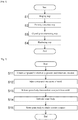
- Fig. 1 is a flowchart showing a flow of producing a high temperature component.
- the production process of the high temperature component includes a shaping step (step S1) of shaping a powder compact of a desired high temperature component shape from an alloy powder, a porosity reduction step (step S2) of reducing a porosity by pressurizing the shaped powder compact, and a crystal grain coarsening step (step S3) of coarsening a crystal grain size of the powder compact with reduced porosity by heat treatment.
- the production process of the high temperature component may further include a hardening step (step S4) of hardening the powder compact with the coarsened grain size after the crystal grain coarsening step (step S3), depending on the type of alloy.
- a powder compact is shaped from an alloy powder using a specific powder shaping method.
- the powder compact has a substantially desired high temperature component shape (net shape, near net shape) although some deformation in the porosity reduction step (step S2) and the heat treatment steps (step S3 and step S4) is taken into account, which will be described later.
- MIM is adopted as a powder shaping method.
- the shaping method of the powder compact is not limited to MIM, and a powder shaping method other than the powder forging method may be adopted.
- a powder shaping method involves collecting an alloy powder into a high temperature component shape and sintering it.
- any one of MIM, press compression shaping, hot isostatic pressing (HIP), cold isostatic pressing (CIP), and additive manufacturing (AM) may be adopted.
- HIP hot isostatic pressing
- CIP cold isostatic pressing
- AM additive manufacturing
- an intermediate product is formed by compression shaping an alloy powder in a mold having a desired high temperature component shape, and the intermediate product is sintered to obtain a powder compact.
- an alloy powder is filled into a high temperature component-shaped capsule, an intermediate product is formed by applying uniform high pressure and high temperature to the capsule, and the intermediate product is sintered to obtain a powder compact.
- an alloy powder is sealed in a high temperature component shape, a uniform liquid pressure is applied thereto to form an intermediate product, and the intermediate product is sintered to obtain a powder compact.
- an alloy powder is melted and solidified by layer with a laser or an electron beam to form a powder compact having a desired shape.
- a method including plastic working such as forging, extrusion, rolling and drawing is not used as the shaping method of the powder compact.
- cold plastic working and isothermal plastic working below the recrystallization temperature of the material such that dislocations due to plastic strain applied to the material remain are not used for shaping a powder compact.
- Fig. 2 is a flowchart of treatment of the shaping step.
- step S1 first, an alloy powder and a binder are uniformly kneaded to obtain a compound thereof (step S11).
- the compound is shaped into pellets with good moldability using a pelletizer.
- the binder may be those conventionally commonly used in MIM, and examples thereof include at least one of polypropylene (PP), polyethylene (PE), polyacetal (POM), polymethyl methacrylate (PMMA), carnauba wax (CW), paraffin wax (PW), stearic acid (St), and the like.
- This alloy powder is a Ni-based alloy powder containing 0.002% or more and 0.02% or less of C and 5.40% or more and 8.40% or less of Al + Ti by mass percentage.
- This alloy powder may contain, in addition to the above C, Al and Ti, 4.60% or less (including 0%) of Nb + Ta, 5.00% or more and 22.80% or less of Cr, 19.50% or less (including 0%) of Co, 1.80% or more and 13.75% or less of Mo + W, 0.10% or less (excluding 0%) of B, 1.0% or less (excluding 0%) of Zr, 2.0% or less (including 0%) of Hf by mass percentage, and Ni and impurities as the balance.
- the alloy powder has an average particle diameter of 20 ⁇ m or more and 60 ⁇ m or less, and desirably 30 ⁇ m or more and 50 ⁇ m or less.
- the average particle diameter is represented by a volume-based median diameter (d50).
- the volume-based median diameter is defined as a particle diameter at a volume-based relative particle amount of 50% based on particle size distribution (cumulative distribution) obtained by measuring a sample using a particle size distribution measuring device with a laser diffraction/scattering method as a measurement principle. This average particle diameter is larger than the average particle diameter (about 10 ⁇ m) of metal powders used in conventional general MIM.
- the compound obtained as described above is injected into a cavity of a desired high temperature component shape of a mold using an injection molding machine (step S12). Then, the mold is opened, and a green body (intermediate compact) is released from the mold (step S13).
- the green body is obtained by injection molding a compound that is a kneaded product of an alloy powder and a binder.
- Debindering methods include a debindering method by immersing the green body in an organic solvent or water, and a debindering method by heating the green body in a debindering furnace at 100 to 600°C.
- the debindered green body is sintered to obtain a powder compact (step S15).
- the debindered green body is generally heated at 1200 to 1300°C for 0.5 to 3 hours.
- the sintering conditions used are determined also in consideration of economics so that temperature and time are combined to sufficiently densify the powder compact (for example, a specific density of 95% or more).
- This sintering step may be performed continuously with the above-described debindering step.
- the process of the shaping step of the powder compact is controlled such that the carbon content of the powder compact is 0.002% or more and 0.07% or less (desirably 0.006% or more and 0.07% or less, and further preferably greater than 0.03% and 0.07% or less) by mass percentage.
- the carbon content of the alloy powder is limited to 0.002% or more and 0.02% or less.
- step S2 a gas pressure is applied to the powder compact so as to reduce the porosity of the powder compact obtained in the shaping step (step S1). Since pores in the powder compact can also be a pinning factor that inhibits the growth of crystal grains, the smaller the porosity of the powder compact after the porosity reduction step (step S2), the better.
- step S2 for example, HIP (hot isostatic pressing) is used.
- HIP hot isostatic pressing
- a gas pressure a high temperature of 900 to 1300°C and an isotropic pressure of several tens to 200 MPa are simultaneously applied to a powder compact that is an object to be treated.
- the type of gas to be used in HIP is an inert gas (for example, Ar).
- HIP parameters can be changed according to alloy composition and target cycle time of the treatment, it is preferable to set the temperature, pressure and time to a degree sufficient to substantially eliminate the porosity of the powder compact.
- step S3 a coarsening heat treatment for coarsening the crystal grains of the powder compact is performed.
- the powder compact is heated at a predetermined coarsening temperature for a predetermined coarsening time in a vacuum or an inert gas atmosphere.
- the "vacuum atmosphere” refers to a space state where the pressure is less than 1000 Pa.
- the "inert gas atmosphere” refers to a space state replaced with an inert gas such as Ar of 1000 Pa or more.
- carbides composed of metal atoms such as Ti, Nb, Ta, Hf, Mo, Cr and Ni and carbon atoms contained in the alloy are present.
- M 23 C 6 carbide in which Cr, Mo and the like are bonded with C in a ratio of about 23 : 6 and the like are known (“M” represents a metal element).
- the MC carbide is the most stable at high temperature, and the inventors of the present application consider that carbides present at the crystal grain boundaries of the powder compact, mainly MC carbides, exhibit a pinning force to hinder grain boundary migration. Moreover, it has been found from experiments that this pinning effect sharply drops at a certain temperature. Hereinafter, a temperature at which the pinning effect sharply drops is referred to as "pinning effect disappearance temperature”.
- the pinning effect disappearance temperature varies depending on the composition of the alloy, and even alloys of similar compositions are considered to have different pinning effect disappearance temperatures depending on the carbon content. Therefore, the pinning effect disappearance temperature is experimentally obtained in advance, and the coarsening temperature is set to a temperature equal to or higher than the pinning effect disappearance temperature and equal to or lower than the solidus temperature of the powder compact.
- the solidus temperature of the powder compact is a temperature at which a liquid phase is first generated from the powder compact, and depends on the composition of the powder compact and its carbon content.
- Fig. 5 shows an example of a DSC thermogram obtained by measuring the powder compact with a differential scanning calorimeter (DSC).
- the differential scanning calorimeter is a device which measures the temperature of a reference substance and a sample while applying a certain amount of heat to the sample, captures thermal properties of the sample as a temperature difference, and measures endothermic and exothermic reactions due to a state change of the sample.
- the vertical axis represents heat flow [mJ/s]
- the horizontal axis represents temperature [°C].
- the coarsening time is influenced by the coarsening temperature, in addition to the shape of the powder compact and the carbon content.
- the longer the coarsening time the greater the degree of coarsening of the crystal grains, but it is uneconomical when the coarsening time is long. Therefore, the coarsening time may be determined from a balance between the size of crystal grains for high temperature components to have desired creep resistance and economical efficiency, based on the results obtained through experiments.
- the porosity reduction step (step S2) is performed between the shaping step (step S1) and the crystal grain coarsening step (step S3), but the porosity reduction step (step S2) may be performed simultaneously with the crystal grain coarsening step (step S3). Further, as will be described later, when omitting the porosity reduction step (step S2), the crystal grain coarsening step (step S3) may be performed continuously with the sintering treatment in the shaping step (step S1).
- step S4 predetermined solution treatment and aging treatment are performed for each alloy, and an appropriate ⁇ ' phase is dispersed and precipitated in a parent phase. These conditions are determined in consideration of the required mechanical characteristics. Some alloys exhibit strength without being subjected to hardening treatment (step S4), by slow cooling after the crystal grain coarsening step (step S3). Further, the solution treatment can be omitted by rapid cooling after the crystal grain coarsening step (step S3). High temperature components can be produced by the above steps (S1 to S4 or S1 to S3).
- the method for producing a high temperature component described above includes a shaping step (step S1) of shaping a powder compact of a desired high temperature component shape, using a specific powder shaping method (other than a powder forging method) from an alloy powder of ⁇ ' precipitation strengthening-type Ni-based alloy, a porosity reduction step (step S2) of reducing a porosity by applying an isotropic pressure to the shaped powder compact using a gas pressure, and a crystal grain coarsening step (step S3) of coarsening crystals of the powder compact by heat treatment.
- the porosity reduction step (step S2) and the crystal grain coarsening step (step S3) may proceed simultaneously. Further, after the crystal grain coarsening step (step S3), a heat treatment for precipitating the ⁇ ' phase from the powder compact with the coarsened crystal grain size may be performed.
- the shaping step involves collecting the alloy powder into a high temperature component shape and sintering it.
- a powder shaping method any one of metal powder injection shaping, press compression shaping, hot isostatic pressing, cold isostatic pressing, and additive manufacturing may be adopted.
- the powder compact contains 0.002% or more and 0.07% or less of C and 5.40% or more and 8.40% or less of Al + Ti by mass percentage.
- This powder compact may contain, in addition to the above C, Al and Ti, 4.60% or less (including 0%) of Nb + Ta, 5.00% or more and 22.80% or less of Cr, 19.50% or less (including 0%) of Co, 1.80% or more and 13.75% or less of Mo + W, 0.10% or less (excluding 0%) of B, 1.0% or less (excluding 0%) of Zr, and 2.0% or less (including 0%) of Hf by mass percentage.
- the powder compact may contain greater than 0.03% and 0.07% or less of C, 6.00% or more and 7.50% or less of Al + Ti, 1.50% or more and 3.00% or less of Nb + Ta, 11.00% or more and 15.00% or less of Cr, 3.80% or more and 5.20% or less of Mo, 0.005% or more and 0.020% or less of B, and 0.05% or more and 0.20% or less of Zr by mass percentage, with the balance being made up of Ni and inevitable impurities, which corresponds to IN713LC and alloy ⁇ in Table 2.
- a high temperature component having such a composition becomes a ⁇ ' precipitation strengthening-type Ni-based alloy having excellent creep resistance.
- the content of C that is present at the crystal grain boundaries of the powder compact and generates carbides that are thought to inhibit crystal growth is limited, and the crystal grain size grows from the grain size of the alloy powder by undergoing the crystal grain coarsening step.
- the growth of the crystal grain size is expected to improve the creep resistance of high temperature components. That is, according to the method for producing a high temperature component, it is possible to produce, from a metal powder, a high temperature component made of a ⁇ ' precipitation strengthening-type Ni-based alloy having excellent high-temperature characteristics using a shaping method other than forging such as MIM.
- a high temperature component made of a ⁇ ' precipitation strengthening-type Ni-based alloy containing 0.002% or more and 0.07% or less of C, and 5.40% or more and 8.40% or less of Al + Ti by mass percentage, in which the average size of crystal grains is 150 ⁇ m or more, and the structure of the crystal grains is equiaxed in all cross sections in three orthogonal directions and non-dendritic structure.
- the powder compact in the method for producing a high temperature component, in the crystal grain coarsening step, is heated at a predetermined coarsening temperature in a vacuum atmosphere or an inert gas atmosphere.
- the "coarsening temperature” is a temperature in the range of equal to or higher than the pinning effect disappearance temperature inherent to the powder compact and equal to or lower than the solidus temperature of the powder compact.
- the heat treatment for crystal grain coarsening is performed at the temperature in the range of equal to or higher than the pinning effect disappearance temperature at which the pinning effect of the carbides present at the grain boundaries of the powder compact sharply drops and equal to or lower than the solidus temperature of the powder compact, whereby there is no obstacle to the grain boundary migration of the powder compact, so that growth of crystal grains is expected to be promoted.
- the shaping step includes injecting a compound obtained by kneading the alloy powder and the resin binder into a mold to shape an intermediate compact (green body), debindering the intermediate compact, and sintering the debindered intermediate compact to obtain the powder compact.
- a high temperature component with high shape accuracy can be obtained by using MIM to obtain a powder compact shaped into a shape of a high temperature component. Furthermore, by using MIM, the material yield is high, material costs and post-processing costs can be reduced, and production running time is relatively short, and thus an improvement in productivity can be expected.
- the volume-based average particle diameter (d50) of the alloy powder is set to 20 ⁇ m or more and 60 ⁇ m or less.
- the alloy powder used in MIM contains 0.002% or more and 0.02% or less of C by mass percentage.
- the content of C in the powder compact can be suppressed to 0.07% or less.
- a compound obtained by uniformly kneading an alloy powder and a binder was injected into a mold to obtain a plate-like green body with a thickness of about 1 to 3 mm.
- the binder used was a mixture of PP, POM and PW, or a mixture of PP, PMMA and PW, depending on the sample.
- Table 4 shows the ratio (mass percentage) of elements contained in the alloy powder of each sample.
- the alloy powders of Samples a1 to a6, b1 to b7, c1 to c5, d1 to d12, e1 to e6, f1, g1, and h1 were obtained by changing in the ratio of C from the composition of "alloy ⁇ " in Table 2.
- the average particle diameter (d50) of the alloy powders is 48.0 ⁇ m in all cases except for Samples a1 to a4, f2, and g2 described later.
- the obtained green body was heated and debindered while gradually raising the temperature from room temperature to 500°C, and further continuously heated under appropriate sintering conditions (furnace temperature and time) so that sufficient densification proceeded to obtain a powder compact.
- the powder compacts obtained in the step S1 were subjected to HIP under conditions of 1204°C, 4 hours, and 102 to 104 MPa Ar atmosphere. In some samples, this HIP was intentionally omitted.
- the powder compacts whose pores were reduced by the step S2 were heated at a coarsening temperature in a vacuum or an Ar atmosphere for a coarsening time.
- the coarsening temperature and the coarsening time were different for each sample.
- the plate-like sample was cut so that the thickness direction was included in the visual field and then embedded in a resin, the cut surface was polished, etched with a marble liquid, and the cut surface was imaged with an optical microscope. Then, using a structural photograph (image) obtained by imaging, the average grain size of crystals was determined by the following procedures (1) to (3). In addition, when sharpness of the image was insufficient for evaluation of the crystal grain size in the entire thickness direction in one structural photograph, a combined photograph of a plurality of structural photographs was used as the structural photograph. In addition, the imaging range of structural photographs was set so that the aspect ratio of the thickness direction and the straight direction thereof was about 1 : 1.
- one evaluated as “coarsened (A)” has an average crystal grain size of 150 ⁇ m or more, and a crystal grain structure thereof is an equiaxed in all cross sections in three orthogonal directions and non-dendritic structure.
- A* 1 un-coarsened crystal grains
- 10 or more crowds of crystal grains with an average crystal grain size of 100 ⁇ m or less are confirmed in the structural photograph.
- A* 2 partial melting is observed at the grain boundaries in the structural photograph.
- a plate-like sample was cut into a faceted shape with a drill or the like, and the carbon content of the powder compact was measured using a non-dispersive infrared absorption table method.
- the carbon content on the outermost surface of the sample may be measured low due to the difference in properties for removing binder, it was noted that facets were collected from within the sample.
- step S1 an experiment was conducted to verify that the carbon content of the powder compact can be reduced depending on the alloy powder size.
- Sample a1 was obtained by the above-described sample preparation procedure, using an alloy powder with an average particle diameter (d50) of 10.9 ⁇ m, at a coarsening temperature of 1280°C, for a coarsening time of 12 hours, in a coarsening atmosphere of 10 kPa Ar atmosphere.
- the carbon content of the powder compact of Sample a1 was 0.074% by mass.
- Sample a2 was obtained by the above-described sample preparation procedure, using an alloy powder with an average particle diameter (d50) of 23.6 ⁇ m, at a coarsening temperature of 1280°C, for a coarsening time of 12 hours, in a coarsening atmosphere of 10 kPa Ar atmosphere.
- the carbon content of the powder compact of Sample a2 was 0.050% by mass.
- Samples a3 to a4 were obtained by the above-described sample preparation procedure, using an alloy powder with an average particle diameter (d50) of 30.7 ⁇ m, at a coarsening temperature of 1280°C, for a coarsening time of 12 hours, in a coarsening atmosphere of 10 kPa Ar atmosphere.
- the carbon content of the powder compact of Sample a3 was 0.061% by mass, and the carbon content of the powder compact of Sample a4 was 0.046% by mass.
- Samples a5 to a6 were obtained by the above-described sample preparation procedure, using an alloy powder with an average particle diameter (d50) of 48.0 ⁇ m, at a coarsening temperature of 1280°C, for a coarsening time of 12 hours, in a coarsening atmosphere of 10 kPa Ar atmosphere.
- the carbon content of the powder compact of Sample a5 was 0.058% by mass, and the carbon content of the powder compact of Sample a6 was 0.034% by mass.
- Table 6 shows characteristics of the alloy powders of Samples a1 to a6, and observation and evaluation results of these samples. As is apparent from Table 6, in Sample a1, while coarsened crystal grains were observed even inside the cross section of the sample, the average crystal grain size did not satisfy the predetermined standard (150 ⁇ m or more). In Samples a2 to a6, coarsening of the crystal grain size was observed. In Samples a2 to a6, while the carbon content of the alloy powders is the same, the average particle diameter of the alloy powders is different, so that the content of the powder compacts is different. Therefore, Samples a2 to a6 showed differences in the degree of coarsening of the crystal grain size and the distribution of crystal grains with insufficient coarsening.
- step S1 an experiment was conducted to verify crystal grain growth due to differences in carbide-forming elements contained in the alloy powder.
- Sample h1 was obtained by the above-described sample preparation procedure, using an alloy powder with an average particle diameter (d50) of 48.0 ⁇ m, at a coarsening temperature of 1280°C, for a coarsening time of 12 hours, in a coarsening atmosphere of 10 kPa Ar atmosphere.
- elements that combine with C to form MC carbide are Ti and Nb.
- Sample h2 was obtained by the same sample preparation procedure as Sample h1, by adding powder Ta with an average particle diameter of 25 ⁇ m to the alloy powder used in Sample h1 at a ratio of 1.65% by mass.
- elements that combine with C to form MC carbide are Ti, Nb, and Ta.
- Sample h3 was obtained by the same sample preparation procedure as Sample h1, by adding powder Hf with an average particle diameter of 25 ⁇ m to the alloy powder used in Sample h1 at a ratio of 1.50% by mass.
- elements that combine with C to form MC carbide are Ti, Nb, and Hf.
- Sample No. Characteristics of alloy powder Carbon content of powder compact [% by mass] Observation and evaluation results Carbon content [% by mass] Average particle diameter [ ⁇ m] MC carbide forming elements h1 0.006 48.0 Ti, Nb 0.058 A h2 0.006 48.0 Ti, Nb, Ta 0.049 A h3 0.006 48.0 Ti, Nb, Hf 0.058 A
- Table 7 shows characteristics of the alloy powders of Samples h1, h2, and h3, and observation and evaluation results of these samples. As is apparent from Table 7, coarsening of the crystal grain size was observed in any of Samples h1, h2, and h3. From the above, it has been found that, in an alloy containing at least one element of Ti, Nb, Ta, and Hf, coarsening of the crystal grain size is exhibited by limiting the carbon content of the powder compact.
- step S3 In the crystal grain coarsening step (step S3), an experiment was conducted to verify an appropriate coarsening time.
- Samples b1 to b4 with different coarsening times were obtained by the above-described sample preparation procedure, at a coarsening temperature of 1280°C, for different coarsening times of 1, 2, 4, and 12 hours, in a coarsening atmosphere of 10 kPa Ar atmosphere.
- the carbon content of the powder compact was 0.034 to 0.058% by mass.
- Table 8 shows observation and evaluation results of Samples b1 to b7 with different coarsening times.
- coarsening of the crystal grain size was confirmed when the coarsening time was 2 hours or longer, and good coarsening of the crystal grain size with no uneven distribution of un-coarsened crystal grains were observed after 4 hours or longer.
- the vacuum atmosphere coarsening of the crystal grain size was confirmed at a coarsening time of 4 hours or longer, but evaporation of Cr was observed.
- Sample b7 partial melting was also observed. From the above, it has been found that the crystal grain size becomes coarse when the coarsening time is 2 hours or longer, but the coarsening time is desirably 4 hours or longer.
- step S3 In the crystal grain coarsening step (step S3), an experiment was conducted to verify an appropriate coarsening atmosphere.
- Samples c1 to c5 with different coarsening atmospheres were obtained by the above-described sample preparation procedure, at a coarsening temperature of 1280°C, for a coarsening time of 4 hours, in different coarsening atmospheres of a vacuum atmosphere lower than 10 -2 Pa, 100 Pa Ar atmosphere, 1300 Pa Ar atmosphere, 10 kPa Ar atmosphere, and 104 MPa Ar atmosphere.
- the carbon content of the powder compact was 0.034 to 0.058% by mass.
- Table 9 shows observation and evaluation results of Samples c1 to c5 with different coarsening atmospheres. As is apparent from Table 9, while coarsening of the crystal grain size was confirmed in any of Samples c1 to c5, the evaporation of Cr was observed in Samples c1 and c2, and partial melting was observed in Sample c5. In Samples c3 and c4, good coarsening of the crystal grain size was observed. Based on this, it has been found that the evaporation of Cr can be suppressed by setting the coarsening atmosphere to an inert gas atmosphere higher than 100 Pa.
- step S3 In the crystal grain coarsening step (step S3), an experiment was conducted to verify an appropriate coarsening temperature.
- Samples with different coarsening temperatures and coarsening atmospheres among the coarsening conditions were prepared, and observed and evaluated, respectively.
- Samples d1 to d6 were obtained by the above-described sample preparation procedure, at different coarsening temperatures of 1300, 1280, 1260, 1250, 1240, and 1220°C as shown in Table 10, for a coarsening time of 12 hours, in a coarsening atmosphere of 10 kPa Ar atmosphere.
- the carbon content of the powder compact was 0.034 to 0.058% by mass.
- Samples d7 to d12 were obtained by the above-described sample preparation procedure, at different coarsening temperatures of 1300, 1280, 1260, 1250, 1240, and 1220°C as shown in Table 10, for a coarsening time of 12 hours, in a coarsening atmosphere of a vacuum atmosphere lower than 10 -2 Pa.
- the carbon content of the powder compact was 0.034 to 0.058% by mass.
- Coarsening temperature [°C] Coarsening atmosphere Observation and evaluation results d1 1300 10kPa Ar A *2 d2 1280 A d3 1260 A d4 1250 A d5 1240 C d6 1220 C d7 1300 ⁇ 10 -2 Pa Vacuum A *2, *3 d8 1280 A *3 d9 1260 A *3 d10 1250 A *3 d11 1240 A *1, *3 d12 1220 C
- Table 10 shows observation and evaluation results of Samples d1 to d12. From Table 10, in Samples d1 to d6, coarsening was confirmed in Sample d4 at a coarsening temperature of 1250°C, and coarsening was not confirmed in Sample d5 at a coarsening temperature of 1240°C, in an Ar atmosphere. From this, it is presumed that, in the alloys of Samples d1 to d6, the pinning effect disappearance temperature in the Ar atmosphere is at 1241°C or higher and 1250°C or lower.
- step S2 An experiment was conducted to verify an influence of the porosity reduction step (step S2) included in the method for producing a high temperature component on the coarsening temperature of the crystal grain coarsening step (step S3).
- Samples e1 and e2 were obtained by the above-described sample preparation procedure in which HIP as a porosity reduction treatment (procedure (iii)) was omitted, at different coarsening temperatures of 1300, 1280°C as shown in Table 11, for a coarsening time of 12 hours, in a coarsening atmosphere of 10 kPa Ar atmosphere.
- the carbon content of the powder compact was 0.034 to 0.058% by mass.
- Samples e3 to e6 were obtained by the above-described sample preparation procedure in which HIP as a porosity reduction treatment (procedure (iii)) was omitted, at different coarsening temperatures of 1300, 1280, 1260°C as shown in Table 11, for a coarsening time of 12 hours, in a coarsening atmosphere of a vacuum atmosphere lower than 10 -2 Pa.
- the carbon content of the powder compact was 0.034 to 0.058% by mass.
- Table 11 shows observation and evaluation results of Samples e1 to e5. From Table 11, it is apparent that a high temperature component made of a ⁇ ' precipitation strengthening-type Ni-based alloy with the coarsened crystal grain size can be obtained, also by the above-described method for producing a high temperature component in which the porosity reduction step (step S2) is omitted, that is, a method for producing a high temperature component including a shaping step (step S1) of shaping a powder compact of a desired high temperature component shape from a Ni-based alloy powder and a crystal grain coarsening step (step S3) of coarsening a crystal grain size of the powder compact by heat treatment.
- a shaping step step S1 of shaping a powder compact of a desired high temperature component shape from a Ni-based alloy powder
- step S3 crystal grain coarsening step
- the crystal grains did not become coarse at a coarsening temperature of 1280°C, it is inferred that the pinning effect disappearance temperature when omitting the porosity reduction step is at 1281°C or higher and 1300°C or lower.
- the crystal grains did not become coarse at a coarsening temperature of 1260°C, it is inferred that the pinning effect disappearance temperature when omitting the porosity reduction step is at 1261°C or higher and 1280°C or lower.
- Table 12 shows pinning effect disappearance temperatures presumed from the verification experiment results regarding the coarsening temperature above.
- Table 13 shows measurement results of the solidus temperature and liquidus temperature of the powder compacts having carbon contents of 0.034 to 0.058% by mass and 0.10% by mass.
- Average particle diameter of alloy powder [ ⁇ m] Carbon content of powder compact [% by mass] Pinning effect disappearance temperature [°C] Without porosity reduction step With porosity reduction step 10 kPa Ar ⁇ 10 -2 Pa Vacuum 10 kPa Ar ⁇ 10 -2 Pa Vacuum 48.0 0034-0.058 1281-1300 1261-1280 1241-1250 1221-1240
- the solidus temperature and liquidus temperature were measured as follows. Samples f1 and f2 of powder compacts with different carbon contents of 0.034 to 0.058% by mass and 0.10% by mass were prepared, and each sample was measured with a differential scanning calorimeter (DSC). Based on the results, the solidus temperature and liquidus temperature of each sample were determined.
- the powder compact of Sample f1 was molded by MIM as shown in the step S1 of the above-described sample preparation procedure, whereas the powder compact of Sample f2 was shaped by hot isostatic pressing (HIP).
- the powder compact of Sample f2 was obtained by sealing an alloy powder having a predetermined composition shown in Table 4 and an average particle diameter (d50) of 26.9 ⁇ m in a can made of mild steel and performing hot isostatic pressing at 1204°C for 4 hours in 104 MPa Ar atmosphere, and finally removing the mild steel.
- step S3 in order to coarsen the crystal grain size of the powder compact at a relatively low coarsening temperature in the crystal grain coarsening step (step S3), it is preferable to perform the porosity reduction step (step S2) without omission.
- the solidus temperature is lowered when the carbon content of the powder compact is large. Since the crystal grain coarsening heat treatment temperature is equal to or higher than the pinning effect disappearance temperature and equal to or lower than the solidus temperature, it can be said that the carbon content of the powder compact is preferably small in order to expand the window.
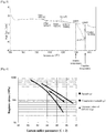
- test pieces and comparative test pieces were prepared by the following method, and a creep rupture test was performed in accordance with ASTM E139.
- Sample g1 was obtained by the above-described sample preparation procedure, at a coarsening temperature of 1280°C, for a coarsening time of 12 hours, in a coarsening atmosphere of 10 kPa Ar atmosphere. From Sample g1, test piece g1' with a gauge length of 12 mm and a size of 3.2 mm in width and 1.5 to 2 mm in thickness was prepared. It is to be noted that the shape of the test piece g1' deviates from the standard of ASTM E139. A creep rupture test was performed on the test piece g1' while changing the test conditions between 927°C/227 MPa and 980°C/90 MPa.
- Comparative Sample g2 was obtained by the same procedure except that, using the alloy powder having a predetermined composition shown in Table 4 and an average particle diameter (d50) of 26.9 ⁇ m by mass percentage, the coarsening step (step S3) in the above-described sample preparation procedure was omitted, and the solution treatment was performed at 1176°C for 2 hours in the hardening treatment (step S4) and then the aging treatment was performed at 925°C for 16 hours.
- the content of C in the powder compact of Comparative Sample g2 was 0.12% by mass. From Comparative Sample g2, comparative test piece g2' with a gauge length of 16 to 20 mm and a size of ⁇ 4 mm was prepared.
- a creep rupture test was performed on the test piece g2' while changing the test conditions among 927°C/227 MPa, 980°C/90 MPa, 760°C/690 MPa, 816°C/172 MPa, 927°C/90 MPa, 927°C/50 MPa.
- Fig. 6 shows the results of plotting the creep rupture test results in terms of Larson-miller parameter.
- literature values of In713C cast described in " SUPERALLOYS II" Chester T. Sims, Norman S. Stoloff, William C. Hagel (1987 ) are also included for comparison.
Landscapes
- Chemical & Material Sciences (AREA)
- Engineering & Computer Science (AREA)
- Mechanical Engineering (AREA)
- Materials Engineering (AREA)
- Metallurgy (AREA)
- Organic Chemistry (AREA)
- Manufacturing & Machinery (AREA)
- Physics & Mathematics (AREA)
- Thermal Sciences (AREA)
- Crystallography & Structural Chemistry (AREA)
- Fluid Mechanics (AREA)
- Powder Metallurgy (AREA)
Applications Claiming Priority (2)
| Application Number | Priority Date | Filing Date | Title |
|---|---|---|---|
| PCT/JP2017/019037 WO2018216067A1 (fr) | 2017-05-22 | 2017-05-22 | Composant à haute température et procédé de production associé |
| PCT/JP2018/018416 WO2018216514A1 (fr) | 2017-05-22 | 2018-05-11 | Composant à haute température et procédé de production associé |
Publications (2)
| Publication Number | Publication Date |
|---|---|
| EP3633052A1 true EP3633052A1 (fr) | 2020-04-08 |
| EP3633052A4 EP3633052A4 (fr) | 2021-02-17 |
Family
ID=64395359
Family Applications (1)
| Application Number | Title | Priority Date | Filing Date |
|---|---|---|---|
| EP18805974.5A Pending EP3633052A4 (fr) | 2017-05-22 | 2018-05-11 | Composant à haute température et procédé de production associé |
Country Status (5)
| Country | Link |
|---|---|
| US (2) | US11326230B2 (fr) |
| EP (1) | EP3633052A4 (fr) |
| JP (3) | JP6913163B2 (fr) |
| TW (1) | TW201908499A (fr) |
| WO (2) | WO2018216067A1 (fr) |
Cited By (1)
| Publication number | Priority date | Publication date | Assignee | Title |
|---|---|---|---|---|
| CN114737084A (zh) * | 2022-06-07 | 2022-07-12 | 中国航发北京航空材料研究院 | 高强抗蠕变高温合金及其制备方法 |
Families Citing this family (20)
| Publication number | Priority date | Publication date | Assignee | Title |
|---|---|---|---|---|
| GB2565063B (en) | 2017-07-28 | 2020-05-27 | Oxmet Tech Limited | A nickel-based alloy |
| KR102443966B1 (ko) * | 2018-11-30 | 2022-09-19 | 미츠비시 파워 가부시키가이샤 | Ni기 합금 연화 분말 및 해당 연화 분말의 제조 방법 |
| JP7141967B2 (ja) * | 2019-03-12 | 2022-09-26 | 川崎重工業株式会社 | 造形体製造方法、中間体および造形体 |
| JP7218225B2 (ja) * | 2019-03-22 | 2023-02-06 | 三菱重工業株式会社 | 積層造形用合金粉末、積層造形物及び積層造形方法 |
| FR3095143B1 (fr) * | 2019-04-16 | 2021-12-17 | Safran Aircraft Engines | Procédé de fabrication d’une pièce par irradiation localisée d’un matériau par concourance d’au moins deux faisceaux |
| GB2584654B (en) | 2019-06-07 | 2022-10-12 | Alloyed Ltd | A nickel-based alloy |
| FR3097876B1 (fr) * | 2019-06-28 | 2022-02-04 | Safran | Poudre de superalliage, piece et procede de fabrication de la piece a partir de la poudre |
| GB2587635B (en) | 2019-10-02 | 2022-11-02 | Alloyed Ltd | A Nickel-based alloy |
| US11384414B2 (en) | 2020-02-07 | 2022-07-12 | General Electric Company | Nickel-based superalloys |
| US11591683B2 (en) | 2020-02-18 | 2023-02-28 | Pratt & Whitney Canada Corp. | Method of manufacturing nickel based super alloy parts |
| CN112828307A (zh) * | 2020-12-30 | 2021-05-25 | 南方科技大学 | 一种粗化沉淀强化镍基高温合金晶粒的激光粉床熔融成形方法 |
| CN116761690A (zh) * | 2021-01-19 | 2023-09-15 | 西门子能源美国公司 | 用于对超合金部件进行液体辅助增材制造的超合金粉末混合物 |
| US11697865B2 (en) | 2021-01-19 | 2023-07-11 | Siemens Energy, Inc. | High melt superalloy powder for liquid assisted additive manufacturing of a superalloy component |
| CN113560576A (zh) * | 2021-06-18 | 2021-10-29 | 深圳艾利门特科技有限公司 | 超高强高韧钢零件的mim成型工艺 |
| JP2023032514A (ja) * | 2021-08-27 | 2023-03-09 | 国立研究開発法人物質・材料研究機構 | ニッケル基超合金及びその粉末、並びにニッケル基超合金造形体の製造方法 |
| EP4212639B1 (fr) * | 2022-01-18 | 2025-06-04 | Garrett Transportation I Inc. | Alliage à base de nickel et roue de turbine l'incorporant |
| EP4302905A1 (fr) * | 2022-07-05 | 2024-01-10 | EOS GmbH Electro Optical Systems | Superalliage à base de ni |
| JP7202058B1 (ja) | 2022-11-14 | 2023-01-11 | 株式会社エヌ・ティ・ティ・データ・ザムテクノロジーズ | Ni基合金造形物の製造方法、およびNi基合金造形物 |
| JP2024110677A (ja) * | 2023-02-03 | 2024-08-16 | 川崎重工業株式会社 | ニッケル基超合金、ニッケル基超合金粉末および造形体の製造方法 |
| JPWO2024176728A1 (fr) * | 2023-02-21 | 2024-08-29 |
Family Cites Families (17)
| Publication number | Priority date | Publication date | Assignee | Title |
|---|---|---|---|---|
| US4140528A (en) * | 1977-04-04 | 1979-02-20 | Crucible Inc. | Nickel-base superalloy compacted articles |
| US4685977A (en) * | 1984-12-03 | 1987-08-11 | General Electric Company | Fatigue-resistant nickel-base superalloys and method |
| US4832112A (en) * | 1985-10-03 | 1989-05-23 | Howmet Corporation | Method of forming a fine-grained equiaxed casting |
| JP3067416B2 (ja) * | 1992-08-20 | 2000-07-17 | 三菱マテリアル株式会社 | 高温耐熱部品製造用Ni基合金粉末 |
| US5451142A (en) * | 1994-03-29 | 1995-09-19 | United Technologies Corporation | Turbine engine blade having a zone of fine grains of a high strength composition at the blade root surface |
| US5584947A (en) | 1994-08-18 | 1996-12-17 | General Electric Company | Method for forming a nickel-base superalloy having improved resistance to abnormal grain growth |
| US5725692A (en) * | 1995-10-02 | 1998-03-10 | United Technologies Corporation | Nickel base superalloy articles with improved resistance to crack propagation |
| US7387763B2 (en) | 2004-07-27 | 2008-06-17 | General Electric Company | Preparation of sheet by injection molding of powder, consolidation, and heat treating |
| FR2899240B1 (fr) * | 2006-03-31 | 2008-06-27 | Snecma Sa | Alliage a base de nickel |
| GB0719195D0 (en) | 2007-10-02 | 2007-11-14 | Rolls Royce Plc | A nickel base superalloy |
| US20100329883A1 (en) | 2009-06-30 | 2010-12-30 | General Electric Company | Method of controlling and refining final grain size in supersolvus heat treated nickel-base superalloys |
| CA2804402C (fr) | 2010-07-09 | 2018-02-13 | General Electric Company | Alliage a base de nickel, son traitement et les composants formes a partir dudit alliage |
| JP2014070230A (ja) | 2012-09-27 | 2014-04-21 | Hitachi Metals Ltd | Ni基超耐熱合金の製造方法 |
| JP6356800B2 (ja) | 2013-07-23 | 2018-07-11 | ゼネラル・エレクトリック・カンパニイ | 超合金及びそれからなる部品 |
| EP2944402B1 (fr) | 2014-05-12 | 2019-04-03 | Ansaldo Energia IP UK Limited | Post traitement thermique de composants en superalliage renforcé par phase gamme prime fabriqués de manière additive |
| WO2016013433A1 (fr) * | 2014-07-23 | 2016-01-28 | 株式会社Ihi | PROCÉDÉ DE PRODUCTION D'UN COMPOSANT D'ALLIAGE DE Ni |
| WO2016158705A1 (fr) * | 2015-03-30 | 2016-10-06 | 日立金属株式会社 | PROCÉDÉ DE FABRICATION D'UN SUPERALLIAGE À BASE DE Ni ET RÉSISTANT À LA CHALEUR |
-
2017
- 2017-05-22 WO PCT/JP2017/019037 patent/WO2018216067A1/fr not_active Ceased
-
2018
- 2018-05-11 WO PCT/JP2018/018416 patent/WO2018216514A1/fr not_active Ceased
- 2018-05-11 US US16/616,285 patent/US11326230B2/en active Active
- 2018-05-11 JP JP2019519572A patent/JP6913163B2/ja active Active
- 2018-05-11 EP EP18805974.5A patent/EP3633052A4/fr active Pending
- 2018-05-18 TW TW107116925A patent/TW201908499A/zh unknown
-
2021
- 2021-02-15 JP JP2021022143A patent/JP7109608B2/ja active Active
- 2021-02-15 JP JP2021022142A patent/JP7329003B2/ja active Active
-
2022
- 2022-05-09 US US17/739,385 patent/US11773470B2/en active Active
Cited By (1)
| Publication number | Priority date | Publication date | Assignee | Title |
|---|---|---|---|---|
| CN114737084A (zh) * | 2022-06-07 | 2022-07-12 | 中国航发北京航空材料研究院 | 高强抗蠕变高温合金及其制备方法 |
Also Published As
| Publication number | Publication date |
|---|---|
| JP7329003B2 (ja) | 2023-08-17 |
| WO2018216067A1 (fr) | 2018-11-29 |
| WO2018216514A1 (fr) | 2018-11-29 |
| JP2021088776A (ja) | 2021-06-10 |
| JP6913163B2 (ja) | 2021-08-04 |
| JPWO2018216514A1 (ja) | 2020-03-26 |
| US20200087754A1 (en) | 2020-03-19 |
| JP7109608B2 (ja) | 2022-07-29 |
| US11773470B2 (en) | 2023-10-03 |
| TW201908499A (zh) | 2019-03-01 |
| EP3633052A4 (fr) | 2021-02-17 |
| JP2021088775A (ja) | 2021-06-10 |
| US20220267880A1 (en) | 2022-08-25 |
| US11326230B2 (en) | 2022-05-10 |
Similar Documents
| Publication | Publication Date | Title |
|---|---|---|
| US11773470B2 (en) | High temperature component and method for producing same | |
| JP6690789B2 (ja) | 合金材、該合金材を用いた製造物、および該製造物を有する流体機械 | |
| EP3611282B1 (fr) | Poudre en alliage à base de cobalt | |
| KR101237122B1 (ko) | 티타늄 합금의 미세구조 정련 방법 및 티타늄 합금의 고온-고변형률 초가소성 성형방법 | |
| DE60214999T2 (de) | GIEßEN VON LEGIERUNGEN MIT ISOTROPEN GRAPHITFORMEN | |
| JP5051168B2 (ja) | 窒化物分散Ti−Al系ターゲット及びその製造方法 | |
| WO1996037635A1 (fr) | Materiaux composites comprenant des elements de renfort de matrice metallique | |
| WO2010077735A2 (fr) | Procédé de formation d'alliages d'aluminium de haute résistance contenant des dispersoïdes intermétalliques l12 | |
| JP6011946B2 (ja) | ニッケル基金属間化合物複合焼結材料およびその製造方法 | |
| JP5759426B2 (ja) | チタン合金及びその製造方法 | |
| CN113597476B (zh) | 一种Co基合金结构体的制造方法 | |
| JP5152770B1 (ja) | 強靭超硬合金の製造方法 | |
| US5632827A (en) | Aluminum alloy and process for producing the same | |
| JP6667264B2 (ja) | 高剛性鉄基焼結合金の製造方法 | |
| EP2425027B1 (fr) | Traitement d'aluminides de fer par frittage sans pression de fer et aluminium elementaires | |
| AT10479U1 (de) | Fluiddichte sintermetallteile sowie verfahren zu ihrer herstellung | |
| JP2802587B2 (ja) | 板状wc含有超硬合金の製法 | |
| JP2013170315A (ja) | 強靱超硬合金及び被覆超硬合金 | |
| CN116368255B (zh) | 合金材料、使用该合金材料的合金制造物以及具有该合金制造物的机械装置 | |
| JPH0617486B2 (ja) | 粉末製Ni基超耐熱合金の鍛造方法 | |
| EP0055829A2 (fr) | Alliage à solidification rapide, contenant du bore et procédé pour sa fabrication | |
| JP2013087340A (ja) | ニッケル基金属間化合物焼結体およびその製造方法 | |
| KR20070021115A (ko) | 티타늄 합금의 미세구조 정련 방법 및 티타늄 합금의고온-고변형률 초가소성 성형방법 | |
| Soyama | Development of creep resistant titanium aluminide alloys for the Metal Injection Moulding process |
Legal Events
| Date | Code | Title | Description |
|---|---|---|---|
| STAA | Information on the status of an ep patent application or granted ep patent |
Free format text: STATUS: THE INTERNATIONAL PUBLICATION HAS BEEN MADE |
|
| PUAI | Public reference made under article 153(3) epc to a published international application that has entered the european phase |
Free format text: ORIGINAL CODE: 0009012 |
|
| STAA | Information on the status of an ep patent application or granted ep patent |
Free format text: STATUS: REQUEST FOR EXAMINATION WAS MADE |
|
| 17P | Request for examination filed |
Effective date: 20191204 |
|
| AK | Designated contracting states |
Kind code of ref document: A1 Designated state(s): AL AT BE BG CH CY CZ DE DK EE ES FI FR GB GR HR HU IE IS IT LI LT LU LV MC MK MT NL NO PL PT RO RS SE SI SK SM TR |
|
| AX | Request for extension of the european patent |
Extension state: BA ME |
|
| DAV | Request for validation of the european patent (deleted) | ||
| DAX | Request for extension of the european patent (deleted) | ||
| REG | Reference to a national code |
Ref country code: DE Ref legal event code: R079 Free format text: PREVIOUS MAIN CLASS: C22C0001040000 Ipc: B22F0001000000 |
|
| A4 | Supplementary search report drawn up and despatched |
Effective date: 20210115 |
|
| RIC1 | Information provided on ipc code assigned before grant |
Ipc: C22C 19/05 20060101ALI20210111BHEP Ipc: B22F 3/10 20060101ALI20210111BHEP Ipc: C22C 1/04 20060101ALI20210111BHEP Ipc: C22F 1/10 20060101ALI20210111BHEP Ipc: B22F 3/22 20060101ALI20210111BHEP Ipc: C22C 19/00 20060101ALI20210111BHEP Ipc: B22F 1/00 20060101AFI20210111BHEP Ipc: C22F 1/00 20060101ALI20210111BHEP Ipc: C22C 19/03 20060101ALI20210111BHEP |
|
| STAA | Information on the status of an ep patent application or granted ep patent |
Free format text: STATUS: EXAMINATION IS IN PROGRESS |
|
| 17Q | First examination report despatched |
Effective date: 20230814 |