EP3640425A1 - Dispositif de réception d'une plaque de garde-corps - Google Patents
Dispositif de réception d'une plaque de garde-corps Download PDFInfo
- Publication number
- EP3640425A1 EP3640425A1 EP19020572.4A EP19020572A EP3640425A1 EP 3640425 A1 EP3640425 A1 EP 3640425A1 EP 19020572 A EP19020572 A EP 19020572A EP 3640425 A1 EP3640425 A1 EP 3640425A1
- Authority
- EP
- European Patent Office
- Prior art keywords
- side stop
- support arm
- railing plate
- holder
- recess
- Prior art date
- Legal status (The legal status is an assumption and is not a legal conclusion. Google has not performed a legal analysis and makes no representation as to the accuracy of the status listed.)
- Granted
Links
Images

Classifications
-
- E—FIXED CONSTRUCTIONS
- E04—BUILDING
- E04F—FINISHING WORK ON BUILDINGS, e.g. STAIRS, FLOORS
- E04F11/00—Stairways, ramps, or like structures; Balustrades; Handrails
- E04F11/18—Balustrades; Handrails
- E04F11/181—Balustrades
- E04F11/1817—Connections therefor
-
- E—FIXED CONSTRUCTIONS
- E04—BUILDING
- E04F—FINISHING WORK ON BUILDINGS, e.g. STAIRS, FLOORS
- E04F11/00—Stairways, ramps, or like structures; Balustrades; Handrails
- E04F11/18—Balustrades; Handrails
- E04F11/181—Balustrades
- E04F11/1851—Filling panels, e.g. concrete, sheet metal panels
- E04F11/1853—Glass panels
-
- E—FIXED CONSTRUCTIONS
- E06—DOORS, WINDOWS, SHUTTERS, OR ROLLER BLINDS IN GENERAL; LADDERS
- E06B—FIXED OR MOVABLE CLOSURES FOR OPENINGS IN BUILDINGS, VEHICLES, FENCES OR LIKE ENCLOSURES IN GENERAL, e.g. DOORS, WINDOWS, BLINDS, GATES
- E06B9/00—Screening or protective devices for wall or similar openings, with or without operating or securing mechanisms; Closures of similar construction
-
- E—FIXED CONSTRUCTIONS
- E04—BUILDING
- E04F—FINISHING WORK ON BUILDINGS, e.g. STAIRS, FLOORS
- E04F11/00—Stairways, ramps, or like structures; Balustrades; Handrails
- E04F11/18—Balustrades; Handrails
- E04F11/181—Balustrades
- E04F11/1817—Connections therefor
- E04F2011/1831—Connections therefor between balustrade filling members, e.g. panels, and balustrade posts
-
- E—FIXED CONSTRUCTIONS
- E06—DOORS, WINDOWS, SHUTTERS, OR ROLLER BLINDS IN GENERAL; LADDERS
- E06B—FIXED OR MOVABLE CLOSURES FOR OPENINGS IN BUILDINGS, VEHICLES, FENCES OR LIKE ENCLOSURES IN GENERAL, e.g. DOORS, WINDOWS, BLINDS, GATES
- E06B9/00—Screening or protective devices for wall or similar openings, with or without operating or securing mechanisms; Closures of similar construction
- E06B9/01—Grilles fixed to walls, doors, or windows; Grilles moving with doors or windows; Walls formed as grilles, e.g. claustra
- E06B2009/015—Mounting details
-
- E—FIXED CONSTRUCTIONS
- E06—DOORS, WINDOWS, SHUTTERS, OR ROLLER BLINDS IN GENERAL; LADDERS
- E06B—FIXED OR MOVABLE CLOSURES FOR OPENINGS IN BUILDINGS, VEHICLES, FENCES OR LIKE ENCLOSURES IN GENERAL, e.g. DOORS, WINDOWS, BLINDS, GATES
- E06B9/00—Screening or protective devices for wall or similar openings, with or without operating or securing mechanisms; Closures of similar construction
- E06B9/24—Screens or other constructions affording protection against light, especially against sunshine; Similar screens for privacy or appearance; Slat blinds
Definitions
- the invention relates to a device for receiving a railing plate of a railing arrangement, in particular a glass plate forming a fall protection device on a building opening preferably provided with a lifting and lowering shading device guided in lateral guide rails, with the lower corners of the railing plate assigned to this, receiving it, on a load-bearing plate Pad attachable receiving elements.
- the DE 20 2017 100 178 U1 shows a device for receiving a railing plate, in which the railing plate engages with its side flanks in side guide rails which are provided with lower end caps, which also serve as receiving elements for supporting the railing plate.
- the end caps mentioned are secured relative to the guide rails by horizontal clamping screws which are arranged on pegs which protrude from the end caps of the guide rails and which engage in an associated channel of the associated guide rail.
- the lower end caps forming the receiving elements must be attached to the guide rails before assembly, which is cumbersome.
- the end caps are always at the lower end of the guide rails, so that no variability in height is possible. Lateral adjustability with and / or without lateral play of the railing plate which can be accommodated on the receiving elements is also not provided.
- the DE 295 15 491 U1 shows a further device for receiving a railing plate with a base part which can be screwed onto a stationary base, into which an L-shaped engagement element for receiving a corner of the railing plate can be inserted in a suitable manner. Lateral adjustability of the engagement elements with respect to the railing plate is not provided here. It can therefore happen that the lateral play of the railing plate with respect to the engagement elements is too large or too small.
- the receiving elements each have a bracket which can be fixedly attached to the supporting base and has a support arm running parallel to the lower edge of the railing plate, and an engagement device received thereon with a table receiving the railing plate and a side stop flanking the railing plate on the side, which is adjustable with respect to the railing plate and for this purpose has a corresponding degree of freedom of movement with respect to the console, a manually actuatable actuating element being provided for adjusting the side stop, which is adapted to the Lateral stop exerted pushing force transmitted directly or indirectly to the stationary console.
- the table of the engagement device received on the console advantageously offers a large contact surface for the railing plate, so that the associated side stop can have a large displacement path. This ensures that exact horizontal positioning and lateral adjustment of the railing plate can be achieved. Since the console is stationary relative to the engaging device received thereon, the movement for adjusting the side stop takes place between the engaging device or an element of the engaging device and the stationary console, which enables a sensible design and high setting accuracy. As a result, comparatively large side tolerances, which can arise for different reasons, can also be compensated for and any desired play between the side stops and the railing plate can also be set. For example, a comparatively large play can be set for the insertion of the railing plate, which can subsequently be reduced.
- the console can expediently be designed as an L-shaped component, the upright leg of which is designed as a holder which can be fixed on the supporting base and the lying leg forms the support arm, the holder and the support arm projecting therefrom with guide and / or support surfaces for this bearing surfaces of the elements of the engagement device coming into engagement are provided.
- the L-shaped console can be easily attached to the load-bearing base without tipping over and is advantageously possible a large-area support and guidance of the elements of the engagement device and thus overall high accuracy.
- a further particularly preferred measure can consist in the engagement device being constructed in several parts, the table being accommodated on the support surfaces of the support arm and the side stop separate from the table being designed as a displaceable slide which has guide surfaces interacting with the guide surfaces of the holder and the adjusting element attacks on the one hand on the movable side stop and on the other hand on the console or a component connected to it.
- the multi-part design of the engagement device advantageously facilitates the adjustability of the side stops.
- the carriage forming the side stop can be supported and guided independently of the table on the console and can be in engagement with the actuating element, which, on the other hand, can engage the table, which for this purpose is fixed on the support arm receiving it and thus on the console.
- the actuating element which, on the other hand, can engage the table, which for this purpose is fixed on the support arm receiving it and thus on the console.
- the holder and the support arm of the console can expediently have recesses which merge into one another on the sides facing one another and are delimited by lateral edge webs which contain the guide and support surfaces and into which the slide forming the side stop engages with a rear extension which engages with a lower support surface the lower limit of the two recesses rests and cooperates with lateral guide surfaces with the guide surfaces of the holder-side recess.
- a further advantageous measure can consist in the table including a table top resting on the edge webs delimiting the recess on the support arm side and a lower extension engaging between the edge webs on the support arm side, which is designed as an open-ended tunnel and has a transverse web engaging in the tunnel which the control element, which is expediently designed as a cap screw, can rest with its head and which is penetrated by the shaft of the control element, which can be screwed into an associated threaded hole in the lower region of the rear extension of the side stop.
- the use of a cap screw to form the actuating element results in a continuously variable actuating gear.
- the support arm-side recess can expediently be subdivided into a rear area assigned to the attachment of the side stop and a front area assigned to the attachment of the table by a transverse web provided with a recess for the actuating element. This ensures that the table can be easily mounted on the crossbar mentioned, which allows a large support on the console and thus a reliable power flow from the table to the console.
- the said crosspiece can also serve as a stop to limit the actuating movement of the side stop.
- Another preferred embodiment may consist in that the carriage forming the side stop lies on the table and, with a lower pin, engages through a slot in the table and engages in a recess on the support arm side, delimited by the side webs receiving the table, the Adjusting element, which can also be designed as a head screw, expediently interacts with its head with a lower region of the pin and engages with its shaft in a threaded bore in a lower holder region delimiting the recess on the holder side.
- the adjustable side stop is connected directly to the console by the control element, which results in a very simple flow of force.
- the side stop can expediently have an insertion recess, which is assigned to the actuating element and is accessible from above and extends down to the level of the threaded bore of the holder, which has a transverse groove which is assigned to the head of the actuating element and which is delimited below by a web provided with an engagement notch assigned to the head of the actuating element, and above the footbridge, d. H. is open in the area of the level of the holder-side threaded hole, in the adjustment direction at the back and front.
- the head of the adjusting element can simply be inserted in the manner of a sliding block into the insertion recess, which is preferably cruciform in cross section, and can thus be brought into position in a simple manner.
- a tool which can be carried out through a tunnel of an attachment of the table which engages in an associated recess in the support arm can expediently be used for actuating the actuating element which is introduced from above and brought into engagement with the associated engagement notch.
- a particularly advantageous measure can also consist in that in the area of the upper side of the side stop there is an insertion slope that slopes towards the railing plate. This facilitates the introduction of the railing plate, which can usually be lowered from above, between two side stops and can therefore make plate mounting much easier.
- Preferred areas of application of the invention are so-called French balconies serving as fall protection at floor-to-ceiling building openings with railing plates designed as glass plates, wherein the building opening can be assigned a shading device which is arranged in front of the fall protection and guided in lateral guide rails.
- a shading device which is arranged in front of the fall protection and guided in lateral guide rails.
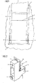
- FIG. 1 denotes a building wall, which is provided with a floor-to-ceiling building opening 2, into which a closure element, not shown, can be inserted, for example in the form of a door arrangement.
- a shading device with a curtain 3 that can be raised and lowered, and a French balcony with a railing plate 4 that acts as a fall protection device. This is usually a glass plate.
- guide rails 5 are mounted over their entire height, into which the curtain 3 and the railing plate 4 engage with their side edges and are thereby guided or held stationary.
- the guide rails 5 are accordingly designed with multiple tracks, one track being associated with the curtain 3 and one track being separated from the railing plate 4 by a web.
- the stationarily arranged railing plate 4 engages with its lower corners in stationarily arranged receiving elements 6, which are placed here in the associated track of the guide rail 5, which support the railing plate 4 horizontally while absorbing their weight and secure their position in the lateral direction.
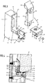
- the receiving elements 6 contain, as from Fig. 2 one can see one on a stationary surface, in the example according to Fig. 1 on the associated guide rail 5 which is fixed to the building, fixable console 7 acting as a supporting lower part and an engagement device 8 acting as an upper part placed thereon for receiving and laterally positioning the in FIG Fig. 2 Railing plate not shown 4.
- the console 7 can, as from Fig.
- bracket 7 can be mortised and screwed to the supporting base, which ensures a reliable stationary, immovable arrangement.
- the console 7 and the engaging device 8 received thereon each how Fig. 2 further shows a two-legged, longitudinally L-shaped configuration.
- the console 7 is fastened with its upright leg, acting as a holder 11, which is provided with the plug pins 9 and the through holes 10, to the associated stationary base, here on the wall side of the associated guide rail 5 running transversely to its longitudinal direction .
- the engagement device 8 received on the bracket 7 contains a table 13 which can be received on the support arm 12 and which has a lying table top for receiving the in Fig. 2 Railing plate 4, not shown in detail, and a side stop 14, which projects perpendicularly to the table 13 and runs parallel to the holder 11 of the console 7.
- the table 13 and the side stop 14 can be formed in one piece.
- the in the 2 to 6 The examples shown are based on a two-part design of the engagement device 8, the standing side stop 14 being movable in relation to the lying table 13 in the longitudinal direction of the support arm 12 and accordingly in the direction of the width of the removable railing plate 4.
- the holder 11 and the support arm 12 projecting therefrom are provided with guide and / or support surfaces for bearing surfaces of the engagement device 8 or the elements of the engagement device 8 that come into engagement therewith.
- the Fig. 3 shows a two-part engagement device 8, wherein the table 13 can be accommodated on associated support surfaces 16 of the support arm 12 and the side stop 14 arranged next to the table 13, which is separate therefrom, is designed as a slide which can be displaced relative to the table 13 and which cooperates with guide surfaces 15 of the holder 11 having.
- the table 13 which can be received with its upper table top on the support arm 12 is not displaceable relative to the support arm 12.
- the table 13 can be made with suitable stops on the associated counter stops on the support arm side abut and / or be tapped or screwed or locked to the support arm 12.
- the table 13 is in Fig. 3 indicated locking bars 17 are provided, which can be snapped into associated locking notches of the support arm 12.
- the two arms of the console 7 are like Fig. 3 can also be seen, provided on the sides facing one another with merging recesses 18, 19 which are delimited by lateral edge webs 20, 21 containing the guide surfaces 15 and support surfaces 16.
- the carriage forming the side stop 14 is provided with a rear extension 22 and thus engages in the recesses 18, 19, the side flanks of the extension 22 interacting with the holder-side guide surfaces 15 and a lower support surface 23 of the extension 22 on the lower limit of the two recesses 18, 19 come to rest and can accordingly be mounted thereon.
- the side stop 14 arranged in its displacement direction next to the table 13 is expediently designed and arranged in such a way that it can run over the facing outward-facing edge of the table 13 with its front stop surface facing the railing plate 4. Accordingly, the abovementioned stop surface ends at the bottom, as from Fig. 2 can be seen, at least at the level of the table surface or preferably with movement play above it, so that there is an in at the lower end of the abovementioned stop surface Fig. 4 designated level 48 results.
- the table 13 contains a projection 24 which protrudes downwards from the table top which can be brought to rest on the support arm-side support surfaces 15 and which engages between the support arms on the side of the support arm 12 between the support arm side edge webs 21.
- the shoulder 24 bears the locking strips 17 mentioned above and laterally projecting lugs 25 which can be brought into engagement in the associated end recesses 26 of the edge webs 21.
- the table 13 thus formed is accordingly latched and mortised in the assembled state with the support arm 12.
- the lower neck 24 has one down open cross section, so that there is a practically downwardly open tunnel 27. This can be done by a Fig. 3 with broken lines indicated, from the table top protruding down crosspiece 28 may be interrupted.
- the recess 19 on the support arm side can be interrupted by a cross piece 29 and thereby divided into a rear area assigned to the rear extension 22 of the side stop 14 and a front area assigned to the lower extension 24 of the table 13.
- the crosspiece 29 can form a stop limiting the displacement movement of the side stop 14 and a stop defining the position of the table 13, against which the lower extension 24 of the table 13 can rest and be supported in the assembly position.
- a manually operable adjusting element 30 is provided, which is provided here as a cap screw with a head 31 provided with a tool attachment element, here in the form of an engagement star, and a threaded shaft 32 projecting therefrom.
- the actuating element 30 is arranged in the assembly position such that it can transmit a displacement force exerted on the side stop 14 directly or indirectly to the stationary bracket 7.
- the sliding carriage forming the side stop 14 is therefore connected directly or indirectly to the stationary bracket 7 and can be adjusted with it.
- the side stop 14 is evidently designed and arranged in such a way that it has a sufficient degree of freedom of movement for lateral adjustment.
- the first one 2 to 4 underlying embodiment connects the actuator 30 as best as possible Fig. 4 it can be seen, the displaceable side stop 14 with the table 13, which, as already mentioned above, is fixed immovably on the bracket-side support arm 12.
- the actuating element 30 rests with its head 31 on the above-mentioned transverse web 28 of the lower extension 24 of the table 13 and can be screwed into an associated threaded bore 33 of the side stop 14 with its threaded shaft 32.
- the Threaded bore 33 is as from Fig. 3 emerges, in the lower region of the rear extension 22 of the side stop 14.
- the transverse web 29 dividing the recess 19 on the support arm side is as Fig.
- FIG. 3 further shows, provided with a through recess 34 penetrable by the threaded shaft 32.
- a tool that can be inserted via the tunnel 27 from its side stop side can be used.
- the arrangement of the actuating element 30 below the table 13 results in a low position of the actuating element 30 and, accordingly, the introduction of force into the lower region of the side stop 14 near the support surface, which favors a tilt-free movement of the side stop 14.
- the table 13 is like Fig. 4 further shows provided with a ledge 34 protruding from the underside of the table top and spaced from the transverse web 28, which secures the head 31 of the actuating element 30 resting against the transverse web 28 to the rear, so that the actuating element 30 is already in the table before the engagement device 8 is assembled 13 can be inserted and is secured there against falling out.
- the actuating element 30 can be threaded from above via a recess 35 provided in the region of the table top and assigned to the transverse web 28.
- FIG. 5 reveals a structure of the receiving elements 6 in the form of a bracket 7 which can be fixedly attached to a supporting base, with a vertical holder 11 and a horizontally cantilevered support arm 12, as well as a two-part engagement device 8, which can be received on the console 7, with a table 13 and a side stop 14 assigned to it.
- the slide forming the side stop 14 is received here on the table 13, the side stop 14 coming to rest on the table 13 with a support surface 36 facing the table surface and one with a pin 37 extending downward from the support surface 36 assigned slot 38 of the table top of the table 13 passes through.
- the support surface 36 practically forms a web which comprises the pin 37, which is narrowed in cross-section.
- the side stop 14 resting on the table 13 with its support surface 36 here has a rear extension 22 which can engage in the recess 18 of the holder with a U-shaped cross section and cooperates with the holder-side guide surfaces 15.
- the approach 22 is limited here to the upper region of the side stop 14, which comes to rest on the table 13 with its support surface 36.
- the table 13 also has a lower extension 24 which engages in the recess 19 of the support arm 12 which is delimited by the side webs 21 receiving the table 13.
- the spigot 37 which extends downward from the supporting surface 36 of the side stop 14 and extends into the recess 19 in the direction of adjustment of the side stop 14, is also open at the rear and front.
- a manually operable adjusting element 30 is also provided, which can also be designed here as a head screw provided with a head 31 and a threaded shaft 32.
- the actuating element 30 acts on the one hand on the side stop 14 and on the other hand directly on the console 7.
- the actuating element 30 is here also placed as deep as possible and accordingly cooperates with its head 31 with the lower region of the pin 37, which for this purpose is closed at its lower end by a transverse web 39, which according to Fig. 6 is provided with an upwardly open engagement notch 40, in which the head 31 of the actuating element 30 can engage with its lower edge region.
- Threaded shaft 32 extends through the open area of the pin 37 and can be screwed into a threaded bore 41 of the bracket 7.
- the threaded bore 41 is arranged in the region of a lower base of the holder 11 which delimits the recess 15 on the holder side and lies deeper than the support surfaces 16 of the side webs 24 delimiting the recess 19 on the support arm side, so that here too the adjusting element 30 is placed below the table top of the table 13 can.
- the lower extension 24 of the table 13 here likewise forms a tunnel 27 for carrying out a turning tool that can be attached to the head 31 of the actuating element 30.
- the actuating element 30 is inserted from above into the side stop 14.
- the latter is provided with an insertion recess 42 which is assigned to the actuating element 30 and is accessible from above and extends down to the level of the threaded bore 41 on the console side, which advantageously has a cross-shaped cross section.
- the insertion recess 42 accordingly has at least one transverse groove associated with the head 31 of the actuating element 30, into which the head 31 can engage in the manner of a sliding block. The head 31 engages in the Fig.
- the railing plate 4 is lowered during assembly from above onto the table 13 of the engagement device 8 of the lateral receiving elements 6.
- an insertion bevel 43 falling towards the railing plate 4 is provided in all versions in the region of the top of the side stops 14. This is according to the execution 2 to 4 a head 44 of the side stop overlapping the holder 11 of the console 7 14 assigned.
- the top of the side stop 14, which is designed as an insertion bevel 43 is located below the upper end of the bracket-side holder 14, which can also be beveled here, as indicated by the bevel 44.
- the railing plate 4, which is lowered from above, is guided by the insertion slope 43 in the event of a run-up to the adjacent table 13.
- damping elements assigned to the railing plate 4 can be provided in the area of the engagement device 14.
- a suitable support made of a material that can be subjected to compressive stress and yet absorbs shocks, such as suitable plastic or hard rubber, can be provided.
- the elements of the engagement device 8 or at least the table 13 entirely from such a material.
- the organs of the lateral receiving elements 6, which do not consist of damping material, in particular the consoles 7, are advantageously made of metal for the purpose of good load-bearing capacity. Metal parts of this type can also be reliably mortised and screwed to a supporting base, here the guide rail 5.
- the consoles 7 can, as from the Fig. 3 and 5 It can be seen that one or more screw channels 45 are provided in the area of the underside of their support arm 12. This enables, as in the Fig. 4 and 6 is shown, a simple mounting of additional elements by means of screws 46 which can be screwed into the screw channels 45 Fig. 4 and 6 act about a panel 47 attached to the end face of the support arm 12, through which the lateral opening of the associated guide rail 5 can be covered below the railing plate 4.
- the side stops 14 of the receiving elements 6 are expedient already at the beginning, ie before the mounting of the receiving element 6 in the Guide rails 5, preset to an estimated average game to the railing plate 4, which can be increased or decreased by rotating the respective actuating elements 30. So z. B. starting from the preset middle position for lowering the railing plate 4, a comparatively large game can be set quickly, which can then be reduced to a desired minimal game or to a precise fit. For this purpose, the adjusting elements 30 are simply rotated in one direction or the other. After the final adjustment has taken place, the panels 47, which have not yet been assembled, can be installed, as a result of which access to the actuating elements 30 is closed and thus an unintentional adjustment is prevented.
Landscapes
- Engineering & Computer Science (AREA)
- Architecture (AREA)
- Structural Engineering (AREA)
- Civil Engineering (AREA)
- Tables And Desks Characterized By Structural Shape (AREA)
- Aiming, Guidance, Guns With A Light Source, Armor, Camouflage, And Targets (AREA)
- Furniture Connections (AREA)
Applications Claiming Priority (1)
| Application Number | Priority Date | Filing Date | Title |
|---|---|---|---|
| DE102018008156.8A DE102018008156B4 (de) | 2018-10-16 | 2018-10-16 | Vorrichtung zur Aufnahme einer Geländerplatte einer Geländeranordnung |
Publications (2)
| Publication Number | Publication Date |
|---|---|
| EP3640425A1 true EP3640425A1 (fr) | 2020-04-22 |
| EP3640425B1 EP3640425B1 (fr) | 2021-11-10 |
Family
ID=68280669
Family Applications (1)
| Application Number | Title | Priority Date | Filing Date |
|---|---|---|---|
| EP19020572.4A Active EP3640425B1 (fr) | 2018-10-16 | 2019-10-14 | Dispositif de réception d'une plaque de garde-corps |
Country Status (2)
| Country | Link |
|---|---|
| EP (1) | EP3640425B1 (fr) |
| DE (1) | DE102018008156B4 (fr) |
Cited By (1)
| Publication number | Priority date | Publication date | Assignee | Title |
|---|---|---|---|---|
| CN114890147A (zh) * | 2022-05-27 | 2022-08-12 | 嘉兴光弘科技电子有限公司 | 电子价签产品撕离心纸工位自动吸取装置 |
Citations (4)
| Publication number | Priority date | Publication date | Assignee | Title |
|---|---|---|---|---|
| DE9004450U1 (de) * | 1990-04-19 | 1990-06-28 | Loggen, Karl, 5208 Eitorf | Klemmvorrichtung zum Befestigen von Glasplatten |
| DE29515491U1 (de) | 1995-09-28 | 1996-01-18 | Schmitz, Hans-Dieter, 53809 Ruppichteroth | Klemmvorrichtung zum Befestigen von Platten, insbesondere Glasplatten |
| DE20018035U1 (de) | 2000-10-21 | 2001-01-11 | Pauli + Sohn GmbH Metallwaren, 51545 Waldbröl | Halter |
| DE202017100178U1 (de) | 2017-01-13 | 2017-03-14 | Q-Railing Europe Gmbh & Co. Kg | Aufnahmeprofil für eine Geländerplatte sowie Endkappe und Geländersystem |
-
2018
- 2018-10-16 DE DE102018008156.8A patent/DE102018008156B4/de active Active
-
2019
- 2019-10-14 EP EP19020572.4A patent/EP3640425B1/fr active Active
Patent Citations (4)
| Publication number | Priority date | Publication date | Assignee | Title |
|---|---|---|---|---|
| DE9004450U1 (de) * | 1990-04-19 | 1990-06-28 | Loggen, Karl, 5208 Eitorf | Klemmvorrichtung zum Befestigen von Glasplatten |
| DE29515491U1 (de) | 1995-09-28 | 1996-01-18 | Schmitz, Hans-Dieter, 53809 Ruppichteroth | Klemmvorrichtung zum Befestigen von Platten, insbesondere Glasplatten |
| DE20018035U1 (de) | 2000-10-21 | 2001-01-11 | Pauli + Sohn GmbH Metallwaren, 51545 Waldbröl | Halter |
| DE202017100178U1 (de) | 2017-01-13 | 2017-03-14 | Q-Railing Europe Gmbh & Co. Kg | Aufnahmeprofil für eine Geländerplatte sowie Endkappe und Geländersystem |
Cited By (1)
| Publication number | Priority date | Publication date | Assignee | Title |
|---|---|---|---|---|
| CN114890147A (zh) * | 2022-05-27 | 2022-08-12 | 嘉兴光弘科技电子有限公司 | 电子价签产品撕离心纸工位自动吸取装置 |
Also Published As
| Publication number | Publication date |
|---|---|
| DE102018008156B4 (de) | 2023-03-02 |
| EP3640425B1 (fr) | 2021-11-10 |
| DE102018008156A1 (de) | 2020-04-16 |
Similar Documents
| Publication | Publication Date | Title |
|---|---|---|
| DE4015970C2 (fr) | ||
| EP2959802A1 (fr) | Dispositif destine a l'application d'une unite de guidage sur une partie de meuble | |
| DE3043334A1 (de) | Scharnierarm mit befestigungsplatte | |
| EP0428962B1 (fr) | Semelle pour montants d'une fassade | |
| EP3640425B1 (fr) | Dispositif de réception d'une plaque de garde-corps | |
| DE20008648U1 (de) | Spannvorrichtung | |
| EP3045638A1 (fr) | Système de battant coulissant et rotatif | |
| AT507493B1 (de) | Laufrolle für einen schiebeflügel | |
| DE9011467U1 (de) | Gerät zum Anbringen der Bohrungen zum Befestigen der Rahmenbandteile eines Fensters oder einer Türe | |
| EP0806163A1 (fr) | Dispositif pour supporter un élément encastré coulissant et pivotant dans une unité d'armoire | |
| EP1839791A2 (fr) | Scie circulaire à table | |
| DE19732702A1 (de) | Bandlappen für ein Tür- oder Fensterband | |
| EP0445363A1 (fr) | Dispositif de fraisage ou perçage | |
| DE10323695B4 (de) | Schiebetürprofil | |
| DE2243916A1 (de) | Kippriegel-verschlussbeschlag fuer kipp-schwenkfluegel-fenster und -tueren od. dgl | |
| DE19613167A1 (de) | Gerät zum Ausrichten einer Türzarge innerhalb einer Türöffnung einer Gebäudewand | |
| EP2669462A1 (fr) | Dispositif de retenue pour stores à lamelles contractées | |
| CH702258A1 (de) | Laufwerk für eine Schiebetür. | |
| DE3505614A1 (de) | Ausziehfuehrung fuer schubladen u.dgl. | |
| AT525275B1 (de) | Führungssystem zur Führung wenigstens eines bewegbaren Möbelteiles | |
| DE3810144A1 (de) | Ausricht- und befestigungsvorrichtung fuer einen blendrahmen | |
| DE2445149A1 (de) | Bandbefestigung, insbesondere eines tuerbandes | |
| DE4311262C2 (de) | Scheibenführung für Kraftfahrzeugtüren | |
| DE2424312A1 (de) | Eingangs- oder durchgangstuer, insbesondere fuer duschenabtrennungen | |
| DE9415254U1 (de) | Rollbeschlag zur Lagerung horizontal verfahrbarer, schwerer Lasten, insbesondere entlang einer Schiene verfahrbarer Schiebetüren und -tore |
Legal Events
| Date | Code | Title | Description |
|---|---|---|---|
| PUAI | Public reference made under article 153(3) epc to a published international application that has entered the european phase |
Free format text: ORIGINAL CODE: 0009012 |
|
| STAA | Information on the status of an ep patent application or granted ep patent |
Free format text: STATUS: THE APPLICATION HAS BEEN PUBLISHED |
|
| STAA | Information on the status of an ep patent application or granted ep patent |
Free format text: STATUS: REQUEST FOR EXAMINATION WAS MADE |
|
| AK | Designated contracting states |
Kind code of ref document: A1 Designated state(s): AL AT BE BG CH CY CZ DE DK EE ES FI FR GB GR HR HU IE IS IT LI LT LU LV MC MK MT NL NO PL PT RO RS SE SI SK SM TR |
|
| AX | Request for extension of the european patent |
Extension state: BA ME |
|
| 17P | Request for examination filed |
Effective date: 20200402 |
|
| RBV | Designated contracting states (corrected) |
Designated state(s): AL AT BE BG CH CY CZ DE DK EE ES FI FR GB GR HR HU IE IS IT LI LT LU LV MC MK MT NL NO PL PT RO RS SE SI SK SM TR |
|
| GRAP | Despatch of communication of intention to grant a patent |
Free format text: ORIGINAL CODE: EPIDOSNIGR1 |
|
| STAA | Information on the status of an ep patent application or granted ep patent |
Free format text: STATUS: GRANT OF PATENT IS INTENDED |
|
| RIC1 | Information provided on ipc code assigned before grant |
Ipc: E06B 9/01 20060101AFI20210615BHEP Ipc: E04F 11/18 20060101ALI20210615BHEP Ipc: E06B 9/00 20060101ALI20210615BHEP Ipc: E06B 9/24 20060101ALI20210615BHEP |
|
| INTG | Intention to grant announced |
Effective date: 20210716 |
|
| GRAS | Grant fee paid |
Free format text: ORIGINAL CODE: EPIDOSNIGR3 |
|
| GRAA | (expected) grant |
Free format text: ORIGINAL CODE: 0009210 |
|
| STAA | Information on the status of an ep patent application or granted ep patent |
Free format text: STATUS: THE PATENT HAS BEEN GRANTED |
|
| AK | Designated contracting states |
Kind code of ref document: B1 Designated state(s): AL AT BE BG CH CY CZ DE DK EE ES FI FR GB GR HR HU IE IS IT LI LT LU LV MC MK MT NL NO PL PT RO RS SE SI SK SM TR |
|
| REG | Reference to a national code |
Ref country code: GB Ref legal event code: FG4D Free format text: NOT ENGLISH |
|
| REG | Reference to a national code |
Ref country code: AT Ref legal event code: REF Ref document number: 1446272 Country of ref document: AT Kind code of ref document: T Effective date: 20211115 Ref country code: CH Ref legal event code: EP |
|
| REG | Reference to a national code |
Ref country code: DE Ref legal event code: R096 Ref document number: 502019002662 Country of ref document: DE |
|
| REG | Reference to a national code |
Ref country code: IE Ref legal event code: FG4D Free format text: LANGUAGE OF EP DOCUMENT: GERMAN |
|
| REG | Reference to a national code |
Ref country code: LT Ref legal event code: MG9D |
|
| REG | Reference to a national code |
Ref country code: NL Ref legal event code: MP Effective date: 20211110 |
|
| PG25 | Lapsed in a contracting state [announced via postgrant information from national office to epo] |
Ref country code: RS Free format text: LAPSE BECAUSE OF FAILURE TO SUBMIT A TRANSLATION OF THE DESCRIPTION OR TO PAY THE FEE WITHIN THE PRESCRIBED TIME-LIMIT Effective date: 20211110 Ref country code: LT Free format text: LAPSE BECAUSE OF FAILURE TO SUBMIT A TRANSLATION OF THE DESCRIPTION OR TO PAY THE FEE WITHIN THE PRESCRIBED TIME-LIMIT Effective date: 20211110 Ref country code: FI Free format text: LAPSE BECAUSE OF FAILURE TO SUBMIT A TRANSLATION OF THE DESCRIPTION OR TO PAY THE FEE WITHIN THE PRESCRIBED TIME-LIMIT Effective date: 20211110 Ref country code: BG Free format text: LAPSE BECAUSE OF FAILURE TO SUBMIT A TRANSLATION OF THE DESCRIPTION OR TO PAY THE FEE WITHIN THE PRESCRIBED TIME-LIMIT Effective date: 20220210 |
|
| PG25 | Lapsed in a contracting state [announced via postgrant information from national office to epo] |
Ref country code: IS Free format text: LAPSE BECAUSE OF FAILURE TO SUBMIT A TRANSLATION OF THE DESCRIPTION OR TO PAY THE FEE WITHIN THE PRESCRIBED TIME-LIMIT Effective date: 20220310 Ref country code: SE Free format text: LAPSE BECAUSE OF FAILURE TO SUBMIT A TRANSLATION OF THE DESCRIPTION OR TO PAY THE FEE WITHIN THE PRESCRIBED TIME-LIMIT Effective date: 20211110 Ref country code: PT Free format text: LAPSE BECAUSE OF FAILURE TO SUBMIT A TRANSLATION OF THE DESCRIPTION OR TO PAY THE FEE WITHIN THE PRESCRIBED TIME-LIMIT Effective date: 20220310 Ref country code: PL Free format text: LAPSE BECAUSE OF FAILURE TO SUBMIT A TRANSLATION OF THE DESCRIPTION OR TO PAY THE FEE WITHIN THE PRESCRIBED TIME-LIMIT Effective date: 20211110 Ref country code: NO Free format text: LAPSE BECAUSE OF FAILURE TO SUBMIT A TRANSLATION OF THE DESCRIPTION OR TO PAY THE FEE WITHIN THE PRESCRIBED TIME-LIMIT Effective date: 20220210 Ref country code: NL Free format text: LAPSE BECAUSE OF FAILURE TO SUBMIT A TRANSLATION OF THE DESCRIPTION OR TO PAY THE FEE WITHIN THE PRESCRIBED TIME-LIMIT Effective date: 20211110 Ref country code: LV Free format text: LAPSE BECAUSE OF FAILURE TO SUBMIT A TRANSLATION OF THE DESCRIPTION OR TO PAY THE FEE WITHIN THE PRESCRIBED TIME-LIMIT Effective date: 20211110 Ref country code: HR Free format text: LAPSE BECAUSE OF FAILURE TO SUBMIT A TRANSLATION OF THE DESCRIPTION OR TO PAY THE FEE WITHIN THE PRESCRIBED TIME-LIMIT Effective date: 20211110 Ref country code: GR Free format text: LAPSE BECAUSE OF FAILURE TO SUBMIT A TRANSLATION OF THE DESCRIPTION OR TO PAY THE FEE WITHIN THE PRESCRIBED TIME-LIMIT Effective date: 20220211 Ref country code: ES Free format text: LAPSE BECAUSE OF FAILURE TO SUBMIT A TRANSLATION OF THE DESCRIPTION OR TO PAY THE FEE WITHIN THE PRESCRIBED TIME-LIMIT Effective date: 20211110 |
|
| PG25 | Lapsed in a contracting state [announced via postgrant information from national office to epo] |
Ref country code: SM Free format text: LAPSE BECAUSE OF FAILURE TO SUBMIT A TRANSLATION OF THE DESCRIPTION OR TO PAY THE FEE WITHIN THE PRESCRIBED TIME-LIMIT Effective date: 20211110 Ref country code: SK Free format text: LAPSE BECAUSE OF FAILURE TO SUBMIT A TRANSLATION OF THE DESCRIPTION OR TO PAY THE FEE WITHIN THE PRESCRIBED TIME-LIMIT Effective date: 20211110 Ref country code: RO Free format text: LAPSE BECAUSE OF FAILURE TO SUBMIT A TRANSLATION OF THE DESCRIPTION OR TO PAY THE FEE WITHIN THE PRESCRIBED TIME-LIMIT Effective date: 20211110 Ref country code: EE Free format text: LAPSE BECAUSE OF FAILURE TO SUBMIT A TRANSLATION OF THE DESCRIPTION OR TO PAY THE FEE WITHIN THE PRESCRIBED TIME-LIMIT Effective date: 20211110 Ref country code: DK Free format text: LAPSE BECAUSE OF FAILURE TO SUBMIT A TRANSLATION OF THE DESCRIPTION OR TO PAY THE FEE WITHIN THE PRESCRIBED TIME-LIMIT Effective date: 20211110 Ref country code: CZ Free format text: LAPSE BECAUSE OF FAILURE TO SUBMIT A TRANSLATION OF THE DESCRIPTION OR TO PAY THE FEE WITHIN THE PRESCRIBED TIME-LIMIT Effective date: 20211110 |
|
| REG | Reference to a national code |
Ref country code: DE Ref legal event code: R097 Ref document number: 502019002662 Country of ref document: DE |
|
| PLBE | No opposition filed within time limit |
Free format text: ORIGINAL CODE: 0009261 |
|
| STAA | Information on the status of an ep patent application or granted ep patent |
Free format text: STATUS: NO OPPOSITION FILED WITHIN TIME LIMIT |
|
| 26N | No opposition filed |
Effective date: 20220811 |
|
| PG25 | Lapsed in a contracting state [announced via postgrant information from national office to epo] |
Ref country code: AL Free format text: LAPSE BECAUSE OF FAILURE TO SUBMIT A TRANSLATION OF THE DESCRIPTION OR TO PAY THE FEE WITHIN THE PRESCRIBED TIME-LIMIT Effective date: 20211110 |
|
| PG25 | Lapsed in a contracting state [announced via postgrant information from national office to epo] |
Ref country code: SI Free format text: LAPSE BECAUSE OF FAILURE TO SUBMIT A TRANSLATION OF THE DESCRIPTION OR TO PAY THE FEE WITHIN THE PRESCRIBED TIME-LIMIT Effective date: 20211110 |
|
| PG25 | Lapsed in a contracting state [announced via postgrant information from national office to epo] |
Ref country code: MC Free format text: LAPSE BECAUSE OF FAILURE TO SUBMIT A TRANSLATION OF THE DESCRIPTION OR TO PAY THE FEE WITHIN THE PRESCRIBED TIME-LIMIT Effective date: 20211110 Ref country code: IT Free format text: LAPSE BECAUSE OF FAILURE TO SUBMIT A TRANSLATION OF THE DESCRIPTION OR TO PAY THE FEE WITHIN THE PRESCRIBED TIME-LIMIT Effective date: 20211110 |
|
| REG | Reference to a national code |
Ref country code: CH Ref legal event code: PL |
|
| REG | Reference to a national code |
Ref country code: BE Ref legal event code: MM Effective date: 20221031 |
|
| PG25 | Lapsed in a contracting state [announced via postgrant information from national office to epo] |
Ref country code: LU Free format text: LAPSE BECAUSE OF NON-PAYMENT OF DUE FEES Effective date: 20221014 |
|
| PG25 | Lapsed in a contracting state [announced via postgrant information from national office to epo] |
Ref country code: LI Free format text: LAPSE BECAUSE OF NON-PAYMENT OF DUE FEES Effective date: 20221031 Ref country code: CH Free format text: LAPSE BECAUSE OF NON-PAYMENT OF DUE FEES Effective date: 20221031 |
|
| PG25 | Lapsed in a contracting state [announced via postgrant information from national office to epo] |
Ref country code: BE Free format text: LAPSE BECAUSE OF NON-PAYMENT OF DUE FEES Effective date: 20221031 |
|
| PG25 | Lapsed in a contracting state [announced via postgrant information from national office to epo] |
Ref country code: IE Free format text: LAPSE BECAUSE OF NON-PAYMENT OF DUE FEES Effective date: 20221014 |
|
| PG25 | Lapsed in a contracting state [announced via postgrant information from national office to epo] |
Ref country code: HU Free format text: LAPSE BECAUSE OF FAILURE TO SUBMIT A TRANSLATION OF THE DESCRIPTION OR TO PAY THE FEE WITHIN THE PRESCRIBED TIME-LIMIT; INVALID AB INITIO Effective date: 20191014 |
|
| PG25 | Lapsed in a contracting state [announced via postgrant information from national office to epo] |
Ref country code: CY Free format text: LAPSE BECAUSE OF FAILURE TO SUBMIT A TRANSLATION OF THE DESCRIPTION OR TO PAY THE FEE WITHIN THE PRESCRIBED TIME-LIMIT Effective date: 20211110 |
|
| PG25 | Lapsed in a contracting state [announced via postgrant information from national office to epo] |
Ref country code: MK Free format text: LAPSE BECAUSE OF FAILURE TO SUBMIT A TRANSLATION OF THE DESCRIPTION OR TO PAY THE FEE WITHIN THE PRESCRIBED TIME-LIMIT Effective date: 20211110 |
|
| GBPC | Gb: european patent ceased through non-payment of renewal fee |
Effective date: 20231014 |
|
| PG25 | Lapsed in a contracting state [announced via postgrant information from national office to epo] |
Ref country code: TR Free format text: LAPSE BECAUSE OF FAILURE TO SUBMIT A TRANSLATION OF THE DESCRIPTION OR TO PAY THE FEE WITHIN THE PRESCRIBED TIME-LIMIT Effective date: 20211110 |
|
| PG25 | Lapsed in a contracting state [announced via postgrant information from national office to epo] |
Ref country code: GB Free format text: LAPSE BECAUSE OF NON-PAYMENT OF DUE FEES Effective date: 20231014 |
|
| PG25 | Lapsed in a contracting state [announced via postgrant information from national office to epo] |
Ref country code: GB Free format text: LAPSE BECAUSE OF NON-PAYMENT OF DUE FEES Effective date: 20231014 |
|
| PG25 | Lapsed in a contracting state [announced via postgrant information from national office to epo] |
Ref country code: MT Free format text: LAPSE BECAUSE OF FAILURE TO SUBMIT A TRANSLATION OF THE DESCRIPTION OR TO PAY THE FEE WITHIN THE PRESCRIBED TIME-LIMIT Effective date: 20211110 |
|
| PGFP | Annual fee paid to national office [announced via postgrant information from national office to epo] |
Ref country code: DE Payment date: 20251031 Year of fee payment: 7 |
|
| PGFP | Annual fee paid to national office [announced via postgrant information from national office to epo] |
Ref country code: AT Payment date: 20251021 Year of fee payment: 7 |
|
| PGFP | Annual fee paid to national office [announced via postgrant information from national office to epo] |
Ref country code: FR Payment date: 20251024 Year of fee payment: 7 |