EP3640962A1 - Automatische hakennadel-wickelmaschine - Google Patents
Automatische hakennadel-wickelmaschine Download PDFInfo
- Publication number
- EP3640962A1 EP3640962A1 EP18200393.9A EP18200393A EP3640962A1 EP 3640962 A1 EP3640962 A1 EP 3640962A1 EP 18200393 A EP18200393 A EP 18200393A EP 3640962 A1 EP3640962 A1 EP 3640962A1
- Authority
- EP
- European Patent Office
- Prior art keywords
- core
- wire
- hook
- winding machine
- bending
- Prior art date
- Legal status (The legal status is an assumption and is not a legal conclusion. Google has not performed a legal analysis and makes no representation as to the accuracy of the status listed.)
- Withdrawn
Links
- 238000004804 winding Methods 0.000 title claims abstract description 99
- 238000005452 bending Methods 0.000 claims abstract description 64
- 230000007246 mechanism Effects 0.000 claims abstract description 44
- 238000000034 method Methods 0.000 claims abstract description 22
- 230000004323 axial length Effects 0.000 claims description 3
- 238000007599 discharging Methods 0.000 claims description 3
- 238000006073 displacement reaction Methods 0.000 claims description 3
- 238000004519 manufacturing process Methods 0.000 description 2
- 230000000694 effects Effects 0.000 description 1
Images







Classifications
-
- H—ELECTRICITY
- H01—ELECTRIC ELEMENTS
- H01F—MAGNETS; INDUCTANCES; TRANSFORMERS; SELECTION OF MATERIALS FOR THEIR MAGNETIC PROPERTIES
- H01F41/00—Apparatus or processes specially adapted for manufacturing or assembling magnets, inductances or transformers; Apparatus or processes specially adapted for manufacturing materials characterised by their magnetic properties
- H01F41/02—Apparatus or processes specially adapted for manufacturing or assembling magnets, inductances or transformers; Apparatus or processes specially adapted for manufacturing materials characterised by their magnetic properties for manufacturing cores, coils, or magnets
- H01F41/04—Apparatus or processes specially adapted for manufacturing or assembling magnets, inductances or transformers; Apparatus or processes specially adapted for manufacturing materials characterised by their magnetic properties for manufacturing cores, coils, or magnets for manufacturing coils
- H01F41/06—Coil winding
- H01F41/08—Winding conductors onto closed formers or cores, e.g. threading conductors through toroidal cores
Definitions
- the present invention relates to a hook winding machine according to the preamble of independent claim 1 for winding a coil of wire onto a toroidal core having a trough hole, an axis defined by said through hole, an outer periphery, a first side defined by a first axial end face of the core and a second side which is opposite said first side and defined by a second axial end face of the core.
- a hook winding machine according to the preamble of independent claim 1 comprises
- Hook winding machines according to the preamble of independent claim 1 are known from the prior art.
- a very common hook winding machine of the generic type is a so-called pull winder machine.
- This type of machine is used to wind coils onto toroidal cores having a through hole of very small diameter.
- the wire bending device of such a machine comprises a rotatable arm that is usually quite long and rotates about an axis which is stationary while the toroidal core is rotated during the winding process by means of several transport rollers distributed around the periphery of the toroidal core.
- a pull winder machine has the advantage that relatively thick wire can be used and that, as already mentioned above, the through hole of the toroidal core can have a relatively small diameter. Furthermore, the winding process is mostly automatized.
- a pull winder machine still requires the presence of an operator because the toroidal core has to be inserted between the transport rollers of the rotation mechanism by hand. Furthermore, the wire usually has to be cut and fastened by the operator before the winding process can start. The presence of an operator makes the production process expensive. Moreover, the transport rollers at first roll directly along the outer periphery of the core. After a while, however, the transport rollers roll along windings of the already wound portion of the coil which can have a negative effect on the winding precision. A further disadvantage is that the rotatable arm is quite long which makes the whole machine bulky and also represents a safety hazard.
- the object of the present invention is therefore to provide a hook winding machine according to the preamble of independent claim 1 that is compact, provides an enhanced precision, and allows the winding process to be fully automatized.
- the object is achieved by the features of independent claim 1. Accordingly, in a generic hook winding machine, the object is achieved according to the invention if the wire bending device comprises a retracting mechanism for retracting the wire grabbing portion in a retracting direction which is parallel to the first rotation axis from an extended position in which the wire grabbing portion automatically grabs the wire when the rotatable arm rotates around the first rotation axis after a pulling step to a retracted position in which the rotatable arm with its wire grabbing portion is adapted to bypass the wire when the rotatable arm rotates around the first rotation axis after a pulling step.
- the solution according to the invention allows the toroidal core to be held stationary by the core holding device while the wire bending device rotates around the toroidal core during the winding process.
- This allows the use of a core holding device that can automatically be equipped with a core such that the winding process can be fully automatized.
- the winding precision is enhanced and the hook winding machine can be very compact.
- the possibility of bypassing the wire with the rotatable arm also allows that the wire bending device can be rotated back around the periphery of the toroidal core by an angle of approximately 180° after a portion of the coil has been wound onto a first sector of the toroidal core such that the winding process can be continued along a subsequent sector of the toroidal core with the wire bending device operating from an opposite side.
- the first rotation axis is substantially perpendicular to the axis of the toroidal core.
- substantially perpendicular is defined as an angle in the range of from 85° to 95°, wherein an angle of 90° is preferred.
- the control is configured such that, during each winding cycle, the wire grabbing portion is brought into the retracted position before or during the rotatable arm, in a first rotation step, rotates around the toroidal core in a first rotation direction from a first reversal point at the first side of the toroidal core to a second reversal point at the second side of the toroidal core, the wire grabbing portion thereby bypassing the wire, wherein the wire grabbing portion is brought into the extended position before or during the rotatable arm, in a second rotation step, rotates around the toroidal core in a second rotation direction which is opposite to said first rotation direction from the second reversal point to the first reversal point, the wire grabbing portion thereby grabbing the wire such that the bending step is performed during the second rotation step.
- This embodiment has the advantage that the coil can be wound onto a larger sector of the toroidal core without the need to change the position of the core holding device along the circumference of the toroidal core.
- a rotation angle between the first reversal point and the second reversal point is preferably less than 320°. This ensures that the rotatable arm does not collide with the core holding device.
- control is configured such that the wire grabbing portion is brought from the extended position to the retracted position after the hook has been fully extended by the hook mechanism and before the next pulling step is performed.
- the wire is pulled against the shaft of the hook before the pulling step in which the hook is pulled in a direction away from the toroidal core which guarantees that the wire is caught by the hook.
- the retracting mechanism comprises a rotatable cam disc and a drive for rotating the cam disc, wherein the retracting mechanism is configured such that rotation of the cam disc causes a displacement of the grabbing portion in the retracting direction.
- This embodiment provides a simple, precise, fast and inexpensive design of the retracting mechanism.
- the cam disc is preferably rotatable relative to the rotatable arm around the first rotation axis. This adds to a simple and compact design.
- the rotatable arm comprises an eccentric shaft arranged eccentrically with respect to the first rotation axis and extending in the retracting direction, wherein the eccentric shaft is slidable in the retracting direction, wherein a first axial end of the eccentric shaft carries the wire grabbing portion, and wherein the cam disc acts on a second axial end of the eccentric shaft.
- the wire grabbing portion is formed by a pulley comprising two pulley halves that are pre-tensioned against each other and adapted to receive and hold the wire in a gap formed between the pulley halves when the wire is grabbed.
- This embodiment has the advantage that the wire is reliably grabbed and held tight during the bending step. Furthermore, this embodiment also adds to a simple and compact design.
- the pulley halves preferably taper towards each other such that the wire is reliably caught and grabbed by the pulley.
- a first pulley half of the two pulley halves which is arranged further away from the second end of the eccentric shaft than a second pulley half of the two pulley halves, is smaller in axial length and maximum diameter then the second pulley half. This makes the whole design even more compact while it is still guaranteed that the wire is reliably caught and grabbed by the pulley.
- the core holding device is configured to hold the toroidal core stationary while the wire bending device rotates, after each winding cycle, around the core by a certain advancing angle about a second rotation axis.
- the second rotation axis preferably corresponds to the axis of the core.
- the advancing angle between consecutive winding cycles preferably remains constant. It is particularly preferred if the hook mechanism is configured to rotate together with the wire bending device about the second rotation axis. This ensures that the hook is always ideally positioned in relation to the wire.
- the core holding device is a first core holding device holding the core at a first sector of the core
- the hook winding machine further comprises a second core holding device configured to take over after a portion of the coil has already been wound onto a second sector of the core, wherein the second holding device holds the core at the second sector of the core, wherein the first core holding device and the second core holding device both are retractable, and wherein the first core holding device is retracted after the second core holding device has taken over such that another portion of the coil can be wound onto the first sector of the core.
- the object is alternatively achieved by the features of independent claim 12. Accordingly, in a generic hook winding machine according to the preamble of claims 1 and 12, the object is achieved according to the invention if the hook winding machine further comprises a wire feeding device for feeding at least a first portion of a used length of wire required for the coil from the first side of the core through the through hole of the core before the winding process starts.
- a wire feeding device for feeding at least a first portion of a used length of wire required for the coil from the first side of the core through the through hole of the core before the winding process starts.
- the wire feeding device is movable in a direction perpendicular to the axis of the core in order to hold a second portion of the used length of wire, which remains at the first side of the core, eccentrically with respect to the axis of the core during the winding process without the used length of wire required for the coil being cut off before the winding process has been finished.
- This embodiment makes an additional component for fixing the wire unnecessary. It is further preferred if the wire feeding device can be positioned along three axes.
- the hook winding machine further comprises an automatic core feeding device, a cutting unit for cutting the wire and an automatic discharge unit for discharging completed products such that the hook winding machine is fully-automatically operable without any operator's assistance.
- the cutting unit can be integrated into the wire feeding device.
- the automatic core feeding device may comprise a magazine and/or a separating unit with a vibration plate as is state of the art.
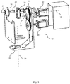
- FIG. 1 shows a perspective view of a hook winding machine 1 according to an embodiment of the present invention.
- the hook winding machine 1 comprises inter alia an automatic core feeding device 37, a core holding device 10, a wire feeding device 33, a display and input unit 40 as well as a hook mechanism 11 and a wire bending device 13 to be discussed below in further detail. All components and subsystems of the hook winding machine 1 are arranged on a common worktable and/or attached to a common frame of the hook winding machine 1.
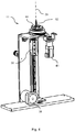
- the wire bending device 13 is shown in further detail in figures 2 and 3 . It comprises a rotatable arm 14 that is rotatable about a first rotation axis 15 and that is driven by a rotating drive 42 shown in the exploded view in figure 3 .
- the rotatable arm 14 comprises an eccentric shaft 22 arranged eccentrically with respect to and parallel to the first rotation axis 15.
- the eccentric shaft 22 is slidably supported in another component of the rotatable arm such that the eccentric shaft 22 can be shifted along its longitudinal direction.
- the eccentric shaft 22 carries a pulley 16 forming a wire grabbing portion of the rotatable arm 14.
- a cam disk 19 is rotatably supported concentrically to the first rotation axis 15 of the rotatable arm.
- the cam disc 19 is driven via a spur gear by a drive 20.
- a cam surface of the cam disc 19 is in contact with the second end 24 of the eccentric shaft 22 such that rotation of the cam disc 19 causes an axial displacement of the eccentric shaft 22 and the pulley 16 at the eccentric shaft's first end along the longitudinal direction of the eccentric shaft which corresponds to a retracting direction 21 parallel to the first rotation axis 15.
- the pulley 16 comprises two pulley halves 25 and 26 that are pre-tensioned against each other by a pre-tensioning spring 27 acting between the second pulley half 26 and an axial stop surface of the eccentric shaft 22.
- the pulley halves taper towards each other.
- the second pulley half 26 is bigger in diameter and axial length than the first pulley half 25.
- FIG 4 shows a detailed view of the hook mechanism 11 of the hook winding machine 1 shown in figure 1 .
- the hook winding mechanism comprises a longitudinally driven hook 12 connected to the slider 38 of a belt drive driven by hook mechanism drive 39. It should be mentioned that other types of drive for actuating the hook mechanism are generally possible.
- the hook mechanism may, for example, comprise a pneumatic cylinder instead of the belt drive shown in figure 4 .
- the hook mechanism 11 can be rotated with respect to the stationary frame of the hook winding machine around a second rotation axis 29 by the rotating unit 41.
- a connecting flange 43 of the wire bending device 13 shown in figures 2 and 3 is firmly connected to a connecting flange 44 of the hook mechanism 11 such that the wire bending device 13 rotates together with the hook mechanism 11 around the second rotation axis 29.
- FIG. 5 shows the core holding device 10 holding the toroidal core 4 in a position ready for the winding process.
- the toroidal core 4 has a through hole 5, and axis 6 defined by said through hole, an outer periphery 7, a first side 8 defined by a first axial end face of the core and a second side 9 opposite said first side 8 and defined by a second axial end face of the core.
- the wire feeding device 33 which is only schematically shown in figure 5 , automatically moves over the toroidal core 4 and feeds a first portion 35 of a used length 34 of wire 3 required for the coil from the first side 8 of the core 4 through the through hole 5 of the core 4.
- the wire feeding device then moves in a direction perpendicular to the axis 6 of the core 4 in order to hold a second portion 36 of the used length 34 of wire 3, which remains at the first side 8 of the core 4, eccentrically with respect to the axis 6 of the core 4.
- the wire 3 is then bent back by the wire bending mechanism 13 from the second side 9 of the core 4 over the outer periphery 7 of the core 4 to the first side 8 of the core 4.
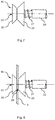
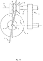
- the rotatable arm 14 of the wire bending device 13 rotates around the first rotation axis 15 by a rotation angle ⁇ in a first rotation direction 17 such that the pulley 16 moves from position A in which no contact between pulley 16 and wire 3 exists over position B in which the wire 3 is grabbed by the pulley 16 to position C.
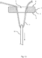
- the hook mechanism 11 moves the hook 12 upwards to a fully extended position as shown in figures 9, 10 and 11 .
- a special shape of the hook 12 as well as a certain flexibility of the hook 12 thereby allow the head of the hook 12 to slide past the wire 3.
- the pulley 16 is brought into its retracted position again and the wire bending device 13 is rotated together with the hook mechanism 11, as shown in figure 14 , around the core 4 by an advancing angle ⁇ about the second rotation axis 29 which coincides with the axis 6 of the toroidal core 4.
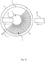
- the pulling and bending steps are repeated such that a coil 2 is finally wound onto a sector 32 of the toroidal core 4 as shown in figure 15 .
- the hook winding machine 1 may comprise a second core holding device 30 that takes over after a portion of the coil has been wound onto sector 32.
- the second core holding device 30 is adapted to hold the already wound sector 32 such that the first core holding device 10 can be retracted and another portion of the coil can be wound onto the sector 31 of the core 4. In this manner, it is possible to wind a coil that covers 360° of the toroidal core 4.
- the hook winding machine 1 further comprises a cutting unit for cutting the wire 3 after the winding process has been finished and an automatic discharge unit for discharging completed products such that the hook winding machine 1 is fully-automatically operable without any operator's assistance.
- the hook winding machine may, for example, comprise several core holding devices that are arranged on a holding device revolver in order to speed up the production process. It is also conceivable that the hook winding machine comprises several wire bending devices and hook mechanisms such that two or more coils can be wound at the same time.
Landscapes
- Engineering & Computer Science (AREA)
- Power Engineering (AREA)
- Manufacturing & Machinery (AREA)
- Manufacturing Cores, Coils, And Magnets (AREA)
Priority Applications (1)
| Application Number | Priority Date | Filing Date | Title |
|---|---|---|---|
| EP18200393.9A EP3640962A1 (de) | 2018-10-15 | 2018-10-15 | Automatische hakennadel-wickelmaschine |
Applications Claiming Priority (1)
| Application Number | Priority Date | Filing Date | Title |
|---|---|---|---|
| EP18200393.9A EP3640962A1 (de) | 2018-10-15 | 2018-10-15 | Automatische hakennadel-wickelmaschine |
Publications (1)
| Publication Number | Publication Date |
|---|---|
| EP3640962A1 true EP3640962A1 (de) | 2020-04-22 |
Family
ID=63857814
Family Applications (1)
| Application Number | Title | Priority Date | Filing Date |
|---|---|---|---|
| EP18200393.9A Withdrawn EP3640962A1 (de) | 2018-10-15 | 2018-10-15 | Automatische hakennadel-wickelmaschine |
Country Status (1)
| Country | Link |
|---|---|
| EP (1) | EP3640962A1 (de) |
Cited By (4)
| Publication number | Priority date | Publication date | Assignee | Title |
|---|---|---|---|---|
| CN113674990A (zh) * | 2021-08-27 | 2021-11-19 | 中山市科彼特自动化设备有限公司 | 钩针式电感绕线机用绕线装置 |
| CN113823505A (zh) * | 2021-08-27 | 2021-12-21 | 中山市科彼特自动化设备有限公司 | 钩针式电感绕线机 |
| CN114334432A (zh) * | 2022-01-26 | 2022-04-12 | 深圳市星特科技有限公司 | 一种全自动卡爪式多绕组磁环绕线机 |
| CN116864306A (zh) * | 2023-08-15 | 2023-10-10 | 中山市科彼特自动化设备有限公司 | 一种电感绕线方法 |
Citations (5)
| Publication number | Priority date | Publication date | Assignee | Title |
|---|---|---|---|---|
| CH353810A (de) * | 1956-03-23 | 1961-04-30 | Standard Telephon & Radio Ag | Verfahren zum Bewickeln eines Ringkerns |
| US3601731A (en) * | 1970-01-30 | 1971-08-24 | Ibm | Coil form for a magnetic deflection york |
| JPH03276607A (ja) * | 1990-03-26 | 1991-12-06 | Suzuki Kikai Kk | トロイダルコアの巻線装置 |
| JPH11238643A (ja) * | 1998-02-18 | 1999-08-31 | Tokin Corp | トロイダルコイル巻線機 |
| JP2015050254A (ja) * | 2013-08-30 | 2015-03-16 | 株式会社多賀製作所 | トロイダル巻線装置 |
-
2018
- 2018-10-15 EP EP18200393.9A patent/EP3640962A1/de not_active Withdrawn
Patent Citations (5)
| Publication number | Priority date | Publication date | Assignee | Title |
|---|---|---|---|---|
| CH353810A (de) * | 1956-03-23 | 1961-04-30 | Standard Telephon & Radio Ag | Verfahren zum Bewickeln eines Ringkerns |
| US3601731A (en) * | 1970-01-30 | 1971-08-24 | Ibm | Coil form for a magnetic deflection york |
| JPH03276607A (ja) * | 1990-03-26 | 1991-12-06 | Suzuki Kikai Kk | トロイダルコアの巻線装置 |
| JPH11238643A (ja) * | 1998-02-18 | 1999-08-31 | Tokin Corp | トロイダルコイル巻線機 |
| JP2015050254A (ja) * | 2013-08-30 | 2015-03-16 | 株式会社多賀製作所 | トロイダル巻線装置 |
Cited By (4)
| Publication number | Priority date | Publication date | Assignee | Title |
|---|---|---|---|---|
| CN113674990A (zh) * | 2021-08-27 | 2021-11-19 | 中山市科彼特自动化设备有限公司 | 钩针式电感绕线机用绕线装置 |
| CN113823505A (zh) * | 2021-08-27 | 2021-12-21 | 中山市科彼特自动化设备有限公司 | 钩针式电感绕线机 |
| CN114334432A (zh) * | 2022-01-26 | 2022-04-12 | 深圳市星特科技有限公司 | 一种全自动卡爪式多绕组磁环绕线机 |
| CN116864306A (zh) * | 2023-08-15 | 2023-10-10 | 中山市科彼特自动化设备有限公司 | 一种电感绕线方法 |
Similar Documents
| Publication | Publication Date | Title |
|---|---|---|
| EP3640962A1 (de) | Automatische hakennadel-wickelmaschine | |
| EP0916610B1 (de) | Aufwickelvorrichtung | |
| EP0916612B1 (de) | Vorrichtung und Verfahren zum Führen und Schneiden eines kontinuierlich zulaufenden Fadens | |
| EP2062274B1 (de) | Wickelvorrichtung und verfahren zum wickeln | |
| US4292114A (en) | Apparatus for coiling wire | |
| US3620482A (en) | Separator for unprocessed wire in reeling and winding apparatus | |
| JP3194520B2 (ja) | 巻線装置 | |
| US4028920A (en) | Apparatus for high speed winding of coils | |
| TW201238878A (en) | Winding machine | |
| US9808951B2 (en) | Scrap winder | |
| US5335868A (en) | Wire winding and connecting apparatus for armature and commutator | |
| KR101946099B1 (ko) | 비드링 결속사 권취 장치 | |
| US3672409A (en) | Wire coiling apparatus | |
| US4267865A (en) | Apparatus for producing coils | |
| DE2643421B2 (de) | Verfahren und Vorrichtung zum Übertragen eines Fadens in einer automatischen Spulmaschine | |
| US11878895B2 (en) | Cable coiling system | |
| US4214466A (en) | Apparatus for the winding of helical springs | |
| DE2729303C3 (de) | Verfahren zum kontinuierlichen Aufspulen von Draht oder anderem fadenförmigem Gut und Spulapparat hierfür | |
| CN100402172C (zh) | 用于轧制或拉制长产品的盘绕方法和设备 | |
| DE60006027T2 (de) | Maschine zum Wiederaufwickeln von Drahtbunden mit dicht aneinanderliegenden Windungen | |
| CN223606805U (zh) | 一种用于扁线阿尔法绕线的存线机构 | |
| US4787565A (en) | Method and assembly for forming thread reserve on spool tube in thread winding apparatus | |
| US3804347A (en) | Wire coiling apparatus | |
| CN219503476U (zh) | 一种焊锡丝机用盘线装置 | |
| JPS59150616A (ja) | ワイヤコイル生産システム |
Legal Events
| Date | Code | Title | Description |
|---|---|---|---|
| PUAI | Public reference made under article 153(3) epc to a published international application that has entered the european phase |
Free format text: ORIGINAL CODE: 0009012 |
|
| STAA | Information on the status of an ep patent application or granted ep patent |
Free format text: STATUS: THE APPLICATION HAS BEEN PUBLISHED |
|
| AK | Designated contracting states |
Kind code of ref document: A1 Designated state(s): AL AT BE BG CH CY CZ DE DK EE ES FI FR GB GR HR HU IE IS IT LI LT LU LV MC MK MT NL NO PL PT RO RS SE SI SK SM TR |
|
| AX | Request for extension of the european patent |
Extension state: BA ME |
|
| STAA | Information on the status of an ep patent application or granted ep patent |
Free format text: STATUS: REQUEST FOR EXAMINATION WAS MADE |
|
| 17P | Request for examination filed |
Effective date: 20201022 |
|
| RBV | Designated contracting states (corrected) |
Designated state(s): AL AT BE BG CH CY CZ DE DK EE ES FI FR GB GR HR HU IE IS IT LI LT LU LV MC MK MT NL NO PL PT RO RS SE SI SK SM TR |
|
| STAA | Information on the status of an ep patent application or granted ep patent |
Free format text: STATUS: THE APPLICATION IS DEEMED TO BE WITHDRAWN |
|
| 18D | Application deemed to be withdrawn |
Effective date: 20210501 |