EP3647578A1 - Statoréacteur à combustion supersonique et objet volant associé - Google Patents
Statoréacteur à combustion supersonique et objet volant associé Download PDFInfo
- Publication number
- EP3647578A1 EP3647578A1 EP18905558.5A EP18905558A EP3647578A1 EP 3647578 A1 EP3647578 A1 EP 3647578A1 EP 18905558 A EP18905558 A EP 18905558A EP 3647578 A1 EP3647578 A1 EP 3647578A1
- Authority
- EP
- European Patent Office
- Prior art keywords
- flow path
- forming member
- path forming
- cavity
- region
- Prior art date
- Legal status (The legal status is an assumption and is not a legal conclusion. Google has not performed a legal analysis and makes no representation as to the accuracy of the status listed.)
- Granted
Links
Images

Classifications
-
- F—MECHANICAL ENGINEERING; LIGHTING; HEATING; WEAPONS; BLASTING
- F02—COMBUSTION ENGINES; HOT-GAS OR COMBUSTION-PRODUCT ENGINE PLANTS
- F02K—JET-PROPULSION PLANTS
- F02K7/00—Plants in which the working fluid is used in a jet only, i.e. the plants not having a turbine or other engine driving a compressor or a ducted fan; Control thereof
- F02K7/10—Plants in which the working fluid is used in a jet only, i.e. the plants not having a turbine or other engine driving a compressor or a ducted fan; Control thereof characterised by having ram-action compression, i.e. aero-thermo-dynamic-ducts or ram-jet engines
- F02K7/14—Plants in which the working fluid is used in a jet only, i.e. the plants not having a turbine or other engine driving a compressor or a ducted fan; Control thereof characterised by having ram-action compression, i.e. aero-thermo-dynamic-ducts or ram-jet engines with external combustion, e.g. scram-jet engines
-
- F—MECHANICAL ENGINEERING; LIGHTING; HEATING; WEAPONS; BLASTING
- F05—INDEXING SCHEMES RELATING TO ENGINES OR PUMPS IN VARIOUS SUBCLASSES OF CLASSES F01-F04
- F05D—INDEXING SCHEME FOR ASPECTS RELATING TO NON-POSITIVE-DISPLACEMENT MACHINES OR ENGINES, GAS-TURBINES OR JET-PROPULSION PLANTS
- F05D2220/00—Application
- F05D2220/10—Application in ram-jet engines or ram-jet driven vehicles
-
- F—MECHANICAL ENGINEERING; LIGHTING; HEATING; WEAPONS; BLASTING
- F05—INDEXING SCHEMES RELATING TO ENGINES OR PUMPS IN VARIOUS SUBCLASSES OF CLASSES F01-F04
- F05D—INDEXING SCHEME FOR ASPECTS RELATING TO NON-POSITIVE-DISPLACEMENT MACHINES OR ENGINES, GAS-TURBINES OR JET-PROPULSION PLANTS
- F05D2240/00—Components
- F05D2240/35—Combustors or associated equipment
Definitions
- the present invention relates to a scramjet engine and a flying object.
- a scramjet engine is considered as a propulsion device for a flying object that flies at supersonic speed.
- a scramjet engine is configured to obtain a thrust by: taking in and compressing with ram pressure supersonic air to generate compressed air; injecting fuel into the relevant compressed air to burn the fuel; and exhausting combustion gas of high temperature and high pressure generated by the burning.
- Japanese Patent Publication No. 2012-202226 discloses a scramjet engine with a variable fuel injection direction. This publication discloses a technology of injecting fuel from a ramp provided to a wall surface into airflow and a technology of injecting fuel from upstream of a cavity into airflow.
- Japanese Patent Publication No. 2004-84516 discloses a technology of providing a protrusion object with acute angle facing the rear on an engine inner wall and directing a recirculation flow from the rear to the rear by this protrusion object.
- An objective of the present invention is to improve combustion efficiency of a scramjet engine.
- Other objectives and new features of the present invention will be understood by skilled persons in the art from following descriptions.
- a scramjet engine is provided with a first flow path forming member, a second flow path forming member provided in opposite to the first flow path forming member, a first fuel injection device and a second fuel injection device.
- a flow path is formed between the first flow path forming member and the second flow path forming member.
- the flow path includes a turbulence formation region where a compressed air is introduced from upstream and a combustion region that is located downstream of the turbulence formation region and where a combustion using the compressed air is carried out.
- the second flow path forming member is formed with a protrusion located in the turbulence formation region and protruding toward the first flow path forming member.
- the first fuel injection device is configured to inject fuel into the compressed air via a first fuel nozzle provided to the protrusion.
- the second flow path forming member is formed with a cavity located in the combustion region.
- the second fuel injection device is configured to inject fuel into the compressed air via a second fuel nozzle provided to the cavity.
- the cavity is provided with a bottom surface and an inclined surface connected to a downstream side end of the bottom surface. An inclination of the inclined surface of the cavity is adjusted so that a shock wave is generated in the combustion region.
- the flow path may be further provided with an upstream region configured to introduce the compressed air to the turbulence forming region.
- an adjustment is carried out so that an angle between the inclined surface of the cavity and a first surface that is a surface of a part of the second flow path forming member facing the upstream region is less than or equal to 45 degrees.
- the angle between the inclined surface of the cavity and the first surface of the second flow path forming member is larger than or equal to 20 degrees.
- the second fuel injection device injects fuel from a location downstream of a discontinuity surface generated by a generation of the shock wave to a location upstream of the relevant discontinuity surface so that the fuel crosses the discontinuity surface.
- the second flow path forming member is provided with a second surface located downstream of the protrusion of the turbulence forming region and a distance between the second surface and the first flow path forming member is larger than a distance between the first surface and the first flow path forming member.
- a top end of a front wall of the cavity is connected to the second surface and an upstream side end of the bottom surface of the cavity is connected to a bottom end of the front wall.
- the scramjet engine is further provided with a third fuel injection device configured to inject fuel to the second flow path forming member via a third fuel nozzle provided to the first flow path forming member at a location downstream to the cavity.
- the above described scramjet engine may be provided to a flying object and used.
- a combustion efficiency of a scramjet engine can be improved.
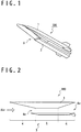
- Fig. 1 is a perspective view showing a configuration of a flying object 100 according to an embodiment.
- a fuselage 1 of the flying object 100 is provided with a cowl 2 and various members and equipments constituting a scramjet engine 3 are provided to the fuselage 1 and the cowl 2.
- the scramjet engine 3 is schematically provided with an inlet section 4, a combustor 5 and a nozzle section 6.
- the inlet section 4 take in supersonic air from a front opening 4a, compresses the air that is taken in and generates compressed air.
- the combustor 5 receives the compressed air from the inlet section 4, combusts fuel by use of the relevant compressed air and generates combustion gas.
- the nozzle section 6 exhausts the combustion gas generated in the combustor 5 from a rear opening 6a. Propulsion of the flying object 100 can be obtained by exhausting combustion gas from the rear opening 6a.
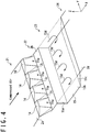
- Fig. 3 is a cross sectional view showing a configuration of a combustor 5. It should be noted that in the following description an XYZ Cartesian coordinate system will be introduced and directions may be expressed by use of the relevant XYZ Cartesian coordinate system.
- the combustor 5 is provided with fuel injection devices 11, 12 provided to the cowl 2 and a fuel injection device 13 provided to the fuselage 1, and is configured to inject fuel by the fuel injection devices 11, 12, 13 into the compressed air received from the inlet section 4 and combust the fuel.
- a space between the fuselage 1 and the cowl 2 is used as a flow path 20 of the combustor 5. That is, the fuselage 1 and the cowl 2 are used as flow path forming members that form the flow path 20.
- the flow path 20 of the combustor 5 includes an upstream region 21, a turbulence forming region 22, a combustion region 23 and a downstream region 24.
- the upstream region 21 is formed between a surface 1a of the fuselage 1 and a surface 2a (a first surface) of the cowl 2 and introduces the compressed air generated in the inlet section 4 to the turbulence forming region 22.
- the surface 2a is located at the uppermost stream of the combustor 5 and regulates a direction of a flow of the compressed air and the combustion gas in the whole combustor 5.
- the direction of the flow of the compressed air and the combustion gas in the whole combustor 5 is +X direction and the surface 1a of the fuselage 1 and the surface 2a of the cowl 2 are parallel to XZ plane.
- a height of the flow path in the upstream region 21, that is, a distance between the surface 1a of the fuselage 1 and the surface 2a of the cowl 2, is H 1 .
- the turbulence forming region 22 is located downstream of the upstream region 21.
- a protrusion 14 protruding toward the surface 1a of the fuselage 1 is formed in a part of the cowl 2 facing the turbulence forming region 22.
- a plurality of protrusions 14 are arranged along a direction of crossing the flow path 20, that is, in Y axis direction.
- the protrusions 14 form turbulence in downstream thereof.
- the turbulence formed downstream of the protrusions 14 contributes to improvement of combustion efficiency.
- Fuel nozzles 11a are formed in protrusions 14 and the fuel injection device 11 injects fuel from the fuel nozzles 11a to downstream of the protrusions 14. As a result, the fuel is injected into a turbulence generated by the protrusions 14.
- the surface 2b (second surface) of the cowl 2 is connected to a downstream side end of the protrusion 14.
- the surface 2b is in parallel with XZ plane.
- a height of the flow path 20 at the surface 2b of the cowl 2, that is, a distance between the surface 1a of the fuselage 1 and the surface 2b of the cowl 2 is H 2 .
- the height H 2 of the flow path 20 at the surface 2b located downstream of the protrusions 14 is higher than the height H 1 of the flow path 20 at the surface 2a located upstream of the protrusions 14.
- the surface 2a located upstream of the protrusions 14 and the surface 2b located downstream of the protrusions 14 are connected by surfaces 2c of the cowl 2 formed between adjacent protrusions 14.
- the combustion region 23 is located downstream of the turbulence forming region 22 and in the combustion region 23 an air-fuel mixture that is formed is ignited and the air-fuel mixture is combusted. It should be noted that the combustion region 23 means a region where the combustion is mainly carried out but does not mean that combustion does not occur in any other region. For example, combustion may occur in a part of the downstream region 24 too.
- a cavity 15 is formed in a part of the cowl 2 facing the combustion region 23 for flame holding.
- the cavity 15 is formed to be recessed from the surface 2b located downstream of the protrusions 14 and has a front wall 15a, a bottom surface 15b and an inclined surface 15c.
- a top end of the front wall 15a is located adjacent to the turbulence forming region 22 and is connected to a downstream side end of the surface 2b.
- the front wall 15a is perpendicular to the surface 2b (that is, parallel to YZ plane).
- the bottom surface 15b is connected to a bottom end of the front wall 15a.
- the bottom surface 15b of the cavity 15 is parallel to the surface 2a of the cowl 2 facing the upstream region 21 (that is, parallel to XZ plane).
- the inclined surface 15c of the cavity 15 is connected to a downstream side end of the bottom surface 15b.
- the inclined surface 15c of the cavity 15 is inclined so that an angle between the inclined surface 15c and the surface 2a is angle ⁇ 1 (that is, an angle between the inclined surface 15c and XZ plane is angle ⁇ 1 ).
- the angle ⁇ 1 may be called cavity ramp angle.
- the inclined surface 15c is inclined so that an angle between the inclined surface 15c and the bottom surface 15b is angle ⁇ 1 .
- Fuel nozzles 12a are formed at inclined surfaces 15c of the cavity 15 and the fuel injection devices 12 inject fuel from fuel nozzles 12a to inside the cavity 15. Furthermore, an ignition device 16 that ignites fuel injected to the cavity 15 is provided at the bottom surface 15b of the cavity 15.
- the downstream region 24 is located downstream of the combustion region 23.
- the downstream region 24 feeds the combustion gas generated by combustion in the combustor 5 into the nozzle section 6.
- a fuel nozzle 13a is provided at a part of the surface 1a of the fuselage 1 facing the downstream region 24 and the fuel injection device 13 injects fuel from the fuel nozzle 13a to the downstream region 24.
- the fuel injection device 13 is provided in order to block a flow of the combustion gas by injecting fuel in the downstream region 24 and thereby promoting combustion.
- a cross-sectional area of the flow path 20 may increase toward the downstream.
- Such configuration contributes to flow the combustion gas downstream along the cowl 2 smoothly in the downstream region 24.
- the scramjet engine 3 according to the present embodiment becomes unable to take in air when the flow of the combustion gas is excessively blocked by injection of fuel by the fuel injection device 13 because an upstream pressure becomes excessively high.
- an opening angle is set to the cowl 2 in the downstream region 24. That is, the surface 2d of the cowl 2 facing the downstream region 24 is inclined so that a distance between the surface 1a of the fuselage 1 and the surface 2d of the cowl 2 increase toward downstream.
- a symbol ⁇ 2 an angle between the surface 1a of the fuselage 1 and the surface 2d of the cowl 2 is shown by a symbol ⁇ 2 .
- the angle ⁇ 2 may be set larger than or equal to 2 degrees and less than or equal to 4 degrees.
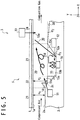
- Fig. 5 is a diagram showing an operation of the combustor 5 according to the present embodiment.
- the inclination of the inclined surface 15c of the cavity 15 is adjusted so that a shock wave is generate in the combustion region 23, and as a result a combustion efficiency is improved.
- a generation of a shock wave means that a pressure discontinuity surface 30 is generated.
- the discontinuity surface 30 is oblique to the flow of combustion gas, that is, an oblique shock wave is generated.
- the cavity 15 is a structure configured to form a circulation flow inside by slowing a flow of an air-fuel mixture and realize flame holding by igniting this circulation flow. From such a point of view, it is common to set a relatively large value to the cavity ramp angle, that is, the angle ⁇ 1 between the inclined surface 15c and the surface 2a of the cowl 2, in order to slow enough the flow of the air-fuel mixture.
- the inventor discovered that when an inclination of the inclined surface 15c of the cavity 15 is gentle, that is, when the angle ⁇ 1 between the inclined surface 15c and the surface 2a of the cowl 2 is smaller, an action of slowing a flow inside the cavity 15 is weaker, rather the combustion is promoted by generation of a shock wave.
- a shock wave is generated in the combustion region 23
- a pressure discontinuity surface 30 is formed in the combustion region 23. In a vicinity region in upstream side of the discontinuity surface 30, pressure and temperature increase and by carrying out combustion in such a region, combustion efficiency can be effectively improved.
- the angle ⁇ 1 between the inclined surface 15c of the cavity 15 and the surface 2a of the cowl 2 is larger than or equal to 20 degrees.
- the compressed air generated by the inlet section 4 flows into the upstream region 21 and further is introduced to the turbulence forming region 22.
- the structure of the turbulence forming region 22 of the combustor 5 according to the present embodiment further improves efficiency of forming air-fuel mixture.
- the height H 2 of the flow path 20 at the surface 2b located downstream of the protrusions 14 is higher than the height H 1 of the flow path 20 at the surface 2a located upstream of the protrusions 14, and the pressure at a part that faces the surface 2b of the turbulence forming region 22 becomes lower than in the upstream region 21.
- the surface 2a located upstream of the protrusions 14 and the surface 2b located downstream of the protrusions 14 are connected by the surfaces 2c of the cowl 2 formed between adjacent protrusions 14, and a flow of compressed air is formed between adjacent protrusions 14 and along the surfaces 2c.
- forming of turbulence is promoted and air-fuel mixture in that fuel and compressed air are mixed is efficiently generated.
- the air-fuel mixture generated in the turbulence forming region 22 is introduced to the combustion region 23.
- a part of the air-fuel mixture is decelerated by the cavity 15 and as a result a circulation flow 15d is formed in the cavity 15.
- flame is hold in the cavity 15.
- the air-fuel mixture introduced to the combustion region 23 is ignited by the flame hold in the cavity 15, the air-fuel mixture burns and the combustion gas is generated.
- shock wave is generated in the combustion region 23 because of a gentle formation of the inclined surface 15c of the cavity 15, and as a result a pressure discontinuity surface 30 is formed in the combustion region 23.
- a pressure discontinuity surface 30 is formed in the combustion region 23.
- high combustion efficiency is obtained because pressure and temperature increase.
- the discontinuity surface 30 reaches inside the cavity 15, and the fuel injection device 12 injects fuel from a location downstream of the discontinuity surface 30 to a location upstream of the discontinuity surface 30 so that the fuel crosses the discontinuity surface 30. This is effective to promote mixing of circulation flow 15d generated inside the cavity 15 and the fuel and to improve combustion efficiency.
- the combustion gas generated in the combustion region 23 is introduced to the downstream region 24.
- the flow of the combustion gas flown from the combustion region 23 is blocked by the fuel injection of the fuel injection device 13 and a speed of the combustion gas is decreased.
- combustion of unburned fuel included in the combustion gas can be promoted.
- the combustion gas is introduced from the downstream region 24 to the nozzle section 6 and exhausted from the nozzle section 6. As a result, propulsion to propel the flying object 100 can be obtained.
- the scramjet engine 3 can improve combustion efficiency of combustion gas by generating shock wave in the combustion region 23.
- the fuel injection device 13 is provided to the fuselage 1 and the fuel injection devices 11, 12, the protrusions 14, the cavity 15 and the ignition device 16 are on the cowl 2
- the present invention is not limited to this.
- the components that are described in the above described embodiment to be provided to the cowl 2 may be provided to the fuselage 1 and the components that are described to be provided to the fuselage 1 may be provided to the cowl 2.
- the fuel injection device 13 that injects fuel into the downstream region 24 may be omitted.
Landscapes
- Engineering & Computer Science (AREA)
- Chemical & Material Sciences (AREA)
- Combustion & Propulsion (AREA)
- Mechanical Engineering (AREA)
- General Engineering & Computer Science (AREA)
- Combustion Methods Of Internal-Combustion Engines (AREA)
Applications Claiming Priority (2)
| Application Number | Priority Date | Filing Date | Title |
|---|---|---|---|
| JP2018022332A JP7001489B2 (ja) | 2018-02-09 | 2018-02-09 | スクラムジェットエンジン及び飛翔体 |
| PCT/JP2018/026500 WO2019155654A1 (fr) | 2018-02-09 | 2018-07-13 | Statoréacteur à combustion supersonique et objet volant associé |
Publications (3)
| Publication Number | Publication Date |
|---|---|
| EP3647578A1 true EP3647578A1 (fr) | 2020-05-06 |
| EP3647578A4 EP3647578A4 (fr) | 2020-07-22 |
| EP3647578B1 EP3647578B1 (fr) | 2024-02-14 |
Family
ID=67548352
Family Applications (1)
| Application Number | Title | Priority Date | Filing Date |
|---|---|---|---|
| EP18905558.5A Active EP3647578B1 (fr) | 2018-02-09 | 2018-07-13 | Statoréacteur à combustion supersonique et objet volant associé |
Country Status (5)
| Country | Link |
|---|---|
| US (1) | US11692514B2 (fr) |
| EP (1) | EP3647578B1 (fr) |
| JP (1) | JP7001489B2 (fr) |
| AU (1) | AU2018407616B2 (fr) |
| WO (1) | WO2019155654A1 (fr) |
Families Citing this family (2)
| Publication number | Priority date | Publication date | Assignee | Title |
|---|---|---|---|---|
| US11415080B2 (en) * | 2018-05-14 | 2022-08-16 | General Electric Company | Engine for an aircraft |
| CN111664023A (zh) * | 2020-07-03 | 2020-09-15 | 中国空气动力研究与发展中心 | 一种超燃冲压发动机的燃料掺混装置 |
Family Cites Families (31)
| Publication number | Priority date | Publication date | Assignee | Title |
|---|---|---|---|---|
| US2952123A (en) * | 1956-05-25 | 1960-09-13 | Lockheed Aircraft Corp | Directional controls for propulsive jets |
| JPH0715264B2 (ja) * | 1989-01-31 | 1995-02-22 | 日産自動車株式会社 | 超音速空気取入装置 |
| US5072581A (en) * | 1989-03-23 | 1991-12-17 | General Electric Company | Scramjet combustor |
| US5109670A (en) * | 1989-03-23 | 1992-05-05 | General Electric Company | Scramjet combustor |
| US5072582A (en) | 1989-03-23 | 1991-12-17 | General Electric Company | Scramjet combustor |
| US5202525A (en) | 1990-01-29 | 1993-04-13 | General Electric Company | Scramjet engine having improved fuel/air mixing |
| US5058826A (en) | 1990-01-29 | 1991-10-22 | General Electric Company | Scramjet engine having a low pressure combustion cycle |
| US5085048A (en) | 1990-02-28 | 1992-02-04 | General Electric Company | Scramjet including integrated inlet and combustor |
| US5253474A (en) * | 1991-08-30 | 1993-10-19 | General Electric Company | Apparatus for supersonic combustion in a restricted length |
| US5791148A (en) * | 1995-06-07 | 1998-08-11 | General Electric Company | Liner of a gas turbine engine combustor having trapped vortex cavity |
| JPH08334213A (ja) * | 1995-06-09 | 1996-12-17 | Ishikawajima Harima Heavy Ind Co Ltd | 超音速燃焼器とその着火方法 |
| EP0999367B1 (fr) * | 1998-11-06 | 2003-02-12 | ALSTOM (Switzerland) Ltd | Conduit d'écoulement à discontinuité de section transversale |
| US6286298B1 (en) * | 1998-12-18 | 2001-09-11 | General Electric Company | Apparatus and method for rich-quench-lean (RQL) concept in a gas turbine engine combustor having trapped vortex cavity |
| US6786040B2 (en) | 2002-02-20 | 2004-09-07 | Space Access, Llc | Ejector based engines |
| JP3994122B2 (ja) * | 2002-08-26 | 2007-10-17 | 独立行政法人科学技術振興機構 | 境界層剥離制御装置と燃料噴射器および制御方法 |
| US20080196414A1 (en) | 2005-03-22 | 2008-08-21 | Andreadis Dean E | Strut cavity pilot and fuel injector assembly |
| US20080060361A1 (en) * | 2006-09-07 | 2008-03-13 | Pratt & Whitney Rocketdyne, Inc. | Multi-height ramp injector scramjet combustor |
| KR20090055412A (ko) * | 2007-11-28 | 2009-06-02 | 재단법인서울대학교산학협력재단 | 초음속 유동장 내 공동을 이용한 연료-공기 혼합 구조 |
| US8484980B1 (en) | 2009-11-19 | 2013-07-16 | The United States Of America As Represented By The Administrator Of National Aeronautics And Space Administration | Dual-mode combustor |
| KR101046759B1 (ko) * | 2009-12-22 | 2011-07-06 | 한국항공우주연구원 | 스크램제트엔진 연소기용 연소증진보염기 |
| JP5529651B2 (ja) | 2010-07-01 | 2014-06-25 | 三菱重工業株式会社 | 超音速燃焼器の着火方法及び着火制御装置 |
| JP5529650B2 (ja) | 2010-07-01 | 2014-06-25 | 三菱重工業株式会社 | 超音速燃焼器 |
| JP5758160B2 (ja) * | 2011-03-23 | 2015-08-05 | 三菱重工業株式会社 | スクラムジェットエンジン |
| JP5791323B2 (ja) | 2011-03-29 | 2015-10-07 | 三菱重工業株式会社 | スクラムジェットエンジン |
| JP2016056692A (ja) * | 2014-09-05 | 2016-04-21 | 国立大学法人東北大学 | スクラムジェットエンジン用燃焼装置及びスクラムジェットエンジン |
| JP6441695B2 (ja) | 2015-01-28 | 2018-12-19 | 三菱重工業株式会社 | ジェットエンジン、飛しょう体及びジェットエンジンの動作方法 |
| JP6688637B2 (ja) | 2016-03-10 | 2020-04-28 | 三菱重工業株式会社 | スクラムジェットエンジン、飛翔体 |
| JP2017166409A (ja) | 2016-03-16 | 2017-09-21 | 三菱重工業株式会社 | ジェットエンジン、および、飛しょう体 |
| JP6719933B2 (ja) | 2016-03-16 | 2020-07-08 | 三菱重工業株式会社 | ジェットエンジン、飛しょう体、および、ジェットエンジンの動作方法 |
| JP6628246B2 (ja) | 2016-03-28 | 2020-01-08 | 三菱重工業株式会社 | スクラムジェットエンジン、飛しょう体 |
| JP7054603B2 (ja) | 2016-08-03 | 2022-04-14 | ヤフー株式会社 | 判定装置、判定方法、及び判定プログラム |
-
2018
- 2018-02-09 JP JP2018022332A patent/JP7001489B2/ja active Active
- 2018-07-13 US US16/638,203 patent/US11692514B2/en active Active
- 2018-07-13 AU AU2018407616A patent/AU2018407616B2/en active Active
- 2018-07-13 WO PCT/JP2018/026500 patent/WO2019155654A1/fr not_active Ceased
- 2018-07-13 EP EP18905558.5A patent/EP3647578B1/fr active Active
Also Published As
| Publication number | Publication date |
|---|---|
| EP3647578B1 (fr) | 2024-02-14 |
| JP2019138219A (ja) | 2019-08-22 |
| WO2019155654A1 (fr) | 2019-08-15 |
| EP3647578A4 (fr) | 2020-07-22 |
| AU2018407616B2 (en) | 2021-05-20 |
| US20200362795A1 (en) | 2020-11-19 |
| US11692514B2 (en) | 2023-07-04 |
| AU2018407616A1 (en) | 2020-02-27 |
| JP7001489B2 (ja) | 2022-01-19 |
Similar Documents
| Publication | Publication Date | Title |
|---|---|---|
| JP2012117806A (ja) | 保炎抵抗を向上させる予混合器後流及び渦補填システム及び方法 | |
| AU2018407616B2 (en) | Scramjet engine and flying object | |
| US10830439B2 (en) | Jet engine, flying object, and method of operating a jet engine | |
| KR101954034B1 (ko) | 초음속 연료 분사 장치 | |
| US20230133001A1 (en) | System and method for ram air intake for pulse combustors | |
| JP2015183680A (ja) | 燃焼器、ジェットエンジン、飛しょう体及びジェットエンジンの動作方法 | |
| US11215144B2 (en) | Scramjet engine | |
| JP2017160873A (ja) | スクラムジェットエンジン、飛翔体 | |
| US11002225B1 (en) | Air-breathing rocket engine | |
| EP3339738A1 (fr) | Turbine comprenant une chambre de combustion de recirculation de gaz combustible | |
| RU2529935C1 (ru) | Гиперзвуковой прямоточный воздушно-реактивный двигатель и способ организации рабочего процесса | |
| JP3511075B2 (ja) | 低公害燃焼器およびその燃焼制御方法 | |
| JP6085472B2 (ja) | スクラムジェットエンジン及び燃焼制御方法 | |
| JPH08219408A (ja) | 超音速燃焼器 | |
| CN115263564A (zh) | 一种宽域冲压发动机推力突变的调控方法 | |
| US11174817B2 (en) | Air-Breathing rocket engine | |
| JPH06330765A (ja) | ジェットエンジンの保炎装置 | |
| JP3559867B2 (ja) | ラムジェット・エンジン用燃焼装置 | |
| JP2712830B2 (ja) | 混合燃焼器 | |
| JP3042206B2 (ja) | スクラムジェットエンジン | |
| JP3185501B2 (ja) | ラム燃焼装置 | |
| JP2002061841A (ja) | 燃焼器、ガスタービンおよびジェットエンジン | |
| JPH07279759A (ja) | ラム燃焼装置 | |
| JPH0683931U (ja) | ジェットエンジンの着火装置 | |
| JPH06346793A (ja) | 超音速燃焼器と超音速気流の混合促進方法 |
Legal Events
| Date | Code | Title | Description |
|---|---|---|---|
| STAA | Information on the status of an ep patent application or granted ep patent |
Free format text: STATUS: THE INTERNATIONAL PUBLICATION HAS BEEN MADE |
|
| PUAI | Public reference made under article 153(3) epc to a published international application that has entered the european phase |
Free format text: ORIGINAL CODE: 0009012 |
|
| STAA | Information on the status of an ep patent application or granted ep patent |
Free format text: STATUS: REQUEST FOR EXAMINATION WAS MADE |
|
| 17P | Request for examination filed |
Effective date: 20200128 |
|
| AK | Designated contracting states |
Kind code of ref document: A1 Designated state(s): AL AT BE BG CH CY CZ DE DK EE ES FI FR GB GR HR HU IE IS IT LI LT LU LV MC MK MT NL NO PL PT RO RS SE SI SK SM TR |
|
| AX | Request for extension of the european patent |
Extension state: BA ME |
|
| A4 | Supplementary search report drawn up and despatched |
Effective date: 20200619 |
|
| RIC1 | Information provided on ipc code assigned before grant |
Ipc: F02K 7/14 20060101AFI20200615BHEP |
|
| DAV | Request for validation of the european patent (deleted) | ||
| DAX | Request for extension of the european patent (deleted) | ||
| STAA | Information on the status of an ep patent application or granted ep patent |
Free format text: STATUS: EXAMINATION IS IN PROGRESS |
|
| 17Q | First examination report despatched |
Effective date: 20220209 |
|
| GRAP | Despatch of communication of intention to grant a patent |
Free format text: ORIGINAL CODE: EPIDOSNIGR1 |
|
| STAA | Information on the status of an ep patent application or granted ep patent |
Free format text: STATUS: GRANT OF PATENT IS INTENDED |
|
| INTG | Intention to grant announced |
Effective date: 20230925 |
|
| GRAS | Grant fee paid |
Free format text: ORIGINAL CODE: EPIDOSNIGR3 |
|
| GRAA | (expected) grant |
Free format text: ORIGINAL CODE: 0009210 |
|
| STAA | Information on the status of an ep patent application or granted ep patent |
Free format text: STATUS: THE PATENT HAS BEEN GRANTED |
|
| AK | Designated contracting states |
Kind code of ref document: B1 Designated state(s): AL AT BE BG CH CY CZ DE DK EE ES FI FR GB GR HR HU IE IS IT LI LT LU LV MC MK MT NL NO PL PT RO RS SE SI SK SM TR |
|
| REG | Reference to a national code |
Ref country code: GB Ref legal event code: FG4D |
|
| REG | Reference to a national code |
Ref country code: CH Ref legal event code: EP |
|
| REG | Reference to a national code |
Ref country code: DE Ref legal event code: R096 Ref document number: 602018065374 Country of ref document: DE |
|
| REG | Reference to a national code |
Ref country code: IE Ref legal event code: FG4D |
|
| REG | Reference to a national code |
Ref country code: LT Ref legal event code: MG9D |
|
| REG | Reference to a national code |
Ref country code: NL Ref legal event code: MP Effective date: 20240214 |
|
| PG25 | Lapsed in a contracting state [announced via postgrant information from national office to epo] |
Ref country code: IS Free format text: LAPSE BECAUSE OF FAILURE TO SUBMIT A TRANSLATION OF THE DESCRIPTION OR TO PAY THE FEE WITHIN THE PRESCRIBED TIME-LIMIT Effective date: 20240614 |
|
| PG25 | Lapsed in a contracting state [announced via postgrant information from national office to epo] |
Ref country code: LT Free format text: LAPSE BECAUSE OF FAILURE TO SUBMIT A TRANSLATION OF THE DESCRIPTION OR TO PAY THE FEE WITHIN THE PRESCRIBED TIME-LIMIT Effective date: 20240214 |
|
| PG25 | Lapsed in a contracting state [announced via postgrant information from national office to epo] |
Ref country code: GR Free format text: LAPSE BECAUSE OF FAILURE TO SUBMIT A TRANSLATION OF THE DESCRIPTION OR TO PAY THE FEE WITHIN THE PRESCRIBED TIME-LIMIT Effective date: 20240515 |
|
| REG | Reference to a national code |
Ref country code: AT Ref legal event code: MK05 Ref document number: 1657201 Country of ref document: AT Kind code of ref document: T Effective date: 20240214 |
|
| PG25 | Lapsed in a contracting state [announced via postgrant information from national office to epo] |
Ref country code: HR Free format text: LAPSE BECAUSE OF FAILURE TO SUBMIT A TRANSLATION OF THE DESCRIPTION OR TO PAY THE FEE WITHIN THE PRESCRIBED TIME-LIMIT Effective date: 20240214 Ref country code: NL Free format text: LAPSE BECAUSE OF FAILURE TO SUBMIT A TRANSLATION OF THE DESCRIPTION OR TO PAY THE FEE WITHIN THE PRESCRIBED TIME-LIMIT Effective date: 20240214 Ref country code: RS Free format text: LAPSE BECAUSE OF FAILURE TO SUBMIT A TRANSLATION OF THE DESCRIPTION OR TO PAY THE FEE WITHIN THE PRESCRIBED TIME-LIMIT Effective date: 20240514 |
|
| PG25 | Lapsed in a contracting state [announced via postgrant information from national office to epo] |
Ref country code: ES Free format text: LAPSE BECAUSE OF FAILURE TO SUBMIT A TRANSLATION OF THE DESCRIPTION OR TO PAY THE FEE WITHIN THE PRESCRIBED TIME-LIMIT Effective date: 20240214 |
|
| PG25 | Lapsed in a contracting state [announced via postgrant information from national office to epo] |
Ref country code: AT Free format text: LAPSE BECAUSE OF FAILURE TO SUBMIT A TRANSLATION OF THE DESCRIPTION OR TO PAY THE FEE WITHIN THE PRESCRIBED TIME-LIMIT Effective date: 20240214 |
|
| PG25 | Lapsed in a contracting state [announced via postgrant information from national office to epo] |
Ref country code: RS Free format text: LAPSE BECAUSE OF FAILURE TO SUBMIT A TRANSLATION OF THE DESCRIPTION OR TO PAY THE FEE WITHIN THE PRESCRIBED TIME-LIMIT Effective date: 20240514 Ref country code: NO Free format text: LAPSE BECAUSE OF FAILURE TO SUBMIT A TRANSLATION OF THE DESCRIPTION OR TO PAY THE FEE WITHIN THE PRESCRIBED TIME-LIMIT Effective date: 20240514 Ref country code: NL Free format text: LAPSE BECAUSE OF FAILURE TO SUBMIT A TRANSLATION OF THE DESCRIPTION OR TO PAY THE FEE WITHIN THE PRESCRIBED TIME-LIMIT Effective date: 20240214 Ref country code: LT Free format text: LAPSE BECAUSE OF FAILURE TO SUBMIT A TRANSLATION OF THE DESCRIPTION OR TO PAY THE FEE WITHIN THE PRESCRIBED TIME-LIMIT Effective date: 20240214 Ref country code: IS Free format text: LAPSE BECAUSE OF FAILURE TO SUBMIT A TRANSLATION OF THE DESCRIPTION OR TO PAY THE FEE WITHIN THE PRESCRIBED TIME-LIMIT Effective date: 20240614 Ref country code: HR Free format text: LAPSE BECAUSE OF FAILURE TO SUBMIT A TRANSLATION OF THE DESCRIPTION OR TO PAY THE FEE WITHIN THE PRESCRIBED TIME-LIMIT Effective date: 20240214 Ref country code: GR Free format text: LAPSE BECAUSE OF FAILURE TO SUBMIT A TRANSLATION OF THE DESCRIPTION OR TO PAY THE FEE WITHIN THE PRESCRIBED TIME-LIMIT Effective date: 20240515 Ref country code: FI Free format text: LAPSE BECAUSE OF FAILURE TO SUBMIT A TRANSLATION OF THE DESCRIPTION OR TO PAY THE FEE WITHIN THE PRESCRIBED TIME-LIMIT Effective date: 20240214 Ref country code: ES Free format text: LAPSE BECAUSE OF FAILURE TO SUBMIT A TRANSLATION OF THE DESCRIPTION OR TO PAY THE FEE WITHIN THE PRESCRIBED TIME-LIMIT Effective date: 20240214 Ref country code: BG Free format text: LAPSE BECAUSE OF FAILURE TO SUBMIT A TRANSLATION OF THE DESCRIPTION OR TO PAY THE FEE WITHIN THE PRESCRIBED TIME-LIMIT Effective date: 20240214 Ref country code: AT Free format text: LAPSE BECAUSE OF FAILURE TO SUBMIT A TRANSLATION OF THE DESCRIPTION OR TO PAY THE FEE WITHIN THE PRESCRIBED TIME-LIMIT Effective date: 20240214 |
|
| PG25 | Lapsed in a contracting state [announced via postgrant information from national office to epo] |
Ref country code: PL Free format text: LAPSE BECAUSE OF FAILURE TO SUBMIT A TRANSLATION OF THE DESCRIPTION OR TO PAY THE FEE WITHIN THE PRESCRIBED TIME-LIMIT Effective date: 20240214 Ref country code: PT Free format text: LAPSE BECAUSE OF FAILURE TO SUBMIT A TRANSLATION OF THE DESCRIPTION OR TO PAY THE FEE WITHIN THE PRESCRIBED TIME-LIMIT Effective date: 20240614 |
|
| PG25 | Lapsed in a contracting state [announced via postgrant information from national office to epo] |
Ref country code: SE Free format text: LAPSE BECAUSE OF FAILURE TO SUBMIT A TRANSLATION OF THE DESCRIPTION OR TO PAY THE FEE WITHIN THE PRESCRIBED TIME-LIMIT Effective date: 20240214 Ref country code: PT Free format text: LAPSE BECAUSE OF FAILURE TO SUBMIT A TRANSLATION OF THE DESCRIPTION OR TO PAY THE FEE WITHIN THE PRESCRIBED TIME-LIMIT Effective date: 20240614 Ref country code: PL Free format text: LAPSE BECAUSE OF FAILURE TO SUBMIT A TRANSLATION OF THE DESCRIPTION OR TO PAY THE FEE WITHIN THE PRESCRIBED TIME-LIMIT Effective date: 20240214 Ref country code: LV Free format text: LAPSE BECAUSE OF FAILURE TO SUBMIT A TRANSLATION OF THE DESCRIPTION OR TO PAY THE FEE WITHIN THE PRESCRIBED TIME-LIMIT Effective date: 20240214 |
|
| PG25 | Lapsed in a contracting state [announced via postgrant information from national office to epo] |
Ref country code: DK Free format text: LAPSE BECAUSE OF FAILURE TO SUBMIT A TRANSLATION OF THE DESCRIPTION OR TO PAY THE FEE WITHIN THE PRESCRIBED TIME-LIMIT Effective date: 20240214 |
|
| PG25 | Lapsed in a contracting state [announced via postgrant information from national office to epo] |
Ref country code: SM Free format text: LAPSE BECAUSE OF FAILURE TO SUBMIT A TRANSLATION OF THE DESCRIPTION OR TO PAY THE FEE WITHIN THE PRESCRIBED TIME-LIMIT Effective date: 20240214 |
|
| PG25 | Lapsed in a contracting state [announced via postgrant information from national office to epo] |
Ref country code: CZ Free format text: LAPSE BECAUSE OF FAILURE TO SUBMIT A TRANSLATION OF THE DESCRIPTION OR TO PAY THE FEE WITHIN THE PRESCRIBED TIME-LIMIT Effective date: 20240214 Ref country code: EE Free format text: LAPSE BECAUSE OF FAILURE TO SUBMIT A TRANSLATION OF THE DESCRIPTION OR TO PAY THE FEE WITHIN THE PRESCRIBED TIME-LIMIT Effective date: 20240214 |
|
| PG25 | Lapsed in a contracting state [announced via postgrant information from national office to epo] |
Ref country code: SK Free format text: LAPSE BECAUSE OF FAILURE TO SUBMIT A TRANSLATION OF THE DESCRIPTION OR TO PAY THE FEE WITHIN THE PRESCRIBED TIME-LIMIT Effective date: 20240214 |
|
| PG25 | Lapsed in a contracting state [announced via postgrant information from national office to epo] |
Ref country code: SM Free format text: LAPSE BECAUSE OF FAILURE TO SUBMIT A TRANSLATION OF THE DESCRIPTION OR TO PAY THE FEE WITHIN THE PRESCRIBED TIME-LIMIT Effective date: 20240214 Ref country code: SK Free format text: LAPSE BECAUSE OF FAILURE TO SUBMIT A TRANSLATION OF THE DESCRIPTION OR TO PAY THE FEE WITHIN THE PRESCRIBED TIME-LIMIT Effective date: 20240214 Ref country code: RO Free format text: LAPSE BECAUSE OF FAILURE TO SUBMIT A TRANSLATION OF THE DESCRIPTION OR TO PAY THE FEE WITHIN THE PRESCRIBED TIME-LIMIT Effective date: 20240214 Ref country code: EE Free format text: LAPSE BECAUSE OF FAILURE TO SUBMIT A TRANSLATION OF THE DESCRIPTION OR TO PAY THE FEE WITHIN THE PRESCRIBED TIME-LIMIT Effective date: 20240214 Ref country code: DK Free format text: LAPSE BECAUSE OF FAILURE TO SUBMIT A TRANSLATION OF THE DESCRIPTION OR TO PAY THE FEE WITHIN THE PRESCRIBED TIME-LIMIT Effective date: 20240214 Ref country code: CZ Free format text: LAPSE BECAUSE OF FAILURE TO SUBMIT A TRANSLATION OF THE DESCRIPTION OR TO PAY THE FEE WITHIN THE PRESCRIBED TIME-LIMIT Effective date: 20240214 |
|
| REG | Reference to a national code |
Ref country code: DE Ref legal event code: R097 Ref document number: 602018065374 Country of ref document: DE |
|
| PG25 | Lapsed in a contracting state [announced via postgrant information from national office to epo] |
Ref country code: IT Free format text: LAPSE BECAUSE OF FAILURE TO SUBMIT A TRANSLATION OF THE DESCRIPTION OR TO PAY THE FEE WITHIN THE PRESCRIBED TIME-LIMIT Effective date: 20240214 |
|
| PLBE | No opposition filed within time limit |
Free format text: ORIGINAL CODE: 0009261 |
|
| STAA | Information on the status of an ep patent application or granted ep patent |
Free format text: STATUS: NO OPPOSITION FILED WITHIN TIME LIMIT |
|
| PG25 | Lapsed in a contracting state [announced via postgrant information from national office to epo] |
Ref country code: IT Free format text: LAPSE BECAUSE OF FAILURE TO SUBMIT A TRANSLATION OF THE DESCRIPTION OR TO PAY THE FEE WITHIN THE PRESCRIBED TIME-LIMIT Effective date: 20240214 |
|
| 26N | No opposition filed |
Effective date: 20241115 |
|
| PG25 | Lapsed in a contracting state [announced via postgrant information from national office to epo] |
Ref country code: MC Free format text: LAPSE BECAUSE OF FAILURE TO SUBMIT A TRANSLATION OF THE DESCRIPTION OR TO PAY THE FEE WITHIN THE PRESCRIBED TIME-LIMIT Effective date: 20240214 |
|
| REG | Reference to a national code |
Ref country code: CH Ref legal event code: PL |
|
| PG25 | Lapsed in a contracting state [announced via postgrant information from national office to epo] |
Ref country code: LU Free format text: LAPSE BECAUSE OF NON-PAYMENT OF DUE FEES Effective date: 20240713 |
|
| PG25 | Lapsed in a contracting state [announced via postgrant information from national office to epo] |
Ref country code: LU Free format text: LAPSE BECAUSE OF NON-PAYMENT OF DUE FEES Effective date: 20240713 |
|
| PG25 | Lapsed in a contracting state [announced via postgrant information from national office to epo] |
Ref country code: BE Free format text: LAPSE BECAUSE OF NON-PAYMENT OF DUE FEES Effective date: 20240731 Ref country code: SI Free format text: LAPSE BECAUSE OF FAILURE TO SUBMIT A TRANSLATION OF THE DESCRIPTION OR TO PAY THE FEE WITHIN THE PRESCRIBED TIME-LIMIT Effective date: 20240214 Ref country code: CH Free format text: LAPSE BECAUSE OF NON-PAYMENT OF DUE FEES Effective date: 20240731 |
|
| REG | Reference to a national code |
Ref country code: BE Ref legal event code: MM Effective date: 20240731 |
|
| PGFP | Annual fee paid to national office [announced via postgrant information from national office to epo] |
Ref country code: GB Payment date: 20250529 Year of fee payment: 8 |
|
| PGFP | Annual fee paid to national office [announced via postgrant information from national office to epo] |
Ref country code: FR Payment date: 20250610 Year of fee payment: 8 |
|
| PG25 | Lapsed in a contracting state [announced via postgrant information from national office to epo] |
Ref country code: IE Free format text: LAPSE BECAUSE OF NON-PAYMENT OF DUE FEES Effective date: 20240713 |
|
| PGFP | Annual fee paid to national office [announced via postgrant information from national office to epo] |
Ref country code: DE Payment date: 20250528 Year of fee payment: 8 |
|
| PG25 | Lapsed in a contracting state [announced via postgrant information from national office to epo] |
Ref country code: CY Free format text: LAPSE BECAUSE OF FAILURE TO SUBMIT A TRANSLATION OF THE DESCRIPTION OR TO PAY THE FEE WITHIN THE PRESCRIBED TIME-LIMIT; INVALID AB INITIO Effective date: 20180713 |
|
| PG25 | Lapsed in a contracting state [announced via postgrant information from national office to epo] |
Ref country code: HU Free format text: LAPSE BECAUSE OF FAILURE TO SUBMIT A TRANSLATION OF THE DESCRIPTION OR TO PAY THE FEE WITHIN THE PRESCRIBED TIME-LIMIT; INVALID AB INITIO Effective date: 20180713 |